Embed Size (px)
DESCRIPTION
grg
Citation preview
PAM-CRASH DECK – Setting up a Model
A guide for
SETTING UPA PAM-CRASH MODEL
IN ANSATable of Contents
1. Introduction...................................................................................................................................3 1.1. Prerequisites.........................................................................................................................3 1.2. Problem description...............................................................................................................3 1.3. Data files...............................................................................................................................4
2. Assembly & Welding management................................................................................................5 2.1. Input the Pam-Crash file.........................................................................................................5 2.2. Read and Realize Connection Points....................................................................................6 2.3. Creation of RBODYs..............................................................................................................9
3. Property and Material Validation..................................................................................................12 3.1. Prepare the Properties.........................................................................................................12 3.2. Input the Material Database.................................................................................................13 3.3. Update the Materials through the Material Database...........................................................14
4. Mass Definition.............................................................................................................................15 4.1. Additional Mass to the structure...........................................................................................15
5. Adding the Barrier........................................................................................................................17 5.1. Input and position the Barrier...............................................................................................17
6. Definition of FE-model Entities.....................................................................................................19 6.1. Define the Boundary Conditions...........................................................................................19
6.1.1. Boundary Conditions for the barrier..............................................................................19 6.1.2. Boundary Conditions for the structure..........................................................................20
6.2. Define the Initial Velocity......................................................................................................20 6.3. Define the Gravity.................................................................................................................21 6.4. Define the Contacts..............................................................................................................23 6.5. Define Cross Sections..........................................................................................................24 6.6. Add Time History Output Definitions....................................................................................27
6.6.1. Time History Output Definitions on Nodes...................................................................27 6.6.2. Time History Output Definitions on Elements...............................................................29
7. Definition of Control Parameters..................................................................................................30
8. Final Steps...................................................................................................................................31 8.1. Clearing unused entities in your model...........................................................................31
BETA CAE Systems S.A. 1 ANSA v.13.x Tutorials
PAM-CRASH DECK – Setting up a Model
8.2. Checking the integrity of your model...............................................................................31 8.3. Organizing your model in Includes..................................................................................32 8.4. Deck Information report...................................................................................................34
9. Output the file...............................................................................................................................35
10. View and examine the results in μETA Post Processor.............................................................35
BETA CAE Systems S.A. 2 ANSA v.13.x Tutorials
PAM-CRASH DECK – Setting up a Model
1. Introduction
This tutorial presents all the steps taken, to model a front impact analysis, starting from a FE double box beam structure, to Pam-Crash 2G FE-model output.
The following steps will be described:
• Input the pam-crash database containing the FE structure.• Obtain connectivity to the model by using PLINKs, TIED CONTACT, and RBODYs.• Verify Properties and Materials of different parts.• Add to the structure an additional mass.• Input a barrier.• Define the boundary conditions, the initial velocity and the gravity.• Define contacts.• Create Cross Sections.• Add some Time History Output Definitions.• Define all the control parameters.• Delete unused entities.• Perform checks to verify the integrity of the model.• Obtain information for the model.• Create and arrange includes.• Output the .pc file ready to be solved in Pam-Crash.
1.1. Prerequisites
Reading the 4 pages of section 3. Getting Started of this Tutorial Guide, is recommended in order to obtain a familiarization with the ANSA interface and terminology. Also, reading the Chapters 14, 15, 16, 17, 18 of the ANSA User’s Guide, to obtain a familiarization with the terminology of pre-processing decks in general and the Pam-Crash 2G, in particular. Some basic knowledge of the Pam-Crash 2G Solver is also suggested.
1.2. Problem description
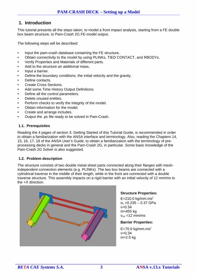
The structure consists of two double metal sheet parts connected along their flanges with mesh-independent connection elements (e.g. PLINKs). The two box beams are connected with a cylindrical traverse in the middle of their length, while in the front are connected with a double traverse structure. This assembly impacts on a rigid barrier with an initial velocity of 12 mm/ms to the +X direction.
Structure Properties:
E=210.0 kg/mm.ms2
σy =0.235 – 0.37 GPaν=0.34m≈455 kgvinit =12 mm/ms
Barrier Properties:
E=70.0 kg/mm.ms2
ν=0.34m≈2.5 kg
BETA CAE Systems S.A. 3 ANSA v.13.x Tutorials
PAM-CRASH DECK – Setting up a Model
The Properties with the proper characteristics (e.g. thickness, Material) should be assigned. The model entities have to be created, as well.Note that all the Pam-Crash entities are displayed with specific symbols and colors so as to help the visual identification and selection.For convention reasons the “Pam-Crash PART__/” entity is referred as “PART” or “Property”, while the “ANSA Part” as “Part” or “part”.
1.3. Data files
The files required for this tutorial are:• One Pam-Crash [*.pc] file containing the double box beam structure.
[tutorials/DECKS/pamcrash/tutorial_files/double_rail_initial.pc.• One *.xml file containing the connection points [connections.xml].• One Pam-Crash [*.pc] “Material database” file [material_database.pc].• One Pam-Crash [*.pc] file containing the barrier [barrier.pc].• One Header Pam-Crash [*.pc] file [header.pc].• The results can be found in the ANSA database [double_rail_final.ansa] in the same
directory for reference.
BETA CAE Systems S.A. 4 ANSA v.13.x Tutorials
PAM-CRASH DECK – Setting up a Model
2. Assembly & Welding management
2.1. Input the Pam-Crash file
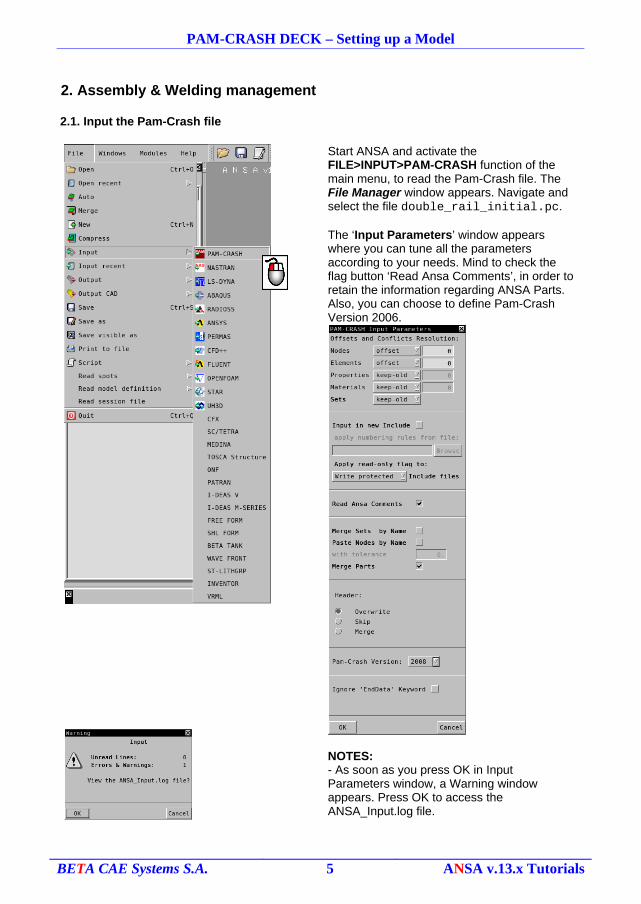
Start ANSA and activate the FILE>INPUT>PAM-CRASH function of the main menu, to read the Pam-Crash file. The File Manager window appears. Navigate and select the file double_rail_initial.pc.
The ‘Input Parameters’ window appears where you can tune all the parameters according to your needs. Mind to check the flag button ‘Read Ansa Comments’, in order to retain the information regarding ANSA Parts. Also, you can choose to define Pam-Crash Version 2006.
NOTES:- As soon as you press OK in Input Parameters window, a Warning window appears. Press OK to access the ANSA_Input.log file.
BETA CAE Systems S.A. 5 ANSA v.13.x Tutorials
PAM-CRASH DECK – Setting up a Model
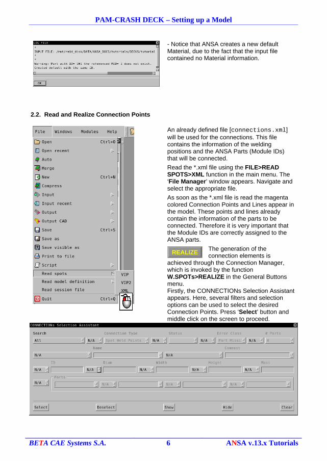
- Notice that ANSA creates a new default Material, due to the fact that the input file contained no Material information.
2.2. Read and Realize Connection Points
An already defined file [connections.xml] will be used for the connections. This file contains the information of the welding positions and the ANSA Parts (Module IDs) that will be connected.
Read the *.xml file using the FILE>READ SPOTS>XML function in the main menu. The ‘File Manager’ window appears. Navigate and select the appropriate file.
As soon as the *.xml file is read the magenta colored Connection Points and Lines appear in the model. These points and lines already contain the information of the parts to be connected. Therefore it is very important that the Module IDs are correctly assigned to the ANSA parts.
The generation of the connection elements is
achieved through the Connection Manager, which is invoked by the function W.SPOTs>REALIZE in the General Buttons menu.Firstly, the CONNECTIONs Selection Assistant appears. Here, several filters and selection options can be used to select the desired Connection Points. Press ‘Select’ button and middle click on the screen to proceed.
BETA CAE Systems S.A. 6 ANSA v.13.x Tutorials
REALIZE
PAM-CRASH DECK – Setting up a Model
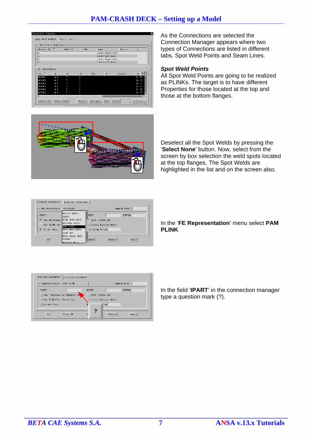
As the Connections are selected the Connection Manager appears where two types of Connections are listed in different tabs, Spot Weld Points and Seam Lines.
Spot Weld PointsAll Spot Weld Points are going to be realized as PLINKs. The target is to have different Properties for those located at the top and those at the bottom flanges.
Deselect all the Spot Welds by pressing the ‘Select None’ button. Now, select from the screen by box selection the weld spots located at the top flanges. The Spot Welds are highlighted in the list and on the screen also.
In the ‘FE Representation’ menu select PAM PLINK
In the field ‘IPART’ in the connection manager type a question mark (?).
BETA CAE Systems S.A. 7 ANSA v.13.x Tutorials
?
PAM-CRASH DECK – Setting up a Model
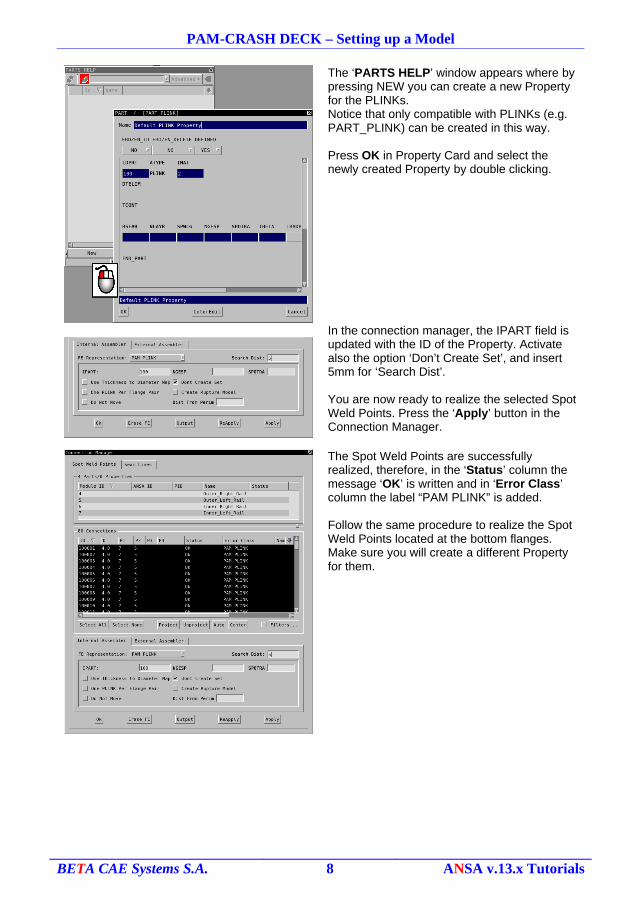
The ‘PARTS HELP’ window appears where by pressing NEW you can create a new Property for the PLINKs.Notice that only compatible with PLINKs (e.g. PART_PLINK) can be created in this way.
Press OK in Property Card and select the newly created Property by double clicking.
In the connection manager, the IPART field is updated with the ID of the Property. Activate also the option ‘Don’t Create Set’, and insert 5mm for ‘Search Dist’.
You are now ready to realize the selected Spot Weld Points. Press the ‘Apply’ button in the Connection Manager.
The Spot Weld Points are successfully realized, therefore, in the ‘Status’ column the message ‘OK’ is written and in ‘Error Class’ column the label “PAM PLINK” is added.
Follow the same procedure to realize the Spot Weld Points located at the bottom flanges. Make sure you will create a different Property for them.
BETA CAE Systems S.A. 8 ANSA v.13.x Tutorials
PAM-CRASH DECK – Setting up a Model
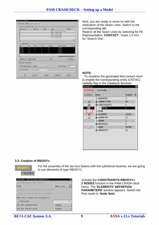
Now, you are ready to move on with the realization of the Seam Lines. Switch to the corresponding tab.Realize all the Seam Lines by selecting for FE Representation ‘CONTACT’. Insert 1.5 mm for ‘Search Dist’.
NOTE: - To visualize the generated tied contact mind to enable the corresponding entity (CNTAC) visibility flag in the Database Browser.
2.3. Creation of RBODYs
For the assembly of the two box beams with the cylindrical traverse, we are going to use elements of type RBODY1.
Activate the CONSTRAINTS>RBODY1>2 NODES function in the PAM-CRASH deck menu. The ‘ELEMENTS’ DEFINITION PARAMETERS’ window appears. Switch the Pick mode to ‘Node Sets’.
BETA CAE Systems S.A. 9 ANSA v.13.x Tutorials
2 NODES
RBODY1
PAM-CRASH DECK – Setting up a Model
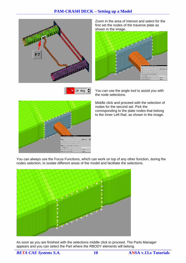
Zoom in the area of interest and select for the first set the nodes of the traverse plate as shown in the image.
You can use the angle tool to assist you with the node selections.
Middle click and proceed with the selection of nodes for the second set. Pick the corresponding to the plate nodes that belong to the Inner Left Rail, as shown in the image.
You can always use the Focus Functions, which can work on top of any other function, during the nodes selection, to isolate different areas of the model and facilitate the selections.
As soon as you are finished with the selections middle click to proceed. The Parts Manager appears and you can select the Part where the RBODY elements will belong.
BETA CAE Systems S.A. 10 ANSA v.13.x Tutorials
F7
PAM-CRASH DECK – Setting up a Model
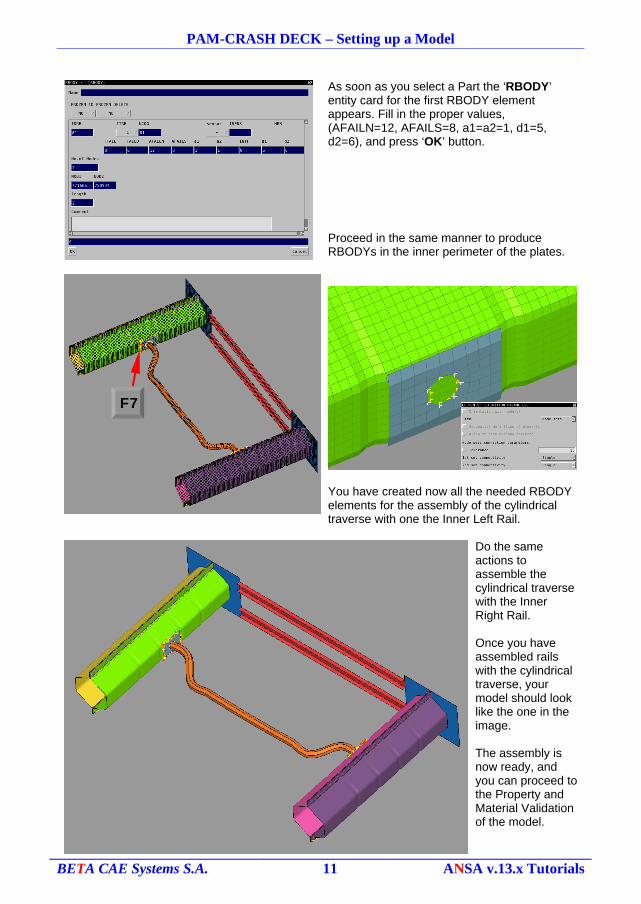
As soon as you select a Part the ‘RBODY’ entity card for the first RBODY element appears. Fill in the proper values, (AFAILN=12, AFAILS=8, a1=a2=1, d1=5, d2=6), and press ‘OK’ button.
Proceed in the same manner to produce RBODYs in the inner perimeter of the plates.
You have created now all the needed RBODY elements for the assembly of the cylindrical traverse with one the Inner Left Rail.
Do the same actions to assemble the cylindrical traverse with the Inner Right Rail.
Once you have assembled rails with the cylindrical traverse, your model should look like the one in the image.
The assembly is now ready, and you can proceed to the Property and Material Validation of the model.
BETA CAE Systems S.A. 11 ANSA v.13.x Tutorials
F7
PAM-CRASH DECK – Setting up a Model
3. Property and Material Validation
3.1. Prepare the Properties
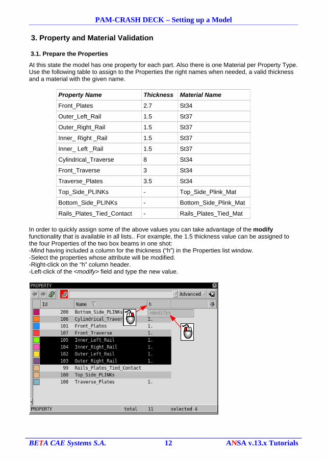
At this state the model has one property for each part. Also there is one Material per Property Type. Use the following table to assign to the Properties the right names when needed, a valid thickness and a material with the given name.
Property Name Thickness Material Name
Front_Plates 2.7 St34
Outer_Left_Rail 1.5 St37
Outer_Right_Rail 1.5 St37
Inner_ Right _Rail 1.5 St37
Inner_ Left _Rail 1.5 St37
Cylindrical_Traverse 8 St34
Front_Traverse 3 St34
Traverse_Plates 3.5 St34
Top_Side_PLINKs - Top_Side_Plink_Mat
Bottom_Side_PLINKs - Bottom_Side_Plink_Mat
Rails_Plates_Tied_Contact - Rails_Plates_Tied_Mat
In order to quickly assign some of the above values you can take advantage of the modify functionality that is available in all lists.. For example, the 1.5 thickness value can be assigned to the four Properties of the two box beams in one shot:-Mind having included a column for the thickness (“h”) in the Properties list window.-Select the properties whose attribute will be modified.-Right-click on the “h” column header.-Left-click of the <modify> field and type the new value.
BETA CAE Systems S.A. 12 ANSA v.13.x Tutorials
PAM-CRASH DECK – Setting up a Model
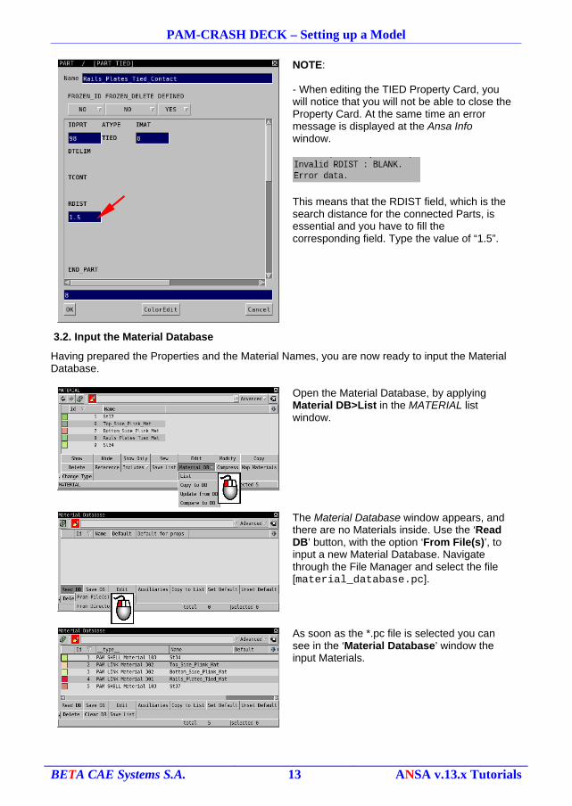
NOTE:
- When editing the TIED Property Card, you will notice that you will not be able to close the Property Card. At the same time an error message is displayed at the Ansa Info window.
This means that the RDIST field, which is the search distance for the connected Parts, is essential and you have to fill the corresponding field. Type the value of “1.5”.
3.2. Input the Material Database
Having prepared the Properties and the Material Names, you are now ready to input the Material Database.
Open the Material Database, by applying Material DB>List in the MATERIAL list window.
The Material Database window appears, and there are no Materials inside. Use the ‘Read DB’ button, with the option ‘From File(s)’, to input a new Material Database. Navigate through the File Manager and select the file [material_database.pc].
As soon as the *.pc file is selected you can see in the ‘Material Database’ window the input Materials.
BETA CAE Systems S.A. 13 ANSA v.13.x Tutorials
PAM-CRASH DECK – Setting up a Model
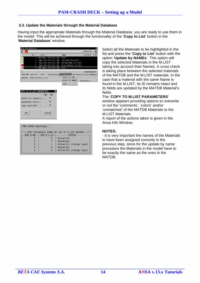
3.3. Update the Materials through the Material Database
Having input the appropriate Materials through the Material Database, you are ready to use them in the model. This will be achieved through the functionality of the ‘Copy to List’ button in the ‘Material Database’ window.
Select all the Materials to be highlighted in the list and press the ‘Copy to List’ button with the option ‘Update by NAMEs’. This option will copy the selected Materials in the M.LIST taking into account their Names. A cross check is taking place between the selected materials of the MATDB and the M.LIST materials. In the case that a material with the same Name is found in the M.LIST, its ID remains intact and its fields are updated by the MATDB Material’s fields.The ‘COPY TO M.LIST PARAMETERS’ window appears providing options to overwrite or not the ‘comments’, ‘colors’ and/or ‘unmatched’ of the MATDB Materials to the M.LIST Materials.A report of the actions taken is given in the Ansa Info Window.
NOTES:- It is very important the names of the Materials to have been assigned correctly in the previous step, since for the update by name procedure the Materials in the model have to be exactly the same as the ones in the MATDB.
BETA CAE Systems S.A. 14 ANSA v.13.x Tutorials
MASS
Set
PAM-CRASH DECK – Setting up a Model
4. Mass Definition
4.1. Additional Mass to the structure
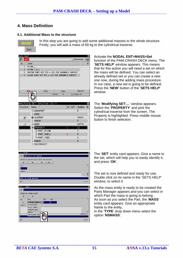
In this step you are going to add some additional masses to the whole structure.Firstly, you will add a mass of 60 kg to the cylindrical traverse.
Activate the NODAL ENT>MASS>Set function of the PAM-CRASH DECK menu. The ‘SETS HELP’ window appears. This means that for this action you will need a set on which the mass will be defined. You can select an already defined set or you can create a new one now, during the adding mass procedure. In our case, a new set is going to be defined. Press the ‘NEW’ button of the ‘SETS HELP’ window.
The ‘Modifying SET:...’ window appears. Select the ‘PROPERTY’ and pick the cylindrical traverse from the screen. The Property is highlighted. Press middle mouse button to finish selection.
The ‘SET’ entity card appears. Give a name to the set, which will help you to easily identify it, and press ‘OK’.
The set is now defined and ready for use. Double click on its name in the ‘SETS HELP’ window, to select it.
As the mass entity is ready to be created the Parts Manager appears and you can select in which Part the mass is going to belong.As soon as you select the Part, the ‘MASS’ entity card appears. Give an appropriate Name to the entity.In the ‘TYPE’ drop down menu select the option ‘NSMASS’.
BETA CAE Systems S.A. 15 ANSA v.13.x Tutorials
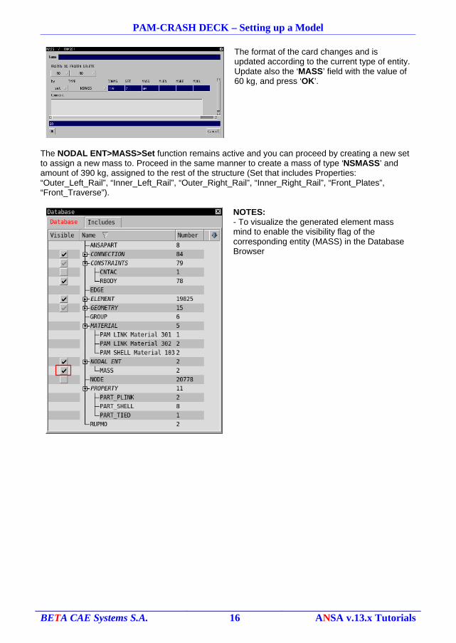
PAM-CRASH DECK – Setting up a Model
The format of the card changes and is updated according to the current type of entity.Update also the ‘MASS’ field with the value of 60 kg, and press ‘OK’.
The NODAL ENT>MASS>Set function remains active and you can proceed by creating a new set to assign a new mass to. Proceed in the same manner to create a mass of type ‘NSMASS’ and amount of 390 kg, assigned to the rest of the structure (Set that includes Properties: “Outer_Left_Rail”, “Inner_Left_Rail”, “Outer_Right_Rail”, “Inner_Right_Rail”, “Front_Plates”, “Front_Traverse”).
NOTES:- To visualize the generated element mass mind to enable the visibility flag of the corresponding entity (MASS) in the Database Browser
BETA CAE Systems S.A. 16 ANSA v.13.x Tutorials
PAM-CRASH DECK – Setting up a Model
5. Adding the Barrier
5.1. Input and position the Barrier.
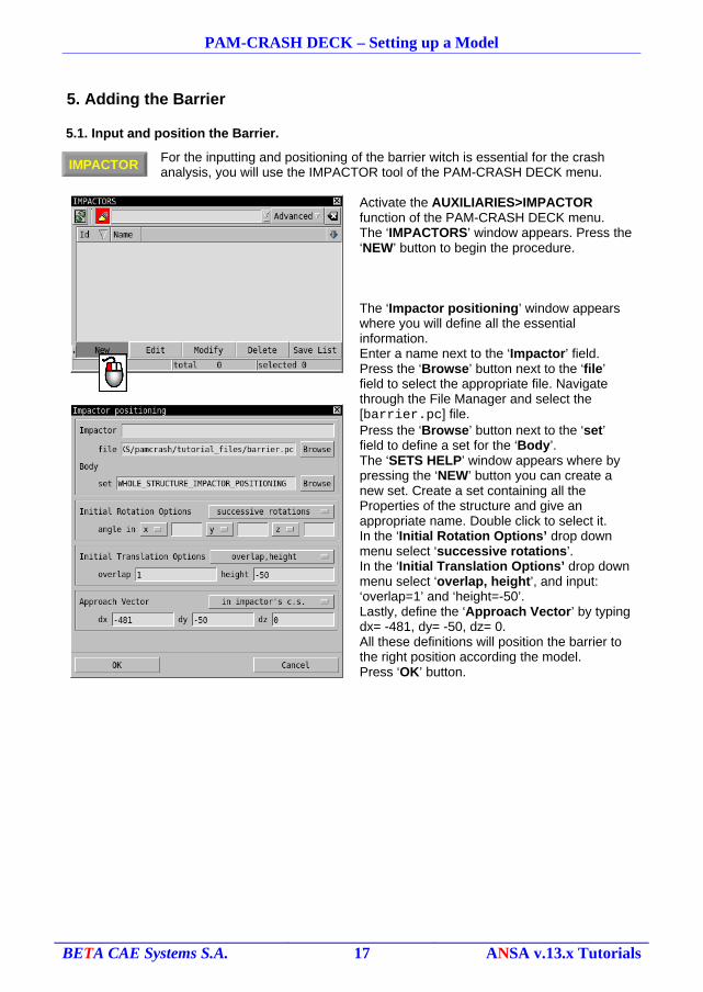
For the inputting and positioning of the barrier witch is essential for the crash analysis, you will use the IMPACTOR tool of the PAM-CRASH DECK menu.
Activate the AUXILIARIES>IMPACTOR function of the PAM-CRASH DECK menu.The ‘IMPACTORS’ window appears. Press the ‘NEW’ button to begin the procedure.
The ‘Impactor positioning’ window appears where you will define all the essential information.Enter a name next to the ‘Impactor’ field. Press the ‘Browse’ button next to the ‘file’ field to select the appropriate file. Navigate through the File Manager and select the [barrier.pc] file.Press the ‘Browse’ button next to the ‘set’ field to define a set for the ‘Body’.The ‘SETS HELP’ window appears where by pressing the ‘NEW’ button you can create a new set. Create a set containing all the Properties of the structure and give an appropriate name. Double click to select it.In the ‘Initial Rotation Options’ drop down menu select ‘successive rotations’.In the ‘Initial Translation Options’ drop down menu select ‘overlap, height’, and input: ‘overlap=1’ and ‘height=-50’.Lastly, define the ‘Approach Vector’ by typing dx= -481, dy= -50, dz= 0.All these definitions will position the barrier to the right position according the model.Press ‘OK’ button.
BETA CAE Systems S.A. 17 ANSA v.13.x Tutorials
IMPACTOR
PAM-CRASH DECK – Setting up a Model
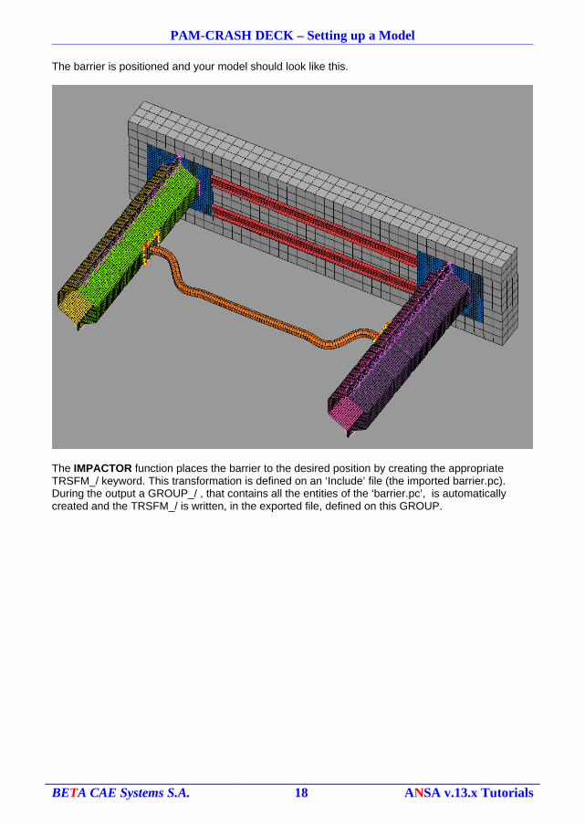
The barrier is positioned and your model should look like this.
The IMPACTOR function places the barrier to the desired position by creating the appropriate TRSFM_/ keyword. This transformation is defined on an ‘Include’ file (the imported barrier.pc). During the output a GROUP_/ , that contains all the entities of the ‘barrier.pc’, is automatically created and the TRSFM_/ is written, in the exported file, defined on this GROUP.
BETA CAE Systems S.A. 18 ANSA v.13.x Tutorials
BOUNC
Set
PAM-CRASH DECK – Setting up a Model
6. Definition of FE-model Entities
In this section you are going to define all the rest FE-model entities that are essential in this crash analysis.
6.1. Define the Boundary Conditions.
Two kinds of Boundary Conditions are needed for the analysis. One to fix the barrier at its position, and one to allow only x-directional movement for the structure.
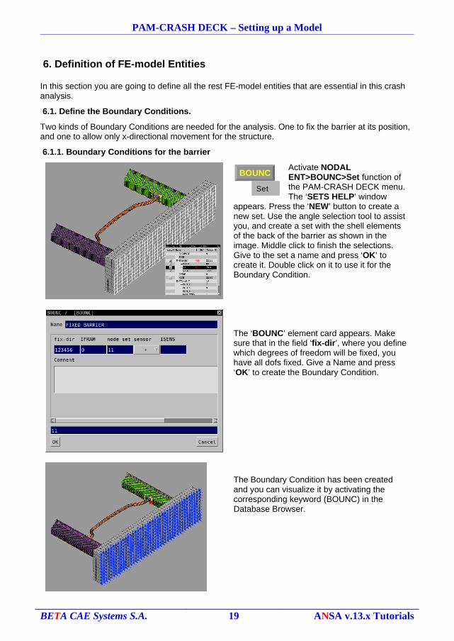
6.1.1. Boundary Conditions for the barrier
Activate NODAL ENT>BOUNC>Set function of the PAM-CRASH DECK menu.The ‘SETS HELP’ window
appears. Press the ‘NEW’ button to create a new set. Use the angle selection tool to assist you, and create a set with the shell elements of the back of the barrier as shown in the image. Middle click to finish the selections. Give to the set a name and press ‘OK’ to create it. Double click on it to use it for the Boundary Condition.
The ‘BOUNC’ element card appears. Make sure that in the field ‘fix-dir’, where you define which degrees of freedom will be fixed, you have all dofs fixed. Give a Name and press ‘OK’ to create the Boundary Condition.
The Boundary Condition has been created and you can visualize it by activating the corresponding keyword (BOUNC) in the Database Browser.
BETA CAE Systems S.A. 19 ANSA v.13.x Tutorials
INVEL
Set
PAM-CRASH DECK – Setting up a Model
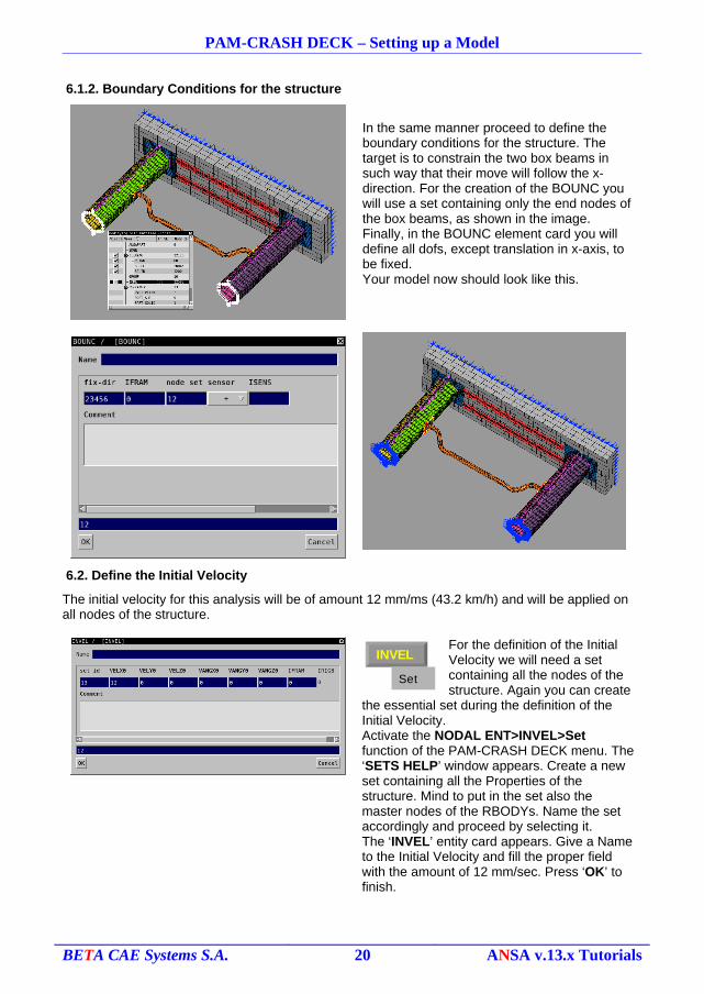
6.1.2. Boundary Conditions for the structure
In the same manner proceed to define the boundary conditions for the structure. The target is to constrain the two box beams in such way that their move will follow the x-direction. For the creation of the BOUNC you will use a set containing only the end nodes of the box beams, as shown in the image.Finally, in the BOUNC element card you will define all dofs, except translation in x-axis, to be fixed.Your model now should look like this.
6.2. Define the Initial Velocity
The initial velocity for this analysis will be of amount 12 mm/ms (43.2 km/h) and will be applied on all nodes of the structure.
For the definition of the Initial Velocity we will need a set containing all the nodes of the structure. Again you can create
the essential set during the definition of the Initial Velocity.Activate the NODAL ENT>INVEL>Set function of the PAM-CRASH DECK menu. The ‘SETS HELP’ window appears. Create a new set containing all the Properties of the structure. Mind to put in the set also the master nodes of the RBODYs. Name the set accordingly and proceed by selecting it.The ‘INVEL’ entity card appears. Give a Name to the Initial Velocity and fill the proper field with the amount of 12 mm/sec. Press ‘OK’ to finish.
BETA CAE Systems S.A. 20 ANSA v.13.x Tutorials
ACFLD
Set
PAM-CRASH DECK – Setting up a Model
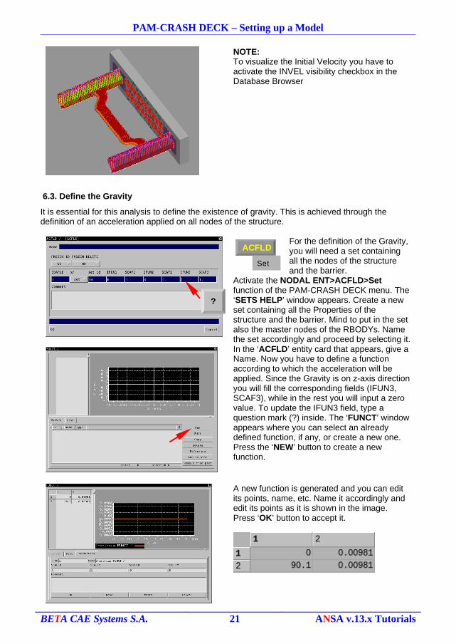
NOTE:To visualize the Initial Velocity you have to activate the INVEL visibility checkbox in the Database Browser
6.3. Define the Gravity
It is essential for this analysis to define the existence of gravity. This is achieved through the definition of an acceleration applied on all nodes of the structure.
For the definition of the Gravity, you will need a set containing all the nodes of the structure and the barrier.
Activate the NODAL ENT>ACFLD>Set function of the PAM-CRASH DECK menu. The ‘SETS HELP’ window appears. Create a new set containing all the Properties of the structure and the barrier. Mind to put in the set also the master nodes of the RBODYs. Name the set accordingly and proceed by selecting it.In the ‘ACFLD’ entity card that appears, give a Name. Now you have to define a function according to which the acceleration will be applied. Since the Gravity is on z-axis direction you will fill the corresponding fields (IFUN3, SCAF3), while in the rest you will input a zero value. To update the IFUN3 field, type a question mark (?) inside. The ‘FUNCT’ window appears where you can select an already defined function, if any, or create a new one. Press the ‘NEW’ button to create a new function.
A new function is generated and you can edit its points, name, etc. Name it accordingly and edit its points as it is shown in the image. Press ‘OK’ button to accept it.
BETA CAE Systems S.A. 21 ANSA v.13.x Tutorials
?
PAM-CRASH DECK – Setting up a Model
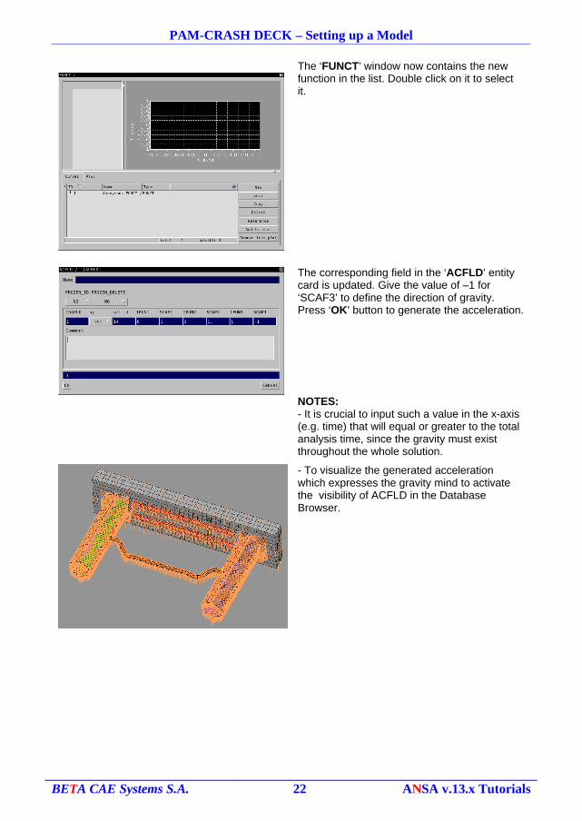
The ‘FUNCT’ window now contains the new function in the list. Double click on it to select it.
The corresponding field in the ‘ACFLD’ entity card is updated. Give the value of –1 for ‘SCAF3’ to define the direction of gravity. Press ‘OK’ button to generate the acceleration.
NOTES:- It is crucial to input such a value in the x-axis (e.g. time) that will equal or greater to the total analysis time, since the gravity must exist throughout the whole solution.
- To visualize the generated acceleration which expresses the gravity mind to activate the visibility of ACFLD in the Database Browser.
BETA CAE Systems S.A. 22 ANSA v.13.x Tutorials
PAM-CRASH DECK – Setting up a Model
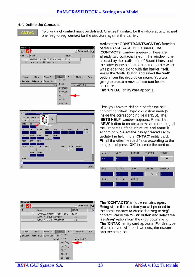
6.4. Define the Contacts
Two kinds of contact must be defined. One ‘self’ contact for the whole structure, and one ‘seg to seg’ contact for the structure against the barrier.
Activate the CONSTRAINTS>CNTAC function of the PAM-CRASH DECK menu. The ‘CONTACTS’ window appears. There are already two contacts listed in the window, one created by the realization of Seam Lines, and the other is the self contact of the barrier which was predefined along with the barrier itself.Press the ‘NEW’ button and select the ‘self’ option from the drop down menu. You are going to create a new self contact for the structure.The ‘CNTAC’ entity card appears.
First, you have to define a set for the self contact definition. Type a question mark (?) inside the corresponding field (NSS). The ‘SETS HELP’ window appears. Press the ‘NEW’ button to create a new set containing all the Properties of the structure, and name it accordingly. Select the newly created set to update the field in the ‘CNTAC’ entity card.Fill all the other needed fields according to the image, and press ‘OK’ to create the contact.
The ‘CONTACTS’ window remains open. Being still in the function you will proceed in the same manner to create the ‘seg to seg’ contact. Press the ‘NEW’ button and select the ‘seg/seg’ option from the drop down menu. The ‘CNTAC’ entity card appears. For this type of contact you will need two sets, the master and the slave set.
BETA CAE Systems S.A. 23 ANSA v.13.x Tutorials
?
CNTAC
PAM-CRASH DECK – Setting up a Model
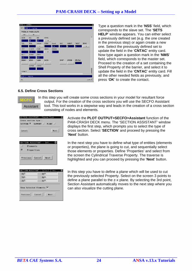
Type a question mark in the ‘NSS’ field, which corresponds to the slave set. The ‘SETS HELP’ window appears. You can either select a previously defined set (e.g. the one created in the previous step) or again create a new one. Select the previously defined set to update the field in the ‘CNTAC’ entity card. Now type again a question mark in the ‘NMS’ field, which corresponds to the master set. Proceed to the creation of a set containing the Shell Property of the barrier, and select it to update the field in the ‘CNTAC’ entity card. Fill all the other needed fields as previously, and press ‘OK’ to create the contact.
6.5. Define Cross Sections
In this step you will create some cross sections in your model for resultant force output. For the creation of the cross sections you will use the SECFO Assistant tool. This tool works in a stepwise way and leads in the creation of a cross section consisting of nodes and elements.
Activate the PLOT OUTPUT>SECFO>Assistant function of the PAM-CRASH DECK menu. The ‘SECTION ASSISTANT’ window displays the first step, which prompts you to select the type of cross section. Select ‘SECTION’ and proceed by pressing the ‘Next’ button.
In the next step you have to define what type of entities (elements or properties), the plane is going to cut, and sequentially select those elements or properties. Define ‘Properties’ and select from the screen the Cylindrical Traverse Property. The traverse is highlighted and you can proceed by pressing the ‘Next’ button.
In this step you have to define a plane which will be used to cut the previously selected Property. Select on the screen 3 points to define a plane parallel to the z-x plane. By selecting the 3rd point, Section Assistant automatically moves to the next step where you can also visualize the cutting plane.
BETA CAE Systems S.A. 24 ANSA v.13.x Tutorials
SECFO
Assistant
PAM-CRASH DECK – Setting up a Model
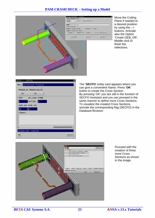
Move the Cutting Plane if needed to a desired position by using the -,+ buttons. Activate also the Option ‘Create GEB_OR’. Middle click to finish the selections.
The ‘SECFO’ entity card appears where you can give a convenient Name. Press ‘OK’ button to create the Cross Section.By pressing ‘OK’ you are still in the function of SECFO Assistant and you can proceed in the same manner to define more Cross Sections. To visualize the created Cross Sections, activate the corresponding flag (SECFO) in the Database Browser.
Proceed with the creation of three more Cross Sections as shown in the image.
BETA CAE Systems S.A. 25 ANSA v.13.x Tutorials
THxxx
PAM-CRASH DECK – Setting up a Model
NOTES:
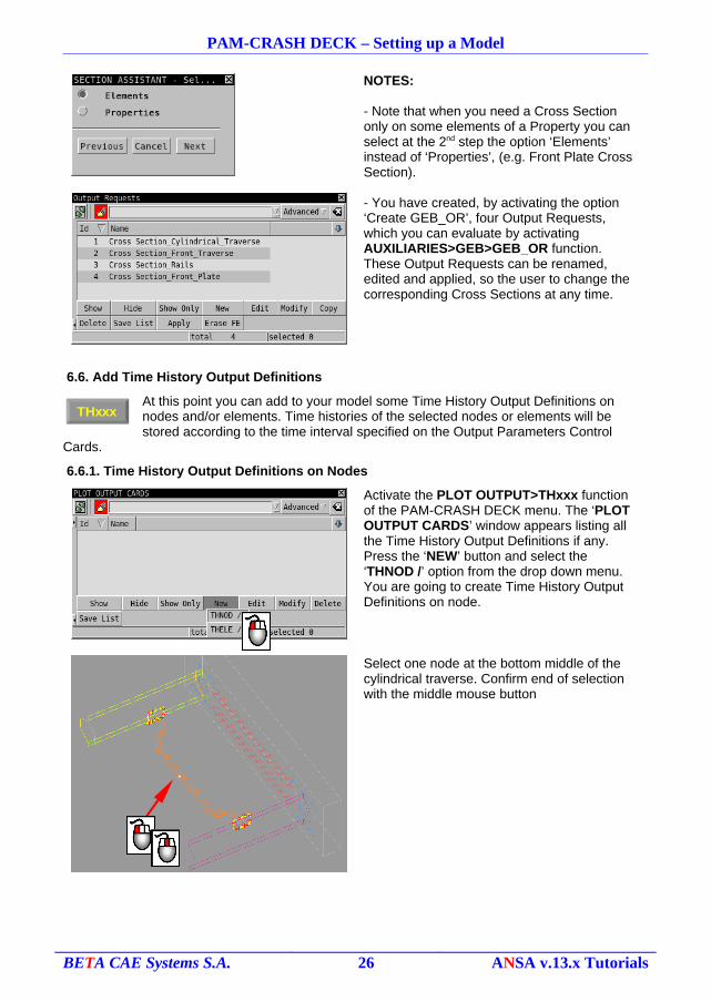
- Note that when you need a Cross Section only on some elements of a Property you can select at the 2nd step the option ‘Elements’ instead of ‘Properties’, (e.g. Front Plate Cross Section).
- You have created, by activating the option ‘Create GEB_OR’, four Output Requests, which you can evaluate by activating AUXILIARIES>GEB>GEB_OR function. These Output Requests can be renamed, edited and applied, so the user to change the corresponding Cross Sections at any time.
6.6. Add Time History Output Definitions
At this point you can add to your model some Time History Output Definitions on nodes and/or elements. Time histories of the selected nodes or elements will be stored according to the time interval specified on the Output Parameters Control
Cards.
6.6.1. Time History Output Definitions on Nodes
Activate the PLOT OUTPUT>THxxx function of the PAM-CRASH DECK menu. The ‘PLOT OUTPUT CARDS’ window appears listing all the Time History Output Definitions if any. Press the ‘NEW’ button and select the ‘THNOD /’ option from the drop down menu. You are going to create Time History Output Definitions on node.
Select one node at the bottom middle of the cylindrical traverse. Confirm end of selection with the middle mouse button
BETA CAE Systems S.A. 26 ANSA v.13.x Tutorials
PAM-CRASH DECK – Setting up a Model
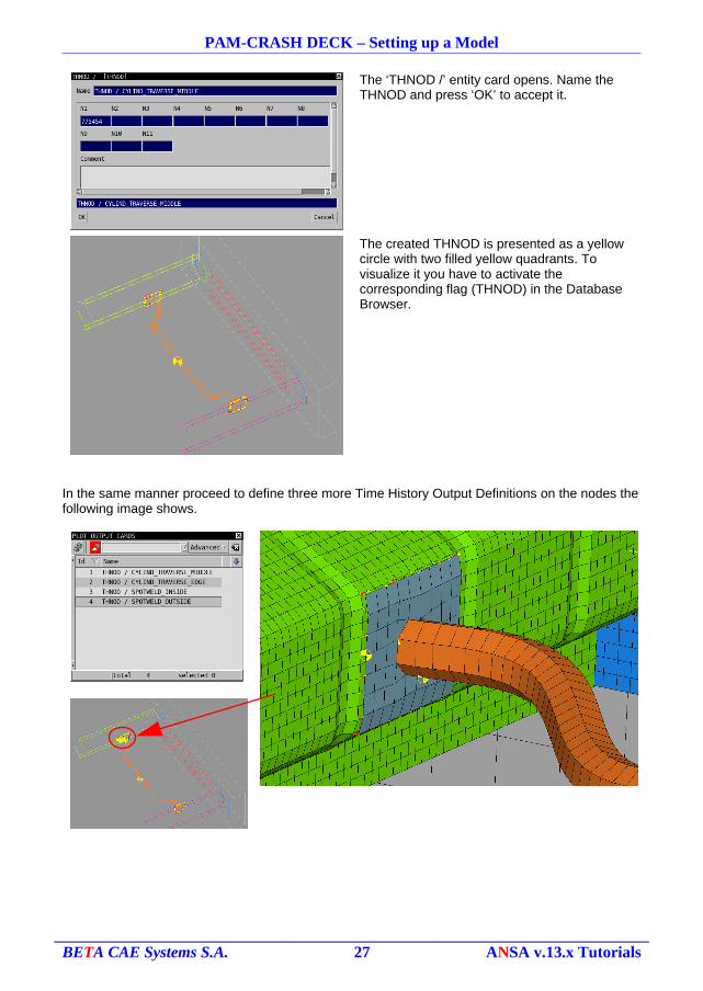
The ‘THNOD /’ entity card opens. Name the THNOD and press ‘OK’ to accept it.
The created THNOD is presented as a yellow circle with two filled yellow quadrants. To visualize it you have to activate the corresponding flag (THNOD) in the Database Browser.
In the same manner proceed to define three more Time History Output Definitions on the nodes the following image shows.
BETA CAE Systems S.A. 27 ANSA v.13.x Tutorials
PAM-CRASH DECK – Setting up a Model
6.6.2. Time History Output Definitions on Elements
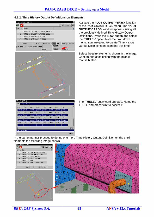
Activate the PLOT OUTPUT>THxxx function of the PAM-CRASH DECK menu. The ‘PLOT OUTPUT CARDS’ window appears listing all the previously defined Time History Output Definitions. Press the ‘New’ button and select the ‘THELE /’ option from the drop down menu. You are going to create Time History Output Definitions on elements this time.
Select the plink elements shown in the image. Confirm end of selection with the middle mouse button.
The ‘THELE /’ entity card appears. Name the THELE and press ‘OK’ to accept it.
In the same manner proceed to define one more Time History Output Definition on the shell elements the following image shows.
BETA CAE Systems S.A. 28 ANSA v.13.x Tutorials
PAM-CRASH DECK – Setting up a Model
7. Definition of Control Parameters
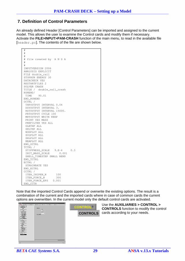
An already defined Header [Control Parameters] can be imported and assigned to the current model. This allows the user to examine the Control cards and modify them if necessary.Activate the FILE>INPUT>PAM-CRASH function of the main menu, to read in the available file [header.pc]. The contents of the file are shown below.
#### file created by A N S A ##INPUTVERSION 2006ANALYSIS EXPLICITFILE double_railSTOPRUN ENERGY 30 DATACHECK YES RESTARTFILES 2SOLVER CRASHTITLE / double_rail_crashRUNEND/ TIME 90.01END_RUNENDOCTRL / THPOUTPUT INTERVAL 0.04 DSYOUTPUT INTERVAL 3. RSTOUTPUT INTERVAL 15000. PRTOUTPUT CYCLE 100 MPPOUTPUT WRITE KEEP PRINT YES MASS PREFILTER YES ALL GLBTHP ALL SHLTHP ALL NODPLOT ALL SOLPLOT ALL SHLPLOT ALL BEAPLOT ALLEND_OCTRLTCTRL / STIFFNESS_SCALE 9.E-4 0.3 INIT_MASS_SCALE 0.001 SHELL_TIMESTEP SMALL BENDEND_TCTRLECTRL / STRAINRATE YESEND_ECTRLCCTRL / ITER_INIPEN_N 100 ITER_FORCE_N 300 ITER_FORCE_EPS 0.001END_CCTR
Note that the imported Control Cards append or overwrite the existing options. The result is a combination of the current and the imported cards where in case of common cards the current options are overwritten. In the current model only the default control cards are activated.
Use the AUXILIARIES > CONTROL > CONTROLS function to modify the control cards according to your needs.
BETA CAE Systems S.A. 29 ANSA v.13.x Tutorials
CONTROLS
CONTROL
CHECK
PAM-CRASH DECK – Setting up a Model
8. Final Steps
8.1. Clearing unused entities in your model
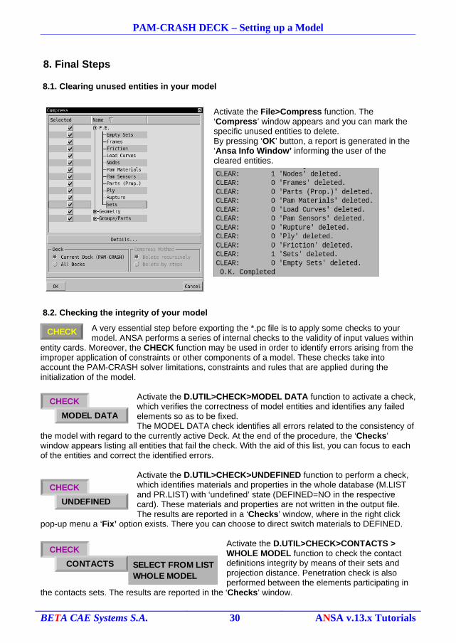
Activate the File>Compress function. The ‘Compress’ window appears and you can mark the specific unused entities to delete.By pressing ‘OK’ button, a report is generated in the ‘Ansa Info Window’ informing the user of the cleared entities.
8.2. Checking the integrity of your model
A very essential step before exporting the *.pc file is to apply some checks to your model. ANSA performs a series of internal checks to the validity of input values within
entity cards. Moreover, the CHECK function may be used in order to identify errors arising from the improper application of constraints or other components of a model. These checks take into account the PAM-CRASH solver limitations, constraints and rules that are applied during the initialization of the model.
Activate the D.UTIL>CHECK>MODEL DATA function to activate a check, which verifies the correctness of model entities and identifies any failed elements so as to be fixed.The MODEL DATA check identifies all errors related to the consistency of
the model with regard to the currently active Deck. At the end of the procedure, the ‘Checks’ window appears listing all entities that fail the check. With the aid of this list, you can focus to each of the entities and correct the identified errors.
Activate the D.UTIL>CHECK>UNDEFINED function to perform a check, which identifies materials and properties in the whole database (M.LIST and PR.LIST) with ‘undefined’ state (DEFINED=NO in the respective card). These materials and properties are not written in the output file. The results are reported in a ‘Checks’ window, where in the right click
pop-up menu a ‘Fix’ option exists. There you can choose to direct switch materials to DEFINED.
Activate the D.UTIL>CHECK>CONTACTS > WHOLE MODEL function to check the contact definitions integrity by means of their sets and projection distance. Penetration check is also performed between the elements participating in
the contacts sets. The results are reported in the ‘Checks’ window.
BETA CAE Systems S.A. 30 ANSA v.13.x Tutorials
CHECK
MODEL DATA
CHECK
UNDEFINED
SELECT FROM LIST WHOLE MODEL
CHECK
CONTACTS
PAM-CRASH DECK – Setting up a Model
Activate the D.UTIL>CHECK>DEPENDENCY PAM-CRASH function to perform a check that identifies errors related to Rigid Body definitions. The check affects visible entities and the results are reported in the ‘Checks’ window. There is an
automatic ‘Fix’ procedure that corrects DEPENDENCY conflicts.
Activate the D.UTIL>CHECK>PLINKS function of the PAM-CRASH DECK menu to activate a check that identifies errors related to the integrity of visible PLINK elements. It takes into account the search radius (RSEAR of the PART_PLINK), the components of the PLINK sets and the
number of layers. Results are reported in the Checks window.
8.3. Organizing your model in Includes
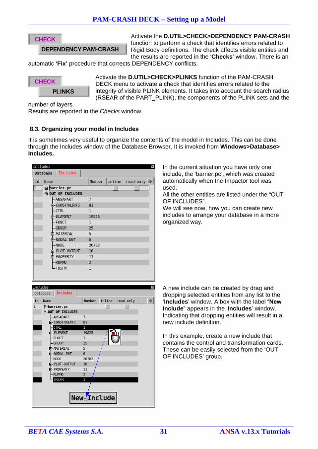
It is sometimes very useful to organize the contents of the model in Includes. This can be done through the Includes window of the Database Browser. It is invoked from Windows>Database> Includes.
In the current situation you have only one include, the ‘barrier.pc’, which was created automatically when the Impactor tool was used.All the other entities are listed under the “OUT OF INCLUDES”.We will see now, how you can create new includes to arrange your database in a more organized way.
A new include can be created by drag and dropping selected entities from any list to the ‘Includes’ window. A box with the label “New Include” appears in the ‘Includes’ window. Indicating that dropping entities will result in a new include definition.
In this example, create a new include that contains the control and transformation cards. These can be easily selected from the ‘OUT OF INCLUDES’ group.
BETA CAE Systems S.A. 31 ANSA v.13.x Tutorials
CHECK
DEPENDENCY PAM-CRASH
CHECK
PLINKS
PAM-CRASH DECK – Setting up a Model
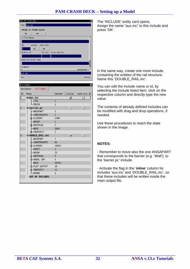
The ‘INCLUDE’ entity card opens.Assign the name “aux.inc” to this include and press ‘OK’.
In the same way, create one more include, containing the entities of the rail structure. Name this ‘DOUBLE_RAIL.inc’.
You can edit the include name or id, by selecting the include listed item, click on the respective column and directly type the new value.
The contents of already defined Includes can be modified with drag and drop operations, if needed.
Use these procedures to reach the state shown in the image.
NOTES:
- Remember to move also the one ANSAPART that corresponds to the barrier (e.g. ‘Wall’), to the ‘barrier.pc’ include.
- Activate the flag in the ‘inline’ column for includes ‘aux.inc’ and ‘DOUBLE_RAIL.inc’, so that these includes will be written inside the main output file.
BETA CAE Systems S.A. 32 ANSA v.13.x Tutorials
PAM-CRASH DECK – Setting up a Model
8.4. Deck Information report
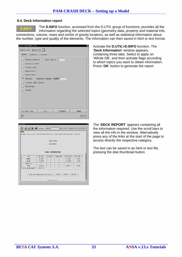
The D.INFO function, accessed from the D.UTIL group of functions, provides all the information regarding the selected topics (geometry data, property and material info,
connections, volume, mass and centre of gravity location), as well as statistical information about the number, type and quality of the elements. The information can then saved in html or text format.
Activate the D.UTIL>D.INFO function. The ‘Deck Information’ window appears, containing three tabs. Select to apply on ‘Whole DB’, and then activate flags according to which topics you want to obtain information. Press ‘OK’ button to generate the report.
The ‘DECK REPORT’ appears containing all the information required. Use the scroll bars to view all the info in the window. Alternatively press any of the links at the start of the page to access directly the respective category.
The text can be saved in an html or text file, pressing the disk thumbnail button.
BETA CAE Systems S.A. 33 ANSA v.13.x Tutorials
D.INFO
PAM-CRASH DECK – Setting up a Model
9. Output the file
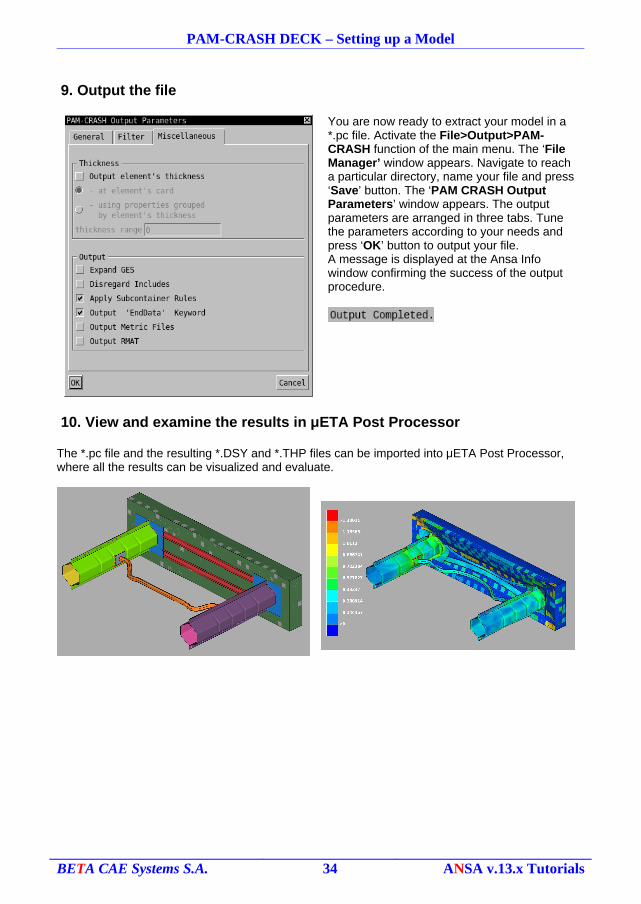
You are now ready to extract your model in a *.pc file. Activate the File>Output>PAM-CRASH function of the main menu. The ‘File Manager’ window appears. Navigate to reach a particular directory, name your file and press ‘Save’ button. The ‘PAM CRASH Output Parameters’ window appears. The output parameters are arranged in three tabs. Tune the parameters according to your needs and press ‘OK’ button to output your file.A message is displayed at the Ansa Info window confirming the success of the output procedure.
10. View and examine the results in μETA Post Processor
The *.pc file and the resulting *.DSY and *.THP files can be imported into μETA Post Processor, where all the results can be visualized and evaluate.
BETA CAE Systems S.A. 34 ANSA v.13.x Tutorials