Embed Size (px)
Citation preview

SAND REPORTSAND2008-1933Unlimited ReleasePrinted April 2008
Pamgen, a Library for ParallelGeneration of Simple Finite ElementMeshes
David M. Hensinger, Richard R. Drake, James G. Foucar, Thomas A. Gardiner
Prepared bySandia National LaboratoriesAlbuquerque, New Mexico 87185 and Livermore, California 94550
Sandia is a multiprogram laboratory operated by Sandia Corporation,a Lockheed Martin Company, for the United States Department of Energy’sNational Nuclear Security Administration under Contract DE-AC04-94-AL85000.
Approved for public release; further dissemination unlimited.

Issued by Sandia National Laboratories, operated for the United States Department ofEnergy by Sandia Corporation.
NOTICE: This report was prepared as an account of work sponsored by an agency ofthe United States Government. Neither the United States Government, nor any agencythereof, nor any of their employees, nor any of their contractors, subcontractors, or theiremployees, make any warranty, express or implied, or assume any legal liability or re-sponsibility for the accuracy, completeness, or usefulness of any information, appara-tus, product, or process disclosed, or represent that its use would not infringe privatelyowned rights. Reference herein to any specific commercial product, process, or serviceby trade name, trademark, manufacturer, or otherwise, does not necessarily constituteor imply its endorsement, recommendation, or favoring by the United States Govern-ment, any agency thereof, or any of their contractors or subcontractors. The views andopinions expressed herein do not necessarily state or reflect those of the United StatesGovernment, any agency thereof, or any of their contractors.
Printed in the United States of America. This report has been reproduced directly fromthe best available copy.
Available to DOE and DOE contractors fromU.S. Department of EnergyOffice of Scientific and Technical InformationP.O. Box 62Oak Ridge, TN 37831
Telephone: (865) 576-8401Facsimile: (865) 576-5728E-Mail: [email protected] ordering: http://www.doe.gov/bridge
Available to the public fromU.S. Department of CommerceNational Technical Information Service5285 Port Royal RdSpringfield, VA 22161
Telephone: (800) 553-6847Facsimile: (703) 605-6900E-Mail: [email protected] ordering: http://www.ntis.gov/help/ordermethods.asp?loc=7-4-0#online
DEP
ARTMENT OF ENERGY
• • UN
ITED
STATES OF AM
ERIC
A
SAND2008-1933Unlimited ReleasePrinted April 2008
Pamgen, a Library for ParallelGeneration of Simple Finite Element
Meshes
D. M. Hensinger, R. R. Drake, J. G. Foucar, T. A. GardinerSandia National Laboratories
P.O. Box 5800Albuquerque, NM 87185-0378
Abstract
Generating finite-element meshes is a serious bottleneck for largeparallel simulations. When mesh generation is limited to serial ma-chines and element counts approach a billion, this bottleneck becomesa roadblock. pamgen is a parallel mesh generation library that allowson-the-fly scalable generation of hexahedral and quadrilateral finiteelement meshes for several simple geometries. It has been used togenerate more that 1.1 billion elements on 17,576 processors.
pamgen generates an unstructured finite element mesh on eachprocessor at the start of a simulation. The mesh is specified by com-mands passed to the library as a ”C”-programming language string.The resulting mesh geometry, topology, and communication informa-tion can then be queried through an API. pamgen allows specifica-tion of boundary condition application regions using sidesets (elementfaces) and nodesets (collections of nodes). It supports several sim-ple geometry types. It has multiple alternatives for mesh grading. Ithas several alternatives for the initial domain decompositon. pamgenmakes it easy to change details of the finite element mesh and is veryusesful for performance studies and scoping calculations.
3

Acknowledgment
The pamgen capabilities would not have been developed without the supportand inspiration of the alegra community of users and developers. Withinthe users community, Chris Garasi and his challenging analysis requirementswere the spur for development of the most complex and rewarding capa-bilities. Tom Brunner severely stressed the code with his early testing onlarge platforms. Within the developers community, the build and bench-mark utilities written by Richard Drake enabled continual improvement infunctionality and robustness. Tom Gardiner provided the code that is theheart of the default load balance capability.
4

Contents
1 Introduction 11
2 Capabilities 12
2.1 Dimensions . . . . . . . . . . . . . . . . . . . . . . . . . . . . 12
2.2 Mesh Geometries . . . . . . . . . . . . . . . . . . . . . . . . . 12
2.3 Boundary Conditions . . . . . . . . . . . . . . . . . . . . . . . 13
2.4 Decomposition . . . . . . . . . . . . . . . . . . . . . . . . . . 13
2.5 Geometry Transformation . . . . . . . . . . . . . . . . . . . . 13
2.6 Element Density . . . . . . . . . . . . . . . . . . . . . . . . . 14
3 Approach 15
4 Usage 16
5 Specifying a Mesh 17
5.1 Dimensionality . . . . . . . . . . . . . . . . . . . . . . . . . . 17
5.2 Block IDs . . . . . . . . . . . . . . . . . . . . . . . . . . . . . 18
5.3 Geometry and Topology . . . . . . . . . . . . . . . . . . . . . 19
5.3.1 Rectilinear . . . . . . . . . . . . . . . . . . . . . . . . . 19
5.3.2 Spherical . . . . . . . . . . . . . . . . . . . . . . . . . . 21
5.3.3 Cylindrical . . . . . . . . . . . . . . . . . . . . . . . . . 23
5.3.4 Radial and Radial Trisection . . . . . . . . . . . . . . . 25
5.3.5 Brick . . . . . . . . . . . . . . . . . . . . . . . . . . . . 32
5.4 Boundary Conditions (Nodesets and Sidesets) . . . . . . . . . 34
5

5.5 User Defined Geometry Transformation . . . . . . . . . . . . . 37
5.6 User Defined Element Density . . . . . . . . . . . . . . . . . . 40
5.7 Decomposition Strategy . . . . . . . . . . . . . . . . . . . . . 42
6 Library Interface 46
6.1 Creating a Mesh . . . . . . . . . . . . . . . . . . . . . . . . . 46
6.1.1 Create Pamgen Mesh . . . . . . . . . . . . . . . . . . . 46
6.1.2 getPamgenEchoStreamSize . . . . . . . . . . . . . . . . 47
6.1.3 getPamgenEchoStream . . . . . . . . . . . . . . . . . . 47
6.1.4 getPamgenErrorStreamSize . . . . . . . . . . . . . . . 47
6.1.5 getPamgenErrorStream . . . . . . . . . . . . . . . . . . 47
6.1.6 getPamgenWarningStreamSize . . . . . . . . . . . . . . 48
6.1.7 getPamgenWarningStream . . . . . . . . . . . . . . . . 48
6.1.8 getPamgenInfoStreamSize . . . . . . . . . . . . . . . . 48
6.1.9 getPamgenInfoStream . . . . . . . . . . . . . . . . . . 48
6.2 Querying a Mesh . . . . . . . . . . . . . . . . . . . . . . . . . 50
6.2.1 im ex get init . . . . . . . . . . . . . . . . . . . . . . . 50
6.2.2 im ex inquire . . . . . . . . . . . . . . . . . . . . . . . 51
6.2.3 im ex get coord . . . . . . . . . . . . . . . . . . . . . . 52
6.2.4 im ex get coord names . . . . . . . . . . . . . . . . . . 52
6.2.5 im ex get map . . . . . . . . . . . . . . . . . . . . . . . 53
6.2.6 im ex get elem num map . . . . . . . . . . . . . . . . . 53
6.2.7 im ex get node num map . . . . . . . . . . . . . . . . . 54
6.2.8 im ex get elem blk ids . . . . . . . . . . . . . . . . . . 54
6

6.2.9 im ex get elem block . . . . . . . . . . . . . . . . . . . 54
6.2.10 im ex get elem conn . . . . . . . . . . . . . . . . . . . 55
6.2.11 im ex get node set ids . . . . . . . . . . . . . . . . . . 56
6.2.12 im ex get node set param . . . . . . . . . . . . . . . . 57
6.2.13 im ex get node set . . . . . . . . . . . . . . . . . . . . 57
6.2.14 im ex get side set ids . . . . . . . . . . . . . . . . . . . 58
6.2.15 im ex get side set param . . . . . . . . . . . . . . . . . 58
6.2.16 im ex get side set . . . . . . . . . . . . . . . . . . . . . 59
6.2.17 im ex get qa . . . . . . . . . . . . . . . . . . . . . . . . 59
6.2.18 im ex get info . . . . . . . . . . . . . . . . . . . . . . . 60
6.2.19 im ne get init global . . . . . . . . . . . . . . . . . . . 61
6.2.20 im ne get init info . . . . . . . . . . . . . . . . . . . . 62
6.2.21 im ne get eb info global . . . . . . . . . . . . . . . . . 62
6.2.22 im ne get ns param global . . . . . . . . . . . . . . . . 63
6.2.23 im ne get ss param global . . . . . . . . . . . . . . . . 63
6.2.24 im ne get loadbal param . . . . . . . . . . . . . . . . . 64
6.2.25 im ne get elem map . . . . . . . . . . . . . . . . . . . 65
6.2.26 im ne get node map . . . . . . . . . . . . . . . . . . . 66
6.2.27 im ne get cmap params . . . . . . . . . . . . . . . . . 66
6.2.28 im ne get node cmap . . . . . . . . . . . . . . . . . . . 67
6.2.29 im ne get elem cmap . . . . . . . . . . . . . . . . . . . 68
6.3 Deleting a Mesh . . . . . . . . . . . . . . . . . . . . . . . . . . 69
6.3.1 Delete Pamgen Mesh . . . . . . . . . . . . . . . . . . . 69
7

A Runtime Compiler Functionality 70
A.1 The RTC language . . . . . . . . . . . . . . . . . . . . . . . . 70
A.1.1 Operators . . . . . . . . . . . . . . . . . . . . . . . . . 70
A.1.2 Control flow . . . . . . . . . . . . . . . . . . . . . . . . 71
A.1.3 Line Structure . . . . . . . . . . . . . . . . . . . . . . . 72
A.1.4 Variables . . . . . . . . . . . . . . . . . . . . . . . . . . 72
A.1.5 Math . . . . . . . . . . . . . . . . . . . . . . . . . . . . 73
A.1.6 Strings . . . . . . . . . . . . . . . . . . . . . . . . . . . 74
A.1.7 Printf . . . . . . . . . . . . . . . . . . . . . . . . . . . 74
A.1.8 Comments . . . . . . . . . . . . . . . . . . . . . . . . . 75
A.1.9 Unsupported Features . . . . . . . . . . . . . . . . . . 75
B read mesh to memory 76
References 84
Index 86
8
List of Figures
1 The mesh geometry zoo in 3D. . . . . . . . . . . . . . . . . . . 12
2 Examples of geometry transformation. . . . . . . . . . . . . . 13
3 Definition of a three-dimensional RECTILINEAR mesh. . . . . . 20
4 Definition of a two-dimensional spherical mesh. . . . . . . . . 22
5 Definition of a three-dimensional spherical mesh. . . . . . . . . 22
6 Three dimensional CYLINDRICAL mesh. . . . . . . . . . . . . . 24
7 Three dimensional RADIAL mesh. . . . . . . . . . . . . . . . . 27
8 A 360 degree RADIAL mesh. . . . . . . . . . . . . . . . . . . . 28
9 A RADIAL TRISECTION mesh with three trisection blocks. . . . 29
10 A RADIAL TRISECTION mesh with three trisection blocks. . . . 30
11 A 360 degree RADIAL TRISECTION mesh. . . . . . . . . . . . . 31
12 Three dimensional BRICK mesh. . . . . . . . . . . . . . . . . . 33
13 Block topology and labels. . . . . . . . . . . . . . . . . . . . . 35
14 A RADIAL TRISECTION mesh with sidesets. . . . . . . . . . . . 36
15 3D Geometry Transformation Example . . . . . . . . . . . . . 38
16 2D Geometry Transformation Example . . . . . . . . . . . . . 39
17 2D mesh created with a USER DEFINED ELEMENT DENSITY. . . 41
18 BISECTION decomposition run on 7 processors. . . . . . . . . . 43
19 PROCESSOR LAYOUT decomposition run on 8 processors. . . . . 44
20 PROCESSOR LAYOUT decomposition on 8 processors. . . . . . . 44
9

List of Tables
1 Keywords for RECTILINEAR -- END. . . . . . . . . . . . . . . 19
2 Keywords for SPHERICAL -- END. . . . . . . . . . . . . . . . 21
3 Keywords for CYLINDRICAL -- END. . . . . . . . . . . . . . . 23
4 Keywords for DECOMPOSITION STRATEGY -- END. . . . . . . . 45
10

1 Introduction
To overcome the challenge of producing multi-million finite element meshesfor simulations using more than 1000 processors a library has been developed(pamgen) that for several simple geometries produces each processor’s meshas an early step of the analysis execution. The specification for these meshesis provided by a block of terse instructions that may be placed in an input file.These instructions are passed to the library as a ”C”-programming languagecharacter array. pamgen is also referred to as an “in line” mesh generatorbecause the meshing instructions may be included in one of the analysis inputdecks.
The simple input format allows analysts to change the resolution of asimulation by altering a few parameters. It also allows them to executetheir simulations on different numbers of processors without requiring anypre-processing.
The mesh generation proceeds through steps of decomposition, local ele-ment creation, and communication information generation. The final productof the library is a data structure that can be queried using an API (Applica-tion Programming Interface) that is based on the NEMESIS and EXODUSAPIs. Currently the library is limited to generating meshes of domains withcylindrical, tubular, and block shapes. Substantial control is allowed over theelement density within these shapes. Boundary condition application regionscan be specified on the surfaces and interior of the mesh .
Development of this capability revealed that the parallel mesh generationprocess can be reduced to answering a series of questions: What elements areon this processor? What nodes are on this processor? What is the connec-tivity of this element? What elements border this element? What processordoes this element reside on?... Resolving these questions inductively, withoutresolution to communication, is essential for preserving scalability. Once aframework for posing and answering these questions for a particular geome-try is established, expanding the capability to support additional geometriesis straightforward.
11

2 Capabilities
The capabilities of pamgen are best understood by studying Section 5,which documents in detail the instructions available for specifying a mesh.This section provides a brief overview of the library’s capabilities. pamgenwill be distributed as part of the Trilinos package of matrix and finiteelement tools.
2.1 Dimensions
pamgen can create both two and three dimensional meshes. It createsquadrilateral finite element meshes if two dimensions are specified, and itcreates hexahedral finite element meshes if three dimensions are specified.For two dimensional quadrilateral meshes the Z component of nodal coordi-nates is not supplied.
2.2 Mesh Geometries
The pamgen library handles the mesh geometries shown below:
• Bricks
• Partial hollow cylinders
• Complete hollow cylinders
• Partial solid cylinders
• Complete solid cylinders
Figure 1: The mesh geometry zoo in 3D.
12

2.3 Boundary Conditions
Boundary conditions application regions in the form of node sets and sidesets can be applied to the face, edge, or corner of any element block in thefinite element mesh. They may also be applied to any face, edge, or cornerof the entire mesh.
2.4 Decomposition
There are several mesh decomposition strategies available in pamgen:
• A default decomposition based on a constrained optimized solution thatslices through the entire mesh in its three (or two in 2D) topologicaldimensions.
• A user defined slicing strategy that specifies the number of slicesthrough the mesh in each topological direction.
• A sequential strategy that distributes elements beetween processorsbased on their element ids with the first n elements going to processor0 ...
• A random strategy that assigns element to processors randomly.
2.5 Geometry Transformation
Any mesh can be modified by re-evaluating the nodal coordinate values usinga user-supplied function. This function has the original nodal coordinates asinput values. Its output values define the new nodal coordinates.
Figure 2: Examples of geometry transformation.
13

2.6 Element Density
Several of the geometry types allow specification of first and last elementsizes within a block in a particular cartesian direction. In addition the usermay control node distribution over any geometry by providing a user defineddistribution function. This function is evaluated so that nodes are shiftedtowards areas where the function has its highest values.
14

3 Approach
pamgen operates on the premise that mesh generation is deterministic. Thismeans that every execution of code compiled with compiler A and run onprocessor B under operating system C reading mesh instructions file D willproduce an identical mesh. The mesh will have the same topology and thenodes will have the same coordinate locations. On a multi-processor machineof identical nodes an arbitrary number of processors executing identical in-structions produce an identical mesh. Use of pamgen on heterogeneousmachines may produce unexpected results.
With one significant exception, pamgen operates in the same way asthese identical processors producing identical mesh. The exception is thateach processor only allocates for a subset of the nodes and elements, andeach processor performs topology and geometry calculations only for theentities and dependencies present on that processor. pamgen exploits thefact that each processor is capable of producing the entire mesh in order toallow each processor to produce its own mesh. The deterministic nature ofthe meshing process is essential to allow correspondence in topologies andgeometries produced on adjacent processors.
The implementation of the mesh generation in pamgen is as much aspossible implicit. Quantities are not allocated until they are ready for out-put, and they are not calculated until they can be stored, or until they arerequired by a dependent calculation. This approach can result in duplica-tion of intermediate calculations, but it avoids the severe limitations on totalproblem size that occur if attempts are made to allocate any quantity witha size related to the total mesh size.
15

4 Usage
For the few simple geometries and element types it supports, the pamgenlibrary is a substitute for pre-processed finite element mesh files. Successfulusage of the library requires some modification of the analysis code.
The pamgen library must be linked into the analysis executable to allowaccess to the mesh creation, query and deletion functions.
The modules in the analysis code that read finite element mesh data froma file must be adapted to:
• Read in a “C”-progamming language string that specifices the geome-try, topology, and boundary conditions of a mesh.
• Pass that string to the pamgen Create Pamgen Mesh(...) functionalong with the rank of the mesh requested and the total number ofprocessors across which the mesh is spread.
• Handle message and possibly error strings available after calling Cre-ate Pamgen Mesh(...).
• Call the pamgen query functions to populate the analysis code’s meshand communication data structures.
• Call the pamgen Delete Pamgen Mesh() function release memory al-located within the library.
The source code for a stand-alone executable called “pamgen lt c” is dis-tributed with the pamgen library. This example code is an excellent startingpoint for adapting an analysis code to use the pamgen library.
16

5 Specifying a Mesh
The “C”-programming language string passed to pamgen is the completedefinition of the mesh’s geometry, topology, node sets, side sets, and par-allel decomposition. It must begin with a MESH keyword, and it must endwith an END keyword. The MESH -- END keyword pair must surround aRECTILINEAR -- END, SPHERICAL -- END, BRICK -- END, RADIAL -- END,RADIAL TRISECTION -- END, or CYLINDRICAL -- END keyword pair andmay have additional SET ASSIGN -- END, DECOMPOSITION STRATEGY --
END, USER DEFINED ELEMENT DENSITY -- END, or USER DEFINED GEOMETRY
TRANSFORMATION -- END keyword pairs.
MESH
{RECTILINEAR | SPHERICAL | BRICK | RADIAL | RADIAL TRISECTION | CYLINDRICAL}
[subkeyword-list]
END
[SET ASSIGN]
[END]
[DECOMPOSITION STRATEGY]
[END]
[USER DEFINED GEOMETRY TRANSFORMATION]
[END]
[USER DEFINED ELEMENT DENSITY]
[END]
END
5.1 Dimensionality
The dimensionality of the mesh is not specified in the “C” programming lan-guage string. It is passed to the pamgen library at execution time throughthe pamgen API. In general a 2D mesh can be specified by removing 3D spe-cific keywords and values (those referencing a third coordinate [for exampleZ or k]) from a 3D mesh description.
17

5.2 Block IDs
The finite elements created using pamgen are grouped into blocks. Eachblock has a positive non-zero id. These ids are automatically assigned bypamgen and are not under the control of the user. If there is a single blockthen its id is 1. When there are more than one block, the ids are assignedbeginning with the block in the lowest topological position in i, j, k space.Subsequent blocks are incrementally numbered first in the i topological di-rection, next in the j topological direction, and finally in the k topologicaldirection. In the case of BRICK and RECTILINEAR meshes i, j, and k corre-spond to the coordinate directions x, y, and z. In the case of CYLINDRICAL,RADIAL, and RADIAL TRISECTION meshes i, j, and k correspond to r, θ, andz.
18

5.3 Geometry and Topology
5.3.1 Rectilinear
RECTILINEAR
[subkeyword-list]
END
The RECTILINEAR -- END block pair surrounds the description of thegeometry of a rectilinear mesh. The extent of the domain is given by apair of vectors (gmin and gmax). The number of blocks in each coordinatedirection and the number of elements in each block are given by additionalkeywords. The total number of elements specified in this type of mesh is theproduct of the total number of blocks BX × BY × BZ and the total numberof elements per block NX × NY × NZ. For a 2D mesh NZ and BZ must beomitted. The keywords associated with the RECTILINEAR keyword are givenin Table 1.
Table 1: Keywords for RECTILINEAR -- END.
Sub-Keyword Input Description
NX int Number of cells in x-direction.NY int Number of cells in y-direction.NZ int Number of cells in z-direction.BX int Number of blocks in the x-direction.BY int Number of blocks in the y-direction.BZ int Number of blocks in the z-direction.GMIN vector Minimum domain coordinates (x,y,z).GMAX vector Maximum domain coordinates (x,y,z).
An example of a mesh specification with the RECTILINEAR option is illus-trated in Figure 3.
19

mesh
rectilinear
nx = 10
ny = 10
nz = 10
bx = 4
by = 7
bz = 5
gmin = 1.0 1.0 1.0
gmax = 4.0 7.0 5.0
end
set assign
nodeset,ihi,2
nodeset,jhi,1
end
end
Figure 3: Definition of a three-dimensional RECTILINEAR mesh.
20

5.3.2 Spherical
SPHERICAL
[subkeyword-list]
END
The SPHERICAL -- END block pair allows the description of a curvilin-ear spherical mesh centered at the origin and described by an inner andouter radius, and the extent of revolution in θ and φ directions. Angle θ ismeasured counter-clockwise about the z-axis from the x-axis, and angle φ ismeasured counter-clockwise from the y-axis about the x-axis. The numberof elements and blocks in each curvilinear coordinate direction are specifiedby the keywords in Table 2. The parameters PHI, NPHI, and BPHI are onlyappropriate for 3D problems. When used in 2D simulations, CYLINDRICALand SPHERICAL keywords produce identical meshes.
Table 2: Keywords for SPHERICAL -- END.
Sub-Keyword Input Description
NR int Number of cells in r-direction.NTHETA int Number of cells in θ-direction.NPHI int Number of cells in φ-direction.BR int Number of blocks in the r-direction.BTHETA int Number of blocks in θ-direction.BPHI int Number of blocks in φ-direction.RI real Inner radiusRO real Outer radiusTHETA real Angular extent in θ (degrees,0.-180. in 3D, 0.-360.
in 2D)PHI real Angular extent in φ (0.-360)
An example of a mesh definition syntax with the SPHERICAL option isillustrated in Figure 4 for a 2D simulation. An example of 3D spherical meshgeneration follows in Figure 5.
21

mesh
spherical
ri = 0.0
ro = 0.5
theta = 45
ntheta = 10
nr = 20
br = 2
btheta = 2
end
end
Figure 4: Definition of a two-dimensional spherical mesh.
mesh
spherical
ri = 0.5
ro = 1.0
theta = 180.0
ntheta = 10
nr = 10
br = 2
btheta = 2
bphi = 2
nphi = 10
phi = 90
end
end
Figure 5: Definition of a three-dimensional spherical mesh.
22

5.3.3 Cylindrical
CYLINDRICAL
[subkeyword-list]
END
The CYLINDRICAL -- END block pair allows the description of a curvilin-ear cylindrical mesh centered at the origin in x and y, and aligned along thez-axis. It is described by an inner and outer radius, the extent of revolutionin angle θ about the z-axis, and its start and end in the z-direction. Angle θis measured counter-clockwise about the z-axis from the x-axis. The numberof elements and blocks in each indicial direction are specified by the keywordsin Table 3. The parameters ZMIN, ZMAX, NZ, and BZ are only appropriatefor 3D problems. When used in 2D solutions, CYLINDRICAL and SPHERICAL
produce identical meshes.
Table 3: Keywords for CYLINDRICAL -- END.
Sub-Keyword Input Description
NR int Number of cells in r-direction.NTHETA int Number of cells in θ-direction.NZ int Number of cells in z-direction.BR int Number of blocks in the r-direction.BTHETA int Number of blocks in θ-direction.BZ int Number of blocks in z-direction.RI real Inner radiusRO real Outer radiusTHETA real Angular extent in θ degrees, 0.-360.ZMIN real Start of mesh in z-directionZMAX real End of mesh in z-direction
An example of a pamgen mesh definition with the CYLINDRICAL optionis illustrated in Figure 6.
23

mesh
cylindrical
ri = 0.5
ro = 1.0
theta = 90.0
ntheta = 10
nr = 10
br = 2
zmin = 1.0
zmax = 2.0
nz = 10
bz = 2
end
end
Figure 6: Three dimensional CYLINDRICAL mesh.
24

5.3.4 Radial and Radial Trisection
{RADIAL | RADIAL TRISECTION }
[ENFORCE PERIODICITY]
[TRISECTION BLOCKS, int]
[TRANSITION RADIUS, int]
[ZMIN real]
NUMZ int
ZBLOCK int real {INTERVAL int | FIRST SIZE real [LAST SIZE real]}
{NUMR | NUMX} int INITIAL RADIUS real
RBLOCK int real {INTERVAL int | FIRST SIZE real [LAST SIZE real]}
{NUMA | NUMY} int
ABLOCK int real {INTERVAL int | FIRST SIZE real [LAST SIZE real]}
END
The RADIAL and RADIAL TRISECTION block pairs allow the description ofa curvilinear cylindrical mesh centered at the origin in x and y, and alignedalong the z-axis. The RADIAL TRISECTION -- END block pair fills in thecenter of the cylindrical mesh with transition elements. These options aresimilar to the CYLINDRICAL but they have a different set of controls on ele-ment distribution. The successful creation of these meshes requires sequentialspecification of the information for the number of elements blocks and theirsizes in each coordinate direction.
The ENFORCE PERIODICITY keyword applies only to RADIAL and RADIAL
TRISECTION mesh descriptions that meet certain requirements:
• The meshes must have azimuthal angles of 90, 180, or 360 degrees.
• The meshes must have a single block of elements in the azimuthaldirection.
• The meshes must have an even number of elements in each 90 degreesegment of the mesh.
• For RADIAL TRISECTION meshes, one transition zone is required foreach 90 degrees of azimuth.
This keyword causes the mesh generation to perform all node coordinatecalculations in the first 45 degrees of the azimuthal domain. Coordinate
25

locations of nodes ouside of 45 degrees are formed by permuting the sign andoder of the components of periodically corresponding nodes’ locations. Thisguarantees that there will be no differences between the absolute floatingpoint values of periodically corresponding nodes’ coordinates.
The NUMZ | NUMR | NUMA keywords are followed by an integer specifyingthe number of element blocks in that coordinate direction. The NUMR lineincludes an additional real parameter that specifies the inner radius of thecylindrical mesh. Specification of an inner radius of 0.0 will result in degen-erate elements with co-located nodes along the Z axis. The innner radiusspecification is ignored for RADIAL TRISECTION meshes.
Immediately following the NUMZ int | NUMR int INITIAL RADIUS real
| NUMA int lines, there must be a ZBLOCK | RBLOCK | ABLOCK line for eachof the blocks in that direction. These lines specify the spatial extent of theparticular block and the distribution of elements in the block in that direc-tion. The INTERVAL int keyword specifies a fixed number of elements inthe block. A FIRST SIZE real LAST SIZE real pair specifies the absolutesize of the first and last elements in the block. When the FIRST SIZE real
LAST SIZE real specification is used, the element sizing will be linear be-tween the first and last elements. The sizes of the first and last elementsmay be adjusted slightly to provide linear sizing. The approximate numberof elements that will be generated using FIRST SIZE and LAST SIZE sizingcontrols is given by truncating to an integer, the length of the mesh segmentdivided by the average of the FIRST SIZE and LAST SIZE values. There isa slight chance that this calculation will result in a different number of ele-ments on different computer platforms. Omission of the LAST real keywordis equivalent to setting the element size to that given by the FIRST SIZE
real keyword.
The RADIAL TRISECTION -- END block pair requires the additional in-put of TRISECTION BLOCKS, int and it accepts the optional TRANSITIONRADIUS, real keyword value pair. The TRISECTION BLOCKS keyword spec-ifies the number of transition zones that will be used in the central regionof the mesh. This number must be supplied. One transition zone is rec-ommended for each 90 degrees of azimuth. The TRANSITION RADIUS is thedistance from the origin to the corners of the transition zones of mesh. With-out this parameter the transition radius is chosen to be one half of the ra-dial thickness of the first block. When RADIAL TRISECTION is selected, anyINITIAL RADIUS supplied is ignored.
26

The ZMIN real keyword value pair is available to specify an offset for theentire mesh in the Z direction.
If the cumulative values of the sizes of the azimuthal blocks, given bythe second argument of ABLOCK int real is equal to 360.0 degrees, then themesh will form an single closed ring of elements.
An example of pamgen mesh definition with the RADIAL option is illus-trated in Figure 7.
mesh
radial
numz 2
zblock 1 10.0 first size 1 last size 2
zblock 2 10.0 first size 2 last size 1
numr 2 initial radius 1.
rblock 1 10. first size 1. last size 2.
rblock 2 10. first size 2. last size 1.
numa 1
ablock 1 120. interval 10
end
end
Figure 7: Three dimensional RADIAL mesh.
A second example of pamgen mesh definition with the RADIAL option is
27

illustrated in Figure 8. In this case the sum of the azimuthal blocks is 360.0and the mesh is a complete cylinder.
mesh
radial
numz 1
zblock 1 10.0 interval 6
numr 3
rblock 1 2. interval 12
rblock 2 5. interval 6
rblock 3 5. interval 12
numa 1
ablock 1 360. interval 36
end
end
Figure 8: Three dimensional RADIAL mesh with azimuthal angle of 360 de-grees.
An example of a pamgen mesh definition with the RADIAL TRISECTION
option is illustrated in Figure 9. This figure is annotated to show the corre-spondence between input parameters and the resulting mesh. This mesh usesa TRISECTION BLOCKS setting of 3. In this case the azimuthal angle is 90.degrees and the FIRST SIZE, LAST SIZE, and TRANSITION RADIUS directivesare used.
An second example of a pamgen mesh definition with the RADIAL
TRISECTION option is illustrated in Figure 10.
A third example of a pamgen mesh definition with the RADIAL TRISECTION
option is illustrated in Figure 11. In this case the azimuthal angle is 360.degrees and the mesh is a complete circular disk.
28

Rblock 1 Radius = 8.0
Transit
ion Radius =
6.5
Width = 4.0Width = 3.0
mesh
radial trisection
trisection blocks, 3
transition radius, 6.5
numz 1
zblock 1 1. interval 1
numr 3
rblock 1 8.0 interval 4
rblock 2 3.0 first size 0.05 last size 0.5
rblock 3 4.0 first size 0.5 last size 0.05
numa 1
ablock 1 90. interval 12
end
end
Figure 9: A RADIAL TRISECTION mesh with azimuthal angle of 90 degreesand three trisection blocks. FIRST SIZE and LAST SIZE commands are usedto specify element density.
29

mesh
radial trisection
trisection blocks, 2
zmin -0.00075
numz 1
zblock 1 1. interval 4
numr 3
rblock 1 2.0 interval 4
rblock 2 3.0 interval 4
rblock 3 4.0 interval 4
numa 1
ablock 1 90. interval 12
end
end
Figure 10: Three dimensional RADIAL TRISECTION mesh with azimuthal an-gle of 90 degrees and two trisection blocks.
30

mesh
radial trisection
trisection blocks, 4
zmin -0.00075
numz 1
zblock 1 4. interval 4
numr 3
rblock 1 2.0 interval 4
rblock 2 3.0 interval 4
rblock 3 5.0 interval 4
numa 1
ablock 1 360. interval 32
end
end
Figure 11: Three dimensional RADIAL TRISECTION mesh with azimuthal an-gle of 360 degrees and four trisection blocks.
31

5.3.5 Brick
BRICK
NUMZ int (l)
ZBLOCK 1 real {INTERVAL int | FIRST SIZE real [LAST SIZE real]}
ZBLOCK 2 real {INTERVAL int | FIRST SIZE real [LAST SIZE real]}
...
...
ZBLOCK l real {INTERVAL int | FIRST SIZE real [LAST SIZE real]}
NUMX int (m)
XBLOCK 1 real {INTERVAL int | FIRST SIZE real [LAST SIZE real]}
XBLOCK 2 real {INTERVAL int | FIRST SIZE real [LAST SIZE real]}
...
...
XBLOCK m real {INTERVAL int | FIRST SIZE real [LAST SIZE real]}
NUMY int (n)
YBLOCK 1 real {INTERVAL int | FIRST SIZE real [LAST SIZE real]}
YBLOCK 2 real {INTERVAL int | FIRST SIZE real [LAST SIZE real]}
...
...
YBLOCK n real {INTERVAL int | FIRST SIZE real [LAST SIZE real]}
END
The BRICK mesh topology type is a more flexible version of the RECTILINEARtype in that it allows different numbers of elements in each element block ineach coordinate direction. The creation of a BRICK mesh is analogous to theRADIAL mesh option and successful creation of these meshes requires sequen-tial specification of the information for the number of elements blocks andtheir sizes in each coordinate direction.
The NUMX | NUMY | NUMZ keywords are followed by an integer specifyingthe number of element blocks in that coordinate direction. The
Immediately following the NUMX int | NUMY int | NUMZ int lines, theremust be a XBLOCK | YBLOCK | ZBLOCK line for each of the blocks in that di-rection. The first integer on this line corresponds to the ordinal (beginningwith 1) of the line. These lines specify the spatial extent of the particularblock and the distribution of elements in the block in that direction. TheINTERVAL int keyword specifies a fixed number of elements in the block.A FIRST SIZE real LAST SIZE real pair specifies the absolute size of the
32

first and last elements in the block. When the FIRST SIZE real LAST SIZE
real specification is used, the element sizing will be linear between the firstand last elements. The sizes of the first and last elements may be adjustedslightly to provide linear sizing. Omission of the LAST real keyword is equiv-alent to setting the element size to that given by the FIRST SIZE real key-word.
An example of a pamgen mesh definition with the BRICK option is illus-trated in Figure 12.
mesh
brick
numz 2
zblock 1 2. interval 5
zblock 2 8. interval 4
numx 2
xblock 1 5.0 interval 5
xblock 2 5.0 interval 5
numy 2
yblock 1 10. first size 1. last size .1
yblock 2 10. first size .1 last size 1.
end
end
Figure 12: Three dimensional BRICK mesh.
33

5.4 Boundary Conditions (Nodesets and Sidesets)
SET ASSIGN[{NODESET | SIDESET},{IHI | JHI | ... | V00 | V01 | ... | E00 |E01 | ... }, int][{BLOCK SIDESET | BLOCK NODESET},{IHI | JHI | ... | V00 | V01 |... | E00 | E01 | ... }, int, int]...
END
The SET ASSIGN -- END keyword pair allows the specification of nodesetsand sidesets on the exterior of meshes. These nodesets and sidesets can beused for specifying boundary conditions on the domain. The nodeset orsideset is applied to the topological face, edge, or vertex associated with theprescribed topological direction. The mesh domain topology and associatedlabels are shown in Figure 13.This specification applies to the entire domainand cannot be used to specifiy individual blocks.
The most commonly used sub-domains are the exterior faces of the do-main. They can be prescribed using IHI, JHI, KHI, ILO, JLO, or KLO.For RECTILINEAR meshes I,J, and K correspond to the coordinate direc-tions x, y, and z. For SPHERICAL meshes I,J, and K correspond to thecoordinate directions r, θ, and φ. For CYLINDRICAL meshes I,J, and Kcorrespond to the coordinate directions r, θ, and z. The KHI, KLO optionsdo not exist in two dimension simulations.
Specifying a nodeset on the ILO face of a RADIAL TRISECTION meshrefers to the edge aligned with the Z axis (see Figure 14). Sidesets may notbe specified on the ILO face of RADIAL TRISECTION meshes.
BLOCK NODESETS and BLOCK SIDESETS are only available to theBRICK, RADIAL, and RADIAL TRISECTION geometry mesh types.
The [BLOCK SIDESET | BLOCK NODESET, IHI | JHI | KHI | ILO |
JLO | KLO , int, int] command allows specification of nodesets andsidesets on the topological faces of blocks that may be within the finite ele-ment mesh. The first integer specifies the id that the sideset or nodeset willhave, the second integer specifies the block on which the sideset or nodesetis applied.
An example of BLOCK SIDESET applied to a mesh definition with the
34

Side: 0-4-7-3 - ILO k 7---------6 Edge: 0-1 - E00Side: 1-2-6-5 - IHI | /| j /| Edge: 1-2 - E01Side: 0-1-5-4 - JLO |/ | / / | Edge: 3-2 - E02Side: 3-7-6-2 - JHI 4---------5 | Edge: 0-3 - E03Side: 0-3-2-1 - KLO | 3------|--2 Edge: 0-4 - E04Side: 4-5-6-7 - KHI | / | / Edge: 1-5 - E05
|/ |/ Edge: 2-6 - E06Vertex: 0 - V00 0---------1 --i Edge: 3-7 - E07Vertex: 1 - V01 Edge: 4-5 - E08Vertex: 2 - V02 Edge: 5-6 - E09Vertex: 3 - V03 Edge: 7-6 - E10Vertex: 4 - V04 Edge: 4-7 - E11Vertex: 5 - V05Vertex: 6 - V06Vertex: 7 - V07
Figure 13: Block topology and labels.
RADIAL TRISECTION option is illustrated in Figure 14. In this example asidet is applied to the IHI face of block 2. The sideset applied to block 2 willhave sideset id 45. The faces called out in these sidesets will have outwardnormals facing in the IHI direction.
35

mesh
radial trisection
trisection blocks, 2
zmin -0.00075
numz 1
zblock 1 1. interval 4
numr 3
rblock 1 2.0 interval 4
rblock 2 3.0 interval 4
rblock 3 4.0 interval 4
numa 1
ablock 1 90. interval 12
end
set assign
nodeset, ilo, 100
block sideset, ihi, 45, 2
end
end
Figure 14: Three dimensional RADIAL TRISECTION mesh with azimuthal an-gle of 90 degrees and two trisection blocks having sidesets specified on theradially outward directed faces of blocks 1 and 2. A nodeset is specified onthe ILO face of this mesh and marks the edge corresponding to the z axis(blue circles).
36

5.5 User Defined Geometry Transformation
USER DEFINED GEOMETRY TRANSFORMATION"
user supplied ‘C’ language instructions;"
END
The USER DEFINED GEOMETRY TRANSFORMATION -- END keyword pairprovides a powerful way to modify the coordinats of any node of a mesh.The keyword-end pair must surround a double quote surrounded block of ‘C’code. This code will be called with coordinates of every node in the mesh. Itmay modify the the coordinats by setting the output variables outxcoord,outycoord, and outzcoord. The unmodified values of the node’s coordinatesare available in the input variables inxcoord, inycoord, and inzcoord. Thecoordinates will remain unchanged if the output variables are not modified.A presentation of the capabilities and limitations of runtime compiled ’C’functions is included in Appendix A.
Examples of meshes produced using this capability feature of pamgenare shown below in Figure 15 and Figure 16. In the first example the nodeswith positive Z coordinate values are rotated about the Z axis an angle prop-portional to their distance from the Z=0 plane. In the second example nodesa distance of 0.5 from the origin are rotated about the origin in proportionto their distance from the origin.
37

mesh
rectilinear
nx = 4
ny = 4
nz = 4
bx = 3
by = 3
bz = 3
gmin = -1.0 -1.0 -1.0
gmax = 1.0 1.0 1.0
end
user defined geometry transformation
"
double r = sqrt(inxcoord*inxcoord+inycoord*inycoord);
double theta = atan2(inycoord,inxcoord);
if(inzcoord > 0.0)
{
theta = theta + (3.14159 / 4.0)*(inzcoord/1.0);
r = r*(1.0-inzcoord/1.1);
outxcoord = r*cos(theta);
outycoord = r*sin(theta);
}
"
end
end
Figure 15: 3D mesh illustrating the ability to modify nodal coordinates usingUSER DEFINED GEOMETRY TRANSFORMATION.
38

mesh
rectilinear
nx = 10
ny = 10
bx = 3
by = 3
gmin = -1.0 -1.0
gmax = 1.0 1.0
end
user defined geometry transformation
"
double r = sqrt(inxcoord*inxcoord+inycoord*inycoord);
double theta = atan2(inycoord,inxcoord);
if(r > 0.5)
{
theta = theta + (3.14159 / 4.0)*((r-0.5)/0.5);
outxcoord = r*cos(theta);
outycoord = r*sin(theta);
}
"
end
end
Figure 16: 2D mesh illustrating the ability to modify nodal coordinates usingUSER DEFINED GEOMETRY TRANSFORMATION.
39

5.6 User Defined Element Density
USER DEFINED ELEMENT DENSITY, {I|J|K}"
user supplied ‘C’ language instructions;"
END
The USER DEFINED ELEMENT DENSITY -- END keyword pair provides aflexible way to bias RECTILINEAR, SPHERICAL, and CYLINDRICAL meshes.The keyword-end pair must surround a double quote surrounded block of ‘C’code that evaluates on the input variable coord and sets the return valuefield. The return value field must be set to a positive value across therange of the mesh in the selected topological direction. A presentation of thecapabilities and limitations of runtime compiled ’C’ functions is included inAppendix A.
The mesh biasing adjusts the nodal coordinates such that the density ofthe elements in a region of the mesh in the selected coordinate direction isproportional to the value of field relative to the integral of field acrossthe mesh domain. This is implemented by numerically solving the equationgiven below. In this equation xi is the coordinate of node i, n is the totalnumber of nodes in the coordinate direction, and f(u) is the user suppliedfunction.
∫ xi
0f(u)du∫ xn
0f(u)du
=i
n(5.1)
When these functions are applied to a two dimensional RECTILINEAR meshspanning from (0.0, 0.0) to (1.0, 1.0) and having two blocks and 10 elementsin both the ’I’, and ’J’ directions, the resulting mesh is graded as shownin Figure 17. The grading is a continuous exponential function in the ’I’direction and is a discontinuous function in the ’J’ direction. In the ’J’direction the domain stretching from 0.0 to 0.5 has twice the element densityas the range from 0.5 to 1.0.
Diagnostic information for the user provided functions is included in therunid.out file. This information includes the total integrated value of thefunction, the minimum and maximum value of the function, and a plot ofthe function’s values across the range of evaluation.
40

user defined element density, i
"
field = 1.*exp(-5.*(coord));
"
end
user defined element density, j
"
field = 1;
if(coord < 0.5) { field = 2;}
if(coord >= 0.5) { field = 1;}
"
end
Figure 17: 2D mesh created with a USER DEFINED ELEMENT DENSITY.
41

5.7 Decomposition Strategy
DECOMPOSITION STRATEGY
{BISECTION}
{PROCESSOR LAYOUT}
{NUMPROCS, I, int (1)}
{NUMPROCS, J, int (1)}
{NUMPROCS, K, int (1)}
{END}
{SEQUENTIAL}
{RANDOM}
END
An optional DECOMPOSITION STRATEGY -- END block pair surrounds thedescription of the decomposition method used for parallel simulations.The default strategy is BISECTION. The keywords associated with theDECOMPOSITION STRATEGY keyword are given in Table 4.
The BISECTION decomposition strategy is the default for parallel calcu-lations. This is because it is robust in providing decompositions and the re-sulting regions have satisfactory surface area to volume ratios. This strategyattempts to automatically determine the number of slices to make throughthe entire mesh domain to provide an equal number of elements to each pro-cessor. This strategy will be most successful when the number of processors,and the number of elements in each direction are a power of 2 or a productof several prime numbers.
The PROCESSOR LAYOUT decomposition strategy offers the user improvedcontrol of the distribution of elements to each processor in a parallel simu-lation. The strategy divides the mesh into the number of segments specifiedby the keyword-value pair for each coordinate direction. The number of pro-cessors must equal the product of the values given for each of the NUMPROCS
directions. The default value for a coordinate direction is one.
When using a RADIAL TRISECTION mesh the number of processors in theI (radial) direction is fixed at 1, and the total number of processors must beequal to the product of the values given for the J and K NUMPROCS directions.For this mesh type the decomposition assigns elements from the inner tran-sition blocks to the processor that owns the adjacent elements in the outercylinderical blocks. An example of the PROCESSOR LAYOUT decomposition
42

option applied to a RADIAL TRISECTION mesh is shown in Figure 20.
Examples of BISECTION and PROCESSOR LAYOUT decomposition optionsapplied to a mesh definition with the RADIAL option are shown below inFigures 18 and 19. The total number of elements in this problem was 204,17 in the radial or I direction and 12 in the azimuthal or J direction.
For the BISECTION decomposition the recursive cuts made on the 17x12x1array of elements results in three processors with 3x12x1 elements, four pro-cessors with 2x12x1 elements and a single processor 6x8x1 elements.
For the PROCESSOR LAYOUT decomposition the 17 elements in the I orradial direction are divided by 4 to set the size of segments produced in thatdirection at 4. The first segment’s size is increased by one to handle theremainder of dividing 14 by 4. This decomposition would equally distributeelements to each processor if the I direction had a number of elements evenlydivisible by 4.
mesh
radial
numz 1
zblock 1 10.0 interval 1
numr 4 initial radius 1.
rblock 1 2. interval 3
rblock 2 4. interval 3
rblock 3 6. interval 5
rblock 4 8. interval 6
numa 1
ablock 1 60. interval 12
end
decomposition strategy
bisection
end
end
Figure 18: Three dimensional RADIAL mesh with azimuthal angle of 60 de-grees run on 7 processors using BISECTION decomposition.
43

mesh
radial
numz 1
zblock 1 10.0 interval 1
numr 4 initial radius 1.
rblock 1 2. interval 3
rblock 2 4. interval 3
rblock 3 6. interval 5
rblock 4 8. interval 6
numa 1
ablock 1 60. interval 12
end
decomposition strategy
numprocs i, 4
numprocs j, 2
end
end
Figure 19: Three dimensional RADIAL mesh with azimuthal angle of 60 de-grees run on 8 processors using PROCESSOR LAYOUT decomposition.
mesh
radial trisection
trisection blocks, 4
numz 1
zblock 1 4.0 interval 1
numr 3
rblock 1 2. interval 4
rblock 2 3. interval 4
rblock 3 5. interval 4
numa 1
ablock 1 360. interval 32
end
decomposition strategy
numprocs j, 8
end
end
Figure 20: Three dimensional RADIAL TRISECTION mesh run on 8 processorsusing PROCESSOR LAYOUT decomposition.
44

Table 4: Keywords for DECOMPOSITION STRATEGY -- END.
Sub-Keyword Input Description
BISECTIONRecursively bisect domainmaking slices calculated toassign nearly equal numbersof elements to each processor.This option is the default.
PROCESSOR LAYOUT
NUMPROCS {I|J|K}, int (1)END
int (1) Invokes a decomposition strat-egy that slices up the mesh inaccordance with the request ofthe user. The integer valuevalue is number of segmentsinto which the mesh should bedivided in the given direction.The product of the number ofsegments requested in each di-rection must equal the numberof processors.
SEQUENTIALInvokes a decomposition strat-egy that distributes the ele-ments between processors insequential order. If there arek elements and n processors anaverage of k/n elements willgo to each processor. Thisdecomposition strategy is notfor large simulations and is in-tended mainly for testing andverification purposes.
RANDOMInvokes a decomposition strat-egy that randomly distributesthe elements between proces-sors. It results in tremendouscommunications overhead.This decomposition strategyis not for production simula-tions and is intended mainlyfor testing and verificationpurposes.
45

6 Library Interface
6.1 Creating a Mesh
Mesh creation proceeds through a single function call. Additional functionsare available to access messages generated during the mesh creation.
6.1.1 Create Pamgen Mesh
int Create_Pamgen_Mesh( char * file_char_array,
int dimension,
int rank,
int num_procs);
This function creates a representation of the mesh for the processor ofthe specified rank out of the total num procs. It returns an enumeratedvalue. A return value of ERROR FREE CREATION signifies success.A return value of ERROR CREATING IMD significes an error in thespecification of the mesh geometry, topology, or boundary conditions. Areturn value of ERROR CREATING MS significes an error in allocatingand populating the arrays that store the mesh geometry and topology. Areturn value of ERROR PARSING DEFINITION significes an erroroccurred while parsing the string passed in file char array. The details of thesyntax error are recoverable by subsequent calls.
char *file char array This input variable points to a null terminated stringthat holds a terse description of the desired mesh. This form of this descrip-tion is given in a later section.
int dimension This input variable indicates the dimension of the desiredmesh. Acceptable values are 2 (quadrilaterals created in x,y plane) and 3(hexahedral elements created in 3 space).
int rank This input variable may range from 0 to one less than num procs.It specifies for which processor the mesh is being generated.
int num procs This input variable must be greater than 0. It specifes thetotal number of processors across which the mesh is decomposed.
46

6.1.2 getPamgenEchoStreamSize
int getPamgenEchoStreamSize(void);
This function returns the size of the string (not counting terminationcharacter) that contains an echo of the char * file char array string previ-ously passed to Create Pamgen Mesh. If a parsing error occurred, this stringwill be annotated with a summary of the error. Use of this function and sub-sequent access and display of this string is highly recommended if the valuepointed to by int * parse error count is non-zero on return.
6.1.3 getPamgenEchoStream
char * getPamgenEchoStream(char * echo_stream_pointer);
This function takes a character pointer and returns that same pointerafter it has been filled.
char *echo stream pointer This input variable must point to allocatedmemory big enough to hold the the results of “getEchoStreamSize(void)”plus a termination character.
6.1.4 getPamgenErrorStreamSize
int getPamgenErrorStreamSize(void);
This function returns the size of an error string associated with a returnvalue of ERROR CREATING MS from Create Pamgen Mesh.
6.1.5 getPamgenErrorStream
char * getPamgenErrorStream(char * error_stream_pointer);
This function takes a character pointer and returns that same pointerafter it has been filled.
47

char *error stream pointer This input variable must point to allocatedmemory big enough to hold the the results of getErrorStreamSize plus atermination character.
6.1.6 getPamgenWarningStreamSize
int getPamgenWarningStreamSize(void);
This function returns the size of a string containing warnings generatedwithin the Create Pamgen Mesh function.
6.1.7 getPamgenWarningStream
char * getPamgenWarningStream(char * warning_stream_pointer);
This function takes a character pointer and returns that same pointerafter it has been filled.
char *warning stream pointer This input variable must point to allo-cated memory big enough to hold the the results of getWarningStreamSizeplus a termination character.
6.1.8 getPamgenInfoStreamSize
int getPamgenInfoStreamSize(void);
This function returns the size of a string containing information messagesgenerated within the Create Pamgen Mesh function. These messages includeinformation such as the total number of elements in the mesh, the total num-ber of nodes in the mesh, and the mesh distribution based on decomposition.
6.1.9 getPamgenInfoStream
char * getPamgenInfoStream(char * info_stream_pointer);
48

This function takes a character pointer and returns that same pointerafter it has been filled.
char *info stream pointer This input variable must point to allocatedmemory big enough to hold the the results of getInfoStreamSize plus a ter-mination character.
49

6.2 Querying a Mesh
All of the mesh query and access functions are based on the EXODUS II [2]and NEMESIS [1] APIs. These APIs were written to standardize a platformindependent interface for writing and reading binary mesh specification files.NEMESIS is a parallel extension of the serial EXODUS II API. The pamgenfunction names are formed by prefixing the EXODUS II or NEMESIS functionname with im . The remainder of the function signature and functionalityremains unchanged. It may help to note that the original EXODUS II func-tions begin with ex , and the original NEMESIS functions begin with ne .
Querying a mesh database to build up a complete representation in ac-cessible memory is a straightforward process. Typically a query function isused to ascertain the number of items in an array, then memory is allocatedand passed in through an access function which fills the memory with the re-quested information. The query and access functions will be presented in thesame order they appear in the example function “read mesh to memory()”shown in Appendix B.
6.2.1 im ex get init
int im_ex_get_init( int exoid,
char *title,
int *num_dim,
int *num_nodes,
int *num_elem,
int *num_elem_blk,
int *num_node_sets,
int *num_side_sets);
This function is based on the EXODUS II API and is concerned only withserial information. The number of nodes, elements, element blocks is limitedto those entities local to the rank processor for which the mesh was created.It returns a non-zero value if an error occurs.
int exoid An unused input variable.
char *title A title string containing “PAMGEN Inline Mesh”.
50

char *num dim On return points to the number of coordinates per node(2 or 3).
char *num nodes On return points to the number of nodes.
char *num elem On return points to the number of elements.
char *num elem blk On return points to the number of element blocks.
char *num node sets On return points to the number of node sets.
char *num side sets On return points to the number of side sets.
6.2.2 im ex inquire
int im_ex_inquire( int exoid,
int query_value,
int *int_value,
float *float_value,
char * char_array_value);
This function is based on the EXODUS II API and is concerned onlywith serial information. This is a general purpose query function that takesan enumerated query value and changes the value pointed to by int value,float value, or char array value depending on the data requested by thequery value. It returns a non-zero value in case of error. Im ex inquiresupports the following query values:
IM EX INQ NS NODE LEN The length of the concatenated node-set list is returned in int value.
IM EX INQ NS DF LEN The length of the concatenated nodesetdistribution list is returned in int value.
IM EX INQ SS ELEM LEN The length of the concatenated sidesetselement list is returned in int value.
IM EX INQ SS NODE LEN The aggregate length of the sidesetnodes is returned in int value.
IM EX INQ SS DF LEN The length of the concatenated side setsdistribution factor is returned in int alue.
IM EX INQ API VERS The API version is returned in float value.
51
IM EX INQ EB PROP The number of element block properties isreturned in int value.
IM EX INQ NS PROP The number of node sets properties is re-turned in int value.
IM EX INQ SS PROP The number of side set properties is re-turned in int value.
IM EX INQ QA The number of QA records is returned in int value.
IM EX INQ INFO The number of INFO records is returned inint value.
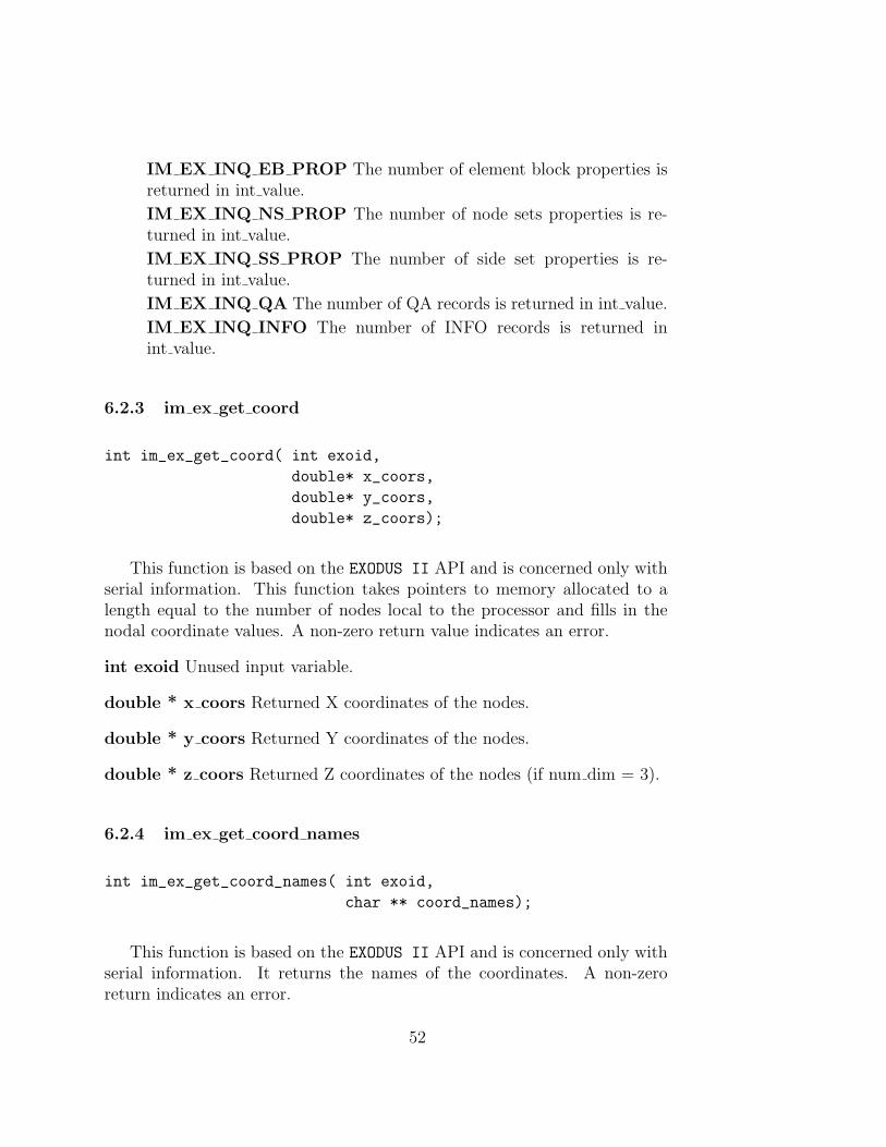
6.2.3 im ex get coord
int im_ex_get_coord( int exoid,
double* x_coors,
double* y_coors,
double* z_coors);
This function is based on the EXODUS II API and is concerned only withserial information. This function takes pointers to memory allocated to alength equal to the number of nodes local to the processor and fills in thenodal coordinate values. A non-zero return value indicates an error.
int exoid Unused input variable.
double * x coors Returned X coordinates of the nodes.
double * y coors Returned Y coordinates of the nodes.
double * z coors Returned Z coordinates of the nodes (if num dim = 3).
6.2.4 im ex get coord names
int im_ex_get_coord_names( int exoid,
char ** coord_names);
This function is based on the EXODUS II API and is concerned only withserial information. It returns the names of the coordinates. A non-zeroreturn indicates an error.
52

int exoid Unused input variable.
char ** coord names Returned vector pointing to num dim coord names.coord names can be declared and allocated as shown below.
char* coord_names[3];
for(int i = 0; i < num_dim; i++)
coord_names[i] = (char*)calloc((MAX_STR_LENGTH+1),sizeof(char));
6.2.5 im ex get map
int im_ex_get_map( int exoid,
int * element_map);
This function is based on the EXODUS II API and is concerned only withserial information. It loads the global element numbers into the providedstorage. A non-zero return value indicates an error.
int exoid Unused input variable.
int * element map On return this array holds the global element ids of theelements local to this processor. For a serial problem this runs sequentiallyfrom 1 to num elem. Memory sized to num elem must be allocated prior tomaking this call.
6.2.6 im ex get elem num map
int im_ex_get_elem_num_map( int exoid,
int * element_num_map);
For pamgen this function is identical to “im ex get map”.
int exoid Unused input variable.
int * element num map On return this array holds the global elementids of the elements local to this processor. For a serial problem these valuesrun sequentially from 1 to num elem. Memory sized to num elem must beallocated prior to making this call.
53

6.2.7 im ex get node num map
int im_ex_get_node_num_map( int exoid,
int * node_num_map);
This function is based on the EXODUS II API and is concerned only withserial information. It loads the global node numbers into the provided stor-age. A non-zero return indicates an error.
int exoid Unused input variable.
int * node num map On return this array holds the global node ids ofthe nodes local to this processor. For a serial problem this runs from 1 tonum nodes. Memory sized to num nodes must be allocated prior to makingthis call.
6.2.8 im ex get elem blk ids
int im_ex_get_elem_blk_ids( int exoid,
int * elem_blk_ids);
This function is based on the EXODUS II API and is concerned only withserial information. It loads the element block ids into the provided storage.A non-zero return value indicates an error.
int exoid Unused input variable.
int * elem blk ids On return this array holds the ids of the element blockson this processor. For pamgen meshes the element block ids across the entireproblem will run sequentially from 1 to num elem blk. On any particularprocessor of a parallel mesh any set of the global element blocks may bepresent. Storage sized to num elem blk must be allocated prior to makingthis call.
6.2.9 im ex get elem block
int im_ex_get_elem_block( int exoid,
int elem_blk_id,
54

char * elem_type,
int * num_elem_this_blk,
int * num_nodes_per_elem,
int * num_attr);
This function is based on the EXODUS II API and is concerned onlywith serial information. It provides information about the requested elementblock. Review of the conventions documented in the EXODUS II manual isthe most effective way to understand the mesh storage and retrieval. Underthe EXODUS II convention, a finite element mesh is composed of one or moreblocks of elements. Each block contains elements of the same type. Within ablock, all elements have the same number of nodes and the same connectivityconvention. The number of nodes is stored explicitly, and the connectivityconvention is called out by a string. This string corresponds to a table ofconventional element connectivities in the EXODUS II manual. A non-zeroreturn value indicates an error.
int exoid Unused input variable.
int elem blk id Input variable specifying the id of the block for whichinformation is requested. This id must be one of the values in the elem blk idsarray.
char * elem type On return this variable holds one of the standard EXODUS
II element types as a string. The element type pointer must be allocatedas length MAX STR LENGTH+1. For pamgen the stored value will beQUAD in 2D or HEX in 3D.
int * num elem this blk On return this variable holds the number of ele-ments in this block.
int * num nodes per elem On return this variable holds the number ofnodes per element for the elements in this block.
int * num attr On return this variable holds the number of attributes forthis block for pamgen this is always 0.
6.2.10 im ex get elem conn
int im_ex_get_elem_conn( int exoid,
55

int elem_blk_id,
int * connect);
This function is based on the EXODUS II API and is concerned only withserial information. It fills the storage pointed to by connect with the con-nectivity of the elements in the block referred to by elem blk id. A non-zeroreturn value indicates an error.
int exoid Unused input variable.
int elem blk id Input variable specifying the id of the block for whichinformation is requested. This id must be one of the values in the elem blk idsarray.
int * connect On return the storage pointed to by connect holds theconnectivity for the requested block. Connect must point to storage sizedto num elem this block*num nodes per elem. Connect holds (in the orderspecified by the EXODUS II convention) the nodes of each element in the spec-ified block. The first element’s connectivity begins at an offset of 0 and thenth element’s connectivity begins at an offset of n*num nodes per element.The EXODUS II standard specifies that the indices of the connectivity arenumbered from 1 so that in order to retrieve the coordinates of an element’snodes the indices given in connect must be decrimented by 1.
6.2.11 im ex get node set ids
int im_ex_get_node_set_ids( int exoid,
int * node_set_ids);
This function is based on the EXODUS II API and is concerned only withserial information. It loads the node set ids into the provided storage. Nodeset ids are specified in the string passed to the Create Pamgen Mesh function.By convention they must be non-zero and positive. A non-zero return valueindicates an error.
int exoid Unused input variable.
int * node set ids On return this array holds the ids of the node sets onthis processor. Storage sized to num node sets must be allocated prior tomaking this call.
56

6.2.12 im ex get node set param
int im_ex_get_node_set_param( int exoid,
int node_set_id,
int * num_nodes_in_node_set,
int * num_df_in_node_set);
This function is based on the EXODUS II API and is concerned only withserial information. It function provides sizing information for node set data.A non-zero return value indicates an error.
int exoid Unused input variable.
int node set id Input variable specifying the id of the node set for whichinformation is requested. This id must be one of the values in the node set idsarray.
int * num nodes in node set On return this variable is set to the numberof nodes in the specified node set.
int * num df in node set On return this variable is set to the numberof df in the specified node set. Distribution factors are scalar values linkedto the members of node sets or side sets. pamgen does not produce anydistribution factors on node sets or side sets. For pamgen this will be 0.
6.2.13 im ex get node set
int im_ex_get_node_set( int exoid,
int node_set_id,
int * node_set_node_list);
This function is based on the EXODUS II API and is concerned only withserial information. On return the provided storage is populated with thelocal nodes of the node set.
int exoid Unused input variable.
int node set id Input variable specifying the id of the node set for whichinformation is requested. This id must be one of the values in the node set idsarray.
57

int * node set node list On return this array holds the local ids of thenodes in the node set. The ids are numbered from 1. Storage must be sizedfor num nodes in nodeset.
6.2.14 im ex get side set ids
int im_ex_get_side_set_ids( int exoid,
int * side_set_ids);
This function is based on the EXODUS II API and is concerned only withserial information. It loads the side set ids into the provided storage. Side setids are specified in the string passed to the Create Pamgen Mesh function.By convention they must be non-zero and positive. A non-zero return valueindicates an error.
int exoid Unused input variable.
int * side set ids On return this array holds the ids of the side sets on thisprocessor. Storage sized to num side sets must be allocated prior to makingthis call.
6.2.15 im ex get side set param
int im_ex_get_side_set_param( int exoid,
int side_set_id,
int * num_sides_in_side_set,
int * num_df_in_side_set);
This function is based on the EXODUS II API and is concerned only withserial information. It provides sizing information for side set data. A non-zero return value indicates an error.
int exoid Unused input variable.
int side set id Input variable specifying the id of the side set for whichinformation is requested. This id must be one of the values in the side set idsarray.
58

int * num sides in side set On return this variable is set to the numberof sides in the specified side set.
int * num df in side set On return this variable is set to the number of dfin the specified side set. Distribution factors are scalar values linked to themembers of node sets or side sets. pamgen does not produce any distributionfactors on node sets or side sets. For pamgen this will be 0.
6.2.16 im ex get side set
int im_ex_get_side_set( int exoid,
int side_set_id,
int * side_set_element_list,
int * side_set_side_list);
This function is based on the EXODUS II API and is concerned only withserial information. It populates storage that specifies the sides of elementsthat are in a particular side set. The EXODUS II convention specifies a side bylisting an element id and the side of that element that is in the sideset. Thisinformation is provided in two corresponding arrays of equal length. Thesides specify a set of nodes on the element by reference to element topologytables in the EXODUS II manual. A non-zero return value indicates an error.
int exoid Unused input variable.
int side set id Input variable specifying the id of the side set for whichinformation is requested. This id must be one of the values in the side set idsarray.
int * side set element list On return this array holds the local ids ofthe elements having sides in the side set. Storage must be sized fornum sides in sideset.
int * side set side list On return this array holds the sides that are in theside set. Storage must be sized for num sides in sideset.
6.2.17 im ex get qa
int im_ex_get_qa( int exoid,
59

char * qa_record[][4]);
This function is based on the EXODUS II API and is concerned only withserial information. It populates previously allocated qa record storage withQuality Assurance (QA) information. By convention the four components ofeach record are:
1. The analysis code name
2. The analysis code QA descriptor
3. The analysis time
4. The analysis date
pamgen will return “PAMGEN”, “Parallel Mesh Generator” and then twocopies of the date and time. A non-zero return value indicates an error.
int exoid Unused input variable.
char * qa record[][4] Previously allocated storage that is filled with QArecords. The memory may be allocated as shown below.
char * qa_record[10][4];
for(int i = 0; i < 10; i++)
for(int j=0; j<4; j++) qa_record[i][j] = (char*)malloc(MAX_STR_LENGTH+1);
6.2.18 im ex get info
int im_ex_get_info( int exoid,
char ** info_record);
This function is based on the EXODUS II API and is concerned only withserial information. It populates previously allocated info record storage. Anon-zero return value indicates an error.
int exoid Unused input variable.
char ** info record Previously allocated storage into which info recordsare copied. At present for pamgen num info records is zero. Memory shouldwould be allocated as shown below.
60

char ** info_record;
info_record = (char**)malloc(num_info_records*sizeof(char*));
for(int i = 0; i < num_info_records; i++)
info_record[i] = (char*)malloc(MAX_STR_LENGTH+1);
6.2.19 im ne get init global
This function is adapted from the NEMESIS API. It is typically the first func-tion called when gathering information about the parallel nature of the mesh.It retrieves the mesh sizing information for the complete mesh. A non-zeroreturn value indicates an error.
int im_ne_get_init_global( int neid,
int *num_nodes_global,
int *num_elems_global,
int *num_elem_blks_global,
int *num_node_sets_global,
int *num_side_sets_global );
int neid Unused input variable.
int * num nodes global On return this variable is set to the total numberof nodes in the mesh.
int * num elems global On return this variable is set to the total numberof elements in the mesh.
int * num elem blks global On return this variable is set to the totalnumber of element blocks in the mesh.
int * num node sets global On return this variable is set to the totalnumber of node sets in the mesh.
int * num side sets global On return this variable is set to the total num-ber of side sets in the mesh.
61

6.2.20 im ne get init info
This function is adapted from the NEMESIS API. It retrieves informationabout the decomposition of the mesh. A non-zero return value indicates anerror.
int im_ne_get_init_info( int neid,
int *num_proc,
int *num_proc_in_file,
char *file_type);
int neid Unused input variable.
int *num proc On return this variable is filled with the total number ofprocessors over which the mesh is spread.
int *num proc in file On return this variable is filled with the number ofprocessors for which mesh is available via query. This value will always be 1when using pamgen.
char *file type Unused variable should be sized as shown below.
char file_type [2];
6.2.21 im ne get eb info global
int im_ne_get_eb_info_global( int neid,
int *el_blk_ids_global,
int *el_blk_cnts_global);
This function is adapted from the NEMESIS API. It retrieves the elementblock ids from the entire mesh as well as the sizes of each of these elementblocks. A non-zero return value indicates an error.
int neid Unused input variable.
int *el blk ids global On return this array holds the element block ids forthe entire mesh. It must be sized to hold num elem blks global integers.
62

int *el blk cnts global On return this array holds the number of ele-ments in each element block of the entire mesh. It must be sized to holdnum elem blks global integers.
6.2.22 im ne get ns param global
int im_ne_get_ns_param_global(int neid,
int *ns_ids_global,
int *ns_n_cnt_global,
int *ns_df_cnt_global);
This function is adapted from the NEMESIS API. It retrieves node setinformation for the entire mesh. A non-zero return value indicates an error.
int neid Unused input variable.
int *ns ids global On return this array holds the node set ids for the entiremesh. It must be sized to hold num node sets global integers.
int *ns n cnt global On return this array holds the number of nodes in eachnode set for the entire mesh. It must be sized to hold num node sets globalintegers.
int *ns df cnt global On return this array holds the number of nodeset distribution factors for the entire mesh. It must be sized to holdnum node sets global integers. For pamgen the number of distribution fac-tors for each node set will be 0.
6.2.23 im ne get ss param global
int im_ne_get_ss_param_global(int neid,
int *ss_ids_global,
int *ss_s_cnt_global,
int *ss_df_cnt_global);
This function is adapted from the NEMESIS API. It retrieves side setinformation for the entire mesh. A non-zero return value indicates an error.
int neid Unused input variable.
63

int *ss ids global On return this array holds the side set ids for the entiremesh. It must be sized to hold num side sets global integers.
int *ss s cnt global On return this array holds the number of sides in eachside set for the entire mesh. It must be sized to hold num side sets globalintegers.
int *ss df cnt global On return this array holds the number of sideset distribution factors for the entire mesh. It must be sized to holdnum side sets global integers. For pamgen the number of distribution fac-tors for each side set will be 0.
6.2.24 im ne get loadbal param
int im_ne_get_loadbal_param( int neid,
int *num_internal_nodes,
int num_border_nodes,
int *num_external_nodes,
int *num_internal_elems,
int *num_border_elems,
int *num_node_cmaps,
int *num_elem_cmaps,
int proc);
This function is adapted from the NEMESIS API. On return its argu-ments are filled with sizing information for processor communication data.This information is the first step in gathering all the information required toconstruct communication protocols between adjacent regions of decomposedmesh. A non-zero return value indicates an error.
int neid Unused input variable.
int * num internal nodes On return this variable is filled with the numberof nodes that are local to the mesh on this processor.
int * num border nodes On return this variable is filled with the numberof nodes that are common to the mesh on this processor and to adjacentprocessors.
int * num external nodes On return this variable is filled with the number
64

of nodes that are not local to this processor but are common to elements thatshare nodes with this processor.
int * num internal elems On return this variable is filled with the numberof elements that are local to this processor.
int * num border elems On return this variable is filled with the numberof elements that are not local to this processor but do share nodes withelements local to this processor.
int * num node cmaps On return this variable is filled with the numberof node communication maps.
int * num elem cmaps On return this variable is filled with the numberof element communication maps.
int proc Unused input variable.
6.2.25 im ne get elem map
int im_ne_get_elem_map( int neid,
int *elem_mapi,
int *elem_mapb,
int proc);
This function is adapted from the NEMESIS API. On return the the argu-ments of this function are populated with the internal and boundary elementmaps.
int neid Unused input variable.
int * elem mapi On return this variable is filled with the internal elementids. Storage sized to num internal elems must be supplied.
int * elem mapb On return this variable is filled with the border elementids. Storage sized to num border elems must be supplied.
int proc Unused input variable.
65

6.2.26 im ne get node map
int im_ne_get_node_map( int neid,
int *node_mapi,
int *node_mapb,
int *node_mape,
int proc);
This function is adapted from the NEMESIS API. On return the the argu-ments of this function are populated with the internal and boundary nodemaps.
int neid Unused input variable.
int * node mapi On return this variable is filled with the internal node ids.Storage sized to num internal nodes must be supplied.
int * node mapb On return this variable is filled with the border node ids.Storage sized to num border nodes must be supplied.
int * node mape On return this variable is filled with the external nodeids. Storage sized to num external nodes must be supplied.
int proc Unused input variable.
6.2.27 im ne get cmap params
int im_ne_get_cmap_params( int neid,
int *node_cmap_ids,
int *node_cmap_node_cnts,
int *elem_cmap_ids,
int *elem_cmap_elem_cnts,
int processor);
This function is adapted from the NEMESIS API. On return the storagepassed in its arguments is filled with the communication map ids and counts.A non-zero return value indicates an error.
int neid Unused input variable.
66

int * node cmap ids On return this storage is filled with the ids for eachnode communication map. Storage sized to num node cmap must be pro-vided.For pamgen these values will run from 0 to num node cmaps-1.
int * node cmap cnts On return this storage is filled with the number ofnodes in each node communication map. Storage sized to num node cmapmust be provided.
int * elem cmap ids On return this storage is filled with the ids for eachelement communication map. Storage sized to num elem cmap must be pro-vided. For pamgen these values will run from 0 to num elem cmaps-1.
int * elem cmap elem cnts On return this storage is filled with the num-ber of elements in each element communication map. Storage sized tonum elem cmap must be provided.
int proc Unused input variable.
6.2.28 im ne get node cmap
int im_ne_get_node_cmap( int neid,
int map_id,
int *node_ids,
int *proc_ids,
int processor);
This function is adapted from the NEMESIS API. On return the storagepassed in its arguments is filled with the node communication maps. A non-zero return value indicates an error.
int neid Unused input variable.
int map ids The id of the node communication map that is being queried.This must be one of the entries in node cmap ids.
int * node ids On return this storage is filled with the ids of nodes in themap. Storage must be sized to node cmap cnts[map id].
int * proc ids The processor id onto which the associated node in node idsmaps. Storage must be sized to node cmap cnts[map id].
67

int proc Unused input variable.
6.2.29 im ne get elem cmap
int im_ne_get_elem_cmap( int neid,
int map_id,
int *elem_ids,
int *side_ids,
int *proc_ids,
int processor);
This function is adapted from the NEMESIS API. On return the storagepassed in its arguments is filled with the element communication maps. Anon-zero return value indicates an error.
int neid Unused input variable.
int map ids The id of the element communication map that is beingqueried.This must be one of the entries in elem cmap ids.
int * elem ids On return this storage is filled with the ids of elements inthe map. Storage must be sized to elem cmap cnts[map id].
int * side ids On return this storage is filled with the ids sides of elementsin the map. Storage must be sized to elem cmap cnts[map id].
int * proc ids The processor id onto which the associated element inelem ids maps. Storage must be sized to elem cmap cnts[map id].
int proc Unused input variable.
68
6.3 Deleting a Mesh
6.3.1 Delete Pamgen Mesh
int Delete_Pamgen_Mesh(void);
This function clears and deletes the memory used to store mesh datacreated with the “Create Pamgen Mesh(...)” function. After this function iscalled “Create Pamgen Mesh(...)” may be called again to create a differentmesh.
69
A Runtime Compiler Functionality
The runtime compiler allows inclusion of double quoted (“ “) ’C’ languagestyle functions within unformatted input files. The functions are evaluatedduring program setup or execution to calculate independent solution vari-ables.
This provides the user with an endlessly flexible method for describingboundary conditions, initial conditions, source terms, material properties, orany other independent variable.
The specific variable names expected within runtime compiled functionsdepends on the host code and the context of the function use. In generalit should be remembered that the runtime functions return quantities bymodifying variables that are passed in by reference.
A.1 The RTC language
The RTC language can be thought of as a small subset of the C languagewith a couple minor modifications.
A.1.1 Operators
The RTC language has the following operators that work exactly as they doin C and have the same precedence as they do in C:
• + Addition
• − Subtration
• − Negation
• ∗ Multiplication
• / Division
• == Equality
• > Greater than
70

• < Less than
• >= Greater than or equal to
• <= Less than or equal to
• = Assignment
• || Logical or
• && Logical and
• ! = Inequality
• % Modulo
• ! Logical not
The following operators do not occur in the C language, but were added tothe RTC language for convenience:
• ^ Exponentiation
A.1.2 Control flow
The RTC language has the following control flow statements:
• for( expr ; expr ; expr ) { ... }
• while( expr ) { ... }
• if (expr) {...}
• else if (expr) {...}
• else {...}
These control flow statements work exactly as they do in C except that thecode blocks following a control flow statement MUST be enclosed withinbraces even if the block only consists of one line.
71

A.1.3 Line Structure
The line structure in the RTC language is the same as that of C. Expressionsend with a semicolon unless they are inside a control flow statement.
A.1.4 Variables
Declaring scalar variables in RTC is done exactly as it is done in C exceptthat only the following types are supported:
• int
• float
• double
• char
For scalars, variables can be declared and assigned all at once. Both of thefollowing approaches will work:
int myVar = 9;
OR
int myVar;
myVar = 9;
Arrays work a little differently in RTC than they do in C. There are no newor malloc operators, instead the user may declare dynamically sized arraysin the same manner as statically sized arrays. Also, in C all the values of anarray may be initialized at once by putting the values within braces. Thisis not supported in the RTC language. Users will have to loop through thearray and assign the values one by one. For example:
LEGAL:
int ia[x*y]; //Note: in C this would not be legal for non-const x,y
72

int ia2[3];
NOT LEGAL:
int ia[3] = {1, 2, 3};
Indexing arrays can be done using the index operator: array[expr] = ...;
Bounds checking is done at run time. If the bounds of an array are exceeded,it will dump an error to stdout.
A.1.5 Math
The following math.h functions are available in RTC:
• asin(arg) : returns the arc sine of arg
• acos(arg) : returns the arc cosine of arg
• atan(arg) : returns the arc tangent of arg
• atan2(y, x): returns the arc tangent of y/x
• sin(arg) : returns the sine of arg
• cos(arg) : returns the cosine of arg
• tan(arg) : returns the tangent of arg
• sqrt(arg) : returns the square root of arg
• exp(arg) : returns the natural logarithm base e raised to the arg power
• sinh(arg) : returns the hyperbolic sine of arg
• cosh(arg) : returns the hyperbolic cosine of arg
• tanh(arg) : returns the hyperbolic tangent of arg
• log(arg) : returns the natural logarithm for arg
• log10(arg) : returns the base 10 logarithm for arg
73

• rand(arg) : returns a system-generated random integer between 0 andRAND MAX using seed arg
• fabs(arg) : returns the absolute value of arg
• pow(b, e) : returns b to the e power (Note: the Exponentiation operatoris available)
• j0(arg) : Bessel function of order zero
• j1(arg) : Bessel function of order one
• i0(arg) : Modified Bessel function of order zero
• i1(arg) : Modified Bessel function of order one
• erf(arg) : Error function
• erfc(arg) : Complementary error function (1.0 - erf(x))
• gamma(arg) : returns Γ(arg)
A.1.6 Strings
The user may pass quoted strings as arguments to functions. Note: it maybe necessary to escape-out the double quotes so that they do not confuse theinput-file parser. See printf section below for an example.
A.1.7 Printf
The RTC printf method is called just like its C counterpart. The first ar-gument is a quoted character string. This string will contain the % symbolwhich will tell RTC to output the corresponding argument. The only differ-ence between RTC’s printf and C’s printf is that in RTC’s version, a typecharacter after the % is unnecessary. For example, inside an RTC methodthe following is appropriate:
printf(\"One:% Two:% Three:% \", 5-4, 2.0e0, ’c’);\n\
Which would generate this output: One:1 Two:2 Three:c
74

A.1.8 Comments
The traditional C-comment mechanism may be used inside RTC functions.Use /* to begin a comment and */ to end the comment.
A.1.9 Unsupported Features
Implementing the entire C-language was well beyond the intent of RTC.Features that were too difficult or did not add enough value have been leftout. The following is a list of common C features that are unsupported inRTC:
• There are no ++ or −− operators. Use i = i + 1 instead of + + i
• Structs
• Pointers
• Instant array initialization: int array[5] = 1,2,3,4,5;
• Case statements
• Casting
• Labels and gotos
• Function definition/declaration
• stdio
• Keywords: break, continue, const, enum, register, return, sizeof, type-def, union, volatile, static.
75

B read mesh to memory
This appendix lists an example of the “C” source code that an applicationlinked to pamgen would use to read a finite element mesh description frompamgen.
/*****************************************************************************/void read_mesh_to_memory()/*****************************************************************************/{
int im_exoid = 0;int idum = 0;float fdum;
mss.bptr[0] = mss.buffer[0];mss.bptr[1] = mss.buffer[1];mss.bptr[2] = mss.buffer[2];
for(int i = 0; i < 100; i++)for(int j=0; j<4; j++) mss.qaRecord[i][j] = (char*)malloc(MAX_STR_LENGTH+1) ;
char * cdum = NULL;int error = 0;int id = 0;error += im_ex_get_init ( id,
mss.title,&mss.num_dim,&(mss.num_nodes),&mss.num_elem,&mss.num_elem_blk,&mss.num_node_sets,&mss.num_side_sets);
error += im_ex_inquire(id, IM_EX_INQ_NS_NODE_LEN, (int*)&mss.num_node_set_nodes,&fdum, cdum);
error += im_ex_inquire(id, IM_EX_INQ_NS_DF_LEN, (int*)&mss.num_node_set_dfs,&fdum, cdum);
error += im_ex_inquire(id, IM_EX_INQ_SS_ELEM_LEN, (int*)&mss.num_side_set_elements,&fdum, cdum);
error += im_ex_inquire(id, IM_EX_INQ_SS_NODE_LEN, (int*)&mss.num_side_set_nodes,
76

&fdum, cdum);error += im_ex_inquire(id, IM_EX_INQ_SS_DF_LEN, (int*)&mss.num_side_set_dfs,
&fdum, cdum);
// // get version number
error += im_ex_inquire(id, IM_EX_INQ_API_VERS, &idum, &fdum, cdum);
mss.version_number = (double) fdum;
mss.version = (int) mss.version_number;
// // get genesis-II parameters
error += im_ex_inquire(id, IM_EX_INQ_EB_PROP,(int*)&mss.num_block_properties,&fdum, cdum);
error += im_ex_inquire(id, IM_EX_INQ_NS_PROP,(int*)&mss.num_node_set_properties,&fdum, cdum);
error += im_ex_inquire(id, IM_EX_INQ_SS_PROP,(int*)&mss.num_side_set_properties,&fdum, cdum);
mss.coord = (double *)malloc(mss.num_nodes*mss.num_dim*sizeof(double));
error += im_ex_get_coord(id,mss.coord,mss.coord+mss.num_nodes,mss.coord+2*mss.num_nodes);
error += im_ex_get_coord_names (id, mss.bptr);
if (mss.num_elem){mss.element_order_map = (int *)malloc(mss.num_elem * sizeof(int));error += im_ex_get_map(id, mss.element_order_map);
if (mss.num_elem){mss.global_element_numbers = (int *)malloc(mss.num_elem*sizeof(int));error += im_ex_get_elem_num_map(id, mss.global_element_numbers);
77

}
if (mss.num_nodes){mss.global_node_numbers = (int *)malloc(mss.num_nodes * sizeof(int));error += im_ex_get_node_num_map(id, mss.global_node_numbers);
}
//block info
mss.block_id = (int *)malloc(mss.num_elem_blk*sizeof(int));mss.nodes_per_element = (int *)malloc(mss.num_elem_blk*sizeof(int));mss.element_attributes = (int *)malloc(mss.num_elem_blk*sizeof(int));mss.elements = (int *)malloc(mss.num_elem_blk*sizeof(int));mss.element_types = (char **)malloc(mss.num_elem_blk*sizeof(char *));mss.elmt_node_linkage = (int **)malloc(mss.num_elem_blk*sizeof(int*));
error += im_ex_get_elem_blk_ids(id, mss.block_id);
for(int i = 0; i < mss.num_elem_blk; i ++){mss.element_types[i] = (char *)malloc((MAX_STR_LENGTH + 1)*sizeof(char));error += im_ex_get_elem_block(id,
mss.block_id[i],mss.element_types[i],(int*)&(mss.elements[i]),(int*)&(mss.nodes_per_element[i]),(int*)&(mss.element_attributes[i]));
}
//connectivityfor(int b = 0; b < mss.num_elem_blk; b++){
mss.elmt_node_linkage[b] = (int*)malloc(mss.nodes_per_element[b]*mss.elements[b]*sizeof(int));
error += im_ex_get_elem_conn(id,mss.block_id[b],mss.elmt_node_linkage[b]);}
if(mss.num_node_sets){mss.node_set_id = (int *) malloc(mss.num_node_sets*sizeof(int));mss.num_nodes_in_node_set = (int *) malloc(mss.num_node_sets*sizeof(int));mss.node_set_nodes = (int **)malloc(mss.num_node_sets*sizeof(int*));mss.num_df_in_node_set = (int *) malloc(mss.num_node_sets*sizeof(int*));
78
error += im_ex_get_node_set_ids(id, mss.node_set_id);
for(int i = 0; i < mss.num_node_sets; i ++){error += im_ex_get_node_set_param(id, mss.node_set_id[i],
(int*)&mss.num_nodes_in_node_set[i],(int*)&mss.num_df_in_node_set[i]);
mss.node_set_nodes[i] = NULL;
if(mss.num_nodes_in_node_set[i]) {mss.node_set_nodes[i] =(int *)malloc(mss.num_nodes_in_node_set[i]*sizeof(int));error += im_ex_get_node_set(id,
mss.node_set_id[i],mss.node_set_nodes[i]);
}}
}
//side setsif(mss.num_side_sets){mss.side_set_id = (int*)malloc(mss.num_side_sets*sizeof(int));mss.num_elements_in_side_set = (int*)malloc(mss.num_side_sets*sizeof(int));mss.num_df_in_side_set = (int*)malloc(mss.num_side_sets*sizeof(int));mss.side_set_elements = (int**)malloc(mss.num_side_sets*sizeof(int *));mss.side_set_faces = (int **)malloc(mss.num_side_sets*sizeof(int*));
error += im_ex_get_side_set_ids(id, mss.side_set_id);for(int i = 0; i < mss.num_side_sets; i ++){
error += im_ex_get_side_set_param(id, mss.side_set_id[i],(int*)&mss.num_elements_in_side_set[i],(int*)&mss.num_df_in_side_set[i]);
int ne = mss.num_elements_in_side_set[i];mss.side_set_elements[i] = (int*)malloc(ne*sizeof(int));mss.side_set_faces[i] = (int*)malloc(ne*sizeof(int));if(ne){error += im_ex_get_side_set(id, mss.side_set_id[i],
mss.side_set_elements[i],mss.side_set_faces[i]);
79

}}
}
error += im_ex_inquire(id, IM_EX_INQ_QA, (int*)&mss.num_qa_records, &fdum, cdum);
if(mss.num_qa_records)error += im_ex_get_qa(id,mss.qaRecord);
error += im_ex_inquire(id, IM_EX_INQ_INFO, (int*)&mss.num_info_records, &fdum, cdum);if(mss.num_info_records) {
mss.info_records = (char **)malloc(mss.num_info_records*sizeof(char *));for(int i = 0; i < mss.num_info_records; i ++){
mss.info_records[i] = (char *)malloc(MAX_STR_LENGTH+1);}error += im_ex_get_info(id, mss.info_records);
}
//nemesis data// global infoif ( im_ne_get_init_global(id, &mss.num_nodes_global, &mss.num_elems_global,
&mss.num_elm_blks_global, &mss.num_node_sets_global,&mss.num_side_sets_global) < 0 )
++error;
if ( im_ne_get_init_info(id,&mss.num_total_proc,&mss.num_proc_in_file, mss.type) < 0 )
++error;
mss.elem_blk_ids_global = (int*)malloc(mss.num_elm_blks_global*sizeof(int));mss.elem_blk_cnts_global = (int*)malloc(mss.num_elm_blks_global*sizeof(int));
if ( im_ne_get_eb_info_global(id,mss.elem_blk_ids_global,mss.elem_blk_cnts_global) < 0 )
++error;
mss.ns_ids_global = (int *)malloc(mss.num_node_sets_global*sizeof(int));mss.ns_cnts_global = (int *)malloc(mss.num_node_sets_global*sizeof(int));
80
mss.ns_df_cnts_global = (int *)malloc(mss.num_node_sets_global*sizeof(int));mss.ss_ids_global = (int *)malloc(mss.num_side_sets_global*sizeof(int));mss.ss_cnts_global = (int *)malloc(mss.num_side_sets_global*sizeof(int));mss.ss_df_cnts_global = (int *)malloc(mss.num_side_sets_global*sizeof(int));
if ( mss.num_node_sets_global > 0 ) {if ( im_ne_get_ns_param_global(id,mss.ns_ids_global,mss.ns_cnts_global,
mss.ns_df_cnts_global) < 0 )++error;}
if ( mss.num_side_sets_global > 0 ) {if ( im_ne_get_ss_param_global(id,mss.ss_ids_global,mss.ss_cnts_global,
mss.ss_df_cnts_global) < 0 ) ++error;}
//parallel infoif ( im_ne_get_loadbal_param( id,
&mss.num_internal_nodes,&mss.num_border_nodes,&mss.num_external_nodes,&mss.num_internal_elems,&mss.num_border_elems,&mss.num_node_comm_maps,&mss.num_elem_comm_maps,0/*unused*/ ) < 0 )++error;
mss.internal_elements = (int *)malloc(mss.num_internal_elems*sizeof(int));mss.border_elements = (int *)malloc(mss.num_border_elems*sizeof(int));mss.internal_nodes = (int *)malloc(mss.num_internal_nodes*sizeof(int));mss.border_nodes = (int *)malloc(mss.num_border_nodes*sizeof(int));mss.external_nodes = (int *)malloc(mss.num_external_nodes*sizeof(int));
if ( im_ne_get_elem_map( id,mss.internal_elements,mss.border_elements,0/* not used proc_id*/ ) < 0 )++error;
if ( im_ne_get_node_map( id,mss.internal_nodes,mss.border_nodes,mss.external_nodes,0/* not used proc_id*/ ) < 0 )++error;
81

if(mss.num_node_comm_maps > 0){
mss.node_cmap_node_cnts = (int*) malloc(mss.num_node_comm_maps*sizeof(int));mss.node_cmap_ids = (int*) malloc(mss.num_node_comm_maps*sizeof(int));mss.comm_node_ids = (int**)malloc(mss.num_node_comm_maps*sizeof(int*));mss.comm_node_proc_ids = (int**)malloc(mss.num_node_comm_maps*sizeof(int*));
mss.elem_cmap_elem_cnts = (int*) malloc(mss.num_elem_comm_maps*sizeof(int));mss.elem_cmap_ids = (int*) malloc(mss.num_elem_comm_maps*sizeof(int));mss.comm_elem_ids = (int**)malloc(mss.num_elem_comm_maps*sizeof(int*));mss.comm_side_ids = (int**)malloc(mss.num_elem_comm_maps*sizeof(int*));mss.comm_elem_proc_ids = (int**)malloc(mss.num_elem_comm_maps*sizeof(int*));
if ( im_ne_get_cmap_params( id,mss.node_cmap_ids,(int*)mss.node_cmap_node_cnts,mss.elem_cmap_ids,(int*)mss.elem_cmap_elem_cnts,0/*not used proc_id*/ ) < 0 )++error;
for(int j = 0; j < mss.num_node_comm_maps; j++) {mss.comm_node_ids[j] = (int *)malloc(mss.node_cmap_node_cnts[j]*sizeof(int));mss.comm_node_proc_ids[j] = (int *)malloc(mss.node_cmap_node_cnts[j]*sizeof(int));if ( im_ne_get_node_cmap( id,
mss.node_cmap_ids[j],mss.comm_node_ids[j],mss.comm_node_proc_ids[j],0/*not used proc_id*/ ) < 0 )++error;
}
for(int j = 0; j < mss.num_elem_comm_maps; j++) {mss.comm_elem_ids[j] = (int *)malloc(mss.elem_cmap_elem_cnts[j]*sizeof(int));mss.comm_side_ids[j] = (int *)malloc(mss.elem_cmap_elem_cnts[j]*sizeof(int));mss.comm_elem_proc_ids[j] = (int *)malloc(mss.elem_cmap_elem_cnts[j]*sizeof(int));if ( im_ne_get_elem_cmap( id,
mss.elem_cmap_ids[j],mss.comm_elem_ids[j],mss.comm_side_ids[j],
82
mss.comm_elem_proc_ids[j],0 /*not used proc_id*/ ) < 0 )++error;
}//loop over num_elem_co}
}}
83

References
[1] G. L. Hennigan, M. St. John, and J. N. Shadid. NEMESIS I: A setof functions for describing unstructured finite-element data on parallelcomputers. Technical report, Sandia National Laboratories, Albuquerque,NM, May 1998.
[2] L. A. Schoof and V. R. Yarberry. EXODUS II: A Finite Element DataModel. Technical report SAND92-2137, Sandia National Laboratories,Albuquerque, NM, November 1995.
84

Index
Block IDs, 18Boundary Conditions, 34Brick, 32
Cylindrical, 23
Decomposition Strategy, 42Dimensionality, 17
Geometry and Topology, 19
Nodesets, 34
Radial, 25Radial Trisection, 25Rectilinear, 19
Set Assign, 34Sidesets, 34Spherical, 21
Trisection, 25
User Defined Element Density, 40User Defined Geometry Transformation, 37
85

DISTRIBUTION:
1 MS 0321J. Peery, 1400
1 MS 0384A. C. Ratzl, 1500
1 MS 0826D. K. Gartling, 1500
1 MS 1318D. E. Womble, 1410
1 MS 0321J. L. Mitchiner, 1410
1 MS 0380H. S. Morgan, 1540
1 MS 0380G. D. Sjaardema, 1541
1 MS 0382M. W. Glass, 1541
1 MS 0836R. E. Hogan, 1514
1 MS 0370J. H. Strickland, 1434
1 MS 1322J. B. Aidun, 1435
1 MS 1318S. S. Collis, 1416
1 MS 1416M. A. Heroux, 1416
1 MS 1318K. D. Devine, 1416
1 MS 0378R. M. Summers, 1431
1 MS 0378S. Carroll, 1431
1 MS 0378D. M. Hensinger, 1431
1 MS 0378A. C. Robinson, 1431
1 MS 0378R. R. Drake, 1431
1 MS 0378O. E. Strack, 1431
1 MS 0378D. A. Labreche, 1431
1 MS 0378C. B. Luchini, 1431
1 MS 0378S. J. Mosso, 1431
1 MS 0378S. V. Petney, 1431
1 MS 0378M. K. Wong, 1431
1 MS 0975J. M. Foucar, 5522
1 MS 1318T. A. Gardiner, 9326
1 MS 0899Technical Library, 9536
86
(electronic copy)