Embed Size (px)
Citation preview
PAPER CRAFT
2003.10.25
Assembly Instructions
Assembly instructions: Sixteen A4-sized sheets.
Paper craft: Twenty-one A4-sized sheets with 156 parts in all
These instructions apply only to the "TMAX." These Paper Craft parts areeasier to work with when printed out on strong, thick paper (like postcard stock).
In creating these Paper Craft models we use 135kg Kent paper stock (0.18mm).
Thank you for downloading the "TMAX"paper craft model. By simplyfollowing this manual while referring to the names and numbers shownon the parts sheets, you can assemble an authentic-looking replica of the TMAX.
Note
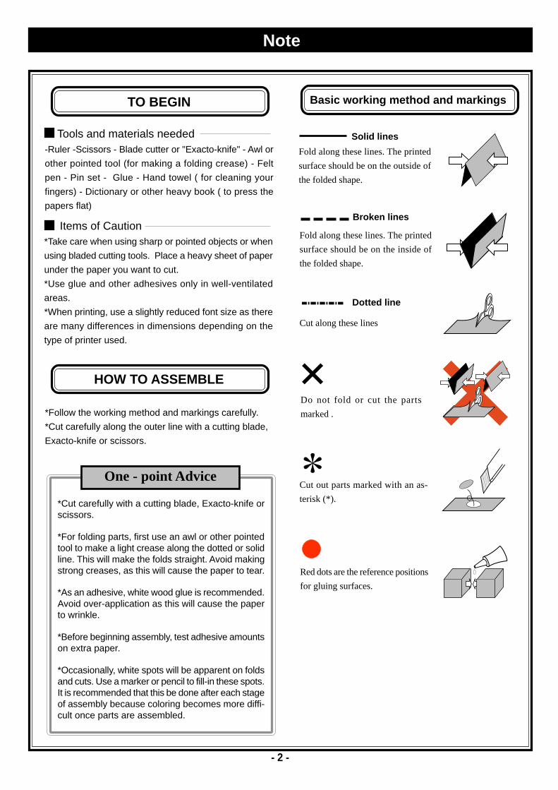
TO BEGIN
Items of Caution*Take care when using sharp or pointed objects or when
using bladed cutting tools. Place a heavy sheet of paper
under the paper you want to cut.
*Use glue and other adhesives only in well-ventilated
areas.
*When printing, use a slightly reduced font size as there
are many differences in dimensions depending on the
type of printer used.
Tools and materials needed-Ruler -Scissors - Blade cutter or "Exacto-knife" - Awl or
other pointed tool (for making a folding crease) - Felt
pen - Pin set - Glue - Hand towel ( for cleaning your
fingers) - Dictionary or other heavy book ( to press the
papers flat)
HOW TO ASSEMBLE
*Follow the working method and markings carefully.
*Cut carefully along the outer line with a cutting blade,
Exacto-knife or scissors.
*Cut carefully with a cutting blade, Exacto-knife orscissors.
*For folding parts, first use an awl or other pointedtool to make a light crease along the dotted or solidline. This will make the folds straight. Avoid makingstrong creases, as this will cause the paper to tear.
*As an adhesive, white wood glue is recommended.Avoid over-application as this will cause the paperto wrinkle.
*Before beginning assembly, test adhesive amountson extra paper.
*Occasionally, white spots will be apparent on foldsand cuts. Use a marker or pencil to fill-in these spots.It is recommended that this be done after each stageof assembly because coloring becomes more diffi-cult once parts are assembled.
One - point Advice
Basic working method and markings
Fold along these lines. The printed
surface should be on the outside of
the folded shape.
Solid lines
Dotted line
Fold along these lines. The printed
surface should be on the inside of
the folded shape.
Broken lines
Cut out parts marked with an as-
terisk (*).
Cut along these lines
Red dots are the reference positions
for gluing surfaces.
- 2 -
Do not fold or cut the parts
marked .

- 3 -
A-1 A-2
A-3
A-4
A-6
A-7
A-5
A-1
A-2
Reference photo
Sheet A, 7 parts in totalFront Cowl
First, assemble each component by following theworking method and markings. Then, refer to the il-lustration and photos below to glue the parts together.
Indication ofWorking Methods Fold or Curve Glue
1 Assembling the Front Cowl
Please use the dots on each component as reference when gluing surfaces.Fold each relevant part according to the assembly symbols.
- 4 -
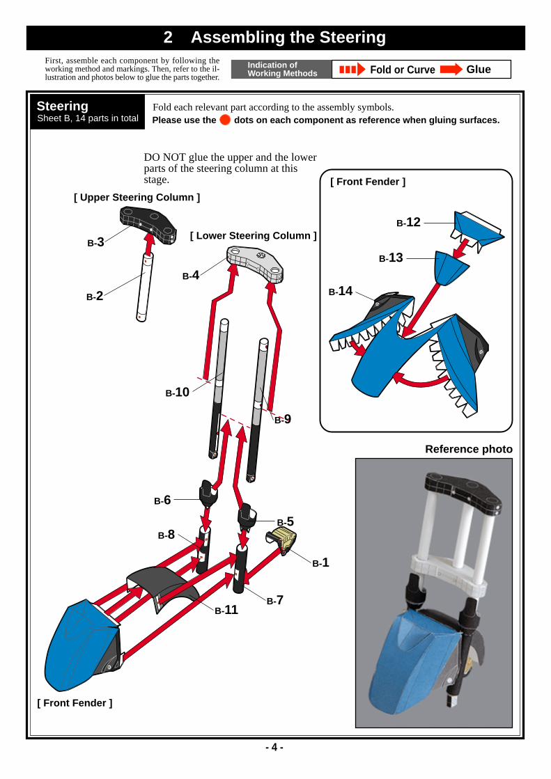
B-12
B-2
B-3
B-4
B-10
B-6
B-8
B-9
B-5
B-1
B-7B-11
B-13
B-14
DO NOT glue the upper and the lowerparts of the steering column at thisstage.
[ Upper Steering Column ]
[ Lower Steering Column ]
[ Front Fender ]
[ Front Fender ]
Reference photo
SteeringSheet B, 14 parts in total
Fold each relevant part according to the assembly symbols.Please use the dots on each component as reference when gluing surfaces.
First, assemble each component by following theworking method and markings. Then, refer to the il-lustration and photos below to glue the parts together.
Indication ofWorking Methods Fold or Curve Glue
2 Assembling the Steering

- 5 -
C-1
C-2
C-3C-4
C-5
D-7
D-4D-8
D-2
D-3
D-5D-6
D-1
FrameSheet C, 5 parts in total
First, assemble each component by following theworking method and markings. Then, refer to the il-lustration and photos below to glue the parts together.
Indication ofWorking Methods Fold or Curve Glue
3 Assembling the Frame & Rear Fender
Fold each relevant part according to the assembly symbols.Please use the dots on each component as reference when gluing surfaces.
Rear FenderSheet D, 8 parts in total
Fold each relevant part according to the assembly symbols.Please use the dots on each component as reference when gluing surfaces.
Reference photo
Reference photo

- 6 -
E-6
E-7
E-5
E-2
E-1
E-15
E-13
E-11
E-10
E-9E-3E-4
E-8
E-12
E-14
Rear ArmSheet E, 15 parts in total
First, assemble each component by following theworking method and markings. Then, refer to the il-lustration and photos below to glue the parts together.
Indication ofWorking Methods Fold or Curve Glue
4 Assembling the Rear Arm
Fold each relevant part according to the assembly symbols.Please use the dots on each component as reference when gluing surfaces.
Reference photo

- 7 -
F-3
F-4
F-2
F-1
G-2
G-3G-16
G-15
G-14
G-11G-12
G-13
G-4
G-1G-10
G-9
G-8
G-7 G-6
G-5
SeatSheet F, 4 parts in total
Fold each relevant part according to the assembly symbols.Please use the dots on each component as reference when gluing surfaces.
First, assemble each component by following theworking method and markings. Then, refer to the il-lustration and photos below to glue the parts together.
Indication ofWorking Methods Fold or Curve Glue
5 Assembling the Seat & Exhaust Pipes
Reference photo
Reference photo
Exhaust PipesSheet G, 16 parts in total
Fold each relevant part according to the assembly symbols.Please use the dots on each component as reference when gluing surfaces.

- 8 -
H-6H-4
H-7
H-3
H-5
H-2
H-1
H-13
H-14
H-12
H-10
H-11
H-9
H-8
H-15
Steering HandleSheet H, 7 parts in total
First, assemble each component by following theworking method and markings. Then, refer to the il-lustration and photos below to glue the parts together.
Indication ofWorking Methods Fold or Curve Glue
6 Assembling the Steering Handle & Stand
Fold each relevant part according to the assembly symbols.Please use the dots on each component as reference when gluing surfaces.
Reference photo
Reference photo
StandSheet H, 8 parts in total
Fold each relevant part according to the assembly symbols.Please use the dots on each component as reference when gluing surfaces.

- 9 -
I-8
I-5
I-9
I-1
I-13 I-2
I-6
I-11 I-10
I-3
I-4
I-12
I-7
Side CoversSheet I, 25 parts in total
First, assemble each component by following theworking method and markings. Then, refer to the il-lustration and photos below to glue the parts together.
Indication ofWorking Methods Fold or Curve Glue
7 Assembling the Side Covers -A
Fold each relevant part according to the assembly symbols.Please use the dots on each component as reference when gluing surfaces.
Reference photo

- 10 -
I-19(25)
I-16(21)I-14(22)
I-15(23)
I-18(24)
I-17(20)
Side CoversSheet I, 25 parts in total
Fold each relevant part according to the assembly symbols.Please use the dots on each component as reference when gluing surfaces.
First, assemble each component by following theworking method and markings. Then, refer to the il-lustration and photos below to glue the parts together.
Indication ofWorking Methods Fold or Curve Glue
8 Assembling the Side Covers -B
Assemble both side covers.The diagram shows how the leftside cover looks.The numbers within the parentheses indi-cate the parts for the right side cover.
Reference photo

- 11 -
J-11
J-14
J-16
J-15
J-4
J-1
J-10
J-9
J-8
J-6J-7
J-5
J-3J-2
J-17
J-12
J-13
Crank CaseSheet J, 17 parts in total
First, assemble each component by following theworking method and markings. Then, refer to the il-lustration and photos below to glue the parts together.
Indication ofWorking Methods Fold or Curve Glue
9 Assembling the Crank Case
Fold each relevant part according to the assembly symbols.Please use the dots on each component as reference when gluing surfaces.
Reference photo

- 12 -
K-6
K-5
K-2
K-7
K-3
K-1
K-8
K-14
K-10
K-12
K-9
K-13K-11
K-15
K-4
Reference photo
Front TireSheet K, 15 parts in total
First, assemble each component by following theworking method and markings. Then, refer to the il-lustration and photos below to glue the parts together.
Indication ofWorking Methods Fold or Curve Glue
10 Assembling the Front Tire
Fold each relevant part according to the assembly symbols.Please use the dots on each component as reference when gluing surfaces.
*Glue the completed front wheel to the assembled front tire.
[Front tire]
[Front wheel]
- 13 -
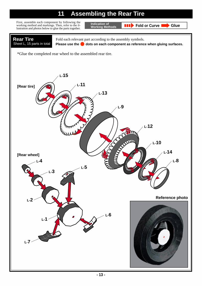
L-8
L-15
L-11
L-13
L-9
L-12
L-10
L-14
L-4
L-3
L-2
L-1
L-5
L-6
L-7
Reference photo
Rear TireSheet L, 15 parts in total
First, assemble each component by following theworking method and markings. Then, refer to the il-lustration and photos below to glue the parts together.
Indication ofWorking Methods Fold or Curve Glue
11 Assembling the Rear Tire
Fold each relevant part according to the assembly symbols.Please use the dots on each component as reference when gluing surfaces.
[Rear tire]
*Glue the completed rear wheel to the assembled rear tire.
[Rear wheel]

1
1
2
3
4
4
4
5
5
6
7
8
8
9
10
11
12
13
13
6
7
- 14 -
Please use the dots on each component as reference when gluing surfaces.
glue the assembled parts in numericalorder through .
Assembly Instructions
12 Finish
1 13
Exhaust Pipe Rear Fender
Rear Tire
Rear Arm
Stand
Side Cover B
Crank CaseFrame
Steering Handle
Side Cover A
Front Tire
Front Cowl
Upper Steering Column
Lower Steering Column
Seat
Glue the side cover B to the frame.
Glue the rear arm to the crankcase.
Glue the crankcase to the frame.
Insert the frame into the side cover A, and glue the side covers
A and B.
Glue the side cover B to the rear fender.
Glue the exhaust to the crankcase and the rear fender.
Glue the seat to the frame and the rear fender.
Insert the upper steering column into the frame, and glue it to
the lower steering column.
Glue the front cowl to the side cover A.
Glue the rear tire to the rear arm.
Glue the front tire to the lower steering column.
Glue the steering handle to the side cover A.
Glue the stand to the crankcase.
1234
5678
910
11
1213
K-1K-2K-3K-4K-5
K-6K-7K-8K-9K-10
K-11K-12K-13K-14K-15
G-1G-2G-3G-4G-5
G-6G-7G-8G-9G-10
G-11G-12G-13G-14G-15
G-16
I-1I-2I-3I-4I-5I-6
I-7I-8I-9I-10I-11I-12
I-13I-14I-15I-16I-17I-18
I-19I-20I-21I-22I-23I-24
I-25
- 15 -
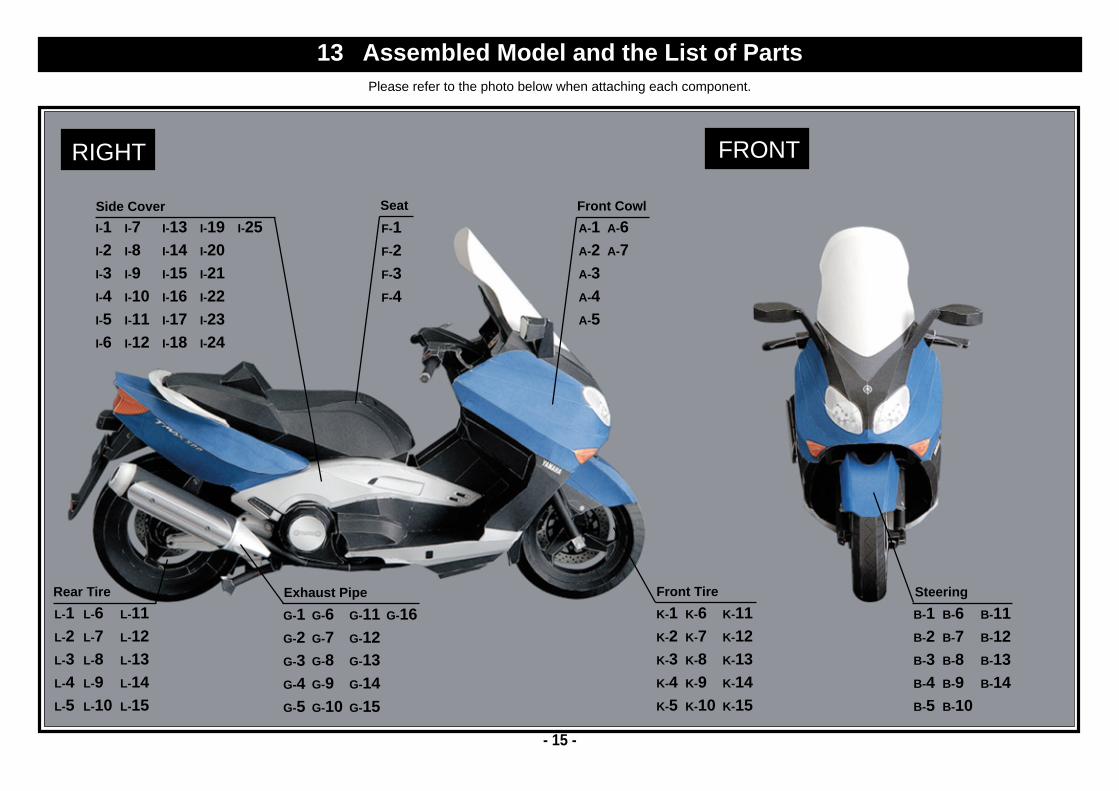
RIGHT FRONT
A-1A-2A-3A-4A-5
A-6A-7
F-1F-2F-3F-4
L-1L-2L-3L-4L-5
L-6L-7L-8L-9L-10
L-11L-12L-13L-14L-15
B-1B-2B-3B-4B-5
B-6B-7B-8B-9B-10
B-11B-12B-13B-14
Rear Tire Exhaust Pipe
Side Cover Front Cowl
SteeringFront Tire
Seat
13 Assembled Model and the List of PartsPlease refer to the photo below when attaching each component.

E-1E-2E-3E-4E-5
E-6E-7E-8E-9E-10
E-11E-12E-13E-14E-15
- 16 -
LEFT REAR
C-1C-2C-3C-4C-5
D-1D-2D-3D-4D-5D-6
D-7D-8
J-1J-2J-3J-4J-5J-6
J-7J-8J-9J-10J-11J-12
J-13J-14J-15J-16J-17
H-1H-2H-3H-4H-5
H-6H-7
H-8H-9H-10H-11H-12
H-13H-14H-15
Rear Fender
Rear ArmStand
Crank Case
Frame
Steering Handle
14 Assembled Model and the List of PartsPlease refer to the photo below when attaching each component.