Embed Size (px)
DESCRIPTION
Heat Transfer
Citation preview
7/18/2019 Paper Ed7 16
http://slidepdf.com/reader/full/paper-ed7-16 1/12
Heat Transfer Analysis of Convection andRadiation in a Triangular Fins Heat Exchanger
Qusay R. Al-Hagag Hameed K. Al Naffiey, Hayder Krady R .
Department of Mechanical Engineering, College of Engineering
University of Babylon1. Abstract
The effects of convection and radiation on triangular heat exchanger fins of a catalytic reactorare investigated. Heat is transferred by conduction along the n and dissipated fromthe surface by convection and radiation. The base of the n is maintained at avariable elevated temperature, while the tip loses heat due to convection andradiation. Due to symmetry and simplicity of analysis, one of the walls is considered.
A general nite dierence formulation, that accounts for free and forcedconvection and for radiative heat transfer with a simple model is developed topredict the temperature and rate of heat transfer along the n. In this study, theconvection heat transfer coecient is considered to be varying between(1!"#)W/m.! with air as the cooling medium. The temperature distri"ution of reactor surface is
estimated "y using finite difference method and the results are compared with the #$%&%' finiteelement code results.The temperature profiles of radiation show different aspects and it is found that the radiation term
has not effect on temperature profile, so the radiation can "e ignored in the case of forced convectionsystem. While it has a significant effect in the case of free convection system. n the other hand, thevalidity of thermal results for free and forced convection and radiation effect is good agreement "etweenthe results of the numerical solution and #$%&%' results.
Keywords / Heat Exca!ger, "i!s, Radiatio! , "ree a!d "orced
co!#ectio!,AN$%$&.
اخل
$% &'( )*+*- /01)20 3* 4567 8 9 ( %:;<=>0?10@520BC ( >;DE20-8FGF<J20KLM;NJ42-O10@520$;8PQK 0@8FR69 J520S;UV0QBWX3J>:;<=>0? 10@520Y4D9D;Z[$\ .]E8Z56?10@5209<=^6
98_3=2;PY4D:3`-Z^DE20 Q=6?10@520[209J52;P Q6 .S;UL0M;O\*+- 0* 23456 789:;<+ =8><+ ? 7 @3A B;CEF G H 7I>;<+ J 7 KE LMIJ6Q ,-/01)20Y4D 10))0Q9D;ZJ42-8=>6 .jP;=42;kO00)=/0[;>@P'#$%&%85=2 q;=^20M;O&QO36K;1M?10@520Y4D 10)209D;ZJ20
$0 .C^DEJ20KG[;[:;<=>0?10@520-[)=J20B0*5N20Q0@=68PW/m.! ( 1N . (1#!$\K;[-1M?10@5208N6$0S;UV0j2K( ;J/- ( Z4=[8^8P;=^20)D @8FR6S( ;UV0Y4DK;[-1M?10@520B ;>9 J520]@<20;J^8PLxJOj2;J*&B-2;9J520[ .@520-8;^20
z@{|06)}R=20[-5_ ;=^20 -O10@520=2;529J520 @520 Q]@<20 Q @8FR6S;208$;}~;^*•B036)88P9520]M)209520Q0)=/;P[;>@P '#$%&%. q
'-Nome!clature$ymbol (escri)tio! *!it
# #rea m
O p %pecific heat capacity P/!g !
Q %hape factor Rl Satent heat capacity W/m ! Thermal conductivity W/m ! S Sength mU %u"R region num"er RV Xeat flux, W/mY
V Xeat generation rate per volume W/mY
% Qin gap mTc Temperature of casting surface ! Tm Temperature of mold (chill) surface !
T Temperature ! W Width of "ase m
7/18/2019 Paper Ed7 16
http://slidepdf.com/reader/full/paper-ed7-16 2/12
x distance m+ree symbols
ρ Density of material !g/mY
Z %tefanR [olti\man constant R] ^missivity of the surface. R
∆x Distance interval m
$ubscri)t
a am"ient " "asef fini,_ node pointsr radiations surface
-!troductio!
Xeat exchangers are commonly used in many fields of industry, which arecomposed of finned surfaces for dissipation of heat "y convection and radiation. Thecalculation of heat transfer of a cooling fin in heat exchanger system is the good
practical application of heat transfer. %uch fins are used to increase the cooling area ofsystem availa"le for heat transfer "etween metal walls and conducting fluid such asgases and liVuids "y 0ird et al. '2. `n a chemical process, the reactor at hottemperature is cooled using cooling fins. The coolant is the surrounding air. Xeattransfer in heat exchanger is dominated "y convection from the surfaces, although theconduction within the fin may also influence on the performance. # convenient methodto treat convection cooling is to use heat transfer coefficients, h, "y 3elty et al.1&&42.
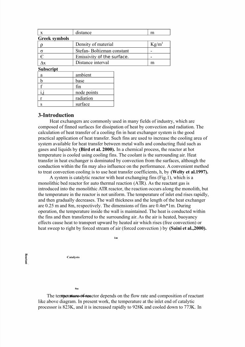
# system is catalytic reactor with heat exchanging fins (Qig.1), which is a
monolithic "ed reactor for auto thermal reaction (#T). #s the reactant gas isintroduced into the monolithic #T reactor, the reaction occurs along the monolith, "utthe temperature in the reactor is not uniform. The temperature of inlet end rises rapidly,and then gradually decreases. The wall thicness and the length of the heat exchangerare N.b m and m, respectively. The dimensions of fins are N.m1m. Duringoperation, the temperature inside the wall is maintained. The heat is conducted withinthe fins and then transferred to the surrounding air. #s the air is heated, "uoyancyeffects cause heat to transport upward "y heated air which rises (free convection) orheat sweep to right "y forced stream of air (forced convection ) "y $ai!i et al.,'2.
The temperature of reactor depends on the flow rate and composition of reactant
lie a"ove diagram. `n present wor, the temperature at the inlet end of catalytic processor is Y!, and it is increased rapidly to '! and cooled down to Y!. `n
7/18/2019 Paper Ed7 16
http://slidepdf.com/reader/full/paper-ed7-16 3/12
the present study, the effect of the convection and radiation has "een studied "y usingfinite difference method and #$%&%' finite element with triangular elements. Typicalvalues of h are given in Ta"le (1) "y %u!us A. 5e!gel,'42.
6able 1276y)ical #alues of co!#ectio! eat tra!sfer coefficie!t Type of convection h, W/m!
€ree convection of gases !#€ree convection of li‚uids "!"€orced convection ofgases
#!#
€orced convection ofli‚uids
#!
The ranges of heat transfer coefficient on the surface of the wall heat exchanger finsare varied from 1N to 1bN W/m!. The value for the heat transfer coefficient at the sideof reactor is approximated with a 1N W/m! for free convection. Qor forcedconvection, the heat transfer coefficient is approximated with a 1bN W/m!. `n this
system, the heat transfer coefficient is defined as a constant for a convenience ofcalculation. Typical material properties of %teel #`%` YN are ta"ulated in Ta"le()6able '278aterial 9ro)erties
Uaterial W/m .! g/mY ρ P/g.! pC
%teel #`%` YN .b bN N
:. 8atematical modelThe analysis is "ased on the following assumptionsj1.Two dimensional and steady state heat transfer model,
.#ll the physical properties are assumed to "e constant,Y.There is a perfect contact "etween the wall and the extended surfaces,. The radiation effect is significant,b. The fluid is considered incompressi"le with constant properties,. There are no heat sources within the fin itself.
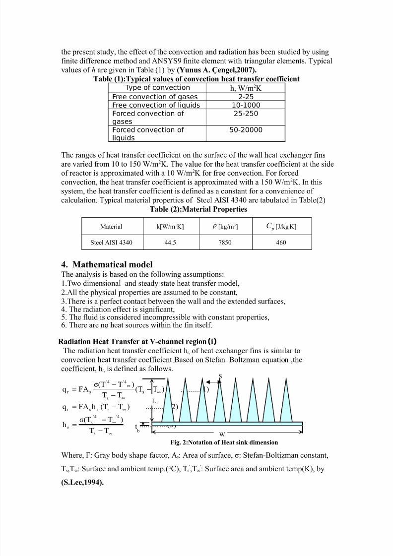
)i(Radiatio! Heat 6ra!sfer at ;-ca!!el regio!
The radiation heat transfer coefficient hr, of heat exchanger fins is similar toconvection heat transfer coefficient .[ased on %tefan [olt\man eVuation ,thecoefficient, hr, is defined as follows.
....(Y)..........TT
)TZ(Th
..()..........)T(ThQ#V
(1)..........)T(TTT
)TZ(TQ#V
s
sr
sr sr
s
s
sr
∞
∞
∞
∞∞
∞
−−
=
−=
−−−=
Where, Qj kray "ody shape factor, #sj #rea of surface, Zj %tefanR[olti\man constant,
Ts,Tj %urface and am"ient temp.(O), Ts,T
j %urface area and am"ient temp(!), "y
$.<ee,1&&:2.
S
Wt "
%
"ig. '7Notatio! of Heat si! dime!sio!
7/18/2019 Paper Ed7 16
http://slidepdf.com/reader/full/paper-ed7-16 4/12
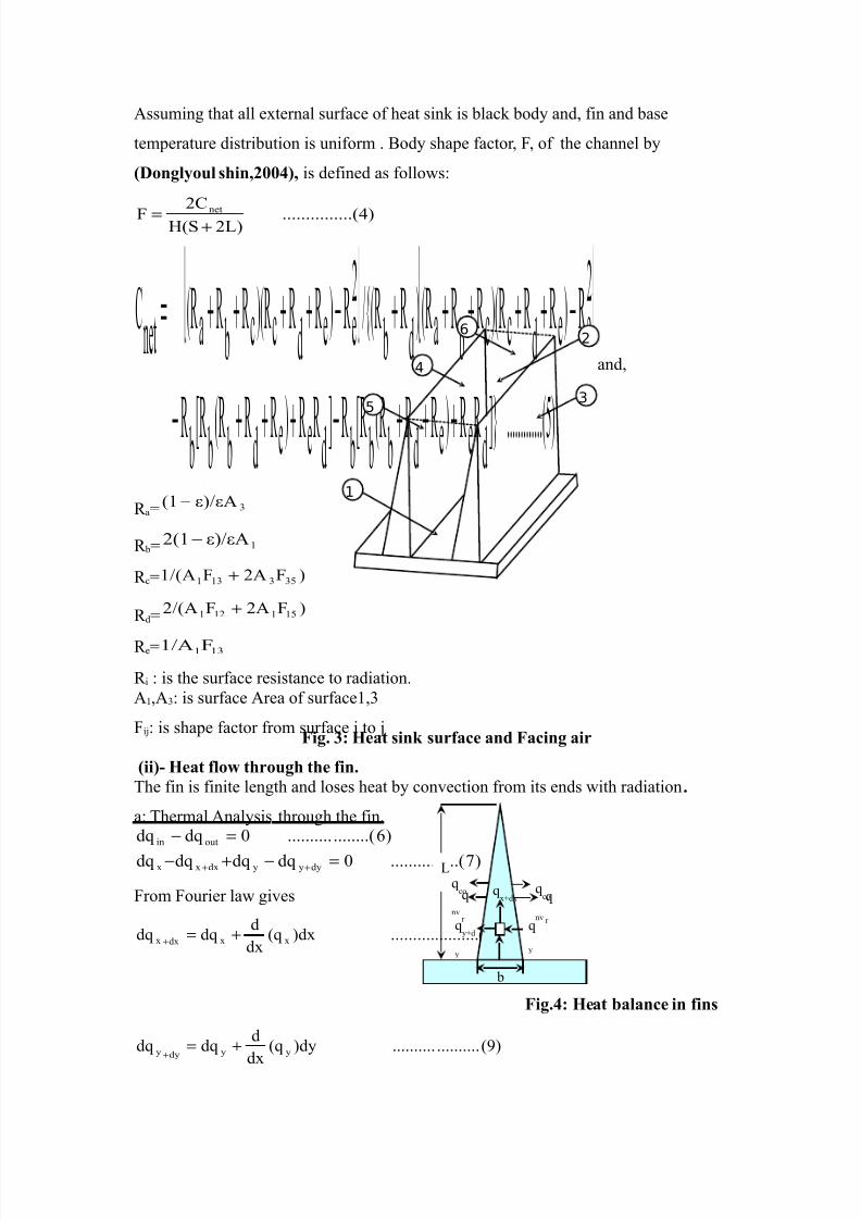
#ssuming that all external surface of heat sin is "lac "ody and, fin and "ase
temperature distri"ution is uniform . [ody shape factor, Q, of the channel "y
(o!glyoul si!,':2, is defined as followsj
.....()..........S)X(%
OQ net
+=
...(b)..........hmde)ed"("g"hde)ed"("g"
e)e
dc)(c
"a()
d
"/(
e)ed
c)(c"
a(netO
+++−+++−
−+++++−++++=
and,
a Y)/#(1−
" 1)/#(1−
c )Q#Q1/(# YbY1Y1 +
d)Q#Q/(# 1b111 +
e 1Y1Q1/#
i j is the surface resistance to radiation.#1,#Yj is surface #rea of surface1,Y
Qi_j is shape factor from surface i to _
ii2- Heat flow troug te fi!.
The fin is finite length and loses heat "y convection from its ends with radiation .
aj Thermal #nalysis through the fin.
)f.....(..........NdVdVdVdV
)........(..........NdVdV
dyyydxxx
outin
=−+−
=−
++
Qrom Qourier law gives
()....................)dx(Vdx
ddVdV xxdxx +=+
(')....................)dy(V
dx
ddVdV yydyy +=
+
"ig.:7 Heat bala!ce i! fi!s
V
x
V
y
"
S
Vco
nv
Vxqdx
Vyqd
y
V
r
Vco
nv
V
r
"
#
ƒ
„
…
"ig. 7 Heat si! surface a!d "aci!g air
7/18/2019 Paper Ed7 16
http://slidepdf.com/reader/full/paper-ed7-16 5/12
%u"stitution of ^V.(,and '), in ^V.(), gives
.....(1N)..........Ndydy
dT.#
dy
ddx
dx
dT.#
dx
d=
+
.....(11)..........N
dy
Td
dx
Td
=
+
"j Thermal #nalysis at the wall of the fin.
)1Y.....(..........NdVdVdVdVdVdV
)1........(..........NdVdV
radconvdyyydxxx
outin
≡−−−+−≡−
++
The convection heat transfer rate may "e expressed as
dVconv h .dx. (T RT) ..(1)
%u"stitution of ^V.(,,'and1), in ^V.(1Y), gives
( ) ( ) .....(1b)..........NTTZdxTTh.p..dy
dy
dT.#
dy
ddx
dx
dT.#
dx
d =−−−−
+
∞∞ s
FA
This eVuation can "e rearranged as
( ) ( ) .....(1)..........NTTmTT.mdy
Td
dx
Td
1
=−−−−
+
∞∞
where )1f......(..........,
1
kA
FAm
kA
hpm
S σ ==
iii2- "i!ite differe!ce formulatio!
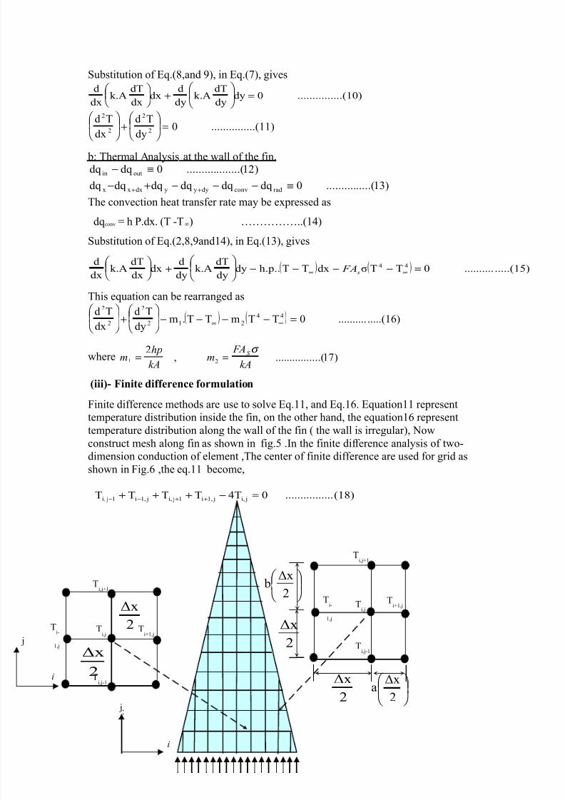
Qinite difference methods are use to solve ^V.11, and ^V.1. ^Vuation11 represent
temperature distri"ution inside the fin, on the other hand, the eVuation1 representtemperature distri"ution along the wall of the fin ( the wall is irregular), $owconstruct mesh along fin as shown in fig.b .`n the finite difference analysis of twoRdimension conduction of element ,The center of finite difference are used for grid asshown in Qig. ,the eV.11 "ecome,
(1c)................NTTTTT _i, _1,i1 _i, _1,i1 _i, =−+++ ++−−
j _
i
TiR
1,_
Ti,_
Tiq1,_
Ti,_q1
i
_
Ti,_q1
x "
TiR
1,_
Ti,_
Tiq1,_
x
x
xa
tx
x
Ti,_R1
Ti,_R1
7/18/2019 Paper Ed7 16
http://slidepdf.com/reader/full/paper-ed7-16 6/12
This eVuation used for all nodes in the fin respect the nodes near the wall analysis asirregular regions and used eVuation (1) "y Esli!ger a!d =u!g,1&4&2. Thetemperature distri"ution in irregular regions in the Qig. are used for all nodes near thewall and the dimension different for these nodes.
)1'.(..........
)(
1Y1
1
,1,
Y
,,1
h
h
T T
h
T T
T
!i !i !i !i
θ θ
θ θ
+
−−
−
=∂∂
−+
.(N)..........
)h(
1
h
TT
h
TT
y
T
1 _i, _i,
_i,1 _i,
+
−−
−
=∂∂
+−
$ow, su"stitutes ^V. 1',and ^V N in ^V.1 ,get
..(1)N.........)RT _i,
(T
mR)TR _i,
(T1
mR
_i,)T
u
u
1
Yu1u
1(
)
u
(u
u
1 _i,T
)Y
u1
(uY
u
_1,iT
)
u
(u
u
1 _i,T
)Y
u1
(u1u
_1,iRT
h
=∞∞
+−
+−
++
++
++
++
^Vuation 1 and 1 represent temperature distri"ution along fin after constructcomputer program to solve these eVuation and depend on "oundary condition also weneeded Newto!- Rafso! metod to solve ^V 1 "ecause the eVuation is nonRlinear and+aues Elimi!atio! method to solve ^V 1.
#2- 6e bou!dary co!ditio!s 7
Qrom the symmetrical of the system, the "oundary conditions are†a) [ase surface†
.........11bf.1f.1f.fx1.N1xY'.'x1.bbYxTWx
WandNy#t
....(..........Y1bf.'bfx1Y.fxY'.'x1.xT
WxNandNy#t
+−+−=≤≤=
+−+−=≤≤=
") Qins tipj
).........()TS
h(TSxdx
dT!.#.Sy#t ∞−=
=
−=
>. Results ;erificatio!7
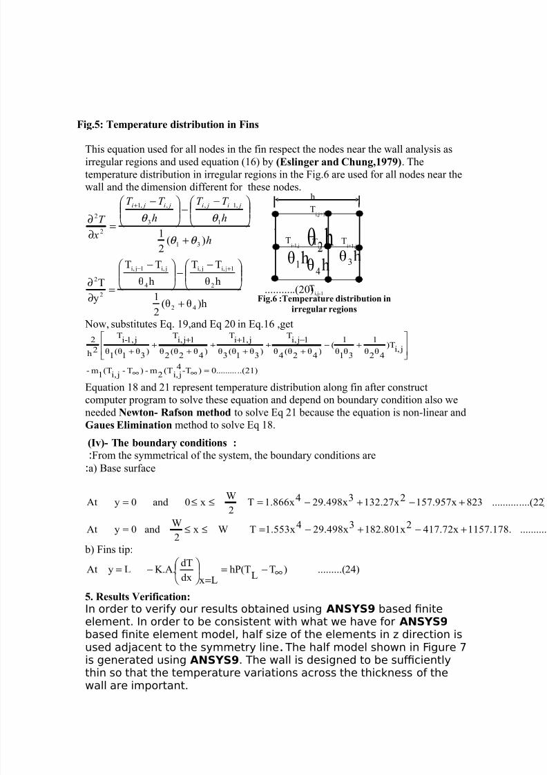
In order to verify our results obtained using ANSYS9 based niteelement. In order to be consistent with what we have for ANSYS9 based nite element model, half si‡e of the elements in ‡ direction isused adˆacent to the symmetry line. The half model shown in €igure ‰is generated using ANSYS9. The wall is designed to be suciently
thin so that the temperature variations across the thicŠness of thewall are important.
"ig.>7 6em)erature distributio! i! "i!s
Ti,_q1
TiR1,_ T
i,_T
iq1,_
hud
hu
hu1
h Y
"ig.? 76em)erature distributio! i!
irregular regio!s
h
Ti,_R1
7/18/2019 Paper Ed7 16
http://slidepdf.com/reader/full/paper-ed7-16 7/12
Fig.7:Meshing of the half moel
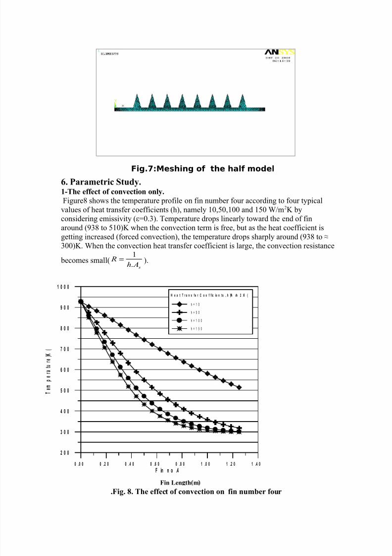
?. 9arametric $tudy.
1-6e effect of co!#ectio! o!ly. Qigure shows the temperature profile on fin num"er four according to four typicalvalues of heat transfer coefficients (h), namely 1N,bN,1NN and 1bN W/m! "yconsidering emissivity (N.Y). Temperature drops linearly toward the end of finaround ('Y to b1N)! when the convection term is free, "ut as the heat coefficient isgetting increased (forced convection), the temperature drops sharply around ('Y to YNN)!. When the convection heat transfer coefficient is large, the convection resistance
"ecomes small( s
Ah "
.
1= ).
"ig. @. 6e effect of co!#ectio! o! fi! !umber four.
0 .0 0 0 .2 0 0 .4 0 0 .6 0 0 . 0 ! .0 0 ! .2 0 ! .4 0
F in n o .4
2 0 0
" 0 0
4 0 0
# 0 0
6 0 0
$ 0 0
0 0
% 0 0
! 0 0 0
T
e
&
'
e
r a
t u
r e
( )
*
H e a t T r a n s f e r C o e f f ic ie n ts + h (, -& 2 .) *
h = 1 0
h = 5 0
h = 1 0 0
h = 1 5 0
"i! <e! t m
7/18/2019 Paper Ed7 16
http://slidepdf.com/reader/full/paper-ed7-16 8/12
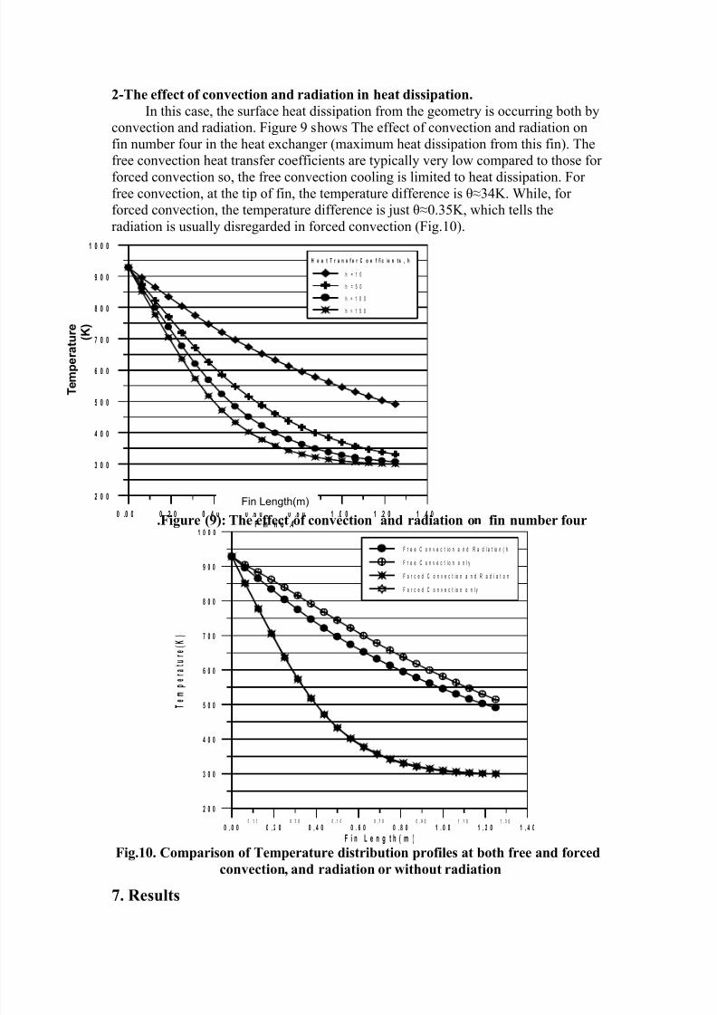
'-6e effect of co!#ectio! a!d radiatio! i! eat dissi)atio!.
`n this case, the surface heat dissipation from the geometry is occurring "oth "yconvection and radiation. Qigure ' shows The effect of convection and radiation onfin num"er four in the heat exchanger (maximum heat dissipation from this fin). Thefree convection heat transfer coefficients are typically very low compared to those for
forced convection so, the free convection cooling is limited to heat dissipation. Qorfree convection, at the tip of fin, the temperature difference is Y!. While, forforced convection, the temperature difference is _ust N.Yb!, which tells theradiation is usually disregarded in forced convection (Qig.1N).
"igure &27 6e effect of co!#ectio! a!d radiatio! o! fi! !umber four.
0 . 1 0 0 . 3 0 0 . 5 0 0 . 7 0 0 . 9 0 1 . 1 0 1 . 3 0
0 . 0 0 0 . 2 0 0 . 4 0 0 . 6 0 0 . 0 ! . 0 0 ! . 2 0 ! . 4 0
F i n e n g t h * & (
2 0 0
" 0 0
4 0 0
# 0 0
6 0 0
$ 0 0
0 0
% 0 0
! 0 0 0
T
e
&
'
e
r a
t u
r e
* )
(
F r e e C o n v e c t i o n a n d R a d i a t io n ( h
F r e e C o n v e c t i o n o n l y
F o r c e d C o n v e c t i o n a n d R a d i a t i o n
F o r c e d C o n v e c t i o n o n l y
"ig.1. =om)ariso! of 6em)erature distributio! )rofiles at bot free a!d forced
co!#ectio!, a!d radiatio! or witout radiatio!
4. Results
0 .0 0 0 .2 0 0 .4 0 0 .6 0 0 . 0 ! .0 0 ! .2 0 ! .4 0F in n o .4
2 0 0
" 0 0
4 0 0
# 0 0
6 0 0
$ 0 0
0 0
% 0 0
! 0 0 0
H e a t T r a n s f e r C o e f f ic ie n t s + h
h = 1 0
h = 5 0
h = 1 0 0
h = 1 5 0
Fin Length(m)
T e & ' e r a t u r e * ) (
7/18/2019 Paper Ed7 16
http://slidepdf.com/reader/full/paper-ed7-16 9/12
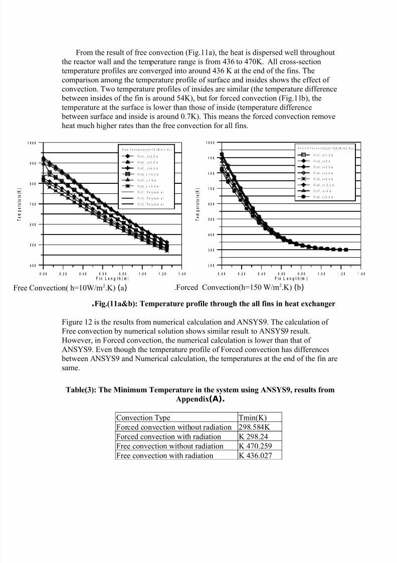
Qrom the result of free convection (Qig.11a), the heat is dispersed well throughoutthe reactor wall and the temperature range is from Y to N!. #ll crossRsectiontemperature profiles are converged into around Y ! at the end of the fins. Thecomparison among the temperature profile of surface and insides shows the effect ofconvection. Two temperature profiles of insides are similar (the temperature difference
"etween insides of the fin is around b!), "ut for forced convection (Qig.11"), thetemperature at the surface is lower than those of inside (temperature difference
"etween surface and inside is around N.!). This means the forced convection removeheat much higher rates than the free convection for all fins.
"ig.11ab27 6em)erature )rofile troug te all fi!s i! eat exca!ger.
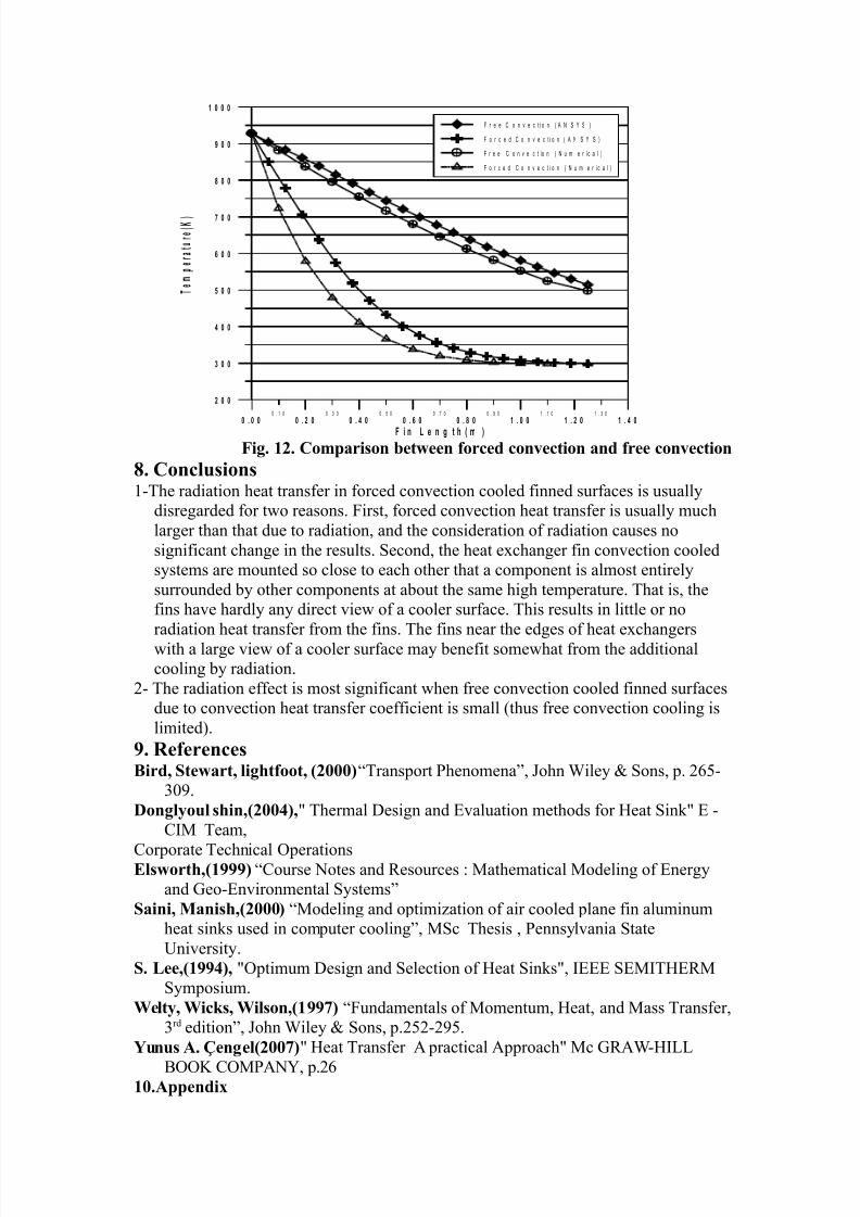
Qigure 1 is the results from numerical calculation and #$%&%'. The calculation ofQree convection "y numerical solution shows similar result to #$%&%' result.Xowever, in Qorced convection, the numerical calculation is lower than that of#$%&%'. ^ven though the temperature profile of Qorced convection has differences
"etween #$%&%' and $umerical calculation, the temperatures at the end of the fin aresame.
6able27 6e 8i!imum 6em)erature i! te system usi!g AN$%$&, results fromA))e!dix(A).
Oonvection Type Tmin(!)Qorced convection without radiation '.b! Qorced convection with radiation '.! Qree convection without radiation N.b'! Qree convection with radiation Y.N!
0 . 0 0 0 . 2 0 0 . 4 0 0 . 6 0 0 . 0 ! . 0 0 ! . 2 0 ! . 4 0
F i n e n g t h * & (
4 0 0
# 0 0
6 0 0
$ 0 0
0 0
% 0 0
! 0 0 0
T
e
&
'
e
r a
t u r e
* )
(
F r e e C o n v e c t i o n ( h = 1 0 ( W m ! . " ) )
F i n 3 # $ = ! . % m
F i n & # $ = 3 . ' m
F i n 5 # $ = & . & m
F i n ' # $ = 5 . ! m
F i n 7 # $ = ' m
F i n % # $ = ' . % m
F i t 1 o l y n o m i a l
F i t ! o l y n o m i a l
F i t 3 o l y n o m i a l
0 . 0 0 0 . 2 0 0 . 4 0 0 . 6 0 0 . 0 ! . 0 0 ! . 2 0 ! . 4 0
F i n e n g t h * & (
2 0 0
" 0 0
4 0 0
# 0 0
6 0 0
$ 0 0
0 0
% 0 0
! 0 0 0
T
e
&
'
e
r a
t u r
e
* )
(
F o r c e d C o n v e c t i o n ( h = 1 5 0 ( W m ! . " ) )
F i n 1 # $ = 1 . ! m
F i n ! # $ = ! m
F i n 3 # $ = ! . % m
F i n & # $ = 3 . ' m
F i n 5 # $ = & . & m
F i n ' # $ = 5 . ! m
F i n 7 # $ = ' m
F i n % # $ = ' . % m
aqQree Oonvection( h1NW/m.!) "qQorced Oonvection(h1bN W/m.!).
7/18/2019 Paper Ed7 16
http://slidepdf.com/reader/full/paper-ed7-16 10/12
0 . 1 0 0 . 3 0 0 . 5 0 0 . 7 0 0 . 9 0 1 . 1 0 1 . 3 0
0 . 0 0 0 . 2 0 0 . 4 0 0 . 6 0 0 . 0 ! . 0 0 ! . 2 0 ! . 4 0
F i n e n g t h * & (
2 0 0
" 0 0
4 0 0
# 0 0
6 0 0
$ 0 0
0 0
% 0 0
! 0 0 0
T
e
&
'
e
r a
t u
r e
* )
(
F r e e C o n v e c t i o n ( * + , - , )
F o r c e d C o n v e c t i o n ( * + , - , )
F r e e C o n v e c t io n ( + m e r i c a l )
F o r c e d C o n v e c t i o n ( + m e r i c a l )
"ig. 1'. =om)ariso! betwee! forced co!#ectio! a!d free co!#ectio!
@. =o!clusio!s1RThe radiation heat transfer in forced convection cooled finned surfaces is usually
disregarded for two reasons. Qirst, forced convection heat transfer is usually muchlarger than that due to radiation, and the consideration of radiation causes nosignificant change in the results. %econd, the heat exchanger fin convection cooledsystems are mounted so close to each other that a component is almost entirelysurrounded "y other components at a"out the same high temperature. That is, thefins have hardly any direct view of a cooler surface. This results in little or no
radiation heat transfer from the fins. The fins near the edges of heat exchangerswith a large view of a cooler surface may "enefit somewhat from the additionalcooling "y radiation.
R The radiation effect is most significant when free convection cooled finned surfacesdue to convection heat transfer coefficient is small (thus free convection cooling islimited).
&. Refere!ces0ird, $tewart, ligtfoot, '2Transport henomena, Pohn Wiley %ons, p. bR
YN'.(o!glyoul si!,':2,z Thermal Design and ^valuation methods for Xeat %inz ^ R
O`U Team,
Oorporate Technical perationsElswort,1&&&2 Oourse $otes and esources j Uathematical Uodeling of ^nergy
and keoR^nvironmental %ystems$ai!i, 8a!is,'2 Uodeling and optimi\ation of air cooled plane fin aluminum
heat sins used in computer cooling, U%c Thesis , ennsylvania %tate{niversity.
$. <ee,1&&:2, zptimum Design and %election of Xeat %insz, `^^^ %^U`TX^U%ymposium.
3elty, 3ics, 3ilso!,1&&42 Qundamentals of Uomentum, Xeat, and Uass Transfer,Yrd edition, Pohn Wiley %ons, p.bR'b.
%u!us A. 5e!gel'42 Xeat Transfer # practical #pproachz Uc k#WRX`SS
[! OU#$&, p.1.A))e!dix
7/18/2019 Paper Ed7 16
http://slidepdf.com/reader/full/paper-ed7-16 11/12
a2B13/m'.K b2B1 3/m'.K
c2B> 3/m'.K d2B1> 3/m'.K
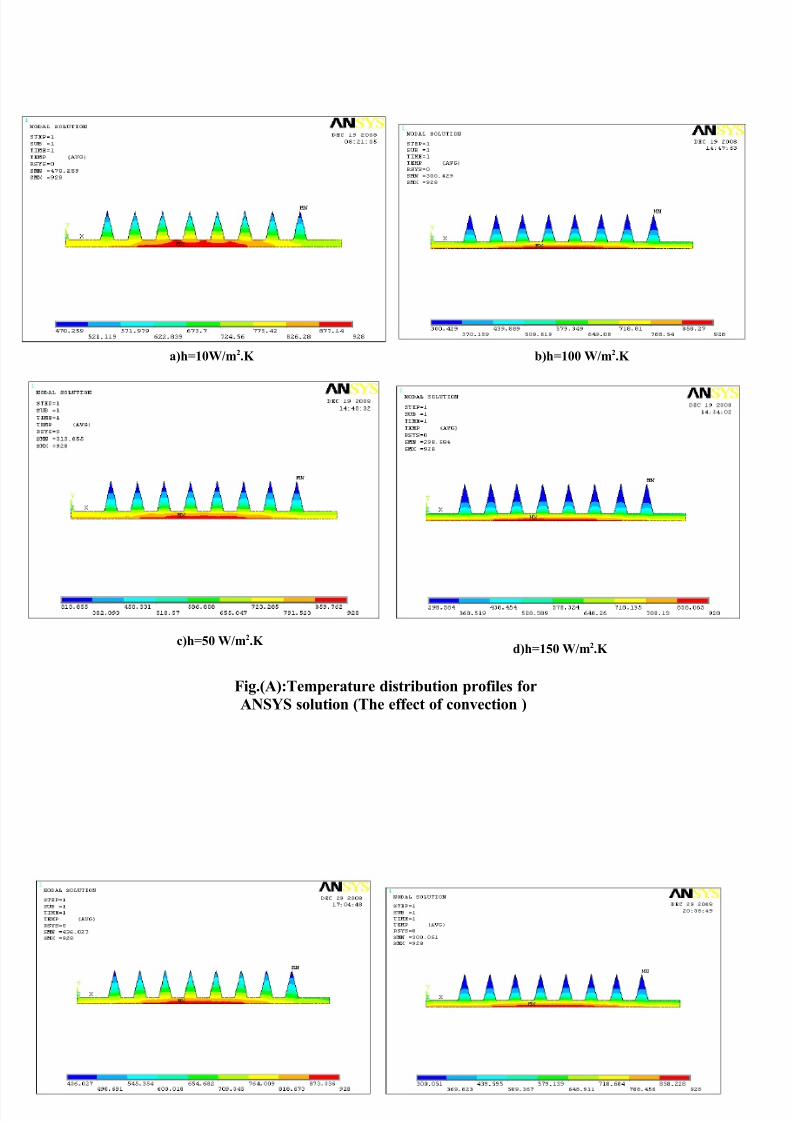
"ig.A276em)erature distributio! )rofiles for
AN$%$ solutio! 6e effect of co!#ectio! 2
7/18/2019 Paper Ed7 16
http://slidepdf.com/reader/full/paper-ed7-16 12/12
1
1
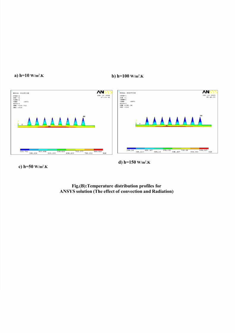
"ig.0276em)erature distributio! )rofiles for
AN$%$ solutio! 6e effect of co!#ectio! a!d Radiatio!2
a2 B1 3/m'.K b2 B1 3/m'.K
d2 B1> 3/m'.K
c2 B> 3/m'.K