Embed Size (px)
Citation preview

PaPer Presentation20th February, 2009
Shareef
PH08D022

Direct-Write Piezoelectric Polymeric Nanogenerator with High Energy Conversion Efficiency
Chieh Chang, Van H. Tran, Junbo Wang, Yiin-Kuen Fuh and Liwei Lin
Berkeley Sensor and Actuator Center, University of California, USADepartment of Medical Engineering, TUM, Germany
State Key Laboratory of Transducer Technology , Institute of Electronics, China
2010, 10 (2), pp 726–731

Present work
•Large scale and small scale power production from mechanical energy
•Nanogenerator convert mechanical energy into electricity on small scale
•Piezoelectric PVDF nanofiber as nanogenerator
•PVDF has good piezoelectrical and mechanical properties with chemical stability and weathering characteresics
•Energy conversion efficiency of PVDF nanofiber is more as compared to its film
•Potential application as sensors and actuators

PVDF solution preparation
The PVDF solutions with DMF/acetone solvents were prepared using the following steps:a. 1.8 g PVDF powder was dispersed in 4 g acetone for 30 minutes using a magnetic stirrer.b. The complete PVDF solution was prepared by mixing 6 g DMF with the PVDF/acetone solution. 0.3 g Zonyl®UR was simultaneously added to the mixture. The mixture was then stirred for a minimum of one hour to reach sufficient homogeneity.
PVDF nanofiber synthesis
•Near Field Electrospinning(NFES) is used to produce nanofibers
•The high field(>107V/m) and stretching force in the process align dipoles in the nanofiber crystal and transform non polar α phase into polar βphase, makes the fiber polar
•Diameter range from 500 nm to 6.5 µm and length 100- 600 µm
•The fibers are deposited in between two metallic electrodes over a plastic substrate
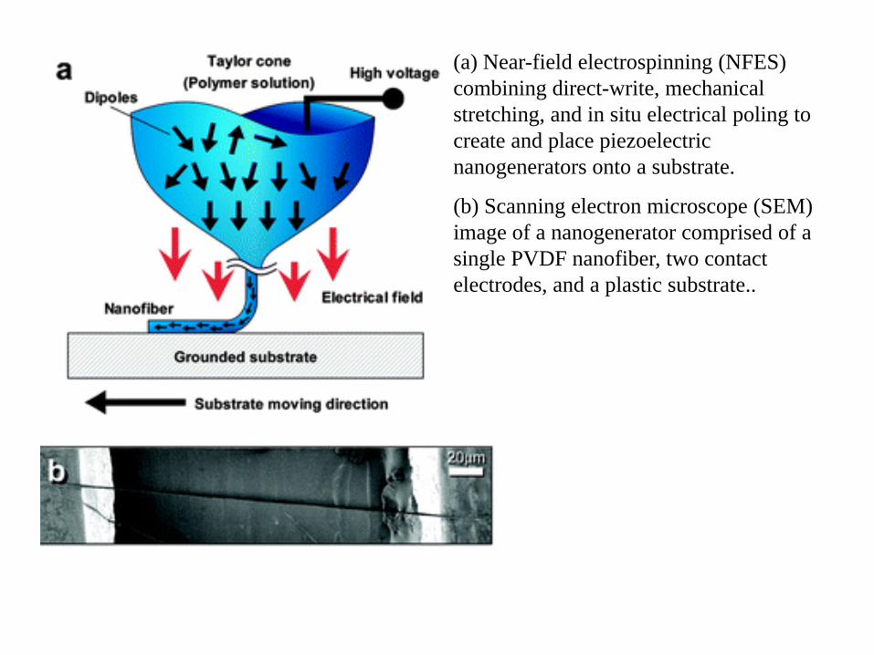
(a) Near-field electrospinning (NFES) combining direct-write, mechanical stretching, and in situ electrical poling to create and place piezoelectric nanogenerators onto a substrate.
(b) Scanning electron microscope (SEM) image of a nanogenerator comprised of a single PVDF nanofiber, two contact electrodes, and a plastic substrate..
Piezoelectric action
•By applying an axial stress on the substrate, a piezoelectric potential is developed and the repeated application of stress, voltage and current can be recorded
•Randomly distributed nanofibers of PVDF by conventional electrospinning does not give any measurable outputs since they do not have controlled polarity
•Non piezoelectric polymers like PEO does not give electrical outputs
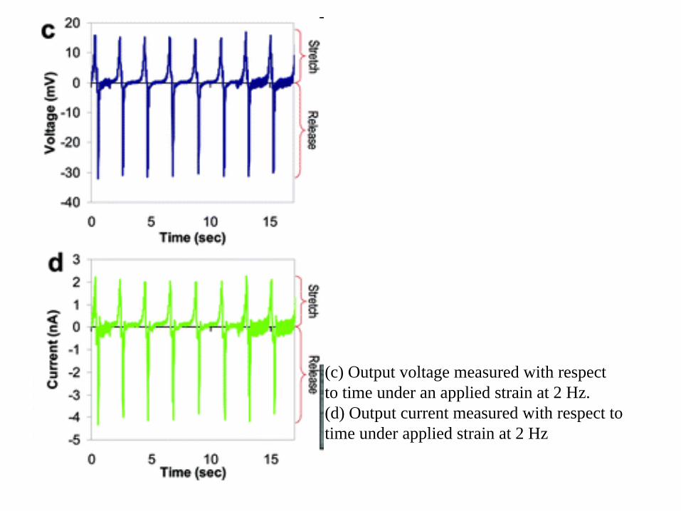
(c) Output voltage measured with respectto time under an applied strain at 2 Hz. (d) Output current measured with respect to time under applied strain at 2 Hz

(a) Voltage output of a single PVDF nanofiber subject to continuous stretch and release. (b)Voltage output of a single PEO nanofiber subject to continuous stretch and release
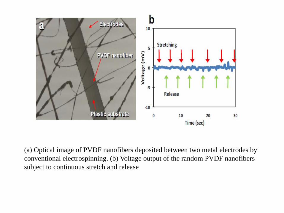
(a) Optical image of PVDF nanofibers deposited between two metal electrodes by conventional electrospinning. (b) Voltage output of the random PVDF nanofibers subject to continuous stretch and release
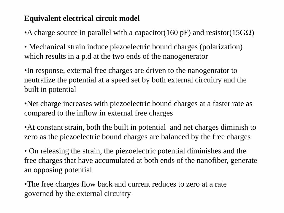
Equivalent electrical circuit model
•A charge source in parallel with a capacitor(160 pF) and resistor(15GΩ)
• Mechanical strain induce piezoelectric bound charges (polarization) which results in a p.d at the two ends of the nanogenerator
•In response, external free charges are driven to the nanogenrator to neutralize the potential at a speed set by both external circuitry and the built in potential
•Net charge increases with piezoelectric bound charges at a faster rate as compared to the inflow in external free charges
•At constant strain, both the built in potential and net charges diminish to zero as the piezoelectric bound charges are balanced by the free charges
• On releasing the strain, the piezoelectric potential diminishes and the free charges that have accumulated at both ends of the nanofiber, generate an opposing potential
•The free charges flow back and current reduces to zero at a rate governed by the external circuitry
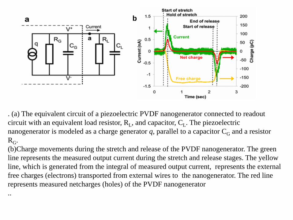
. (a) The equivalent circuit of a piezoelectric PVDF nanogenerator connected to readout circuit with an equivalent load resistor, RL, and capacitor, CL. The piezoelectric nanogenerator is modeled as a charge generator q, parallel to a capacitor CG and a resistor RG. (b)Charge movements during the stretch and release of the PVDF nanogenerator. The green line represents the measured output current during the stretch and release stages. The yellow line, which is generated from the integral of measured output current, represents the external free charges (electrons) transported from external wires to the nanogenerator. The red line represents measured netcharges (holes) of the PVDF nanogenerator..
b

Impedance measurement (blue dots) and data-fitted analytical model (red solid line) of the PVDF nanogenerator. Output impedance reduces withfrequency. As the cycling frequency increases from 2 to 4 Hz, the impedancedrops from 900 to 300 MΩ
Impedance measurement
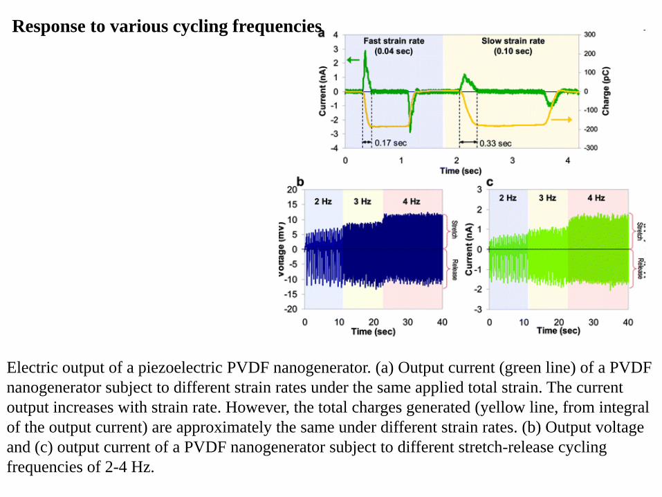
Electric output of a piezoelectric PVDF nanogenerator. (a) Output current (green line) of a PVDF nanogenerator subject to different strain rates under the same applied total strain. The current output increases with strain rate. However, the total charges generated (yellow line, from integral of the output current) are approximately the same under different strain rates. (b) Output voltage and (c) output current of a PVDF nanogenerator subject to different stretch-release cycling frequencies of 2-4 Hz.
Response to various cycling frequencies

Output voltages of (a) nanogenerator #1 and (b) nanogenerator #2 subject to continuous stretch and release. (c) Output voltages constructively add when two nanogenerators are in serial connection. Output currents of (d) nanogenerator #1 and (e) nanogenerator #2 subject to continuous stretch and release. (f) Output currents constructively add when two nanogenerators are in parallel connection. All data are measured when the two nanogenerators are operated in the same strain, strain rate, and frequency
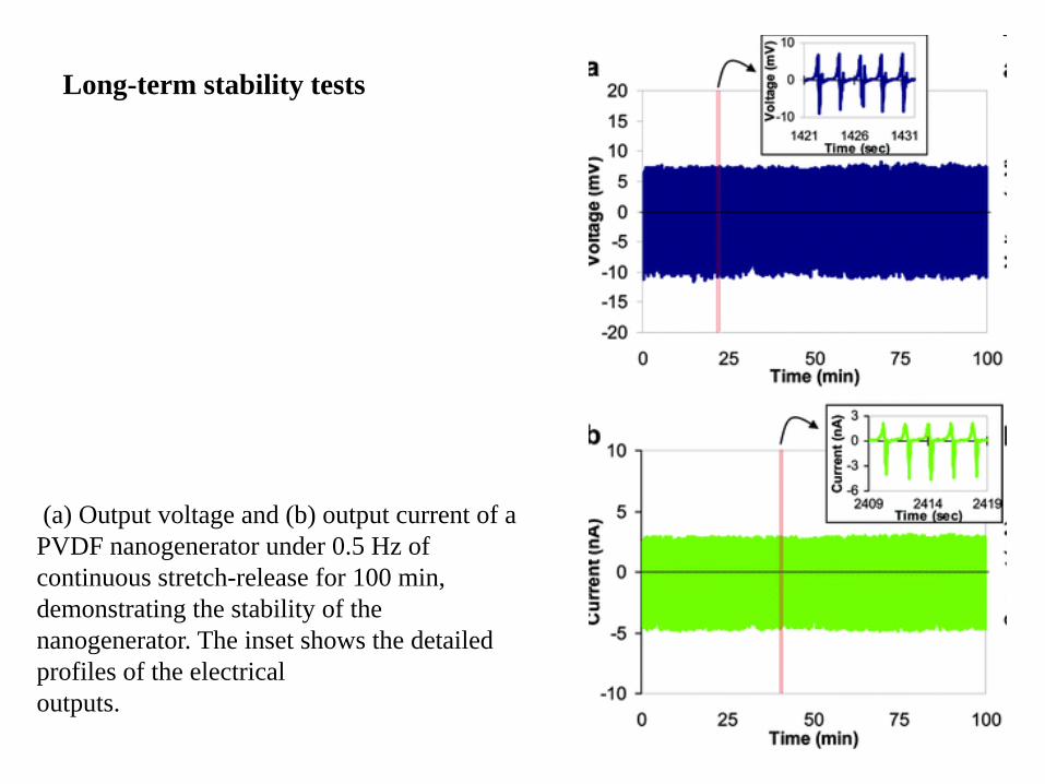
(a) Output voltage and (b) output current of a PVDF nanogenerator under 0.5 Hz of continuous stretch-release for 100 min, demonstrating the stability of the nanogenerator. The inset shows the detailed profiles of the electricaloutputs.
Long-term stability tests
Energy conversion efficiency
•Much higher than PVDF thin films
•It is 12.5% for nanofiber and 1.3% for thin film
•Thinner fibers have higher energy conversion efficiency
•The nanofibers have fewer defects than thin film due to higher degree of crystallinity and chain orientation
•Size dependent piezoelectricity caused by strain gradients that locally break inversion symmetry and induce polarization
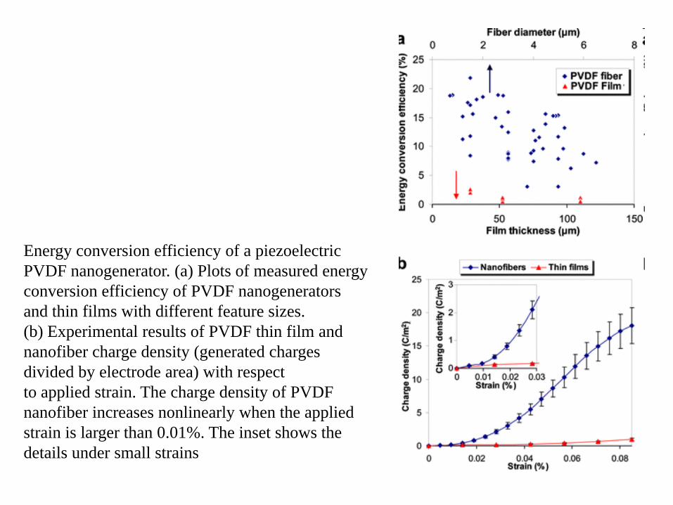
Energy conversion efficiency of a piezoelectric PVDF nanogenerator. (a) Plots of measured energy conversion efficiency of PVDF nanogenerators and thin films with different feature sizes.(b) Experimental results of PVDF thin film and nanofiber charge density (generated charges divided by electrode area) with respectto applied strain. The charge density of PVDF nanofiber increases nonlinearly when the applied strain is larger than 0.01%. The inset shows the details under small strains
Summary
•PVDF nanogenerators are directly written onto flexible plastic substrate using NFES
•The piezoelectric responses of single nanofibers were measured and multiple nanofibers were arranged to enhance the electrical outputs
•It has high energy conversion efficiency, manufacturability, long term stability and capability of integration with other micro/nano fabrication processes
•Nanogenerator could be the basis for an integrated power source in nanodevices and wireless sensors or new self powered textile by direct writing nanofibers onto a large area cloth to boost the total power output for portable electronics