Embed Size (px)
Citation preview
TRAPPED TOOLING FOR SELECTIVELY STIFFENED LIGHTWEIGHT COMPOSITE STRUCTURES
Mathias Hecht, Robert Harshberger, and Finley MillerRubbercraft
3701 Conant St.Long Beach, CA 90808
Ed Wen, James SniderAurora Flight Sciences9950 Wakeman Drive Manassas, VA 20110
ABSTRACT Advanced composite structures increasingly take advantage of the unique anisotropic capabilities of the composite material to minimize weight and cost. One of the successful techniques is to selectively stiffen structures using hollow elements that are integrated into the surface of the composites. These stiffened structures can be formed in- and out-of-autoclave using both inner mold line and outer mold line lay-up tooling. Because the structural features of the advanced composites are hollow, the tooling is trapped and needs to be removed after curing. Different technologies to manufacture and remove such tooling are being assessed. A comparison of the advanced stiffened structures to traditional honeycomb containing composites is also discussed. A case study with elastomeric tooling is presented.
1. INTRODUCTION
The continued evolution of computer modeling tools together with the growing experience in the manufacturing of fiber reinforced composites allows the design and construction of increasingly complex and lightweight integrated structures. These structures can take advantage of the unique anisotropic properties of the composite materials to optimize weight and reduce cost. Instead of producing separate parts that are bonded or fastened together, or are stiffened by adding ply thickness, more advanced structures can be built that do not have to be assembled, bonded, or fastened, and can have stiffening elements built-in. However, manufacturing more complex integrated structures complicates the tooling needed to form these parts. The tradeoff is between the initial tooling cost and the weight and recurring cost to produce the final part.
Copyright 2016 by Rubbercraft. Published by Society for theAdvancement of Material and Process Engineering with permission.
Optimized structural designs often result in part features for which traditional hard tooling could no longer be removed once the part is cured. Often, a lightweight material such as honeycomb, foam, or thin liners is enclosed to support the hollow feature and remains in the part throughout the service life. However, such materials can take up moisture, complicate the manufacturing, and are often not the ideal solution for the optimum weight to cost combination for the particular application, as these fillers are typically inferior in weight to mechanical performance ratio compared to the fiber reinforced composites. Instead, specifically designed tooling for trapped applications can be used that can be removed after the part is cured. Therefore, trapped tooling plays an important role in the design process.
Similar to lay-up tooling, collapsible hard tools made from materials like Invar, steel, composite, or plastics can be used [1,2]. The application of such tools is limited to easily accessible cavities. These tools are inherently complex, costly, and can leave interior seams or resin ridges. At the same time, they offer close control of tolerances similar to hard lay-up tools made of the same materials. An advantage is also that Invar, steel, or plastic tools can be formed by machining, removing the need for a dedicated tool to produce the trapped tool.
Eutectic salts and low melting points alloys have historically also been used for trapped tooling [3,4]. These materials are of high density, single use, and need to be formed in dedicated molds.
Elastomeric compounds [5, 6] are also used for trapped tooling. The tools are formed in molds or by extrusion. The high elongation capability makes it possible to pull the trapped tools out after curing. An important advantage is that elastomeric tooling can be internally inflated in an out of autoclave application or vented to the autoclave to apply internal pressure to the structure during the cure cycle. The relatively high CTE of the elastomeric materials can provide a benefit in consolidation, but can also present design challenges. The CTE as well as the inherent softness of the lay-up surface, often necessitates less stringent tolerance requirements if the elastomeric tooling is being used to define the part geometry. However, if an inflatable elastomeric tool is being used to press the composite material into a rigid form, very tight tolerances are achievable. An advantage of the flexibility is that the same tools with the same cross-section can be laid-up in different ways, for instance in similar cavities with different ply-drops, which reduces the initial tooling cost to form these tools.
Water soluble materials containing ceramic micro-spheres or sand with a binder such as polyvinyl alcohol are also been used [7, 6, 9, 10]. These tools can be washed away and need the least access in the cured composite parts for removal. However, the materials are incompatible with most resin systems and need interface layers made from inert materials such as fluorinated polymers that need to be removed. Some of the more advanced materials can be made by additive manufacturing [11]. They are inherently single use tools, which either need to be formed in a mold, machined, or additively manufactured, which is typically only economical for prototype to small series production [11].
Engineered polymer composites [5, 6] can provide a hard lay-up surface, while being flexible and removable at elevated temperatures above the glass transition temperature (Tg) of most epoxy based resins. The tools are pulled-out at elevated temperature in the soft state, re-formed in a separate tool, and reused. Limitations include the stiffness at low temperatures that prevents the application of pressure, the requirement for a heated re-forming tool, and the need to have

dedicated trapped tools for separate shapes, due to the inflexibility of the tools at room temperature.
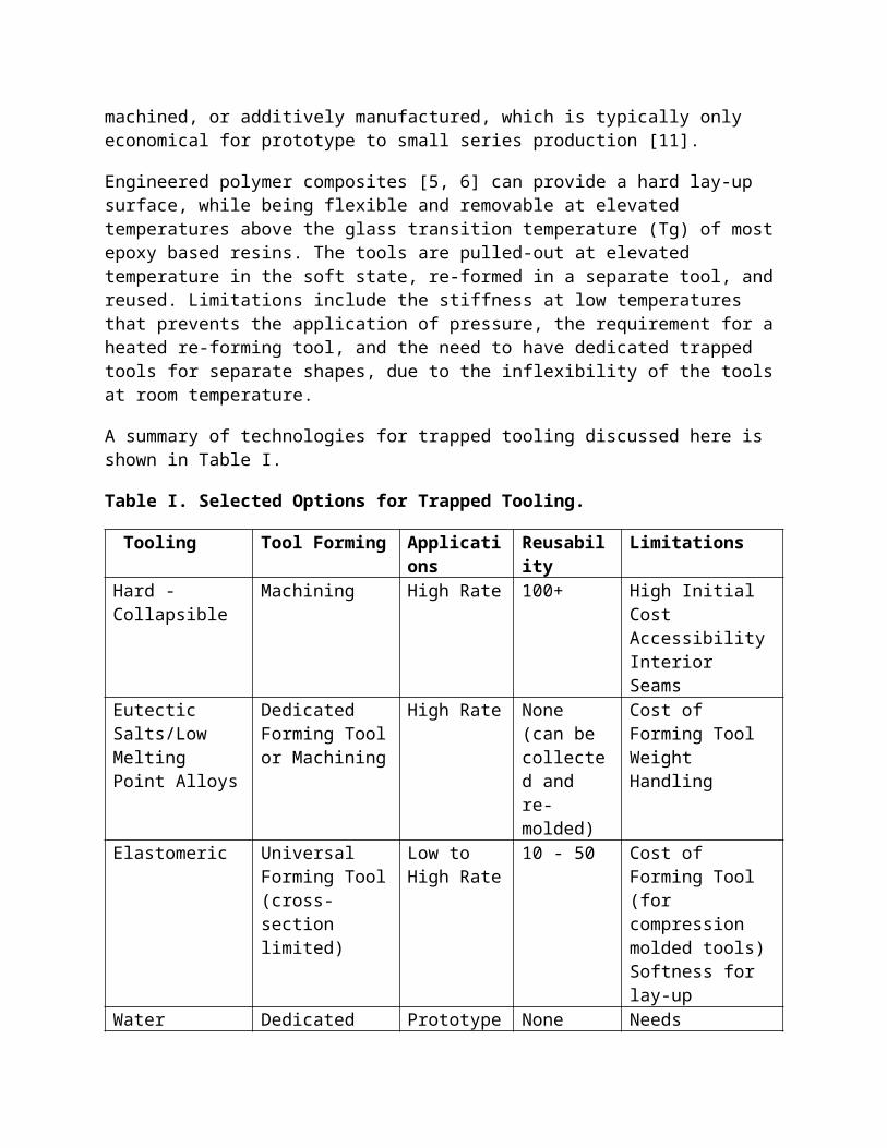
A summary of technologies for trapped tooling discussed here is shown in Table I.
Table I. Selected Options for Trapped Tooling.
Tooling Tool Forming Applications Reusability LimitationsHard - Collapsible Machining High Rate 100+ High Initial Cost
AccessibilityInterior Seams
Eutectic Salts/Low Melting Point Alloys
Dedicated Forming Tool or Machining
High Rate None (can be collected and re-molded)
Cost of Forming ToolWeightHandling
Elastomeric Universal Forming Tool (cross-section limited)
Low to High Rate
10 - 50 Cost of Forming Tool (for compression molded tools)Softness for lay-up
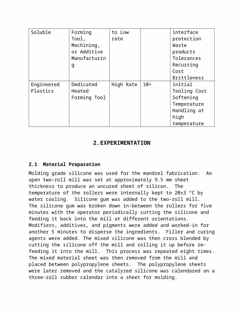
Water Soluble Dedicated Forming Tool, Machining, or Additive Manufacturing
Prototype to Low rate
None Needs interface protectionWaste productsTolerancesRecurring CostBrittleness
Engineered Plastics
Dedicated Heated Forming Tool
High Rate 10+ Initial Tooling CostSoftening TemperatureHandling at high temperature
2. EXPERIMENTATION
2.1 Material Preparation
Molding grade silicone was used for the mandrel fabrication. An open two-roll mill was set at approximately 9.5 mm sheet thickness to produce an uncured sheet of silicon. The temperature of the rollers were internally kept to 20±3 °C by water cooling. Silicone gum was added to the two-roll mill. The silicone gum was broken down in-between the rollers for five minutes with the operator periodically cutting the silicone and feeding it back into the mill at different orientations. Modifiers, additives, and pigments were added and worked-in for another 5 minutes to disperse the ingredients. Filler and curing agents were added. The mixed silicone was then cross blended by cutting the silicone off the mill and rolling it up before re-feeding it into the mill. This process was repeated eight times. The mixed material sheet was then removed
from the mill and placed between polypropylene sheets. The polypropylene sheets were later removed and the catalyzed silicone was calendared on a three-roll rubber calendar into a sheet for molding.
2.2 Forming of the Elastomeric Tooling
The calendared silicone was cut into sheets for compression molding. Protective foils and silicone sheets were stacked and molded in a compression mold at 170±5 °C.
2.3 Characterization of the Elastomeric ToolingTest coupons of the mandrel material were prepared by curing the mixed silicone compound in a heated press. The density was measured according to ASTM D297. Durometer was determined per ASTM D2240. Tensile and elongation properties were evaluated per ASTM D412 and specific gravity per ASTM D297. The compression set was measured per ASTM D395.
2.4 Preparation of the Composite StructurePlain weave BMI prepreg with a per - ply thickness of 0.2 mm was used. The skin plies were laid-up on a flat plate and debulked under vacuum at room temperature after every third ply. The 0 degree direction was parallel to the orientation of the mandrels. The skin layup consisted of 12 plies with alternating 0/90 and ±45 orientations.
Over-wrap plies to form the hats were wrapped around the mandrels and debulked. The ply orientation of the four overwrap plies was ±45 and 0/90. The fillets were formed by rolling strips of prepreg and pressing it under vacuum between a radii on both sides. The formed filet was then positioned on the skin under the edges of the wrapped mandrel. Four hat plies were added. After lamination, these plies were also debulked with vacuum. Peel ply was applied over the laminate. A non-porous fluorinated polymer film was placed over the laminate and sealed to the cure plate with sealant tape. A non-woven nylon breather was applied and the layup was vacuum bagged with nylon film.
The part was then placed in an autoclave under vacuum. The part was first heated to 135 °C at a ramp rate of approximately 3 °C per minute. After a 30 minute hold at 135 °C, full autoclave pressure of 620 kPa was applied. The part was then heated at approximately 3 °C per minute to 190 °C, where it was held for 3 hours. Subsequently, the part was cooled at a rate of approximately 3°C per minute. The autoclave was then opened and the part was removed and de-tooled.
3. RESULTS
Elastomeric tooling has been selected for the case study, due to its range of applications from semi-rigid lay-up tooling to soft inflatable bladders. Mandrels have been fabricated. The term mandrel implies the primary function to support lay-up. It is typically a solid elastomeric structure that may contain reinforcements, fillers, and/or stiffeners. The term bladder would be
used for tooling with the primary function of pressure transfer. In practice, the general trend is to employ bladders to transfer pressure to the inside of stiffeners in Inner Mold Line (IML) tooled applications (where the outside of the stiffener is supported by a rigid tool), and mandrels to provide support to the inside of stiffeners in Outer Mold Line (OML) tooled applications (where the outside of the stiffener is not rigidly supported (vacuum bag or autoclave bag side). For the stiffener itself, both mandrels and bladders support the stiffener in an IML approach as they are placed inside the stiffener. However, here the larger - stiffened part is considered for the OML or IML designation.
For this study, solid mandrels have been fabricated for providing stiffener internal IML support to a stiffened skin on an OML tool. Hollow hat-stiffened composite structures have been produced using these mandrels.
3.1 Selection and Characterization of the Elastomeric Tooling Material
Selecting a material system for a particular application can be accomplished by a combination of design, experimentation at the prototype scale, and manufacturing trials in a production environment. The primary reason for performing manufacturing trials with the actual materials, processes, and equipment is to optimize the longevity of the elastomeric tooling, and its cost effectiveness (cost per cure). A secondary reason for performing the manufacturing trials is to build experience in working with this tooling prior to production implementation.
Each composite application will be unique and requires a customized elastomeric tooling solution. The design and material selection criteria for the elastomeric tooling will depend on the specific requirements of the composite structure being supported. A wide range of materials and geometric configurations are available. The composite structure, the elastomeric tooling system, and the non-elastomeric tooling system will each have requirements that must be understood and addressed in order to optimize the elastomeric tooling solution provided for maximum productivity.
For this case study a silicone material with a protective interface layer made of a 0.1 mm thick fluoropolymer film has been selected. The purpose of the protective film is to form an inert barrier layer to the epoxy or other resin used in the composite and to facilitate the removal of the mandrel. The barrier layer is permanently attached to the silicone body of the tool.
Table II shows a list of properties measured for the silicone material used to form the mandrels.
Table II. Properties of the Elastomeric Tooling Material
Density [g/cm3] Durometer (Shore A)
Tensile Strength
[kPa]
Elongation at failure
[%]
Compression Set @70 hrs @177°C
Test Method
ASTM D297 ASTM D2240 ASTM D412
ASTM D412 ASTM D395, Method B
Result 1.27 60 9900 380 8%
The precision of the height requirement drives the level of shrinkage and/or compression set resistance required. A high temperature, low compression set, compound would be selected for tight tolerance requirements. Because the mandrels are typically molded in a straight shape, there are durometer related limits in curvature of the interior composite features. If more curvature is required, a lower durometer, and/or softer barrier film can be used or the film can be eliminated.
3.2 Designing and Fabricating the Elastomeric ToolsThe goal of the trapped elastomeric design is to provide an easily extractable tool with maximum reusability that produces the interior features of the composites to the desired dimensions and tolerances.
The cross-section of the mandrels increases with increasing temperature due to the CTE of the material. Experience has shown that the mandrel cross sections and radii grow by approximately 5% from room temperature to a composite cure temperature of 180 °C. Therefore, the mandrels are designed to size at cure temperature instead of room temperature. In addition, the mandrels are compression molded at elevated temperature and the temperature profile and mold dimensions need to be selected to match the cross-linking temperature of the elastomer to the size of the mandrel at this temperature. The cross-section used is illustrated in Figure 1.
Figure 1. Mandrel Cross-Section. R denotes radius, H height, and W width.
The elastomeric material will continue to cross-link at elevated temperature, which results in shrinkage of the mandrels. The length and cross section dimensions shrink equally as a percentage of this dimension unless isotropic reinforcements are used that direct this shrinkage. Since no such reinforcements are used here, the majority of the shrinkage will occur in length, because the mandrel is significantly longer than wide or high. A heat treatment also referred to as post-curing can be used to minimize this shrinkage during composite manufacturing, which can
increase the reusability of the tooling. This post-cure shrinkage needs to be accounted for in the design. Tighter tolerance requirements can be accommodated if the tooling is post-cured.
Corner radii offsets are also applied to counter localized radii over-compression. Based on the composite and mandrel material system geometric these offsets are applied in the design.
Because of the CTE of the mandrel material system, careful cross section sizing must be performed. The starting point for these considerations is the targeted finished composite hat inner cross-section. The intermediate design point is the predicted mandrel size at room temperature. The thermal expansion of the mandrel and any know interactions in terms of length and width restraint, thermal lag, etc. are the final design elements to calculate the required offsets.
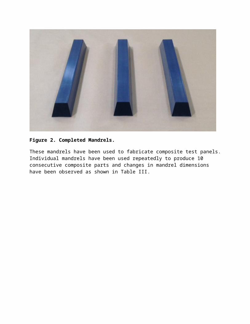
The mandrel length is treated differently in the design process than the cross section. In general, the delivered length is net to the design requirements and incorporates excess to allow for some shrinkage due to the repeated use of the tool. This means that the length only incorporates molding shrinkage compensation for fabrication. The final mandrels produced for this study are shown in Figure 2.
Figure 2. Completed Mandrels.
These mandrels have been used to fabricate composite test panels. Individual mandrels have been used repeatedly to produce 10 consecutive composite parts and changes in mandrel dimensions have been observed as shown in Table III.
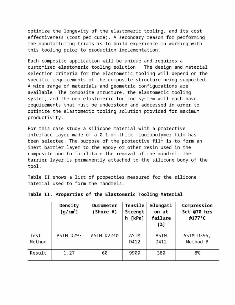
Table III. Dimensional Changes of the Mandrels used as Tooling for Repeated Composite Cure Cycles. Negative numbers indicate shrinkage. Changes are relative to zero cycle measurements (as produced mandrels) and represent the average between mandrels.
Dimension/Cure Cycle
0 2 4 6 8 10
Height (H) 4 cm 0.8% 0.3% 0.1% 0% 0%
Width (W) 4 cm 0.4% 0.6% 0.4% 0.5% 0.8%
Length (L) 65 cm -0.4% -0.6% -0.6% -0.3% -0.8%
It has been observed that the height of the mandrels growths initially, but stabilizes at the as-molded height level. At the same time, the width increases by less than 1% over 10 cycles. Both observations could be due to the pressurization that affects preferentially the height dimension at temperature. At the same time, the mandrels shrink in length direction less than 1% when subjected to 10 composite curing cycles. This is assumed to be due to the continued cross-linking of the elastomer during the heat cycles while the mandrel is partially restrained, resulting in compression set.
3.3 Composite Manufacturing TrialsThere are factors affecting the design of the trapped elastomeric tooling that are very difficult or impossible to predict. For example, the interaction between the tooling and the composite during heat-up and the related degree of restrain in longitudinal direction is commonly evaluated using experimental trials. As a result, it has been repeatedly observed that compensations for CTE are required to be much higher in the cross section than in the length. Although elastomeric tooling exhibits isotropic behavior with respect to CTE when unrestrained due to the fluid-like incompressibility of elastomers, any inhibition of the length growth manifests itself as increased growth in the cross-section. This inhibition depends on the composite system used, the OML mold design, pressure, the resin’s gel temperature etc.
Representative results for this interaction can be obtained on a flat plate composite, as long as the CTE of the composite and the temperature profile are matched. Multiple tooling reuse cycles can also be run on the same mandrel to reveal dimensional stability over time thereby predicting cycle life and to add dimensional compensation to the design.
The stiffened composite structure produced with different mandrel cross sections is shown in Figure 3.
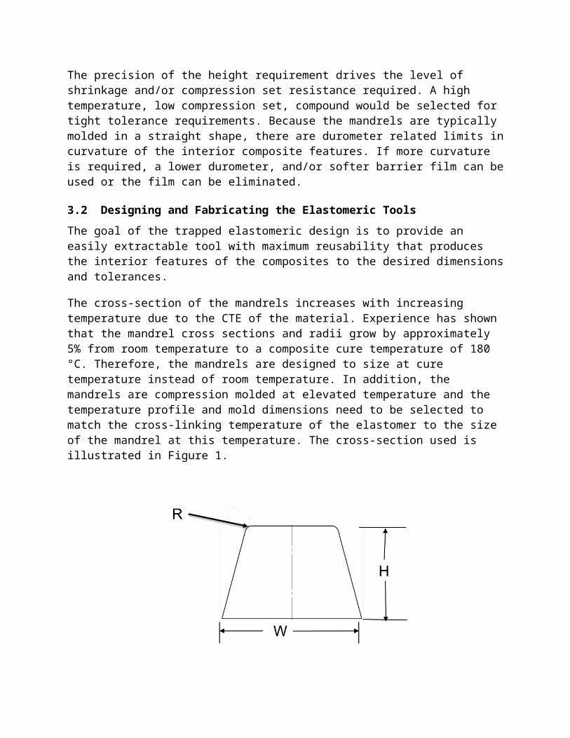
Figure 3. Hat Stiffened Composite Structure.
The overall dimensions of the panel were 61 cm in length, 121 cm in width, and 5 cm in height for the tallest hat stiffener and 2.3 cm for the smallest hat height. Sections with the 4 cm high mandrel tools have been repeatedly produced to evaluate the variation of the inside dimensions of the cavity produced with the same tool. The results are summarized in Table IV.
Table IV. Dimensional Changes of the Composite Cavities during Repeated Composite Cure Cycles. Changes are relative between cycles.
Dimension/Cure Cycle
2 4 6 8 10
Height (H) 0.4% 0.2% 0.1% 0.2% 0.3%
Width (W) 0.5% 0.1% -0.1% 0.2% 0.1%
The variation in width and height observed was less than ±1%. The radii were within 0.3 mm (<1%) throughout.
4. CONCLUSIONS
Each of the trapped tooling technologies used to form interior features has its unique features that makes it suitable for specific applications at specific production rates and tolerance requirements.
Elastomeric mandrels can be used to form hat-stiffened structures. The dimensions of the interior composite features can be controlled within tolerances of better than ±1% in height and width. The outside hat dimensions are not impacted by the trapped tooling in a part-level IML tool that
includes hard-tool features to hold the hat stiffeners. In the part-level OML tool used in this study, the final hat height is mostly determined by the per-ply thickness consistency and the mandrel tolerance. The mandrel tolerance contribution to these dimensions is less than ±1%.
The interior Radii tolerances are primarily driven by the ply forming, fillet forming technique, and exterior bagging approaches. Ply bridging can also be a factor. In the part-level OML tool application investigated here, tolerance better than 0.3 mm can be achieved. These tolerances are smaller with a part-level IML approach.
It was observed that the cycle to cycle variation in the mandrel measurements was greater than that observed in the cured composite laminate. This could be attributed to the inherent challenge of measuring a low modulus high CTE mandrel and/or the heat induced shape memory of the elastomers.
The optimum tolerances for a cost effective production are achieved if trials are conducted to evaluate curing cycle dependent shrinkage of the re-usable tools. On average 0.1% of shrinkage has been observed per cycle. The predicted cycle life of the mandrels depends on this shrinkage and its relationship to the tolerance requirements.
It was observed that the mandrels can be extracted by applying a force of less than 1 kp. The interior of the hats had no visible mark-up from the mandrels. The height and width of the outside and inside of the hats were within ±1% of the target dimensions. The largest discrepancy was found at the sides due to limited bulging. The internal and external radii were within 0.3 mm of the target.
5. REFERENCES
1. Michael Tupper, Robert Taylor, Dana Turse, Rory Barrett, Larry G. Adams “Reflector manufactured using multiple use precision extractable tooling”, US20140360665 A1, Dec. 11, 2014
2. Michael Tupper; Rory Barrett; Larry G. Adams; Robert Taylor; Dana Turse; “Multiple Use Precsion Extractable Tooling” US Patent 2013/0153144 A1
3. Mark W. Edwards, “Disposable Mandrels; A Case Study Utilizing Eutectic Salt”; TE89-506 Tooling for Composites 1989 Long Beach, CA, Society of Manufacturing Engineers, Dearborn, MI 1989.
4. A. Brent Strong, “Fundamentals of Composite Manufacturing Materials, Methods, and Applications, 2nd Edition, Society of manufacturing Engineers, 2008,
5. Douglas McCarville, J. Carlos Guzman, Alexandra Dillon, and Ryan Tidwell, The Boeing Company, Smart Tooling for Fluted Core Composite Cryotank and Dry Structure Manufacture” Thomas Margraf, Spintech LLC; Conference: CAMX 2015 - Dallas, TX - October 27-29, SKU/Code: TP15-0376
6. Sara Black “New options for trapped tooling”, http://www.compositesworld.com/articles/new-options-for-trapped-tooling, July 2011.
7. Matt Wallen , Jens Rossfeldt , Carl Aune , Zachary N. Wing, “Flexible Manufacturing of Hollow Composites Via Soluble Tooling” Conference: SAMPE 2013 - Long Beach CA - June 6-9 / 2013, SKU/Code: 58-3382
8. Brewster, Jebediah, “Design and Manufacture of Structural Efficient Tapered Struts”; NASA Langley Research Center, Hampton, VA 23681-2199, Contract: NNL04AA12B; 1-12-2009
9. Gregory J. Artz, John L. Lombardi, K. Ranji Vaidyanathan, Joseph Walish; Water Soluble Tooling Materials For Composite Structures”; US Patent EP20020726601, September 8, 2010.
10. L. Clements; “Trapped Tooling; Building the Unbuildable, New designs, new tooling materials, new approaches.” Composites Manufacturing; Published Jun. 2005.
11. Technical Application Guide, “Soluble Cores & Mandrels for Hollow Composite Parts”, Doc. No. TAG 02-01, http://www.techforever.com/userfiles/image/anli/PDF/SSYS-TAG-SolubleCores-04-11.pdf, 4/19/2011 Rev NC