Embed Size (px)
Citation preview

Parabolic Trough VSHOT Optical Characterization in
2005-2006
Tim Wendelin
NREL/PR-550-40024Presented at the 2006 Parabolic Trough Technology Workshop held on February 14-16, 2006, in Incline Village, Nevada.

Disclaimer and Government License
This work has been authored by Midwest Research Institute (MRI) under Contract No. DE-AC36-99GO10337 with the U.S. Department of Energy (the “DOE”). The United States Government (the “Government”) retains and the publisher, by accepting the work for publication, acknowledges that the Government retains a non-exclusive, paid-up, irrevocable, worldwide license to publish or reproduce the published form of this work, or allow others to do so, for Government purposes.
Neither MRI, the DOE, the Government, nor any other agency thereof, nor any of their employees, makes any warranty, express or implied, or assumes any liability or responsibility for the accuracy, completeness, or usefulness of any information, apparatus, product, or process disclosed, or represents that its use would not infringe any privately owned rights. Reference herein to any specific commercial product, process, or service by trade name, trademark, manufacturer, or otherwise does not constitute or imply its endorsement, recommendation, or favoring by the Government or any agency thereof. The views and opinions of the authors and/or presenters expressed herein do not necessarily state or reflect those of MRI, the DOE, the Government, or any agency thereof.

Trough Deployment/Operation Phases• Development
– R&D directed at maximizing performance/cost ratio– Requires testing tool(s) that provide detailed data on mirror contour,
mirror panel positioning• Manufacture/Installation
– QC testing of mirror panels (statistical sampling)– Module assembly– Requires fast, relatively simple optical characterization to reveal
problems & fix• Maintenance/Operation
– Many contributors to optical performance (e.g. specularity, mirror distortion, dirt, receiver shape/position)
– Large fields require simple, fast, effective tools to understand/fix problems & maximize performance

Optical Characterization Areas
• Mirror Optical Accuracy– Mirror contour– Mirror specularity
• Mirror Panel Alignment– Tilt– Position
• Receiver Positioning
Each issue is uniquely present in each phase

Trough Optical Characterization Issues• Single biggest challenge to fast, effective
characterization:– Lower concentration, line focus optics a large mirror
area and subsequent spatial test zone• Development
– Less of an issue• Manufacturing/Installation
– Somewhat of an issue• Operation/Maintenance
– BIG issue
• Point: Different tools needed for different phases

2005 Activities• Focused on development and manufacturing/installation phases
– Solargenix Advanced Parabolic Pilot Project– Industrial Solar Technology (IST) Parabolic Trough Technology
Development Project
• Improve/Modify/Update VSHOT for Parabolic Trough Field Measurements
• Use VSHOT to quantify for both Solargenix and Industrial Solar Technology designs– Mirror Optical Accuracy
• Mirror contour• Mirror specularity
– Mirror Panel Alignment• Tilt• Position
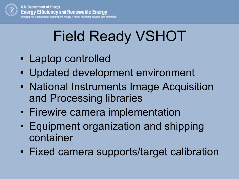
Field Ready VSHOT• Laptop controlled• Updated development environment• National Instruments Image Acquisition
and Processing libraries• Firewire camera implementation• Equipment organization and shipping
container• Fixed camera supports/target calibration

VSHOT• Originally
designed for point-focus concentrators
• Adapted for line-focus optics (samples one vertical slice at a time)
• Measures bi-directional surface slope, fits data to user defined shape, reports errors relative to that shape
Target
FireWire Camera
Test Article
He/Ne Laser
Laser Scanner
Tripod
Camera Support Arms
Control Computer
Shutter
Laser “Spot”

Solargenix Advanced Parabolic Trough Pilot Project• Leveraged off of the Nevada South
West Energy Partnership• Focuses on Manufacturing and
Installation Phase

Primary ObjectiveFull-Scale Testing….
.... Prior to 50 MW Plant Deployment

History and Linkage to National Program• 4-yr USA-Trough development (DOE/NREL)
• Major advances, but need full-scale tests– New lightweight structure– New drive– New controls– New concrete piers and support pedestals– New ball joint assemblies

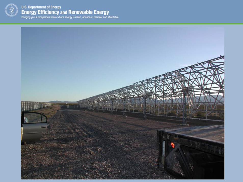
Project Hardware
• Advanced low-cost bearings installed• Construction completed (All 24 space frames: 2 SCAs)• Controllers and drives installed

VSHOT Test Objectives• Provide Solargenix with data on mirror
optical errors• Validate the “new and improved” field
ready VSHOT system• Lessons learned and identification of
improvements to assist future testing

First Round of TestsStarnet SpaceframeFebruary ‘05


Initial Test Results (Feb. ’05)• Only tested 3 columns
of glass mirrors• Not enough data to
come to any conclusions regarding mirror optical accuracy.
• Validated outdoor testing

2nd Round of Tests (July ’05)• Fully populated SCA (6 Starnet modules on
each side of drive)• Randomly select two mirror columns per module
(24 VSHOT profiles total)• Use data to quantify SCA twist and overall r.m.s
optical slope error• Identify specific contributors to slope error
(i.e. mirror panel distortion and/or misalignment)

.• Average
r.m.s. slope error = 4.4 mrad
• Average best fit focal length = 58.73”compared to design of 58.66”
Best Fit Focal Length (inches)
57.657.8
5858.258.458.658.8
5959.259.4
1 2 3 4 5 6 7 8 9 10 11 12 13 14 15 16 17 18 19 20 21 22 23 24 25 26
Average
R.M.S. Slope Error (mrads)
0123456789
10
1 2 3 4 5 6 7 8 9 10 11 12 13 14 15 16 17 18 19 20 21 22 23 24 25 26
Average

Conclusions (StarNet Spaceframe)
• Misalignment and distortion contribute to optical error
• 4.4 mrad r.m.s. slope error not unreasonable, but improvements could be made, especially in mirror panel misalignment
• Cannot say much about SCA twist due to drive drift during during test period. More tests necessary.

Gossamer Spaceframe
• Solargenix sought out new supplier for spaceframe
• Potential for lower assembly cost and better performance
• Tests on new modules perfomed in September, October ‘05

GossamerSpaceframe

VSHOT Improvements• Camera integrated
into target• Leveling tools built
into tripod• Much faster data
acquisition now possible
Target
FireWire Camera
Test Article
He/Ne Laser
Laser Scanner
Tripod
Camera Support Arms
Control Computer
Shutter
Laser “Spot”
Gossamer Results
• R.M.S. Slope Error approaching 3.0 mrad• Based partly on these results Solargenix
has decided to use Gossamer spaceframes in their 64 MW El Dorado Valley plant.

Industrial Solar Technology Parabolic Trough Development
Project• IST scaling up their unique structural
concentrator design to LS-2 type dimensions
• Requires optical characterization baseline of their existing product
• VSHOT used to provide data

• Current IST design is continuous surface reflector (no individual mirror panels)
• Concentrator module itself provides structural stiffness along module length (no support structure required)
• 10 VSHOT profiles taken along length of baseline IST module (using polymer film reflector) to characterize optical performance
Industrial Solar Technology Parabolic Trough Development
Project

Initial Module Results• Average r.m.s.
slope error = 4.46 mrads
• Average best fit focal length = 29.92” compared to design of 30.06”
• Very consistent along module length
R.M.S. Slope Error (mrads)
0
1
2
3
4
5
6
Profile#1
Repeatof
Profile#1
Profile#2
Profile#3
Profile#4
Profile#5
Profile#6
Profile#7
Repeatof
Profile#7
Profile#8
Profile#9
Profile#10
.
Best Fit Focal Length (inches)
20
22
24
26
28
30
32
Profile#1
Repeatof
Profile#1
Profile#2
Profile#3
Profile#4
Profile#5
Profile#6
Profile#7
Repeatof
Profile#7
Profile#8
Profile#9
Profile#10

• Consistent profile along module length
• Exhibits a flattening or parabolic curve at rims
• Better machining tolerances could improve this considerably
ResultsdZ/dY Error Relative to Best Fit Parabola
-50
-40
-30
-20
-10
0
10
20
30
40
50
-50 -40 -30 -20 -10 0 10 20 30 40 50
Y (inches)
dZ/d
Y Er
ror (
mill
iradi

Recent results• Two new improved
modules assembled and tested
• Significant improvement in slope error ~ 3.4 mrad r.m.s.
• Closer to design focal length of 30.35”
Not including re -tensioned profiles
0
1
2
3
4
5
6
7
8
1 2 3 4 5 6 7 8 9 10
Profile #
R.M
.S. S
lope
Err
or (m
rads
)
Average
Not including re-tensioned profiles
10
15
20
25
30
35
1 2 3 4 5 6 7 8 9 10
Profile #
Bes
t Fit
Foca
l Len
gth
(inch
es)
AverageDesign