Embed Size (px)
Citation preview
Presented by:
Radha Krishnan
Detroit Engineered Products
Parameterization & Optimization
of balloon expandable stent
May14 2012
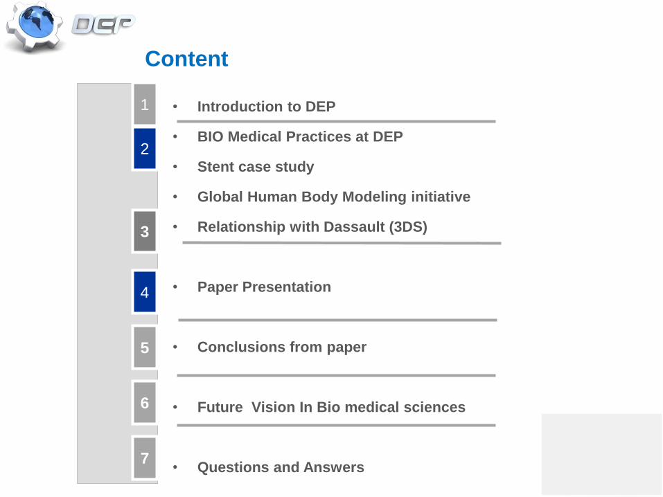
Content
• Introduction to DEP
• BIO Medical Practices at DEP
• Stent case study
• Global Human Body Modeling initiative
• Relationship with Dassault (3DS)
• Paper Presentation
• Conclusions from paper
• Future Vision In Bio medical sciences
• Questions and Answers
3
2
4
1
6
5
7
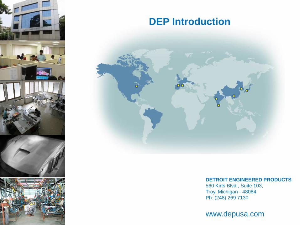
DETROIT ENGINEERED PRODUCTS
560 Kirts Blvd., Suite 103,
Troy, Michigan - 48084
Ph: (248) 269 7130
www.depusa.com
DEP Introduction
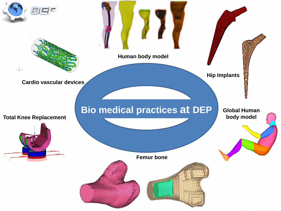
Bio medical practices at DEPTotal Knee Replacement
Femur bone
Cardio vascular devices
Global Human
body model
Human body model
Hip Implants
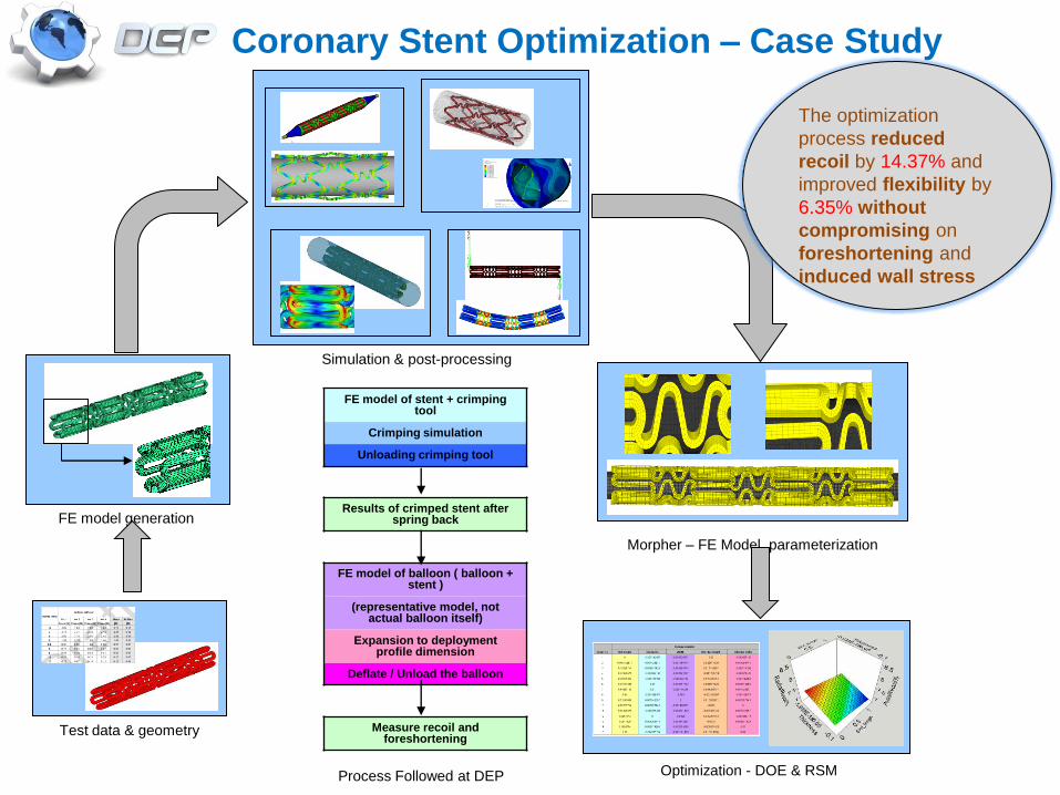
FE model of stent + crimping tool
Crimping simulation
Unloading crimping tool
Results of crimped stent after spring back
FE model of balloon ( balloon + stent )
(representative model, not actual balloon itself)
Expansion to deployment profile dimension
Deflate / Unload the balloon
Measure recoil and foreshortening
Test data & geometry
FE model generation
Simulation & post-processing
Morpher – FE Model parameterization
Optimization - DOE & RSM
Coronary Stent Optimization – Case Study
Process Followed at DEP
The optimization
process reduced
recoil by 14.37% and
improved flexibility by
6.35% without
compromising on
foreshortening and
induced wall stress
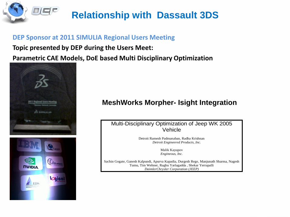
DEP Sponsor at 2011 SIMULIA Regional Users Meeting
Topic presented by DEP during the Users Meet:
Parametric CAE Models, DoE based Multi Disciplinary Optimization
Relationship with Dassault 3DS
MeshWorks Morpher- Isight Integration
Multi-Disciplinary Optimization of Jeep WK 2005 Vehicle
Detroit Ramesh Padmanaban, Radha Krishnan
Detroit Engineered Products, Inc.
Malik Kayupov
Engineous, Inc.
Sachin Gogate, Ganesh Kalpundi, Apurva Kapadia, Durgesh Rege, Manjunath Sharma, Nagesh
Tumu, Tim Wehner, Raghu Yarlagadda , Shekar Yerrapalli DaimlerChrysler Corporation (JEEP)
• Introduction to DEP
• BIO Medical Practices at DEP
– Stent case study
– Global Human Body Modeling initiative
• Relationship with Dassault (3DS)
Paper Presentation
• Conclusions from paper
• Future Vision In Bio medical sciences
• Questions and Answers
3
2
4
1
6
5
7
Introduction
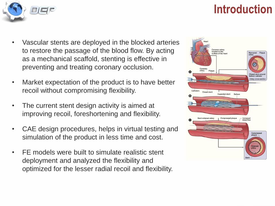
• Vascular stents are deployed in the blocked arteries
to restore the passage of the blood flow. By acting
as a mechanical scaffold, stenting is effective in
preventing and treating coronary occlusion.
• Market expectation of the product is to have better
recoil without compromising flexibility.
• The current stent design activity is aimed at
improving recoil, foreshortening and flexibility.
• CAE design procedures, helps in virtual testing and
simulation of the product in less time and cost.
• FE models were built to simulate realistic stent
deployment and analyzed the flexibility and
optimized for the lesser radial recoil and flexibility.
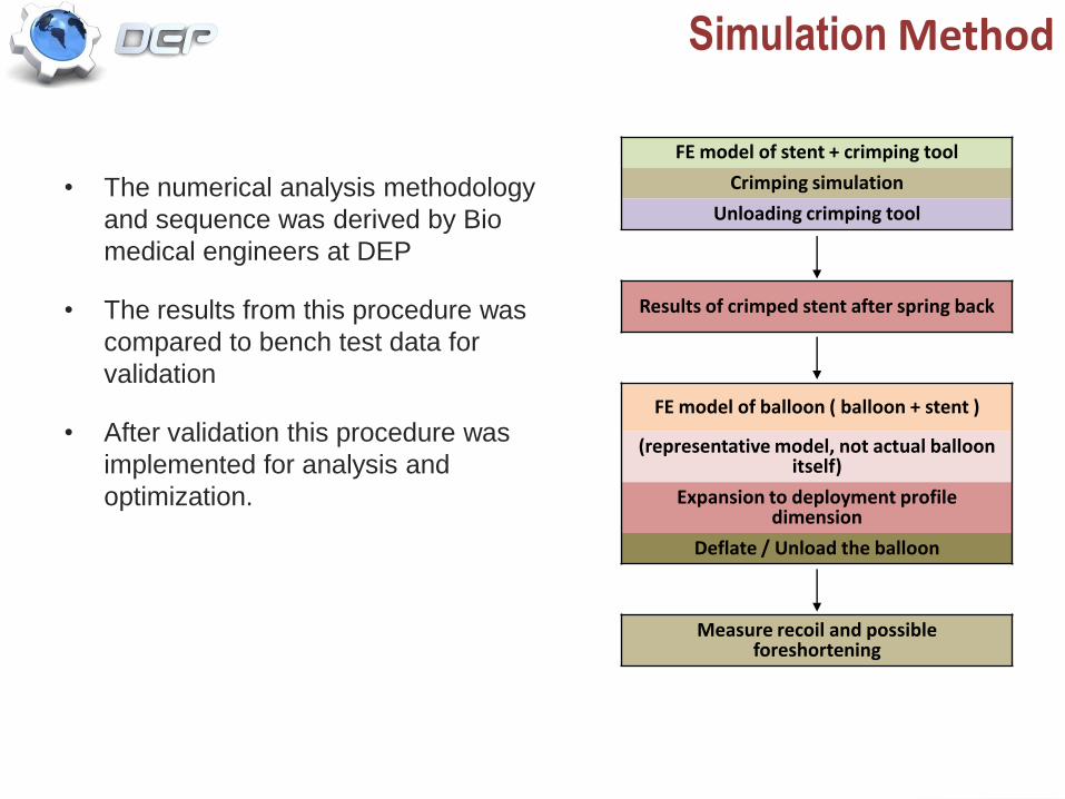
• The numerical analysis methodology
and sequence was derived by Bio
medical engineers at DEP
• The results from this procedure was
compared to bench test data for
validation
• After validation this procedure was
implemented for analysis and
optimization.
Simulation Method
FE model of stent + crimping tool
Crimping simulation
Unloading crimping tool
Results of crimped stent after spring back
FE model of balloon ( balloon + stent )
(representative model, not actual balloon itself)
Expansion to deployment profile dimension
Deflate / Unload the balloon
Measure recoil and possible foreshortening
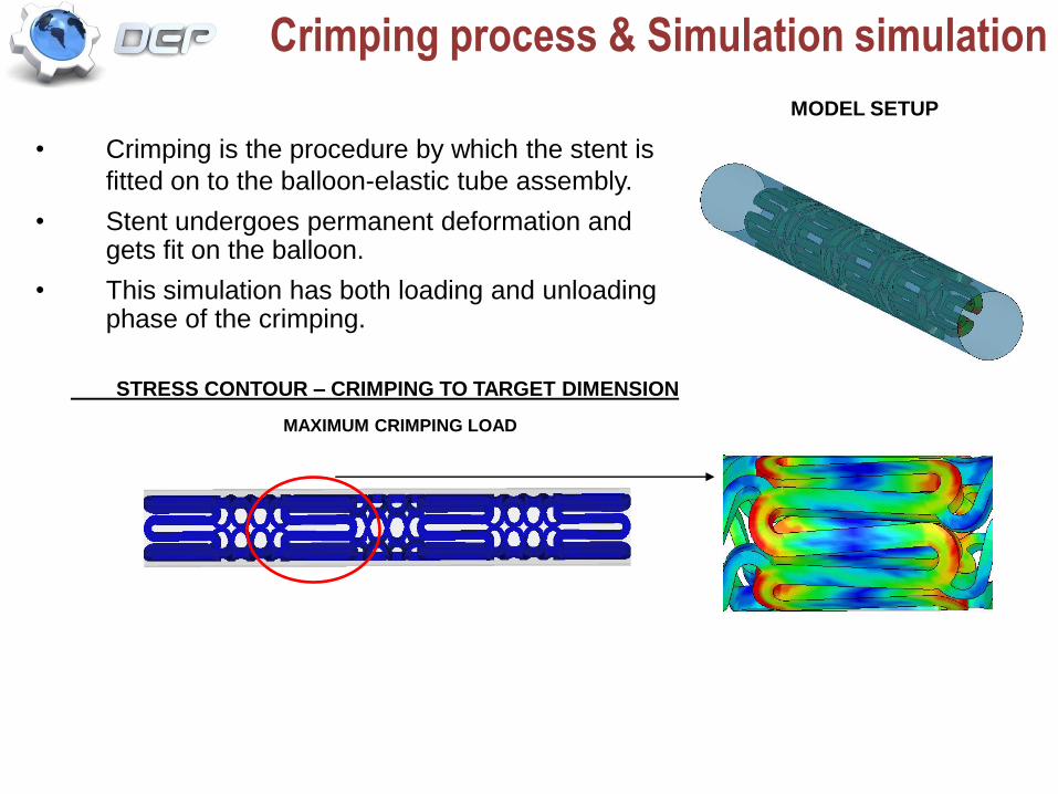
Crimping process & Simulation simulation
• Crimping is the procedure by which the stent is
fitted on to the balloon-elastic tube assembly.
• Stent undergoes permanent deformation and gets fit on the balloon.
• This simulation has both loading and unloading phase of the crimping.
MODEL SETUP
STRESS CONTOUR – CRIMPING TO TARGET DIMENSION
MAXIMUM CRIMPING LOAD
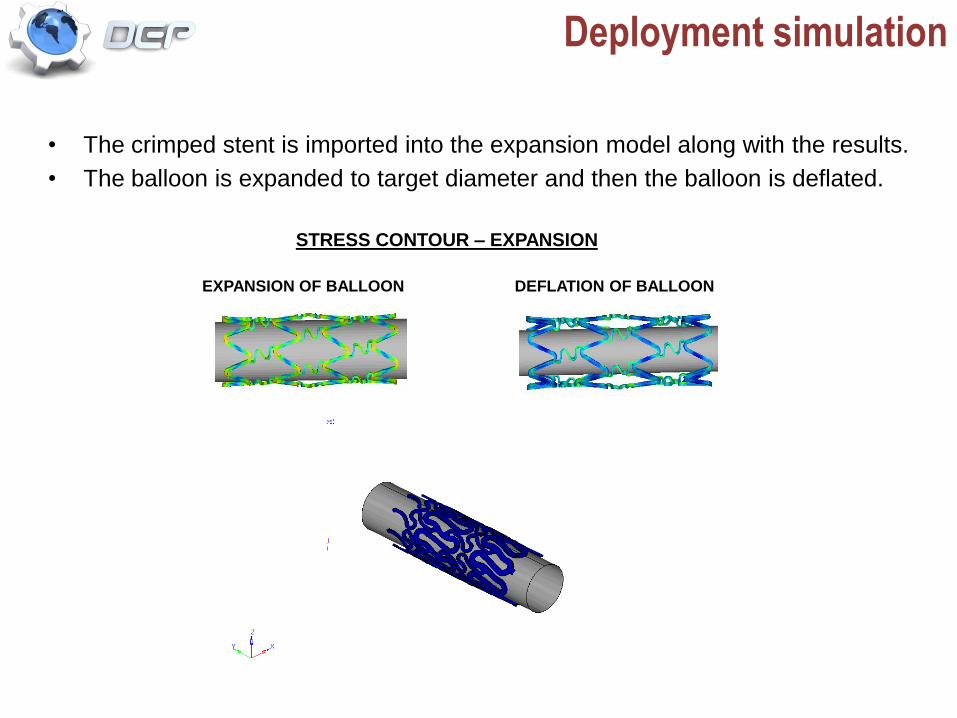
Deployment simulation
• The crimped stent is imported into the expansion model along with the results.
• The balloon is expanded to target diameter and then the balloon is deflated.
EXPANSION OF BALLOON DEFLATION OF BALLOON
STRESS CONTOUR – EXPANSION
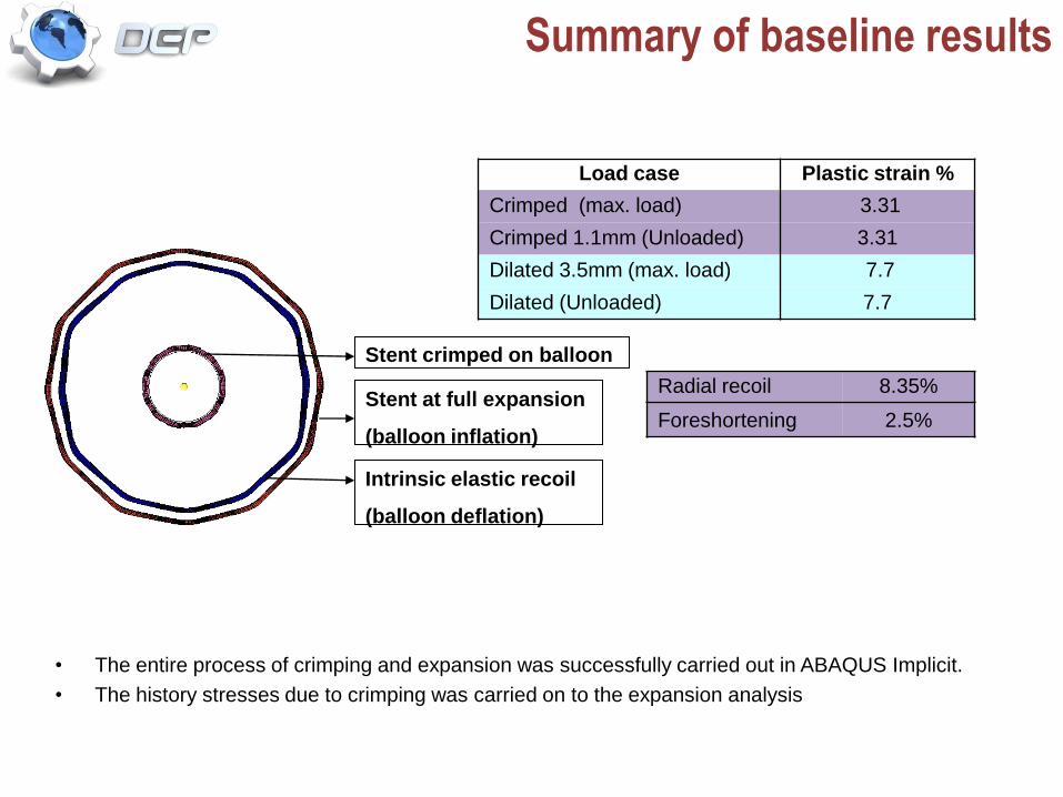
Summary of baseline results
Load case Plastic strain %
Crimped (max. load) 3.31
Crimped 1.1mm (Unloaded) 3.31
Dilated 3.5mm (max. load) 7.7
Dilated (Unloaded) 7.7
• The entire process of crimping and expansion was successfully carried out in ABAQUS Implicit.
• The history stresses due to crimping was carried on to the expansion analysis
Stent crimped on balloon
Stent at full expansion
(balloon inflation)
Intrinsic elastic recoil
(balloon deflation)
Radial recoil 8.35%
Foreshortening 2.5%
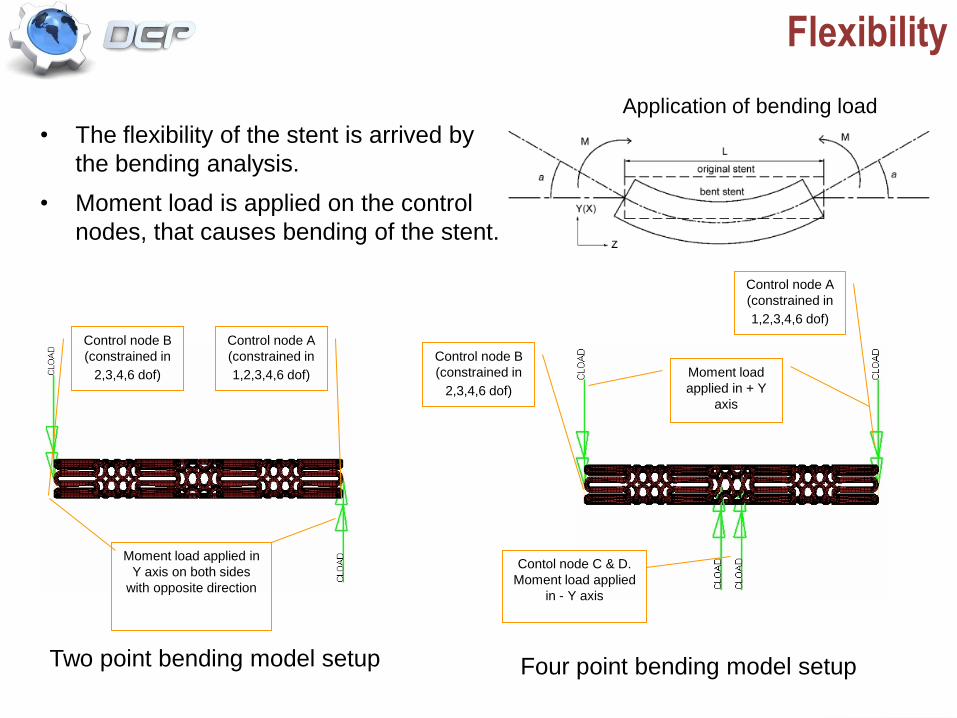
Flexibility
• The flexibility of the stent is arrived by
the bending analysis.
• Moment load is applied on the control
nodes, that causes bending of the stent.
Application of bending load
Control node B
(constrained in
2,3,4,6 dof)
Control node A
(constrained in
1,2,3,4,6 dof)
Moment load applied in
Y axis on both sides
with opposite direction
Two point bending model setup Four point bending model setup
Control node B
(constrained in
2,3,4,6 dof)
Control node A
(constrained in
1,2,3,4,6 dof)
Moment load
applied in + Y
axis
Contol node C & D.
Moment load applied
in - Y axis
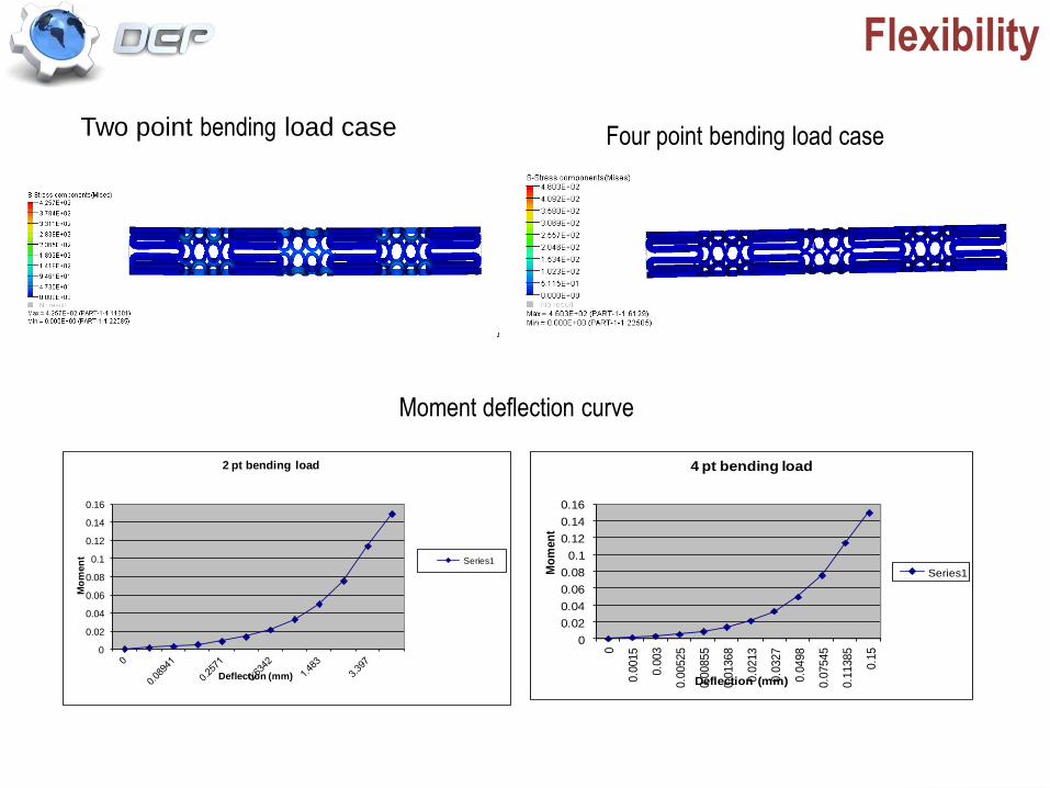
Flexibility
0
0.02
0.04
0.06
0.08
0.1
0.12
0.14
0.16
Mo
men
t
Deflection (mm)
2 pt bending load
Series1
0
0.02
0.04
0.06
0.08
0.1
0.12
0.14
0.16
0
0.0
015
0.0
03
0.0
0525
0.0
0855
0.0
1368
0.0
213
0.0
327
0.0
498
0.0
7545
0.1
1385
0.1
5
Mo
men
t
Deflection (mm)
4 pt bending load
Series1
Two point bending load case Four point bending load case
Moment deflection curve
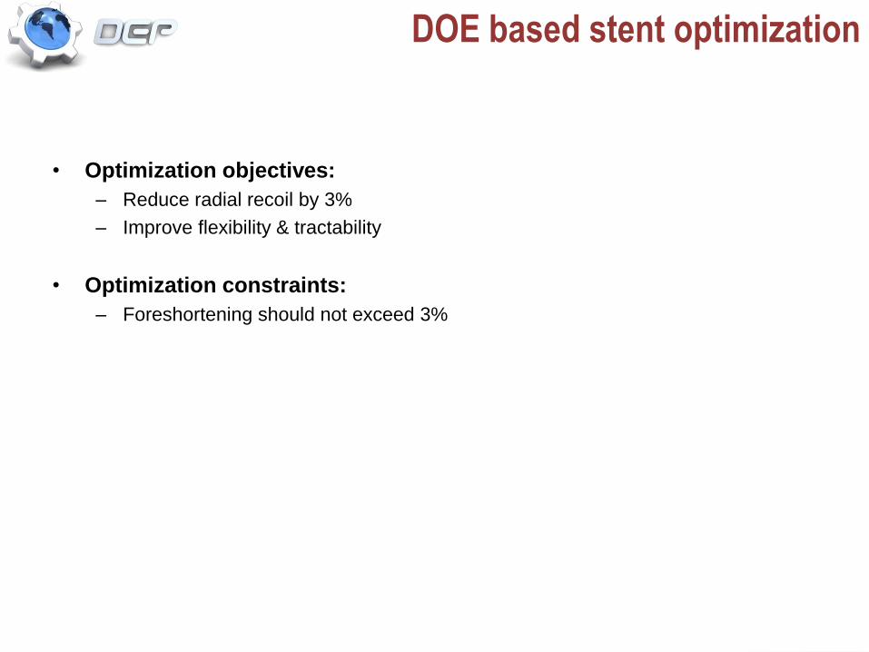
DOE based stent optimization
• Optimization objectives:
– Reduce radial recoil by 3%
– Improve flexibility & tractability
• Optimization constraints:
– Foreshortening should not exceed 3%
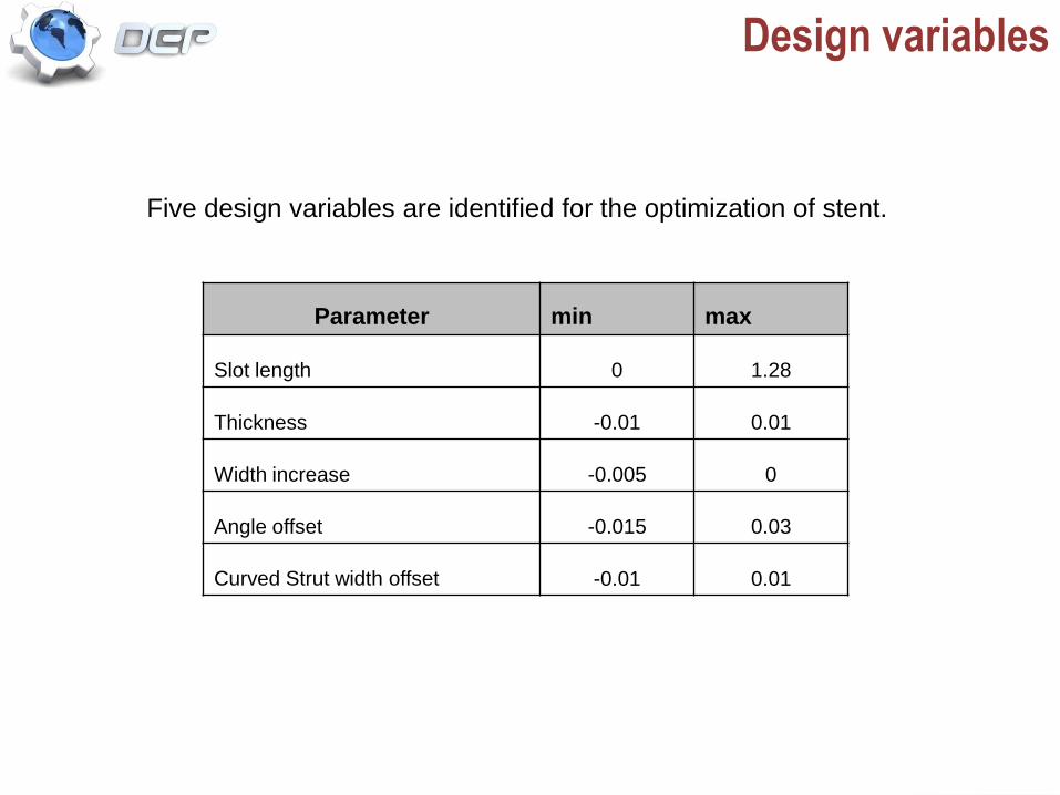
Design variables
Five design variables are identified for the optimization of stent.
Parameter min max
Slot length 0 1.28
Thickness -0.01 0.01
Width increase -0.005 0
Angle offset -0.015 0.03
Curved Strut width offset -0.01 0.01
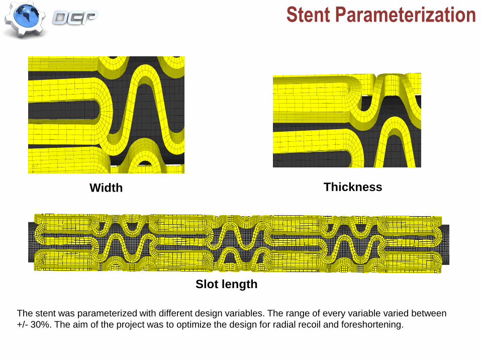
Width Thickness
Stent Parameterization
The stent was parameterized with different design variables. The range of every variable varied between
+/- 30%. The aim of the project was to optimize the design for radial recoil and foreshortening.
Slot length
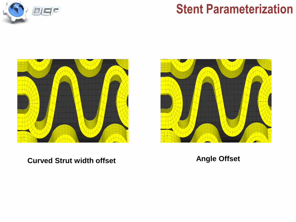
Curved Strut width offset Angle Offset
Stent Parameterization
DOE matrix
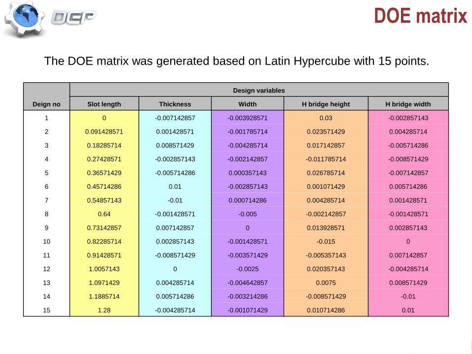
The DOE matrix was generated based on Latin Hypercube with 15 points.
Deign no
Design variables
Slot length Thickness Width H bridge height H bridge width
1 0 -0.007142857 -0.003928571 0.03 -0.002857143
2 0.091428571 0.001428571 -0.001785714 0.023571429 0.004285714
3 0.18285714 0.008571429 -0.004285714 0.017142857 -0.005714286
4 0.27428571 -0.002857143 -0.002142857 -0.011785714 -0.008571429
5 0.36571429 -0.005714286 0.000357143 0.026785714 -0.007142857
6 0.45714286 0.01 -0.002857143 0.001071429 0.005714286
7 0.54857143 -0.01 0.000714286 0.004285714 0.001428571
8 0.64 -0.001428571 -0.005 -0.002142857 -0.001428571
9 0.73142857 0.007142857 0 0.013928571 0.002857143
10 0.82285714 0.002857143 -0.001428571 -0.015 0
11 0.91428571 -0.008571429 -0.003571429 -0.005357143 0.007142857
12 1.0057143 0 -0.0025 0.020357143 -0.004285714
13 1.0971429 0.004285714 -0.004642857 0.0075 0.008571429
14 1.1885714 0.005714286 -0.003214286 -0.008571429 -0.01
15 1.28 -0.004285714 -0.001071429 0.010714286 0.01
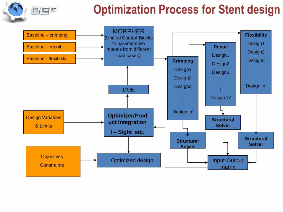
Optimization Process for Stent design
MORPHER(Unified Control-Blocks
to parameterize
models from different
load cases)
Baseline – crimping
Baseline – recoil
Baseline - flexibility
Flexibility
Design1
Design2
Design3
:
:
Design ‘n’
Recoil
Design1
Design2
Design3
:
:
Design ‘n’
Crimping
Design1
Design2
Design3
:
:
Design ‘n’Optimizer/Prod
uct Integration
I – Sight etc.
DOE
Design Variables
& Limits
Input-Output
matrix
Objectives
Constraints
Structural
Solver
Structural
Solver
Structural
Solver
Optimized design
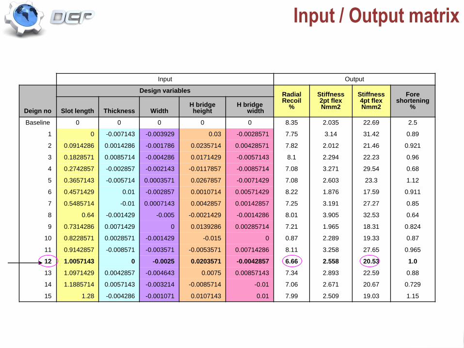
Input / Output matrix
Input Output
Deign no
Design variablesRadialRecoil
%
Stiffness2pt flexNmm2
Stiffness4pt flexNmm2
Foreshortening
%Slot length Thickness Width
H bridgeheight
H bridge width
Baseline 0 0 0 0 0 8.35 2.035 22.69 2.5
1 0 -0.007143 -0.003929 0.03 -0.0028571 7.75 3.14 31.42 0.89
2 0.0914286 0.0014286 -0.001786 0.0235714 0.00428571 7.82 2.012 21.46 0.921
3 0.1828571 0.0085714 -0.004286 0.0171429 -0.0057143 8.1 2.294 22.23 0.96
4 0.2742857 -0.002857 -0.002143 -0.0117857 -0.0085714 7.08 3.271 29.54 0.68
5 0.3657143 -0.005714 0.0003571 0.0267857 -0.0071429 7.08 2.603 23.3 1.12
6 0.4571429 0.01 -0.002857 0.0010714 0.00571429 8.22 1.876 17.59 0.911
7 0.5485714 -0.01 0.0007143 0.0042857 0.00142857 7.25 3.191 27.27 0.85
8 0.64 -0.001429 -0.005 -0.0021429 -0.0014286 8.01 3.905 32.53 0.64
9 0.7314286 0.0071429 0 0.0139286 0.00285714 7.21 1.965 18.31 0.824
10 0.8228571 0.0028571 -0.001429 -0.015 0 0.87 2.289 19.33 0.87
11 0.9142857 -0.008571 -0.003571 -0.0053571 0.00714286 8.11 3.258 27.65 0.965
12 1.0057143 0 -0.0025 0.0203571 -0.0042857 6.66 2.558 20.53 1.0
13 1.0971429 0.0042857 -0.004643 0.0075 0.00857143 7.34 2.893 22.59 0.88
14 1.1885714 0.0057143 -0.003214 -0.0085714 -0.01 7.06 2.671 20.67 0.729
15 1.28 -0.004286 -0.001071 0.0107143 0.01 7.99 2.509 19.03 1.15
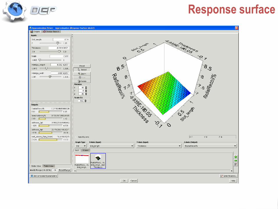
Response surface
Optimized Design
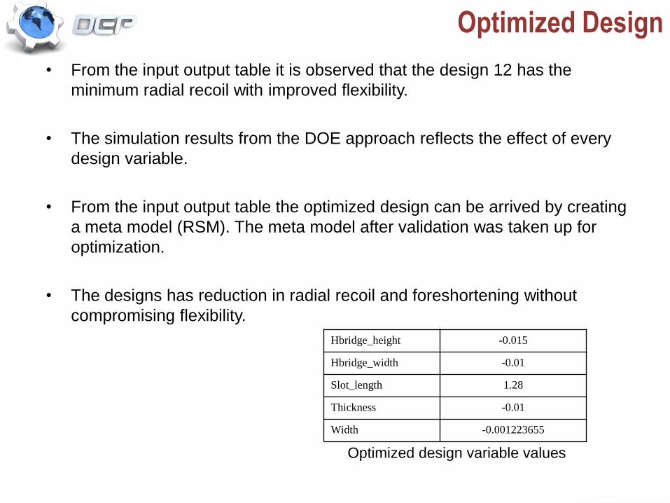
• From the input output table it is observed that the design 12 has the
minimum radial recoil with improved flexibility.
• The simulation results from the DOE approach reflects the effect of every
design variable.
• From the input output table the optimized design can be arrived by creating
a meta model (RSM). The meta model after validation was taken up for
optimization.
• The designs has reduction in radial recoil and foreshortening without
compromising flexibility.
Hbridge_height -0.015
Hbridge_width -0.01
Slot_length 1.28
Thickness -0.01
Width -0.001223655
Optimized design variable values
Conclusion & Future work
• The DOE based optimization technique is effective in finding the optimum
design of the stent with improved radial recoil and flexibility.
• The response surface method will be followed to find the global optimum
design.
• The study was conducted in 3 weeks time. The model building and the
baseline runs were completed in 1 week. Parameterization and DOE
generation were completed in 2 weeks.
• Study of blood vessel stress due to stenting is another parameter that is in
process, which will also be incorporated in the MDO approach in future.
Hyper elastic material model will be used for modeling the blood vessel.
• Cardio vascular devices :
– The benchmarked numerical analyses scheme coupled with optimizer (Isight)
and MeshWorks as a way forward for optimizing stent characteristics
– Stent rolling tool in MeshWorks drastically cuts down the time to build stent 3D
models from 2D line data.
– Design process for NiTinol (SMA) stent.
– Investigation into drug eluting stents.
• Human Body Modeling :
– MeshWorks process based on scaling and morphing successfully extended to
build non standard and standard percentile human body models.
– Our own hex mesher to build human body models.
– Continue engagement with 3DS team at Rhode Islands on the human body
model
• Implants :
– Patient specific implant initiative
Future Vision In Bio medical sciences

Build a Stent 3D FE model from 2D Line data in MeshWorks
2D line data of stent
Stent Rolling Tool in MeshWorks
Creation of 3D Hexahedral Mesh of the stent in
MeshWorks
3D Hexahedral Mesh Quality Improvement in
MeshWorks
Performance Evaluation
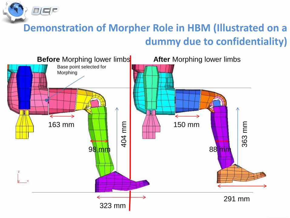
Demonstration of Morpher Role in HBM (Illustrated on a dummy due to confidentiality)
Before Morphing lower limbs After Morphing lower limbs
323 mm
98 mm
404 m
m163 mm 150 mm
Base point selected for
Morphing
363 m
m
291 mm
88 mm

Q and A

Thank you.