Embed Size (px)
Citation preview
Proceedings of the International Association for Shell and Spatial Structures (IASS) Symposium 2009, Valencia Evolution and Trends in Design, Analysis and Construction of Shell and Spatial Structures
28 September – 2 October 2009, Universidad Politecnica de Valencia, Spain Alberto DOMINGO and Carlos LAZARO (eds.)
Parametric analysis of cable net roofs suspended
from arches with block and tackle suspension
system
Krisztián HINCZ
Department of Structural Mechanics, Budapest University of Technology and Economics,
Műegyetem rkp. 3., Budapest 1111, Hungary
Abstract
This paper deals with the parametric analysis of special arch-supported cable net structures. Based on an invention of Kolozsváry [5], the cable net is suspended from the arches with block and tackle suspension system. The aim of this special suspension system is to minimize the bending moments in the supporting arches by converting the random meteorological roof loads into nearly uniform, symmetric arch loads, based on the well-known principle of block and tackle. Cable net structures supported by a single truss arch are analyzed by the help of the dynamic relaxation method. Structures with the same topology but different free spans are analyzed. The internal forces of the supporting arch due to different external loads are calculated. The effect of the friction between the pulley and its shaft on the behavior of the structures and on the efficiency of the block and tackle suspension system is presented.
Keywords: block and tackle suspension system, tensile structure, truss arch, dynamic relaxation method, large displacement theory
1. Introduction
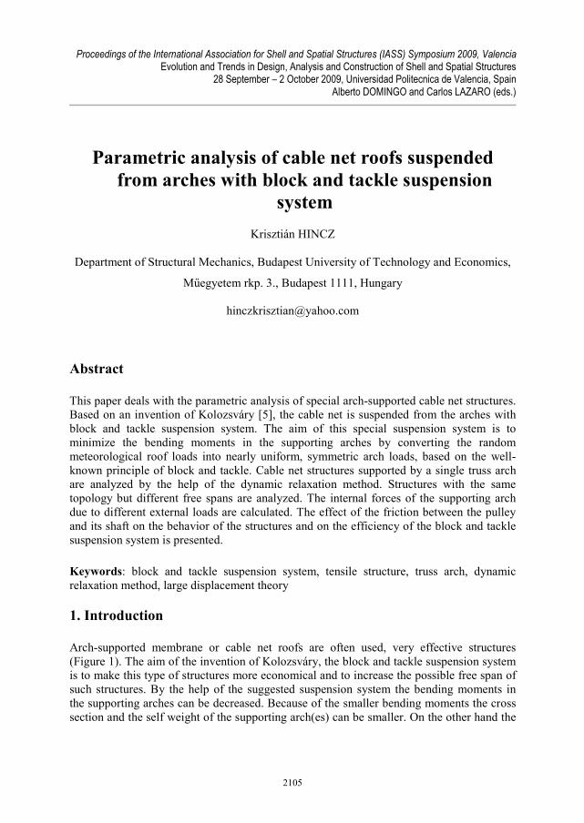
Arch-supported membrane or cable net roofs are often used, very effective structures (Figure 1). The aim of the invention of Kolozsváry, the block and tackle suspension system is to make this type of structures more economical and to increase the possible free span of such structures. By the help of the suggested suspension system the bending moments in the supporting arches can be decreased. Because of the smaller bending moments the cross section and the self weight of the supporting arch(es) can be smaller. On the other hand the
2105
Proceedings of the International Association for Shell and Spatial Structures (IASS) Symposium 2009, Valencia Evolution and Trends in Design, Analysis and Construction of Shell and Spatial Structures
tensile roof can be erected simply and fast by the help of the continuous suspension cable and the pulleys of the block and tackle suspension system.
Figure 1: Arch supported tensile roof with conventional, individual suspension cables (Bank of Amerika Pavilion in Boston, MA)
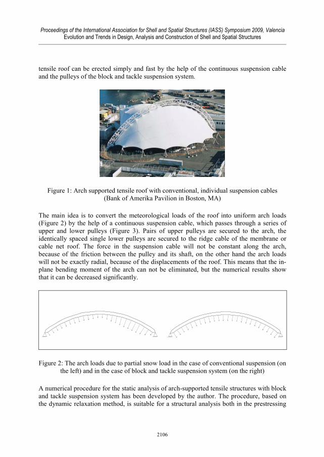
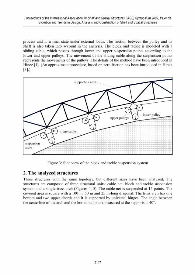
The main idea is to convert the meteorological loads of the roof into uniform arch loads (Figure 2) by the help of a continuous suspension cable, which passes through a series of upper and lower pulleys (Figure 3). Pairs of upper pulleys are secured to the arch, the identically spaced single lower pulleys are secured to the ridge cable of the membrane or cable net roof. The force in the suspension cable will not be constant along the arch, because of the friction between the pulley and its shaft, on the other hand the arch loads will not be exactly radial, because of the displacements of the roof. This means that the in-plane bending moment of the arch can not be eliminated, but the numerical results show that it can be decreased significantly.
Figure 2: The arch loads due to partial snow load in the case of conventional suspension (on the left) and in the case of block and tackle suspension system (on the right)
A numerical procedure for the static analysis of arch-supported tensile structures with block and tackle suspension system has been developed by the author. The procedure, based on the dynamic relaxation method, is suitable for a structural analysis both in the prestressing
2106
Proceedings of the International Association for Shell and Spatial Structures (IASS) Symposium 2009, Valencia Evolution and Trends in Design, Analysis and Construction of Shell and Spatial Structures
process and in a final state under external loads. The friction between the pulley and its shaft is also taken into account in the analysis. The block and tackle is modeled with a sliding cable, which passes through lower and upper suspension points according to the lower and upper pulleys. The movement of the sliding cable along the suspension points represents the movements of the pulleys. The details of the method have been introduced in Hincz [4]. (An approximate procedure, based on zero friction has been introduced in Hincz [3].)
Figure 3: Side view of the block and tackle suspension system
2. The analyzed structures
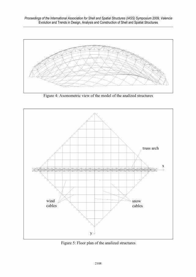
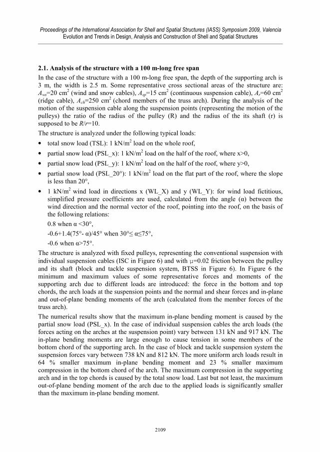
Three structures with the same topology, but different sizes have been analyzed. The structures are composed of three structural units: cable net, block and tackle suspension system and a single truss arch (Figures 4, 5). The cable net is suspended at 15 points. The covered area is square with a 100 m, 50 m and 25 m-long diagonal. The truss arch has one bottom and two upper chords and it is supported by universal hinges. The angle between the centerline of the arch and the horizontal plane measured at the supports is 40°.
2107
Proceedings of the International Association for Shell and Spatial Structures (IASS) Symposium 2009, Valencia Evolution and Trends in Design, Analysis and Construction of Shell and Spatial Structures
Figure 4: Axonometric view of the model of the analized structures
Figure 5: Floor plan of the analized structures
2108
Proceedings of the International Association for Shell and Spatial Structures (IASS) Symposium 2009, Valencia Evolution and Trends in Design, Analysis and Construction of Shell and Spatial Structures
2.1. Analysis of the structure with a 100 m-long free span
In the case of the structure with a 100 m-long free span, the depth of the supporting arch is 3 m, the width is 2.5 m. Some representative cross sectional areas of the structure are: Aws=20 cm
2 (wind and snow cables), Asp=15 cm2 (continuous suspension cable), Ar=60 cm
2 (ridge cable), Ach=250 cm
2 (chord members of the truss arch). During the analysis of the motion of the suspension cable along the suspension points (representing the motion of the pulleys) the ratio of the radius of the pulley (R) and the radius of the its shaft (r) is supposed to be R/r=10.
The structure is analyzed under the following typical loads:
• total snow load (TSL): 1 kN/m2 load on the whole roof,
• partial snow load (PSL_x): 1 kN/m2 load on the half of the roof, where x>0,
• partial snow load (PSL_y): 1 kN/m2 load on the half of the roof, where y>0,
• partial snow load (PSL_20°): 1 kN/m2 load on the flat part of the roof, where the slope is less than 20°,
• 1 kN/m2 wind load in directions x (WL_X) and y (WL_Y): for wind load fictitious, simplified pressure coefficients are used, calculated from the angle (α) between the wind direction and the normal vector of the roof, pointing into the roof, on the basis of the following relations:
0.8 when α <30°,
-0.6+1.4(75°- α)/45° when 30°≤ α≤75°,
-0.6 when α>75°.
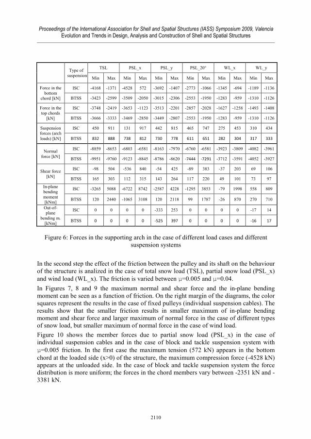
The structure is analyzed with fixed pulleys, representing the conventional suspension with individual suspension cables (ISC in Figure 6) and with µ=0.02 friction between the pulley and its shaft (block and tackle suspension system, BTSS in Figure 6). In Figure 6 the minimum and maximum values of some representative forces and moments of the supporting arch due to different loads are introduced: the force in the bottom and top chords, the arch loads at the suspension points and the normal and shear forces and in-plane and out-of-plane bending moments of the arch (calculated from the member forces of the truss arch).
The numerical results show that the maximum in-plane bending moment is caused by the partial snow load (PSL_x). In the case of individual suspension cables the arch loads (the forces acting on the arches at the suspension point) vary between 131 kN and 917 kN. The in-plane bending moments are large enough to cause tension in some members of the bottom chord of the supporting arch. In the case of block and tackle suspension system the suspension forces vary between 738 kN and 812 kN. The more uniform arch loads result in 64 % smaller maximum in-plane bending moment and 23 % smaller maximum compression in the bottom chord of the arch. The maximum compression in the supporting arch and in the top chords is caused by the total snow load. Last but not least, the maximum out-of-plane bending moment of the arch due to the applied loads is significantly smaller than the maximum in-plane bending moment.
2109
Proceedings of the International Association for Shell and Spatial Structures (IASS) Symposium 2009, Valencia Evolution and Trends in Design, Analysis and Construction of Shell and Spatial Structures
Type of suspension
TSL PSL_x PSL_y PSL_20° WL_x WL_y
Min Max Min Max Min Max Min Max Min Max Min Max
Force in the bottom
chord [kN]
ISC -4168 -1371 -4528 572 -3692 -1407 -2773 -1066 -1345 -694 -1189 -1136
BTSS -3423 -2599 -3509 -2050 -3015 -2306 -2553 -1950 -1283 -959 -1310 -1126
Force in the top chords
[kN]
ISC -3748 -2419 -3653 -1123 -3513 -2201 -2857 -2028 -1627 -1258 -1493 -1408
BTSS -3666 -3333 -3469 -2850 -3449 -2807 -2553 -1950 -1283 -959 -1310 -1126
Suspension forces (arch loads) [kN]
ISC 450 911 131 917 442 815 465 747 275 453 310 434
BTSS 832 888 738 812 730 778 611 651 282 304 317 333
Normal force [kN]
ISC -8859 -8653 -6803 -6581 -8163 -7970 -6760 -6581 -3923 -3809 -4082 -3961
BTSS -9951 -9760 -9123 -8845 -8786 -8620 -7444 -7291 -3712 -3591 -4052 -3927
Shear force [kN]
ISC -98 504 -536 840 -54 425 -89 383 -37 203 69 106
BTSS 165 303 112 315 143 264 117 220 49 101 73 97
In-plane bending moment [kNm]
ISC -3265 5088 -6722 8742 -2587 4228 -1295 3853 -79 1998 558 809
BTSS 120 2440 -1065 3108 120 2118 99 1787 -26 870 270 710
Out-of-plane
bending m. [kNm]
ISC 0 0 0 0 -333 253 0 0 0 0 -17 14
BTSS 0 0 0 0 -525 397 0 0 0 0 -16 17
Figure 6: Forces in the supporting arch in the case of different load cases and different suspension systems
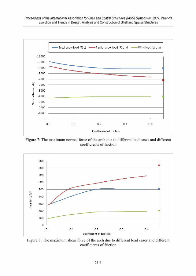
In the second step the effect of the friction between the pulley and its shaft on the behaviour of the structure is analized in the case of total snow load (TSL), partial snow load (PSL_x) and wind load (WL_x). The friction is varied between µ=0.005 and µ=0.04.
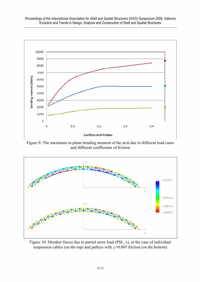
In Figures 7, 8 and 9 the maximum normal and shear force and the in-plane bending moment can be seen as a function of friction. On the right margin of the diagrams, the color squares represent the results in the case of fixed pulleys (individual suspension cables). The results show that the smaller friction results in smaller maximum of in-plane bending moment and shear force and larger maximum of normal force in the case of different types of snow load, but smaller maximum of normal force in the case of wind load.
Figure 10 shows the member forces due to partial snow load (PSL_x) in the case of individual suspension cables and in the case of block and tackle suspension system with µ=0.005 friction. In the first case the maximum tension (572 kN) appears in the bottom chord at the loaded side (x>0) of the structure, the maximum compression force (-4528 kN) appears at the unloaded side. In the case of block and tackle suspension system the force distribution is more uniform; the forces in the chord members vary between -2351 kN and -3381 kN.
2110
Proceedings of the International Association for Shell and Spatial Structures (IASS) Symposium 2009, Valencia Evolution and Trends in Design, Analysis and Construction of Shell and Spatial Structures
Figure 7: The maximum normal force of the arch due to different load cases and different
coefficients of friction
Figure 8: The maximum shear force of the arch due to different load cases and different
coefficients of friction
2111
Proceedings of the International Association for Shell and Spatial Structures (IASS) Symposium 2009, Valencia Evolution and Trends in Design, Analysis and Construction of Shell and Spatial Structures
Figure 9: The maximum in-plane bending moment of the arch due to different load cases
and different coefficients of friction
Figure 10: Member forces due to partial snow load (PSL_x), in the case of individual suspension cables (on the top) and pulleys with µ=0.005 friction (on the bottom)
2112
Proceedings of the International Association for Shell and Spatial Structures (IASS) Symposium 2009, Valencia Evolution and Trends in Design, Analysis and Construction of Shell and Spatial Structures
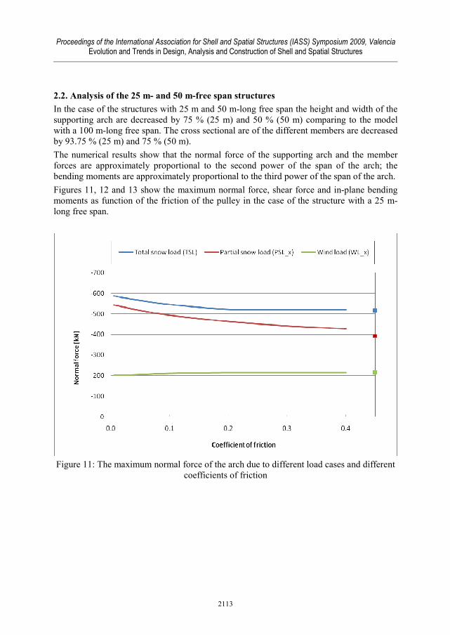
2.2. Analysis of the 25 m- and 50 m-free span structures
In the case of the structures with 25 m and 50 m-long free span the height and width of the supporting arch are decreased by 75 % (25 m) and 50 % (50 m) comparing to the model with a 100 m-long free span. The cross sectional are of the different members are decreased by 93.75 % (25 m) and 75 % (50 m).
The numerical results show that the normal force of the supporting arch and the member forces are approximately proportional to the second power of the span of the arch; the bending moments are approximately proportional to the third power of the span of the arch.
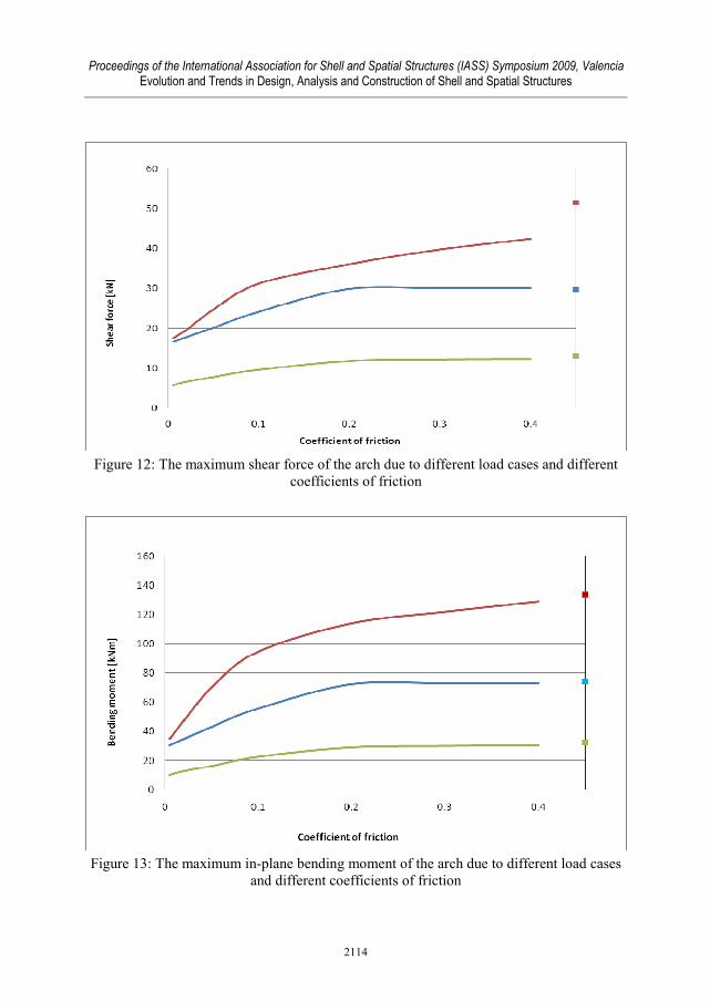
Figures 11, 12 and 13 show the maximum normal force, shear force and in-plane bending moments as function of the friction of the pulley in the case of the structure with a 25 m-long free span.
Figure 11: The maximum normal force of the arch due to different load cases and different
coefficients of friction
2113
Proceedings of the International Association for Shell and Spatial Structures (IASS) Symposium 2009, Valencia Evolution and Trends in Design, Analysis and Construction of Shell and Spatial Structures
Figure 12: The maximum shear force of the arch due to different load cases and different
coefficients of friction
Figure 13: The maximum in-plane bending moment of the arch due to different load cases
and different coefficients of friction
2114
Proceedings of the International Association for Shell and Spatial Structures (IASS) Symposium 2009, Valencia Evolution and Trends in Design, Analysis and Construction of Shell and Spatial Structures
3. Conclusion
The numerical results of the parametric analysis of arch supported tensile structures with individual suspension cables and block and tackle suspension system are introduced. The internal forces of the single supporting arch due to different external loads are analyzed by the help of a dynamic relaxation based numerical procedure developed by the author. The normal and shear force and the in-plane bending moment of the supporting arch are plotted as a function of friction between the pulley and its shaft in the block and tackle suspension system. The numerical results proved that the friction has a strong effect on the efficiency of the block and tackle suspension system; in the case of small friction the in-plane bending moments of the supporting arch can be decreased significantly.
Acknowledgement
Support by OTKA Grant No. PD-75305 is gratefully acknowledged.
References
[1] Barnes M.R., Form-finding and analysis of prestressed nets and membranes, Computers and Structures, 1988; 30; 685-695.
[2] Day A.S., An introduction to dynamic relaxation, The Engineer, 1965, 218-221.
[3] Hincz K., Arch-supported tensile structures with very long clear spans. Journal of the International Association of Shell and Spatial Structures, 2007; 48 (2): 89-98.
[4] Hincz K., Nonlinear analysis of cable net structures suspended from arches with block and tackle suspension system, taking into account the friction of the pulleys. Journal of Space Structures, (submitted)
[5] Kolozsváry Á., Roof arches without bending moments. Patent, 2006, WO/2006/136867.
2115


![library.tee.grlibrary.tee.gr/digital/m2401_2500/m2422/m2422_majowiecki.pdf · — suspended roofs — cable trusses — single and multilayer nets [2] Membrane structures — prestressed](https://img.pdfslide.net/doc/110x75/5f03f25d7e708231d40b8dff/a-suspended-roofs-a-cable-trusses-a-single-and-multilayer-nets-2-membrane.jpg)