Embed Size (px)
Citation preview
HHVVAACC SSYYSSTTEEMMSS BBAALLAANNCCIINNGG
MMCCSS 2233 0055 9933--11
AAUUTTHHOORR:: TTEERRHHAARRNN,, SSUUSSAANNNNEE
PART 1 GENERAL 1.01 SUMMARY
A. Testing adjusting, and balancing of air system.
B. Testing adjusting, and balancing of hydronic system.
C. Measurement of final operating conditions of HVAC system.
D. Sound measurement of equipment operating conditions.
E. Vibration measurement of equipment operating conditions. 1.02 REFERENCES
A. Associated Air Balance Council: AABC MN-1 National Standards for Testing and Balancing Heating, Ventilating, and air-Conditioning Systems.
B. National Environmental Balancing Bureau: NEBB – Pocedural Standards for Testing, Adjusting,
and Balancing of Environmental Systems. 1.03 SUBMITTALS
A. Reports
1. Four (4) copies of complete reports shall be submitted to the Owner's Representative for review. Applicable AABC, or NEBB test and balance forms shall be used. Report shall be signed and dated by the agency/engineer who supervised the work and the person who recorded the field data.
1.04 QUALITY ASSURANCE
A. Perform work in accordance with Reference Standards.
B. The work described in this section shall be performed by a firm who is certified by and a member of the Associated Air Balance Council (AABC), or NEBB, and shall be an independent subcontractor to the HVAC systems installing contractors on this project.
C. The balancing subcontractor shall not be the installing contractor.
D. Personnel shall be experienced and trained in the balancing of mechanical systems. All work shall
be done under the supervision of a certified test and balance engineer, and provide evidence of the certification.
E. All instruments used shall be accurately calibrated and maintained in good working.
F. Tests and adjustments shall begin after the systems are completed. The procedures followed shall
be as outlined in the ASHRAE Systems Handbook, which shall be considered as the minimum requirements.
MMCCSS 2233 0055 9933..DDOOCC RREEVV AA,, JJUULL 22001100
HHVVAACC SSYYSSTTEEMMSS BBAALLAANNCCIINNGG
MMCCSS 2233 0055 9933--22
AAUUTTHHOORR:: TTEERRHHAARRNN,, SSUUSSAANNNNEE
G. All instruments used for measurements shall be accurate, and identification and serial numbers of all instruments used and their last dates of calibration shall be submitted with the final report.
H. All personnel shall be currently certified by the AABC. Certificates of individuals shall be
submitted for approval prior to start of work. PART 2 PRODUCTS
Not Used. PART 3 EXECUTIONS
A. The HVAC systems, including all equipment, apparatus, and distribution systems shall be tested, balanced, and adjusted in accordance with procedural standards for testing, balancing, and adjusting of environmental systems in accordance with AABC National Standards for Field Measurement and Instrumentations Form 81266, Volume One. Systems shall include, but are not necessarily limited to, air handling systems, fans, chilled water and hot water systems and pumps.
B. Measure air volumes by means of the duct traverse method where possible. Seal duct access holes
with metal or plastic plugs or covers. The use of duct tape to seal access holes will NOT be permitted.
C. Main supply, return and exhaust ducts must be traversed. Summations of grille and diffuser air
quantities to determine total unit air quantities is not acceptable.
D. Make all necessary changes in pulleys, belts, dampers and valve settings, where necessary to obtain required air and water volumes.
E. The total air delivery in any particular fan system shall be obtained by adjustment of the particular
fan speed. The drive motor of each fan shall not be loaded over the corrected full load amperage rating of the motor involved.
F. For air systems utilizing varying quantities of outside air, the system shall be adjusted with the
outside air dampers adjusted to admit exact percentage of minimum outside air. In addition, set outside air damper to 100% outside air and record readings, noting any change in amps, static pressure and CFM readings. Large variations should be eliminated by proper adjustements.
G. Points of systems shall be balanced to within plus 10% or minus 5% of design conditions.
H. Perform the following tests and balance systems in accordance with the following:
1. Test and adjust blowers, pumps, fans and exhausters to design requirements.
2. Test and record motor current draw at each phase.
3. Record voltages (each phase) at each motor in the system.
4. Record voltages (each phase) at each motor in the system.
5. Make pitot tube traverse of main supply, return and exhausts to obtain design CFM at fans.
6. Test and record system static pressures at suction and discharge of fans, coils, automatic
dampers, filters and silencers.
MMCCSS 2233 0055 9933..DDOOCC RREEVV AA,, JJUULL 22001100
HHVVAACC SSYYSSTTEEMMSS BBAALLAANNCCIINNGG
MMCCSS 2233 0055 9933--33
AAUUTTHHOORR:: TTEERRHHAARRNN,, SSUUSSAANNNNEE
7. Test and adjust systems for design percentage of CFM outside air.
8. Adjust all supply, return and exhaust outlets to design CFM.
9. Adjust all VAV boxes to design CFM.
10. Check all dampers for proper operation and control sequence.
11. Adjust GPM to design at circuit setters and pumps.
I. Report Forms:
1. Reports shall contain, but need not be limited to the following information:
a. Equipment list.
b. Job-tailored system flow schematics with data points indicated.
c. Fans air handling units, furnace and pumps:
Manufacturer, size and HP. Amperage (nameplate, corrected full load and final operating). Motor current charateristics, starter size and heater size. RPM (design and operating). Fan CFM (design and final operating). Fan Static (design and final operating). Sheave and belt sizes. Pump GPM (design and final operating). Pump Head.
d. System External to Fans air handling units, furnace ,and Pumps - Test Data:
Grilles and diffusers - reference number and manufacturer. Location. Design velocity and CFM. Flow factor. Final conditions of balance. Circuit setter flow rates.
e. Cooling Tower – Test Data (Design and Actual):
Tower Identification Number. Serial Number. Rated Capacity. Entering Wet Bulb Temperature. Entering DB Bulb Temperature. Condenser Water Entering Temperature. Condenser Water Leaving Temperature. Condenser Water Flow rate. Fan HP and RPM.
f. Chillers – Test Data (Design and Actual Values):
Chiller Identification Number.
MMCCSS 2233 0055 9933..DDOOCC RREEVV AA,, JJUULL 22001100
HHVVAACC SSYYSSTTEEMMSS BBAALLAANNCCIINNGG
MMCCSS 2233 0055 9933--44
AAUUTTHHOORR:: TTEERRHHAARRNN,, SSUUSSAANNNNEE
Serial Number. Rated Capacity. Condenser Water Flow rate. Condenser Water Pressure Drop. Condenser Water Entering Temperature. Condenser Water Leaving Temperature. Condenser Water Flow rate. Evaporator Water Entering Temperature. Evaporator Water Leaving Temperature. Evaporator Water Flow rate. Evaporator Water Pressure Drop.
g. Cooling and Heating Coils:
Coil Identification Number. Coil Manufacturer and Model Number. Air Flow CFM design and actual. Entering Wet Bulb Temperature Entering DB Temeperature LeavingWet Bulb Temperature. Leaving DB Tempearature. Water Flow rate. Water Pressure Drop. Air Pressure Drop.
h. Boilers - Test Data (Design and Actual Values:
Boiler Identification Number. Manufacturer and Model Number. Serial Number. Rated Capacity. Operating pressure psig. Operating temperature deg. F. Entering water temperature. Leaving water temperature. Number of safety valves and sizes. High limit valve setting. Operating control setting. High-fire set point. Low-fire set point. Draft fan HP,volts, phase amperage. Manifold gas pressure. .
i. Air Handling Units Tast Data (Design and Actual Values):
AHU Identification Number. Manufacturer and Model Number. Serial Number. Total Airflow CFM. Total fan static pressure. Filter static pressure drop. Heating coil static pressure drop. Cooling coil static pressure drop.
MMCCSS 2233 0055 9933..DDOOCC RREEVV AA,, JJUULL 22001100
HHVVAACC SSYYSSTTEEMMSS BBAALLAANNCCIINNGG
MMCCSS 2233 0055 9933--55
AAUUTTHHOORR:: TTEERRHHAARRNN,, SSUUSSAANNNNEE MMCCSS 2233 0055 9933..DDOOCC RREEVV AA,, JJUULL 22001100
Outside airflow cfm. Return airflow cfm. Cooling capacity. Heating capacity.
j. CERTIFICATION: The testing, balancing and adjusting work shall be certified and
performed in accordance with the AABC Procedures and Standards. The Contractor is to provide evidence of the certification.
END OF SECTION
HVAC DUCTS AND CASING MCS 23 13 00-1
AUTHOR: TERHARN, SUSANNE
PART 1 GENERAL 1.01 SUMMARY
A. Furnish all labor, materials, tools, and equipment necessary for sheet metal and ductwork as shown on the drawings and specified herein, subject to the requirements of Volume I, Bidding and Contract Documents.
B. Purchase, unload, store, fabricate, install, support, clean, test, adjust, and make operable the
building HVAC ductwork systems and accessories shown on the HVAC drawings or specified herein.
C. Unless otherwise noted, fabricate ductwork of gauges and reinforcements complying with
SMACNA “HVAC Duct Construction Standards Metal and Flexible” and in accordance with the static pressure expected to be encountered in the system.
D. The work includes the fabrication and installation of all HVAC ducts, casings, and plenums,
complete with all turning vanes, acoustical duct liner, and ductwork equipment specified hereinafter. The work also includes the fabrication and installation of all flues, stacks, and breechings which are fabricated of U.S. Standard No. 10 gauge or lighter sheet metal or of cement which is asbestos free.
E. Duct size – Inside clear dimensions. For lined ducts, maintain inside sizes inside of lining.
F. Obtain all required permits and all acceptance certificates and pay all fees required for the HVAC
Ductwork work. 1.02 GENERAL REQUIREMENTS
A. Completeness of Work: It is the intent of the specifications and the drawings to call for finished work, tested, adjusted, and ready for operation. Furnish, as if called for in detail, all material and labor which can reasonably be implied as necessary to comply with this intent, whether or not shown on the drawings or specified herein.
B. Painted Surfaces: All equipment such as diffusers, registers, and grilles, intended for installation
on surfaces which are to be painted shall not be installed until after the primer or first coat of paint has been applied to such surface.
C. Clearance: Provide adequate clearance around all work for service, maintenance, and safety.
D. Duct Manual: Where "Duct Manual" is referred to in this specification, it shall mean “HVAC
Duct Construction Standards, Metal and Flexible” as issued by the Sheet Metal and Air Conditioning Contractors National Association, Inc. (SMACNA), latest edition.
1.03 CODES AND STANDARD
A. Where work is specified to meet the requirements of one of the following codes or standards, it shall conform to the latest applicable industry standards of the organization listed below including all ammendments and revisions:
ASTM NFPA
MCS 23 13 00.DOC REV A, JUL 2010
HVAC DUCTS AND CASING MCS 23 13 00-2
AUTHOR: TERHARN, SUSANNE
A36 90A & 90B A123 / A123M A575 ANSI/ASHRAE A653 / A653M ANSI/ASHRAE 70 C423 ANSI S1.31 AMCA 500-D-97 500-L-98
B. Regulations and Ordinances:
1. Install all work in strict compliance with OSHA and all local and state codes, regulations, and ordinances.
1.04 SUBMITTALS
A. Shop Drawings: Submit duct fabrication drawings, drawn to scale not smaller thancontract Documents, indicating:
1. Fabrication, assembly, and installation details, including plans, elevations, sections, details
of components, and attachments to other work.
2. Duct layout, indicating pressure classifications and sizes in plan view.
3. Fittings, reinforcing details and spacing.
4. Seam and joint construction details..
5. Penetration through fire rated and other walls.
6. Terminal unit, coil, and humidifier installations.
7. Hangers and supports, including methods for building attachment, vibration isolation, and duct attachment.
B. Sealing of Ductwork: Sealing of ductwork is required in all areas. The sealing shall be in
accordance with Class A, SMACNA HVAC Duct Construction Standards for HVAC work and per AMCA and manufacturer's recommendations for process areas. Sealants shall be waterproof and ultraviolet ray resistant and withstand system operation conditions.
1. Verify with the MillerCoors Engineering Representative that product is acceptable to use
prior to bringing to jobsite. MSDS sheet of product must be approved and on file with MillerCoors Environmental Group to acceptance.
2. Install sealants in strict accordance with manufacturer’s recommendations, paying special
attention to temperature limitations. Allow sealant to fully cure before pressure testing of ductwork, or before startup of air handling unit
3. Seismic Duct Restraints: Where “SMACNA Seismic Restraint Manual” is referred to in this
specification, it shall mean “Seismic Restraint Manual Guidelines for Mechanical Systems, “
MCS 23 13 00.DOC REV A, JUL 2010
HVAC DUCTS AND CASING MCS 23 13 00-3
AUTHOR: TERHARN, SUSANNE
as issued by the Sheet Metal and Air Conditioning Contractors National Association, Inc. (SMACNA), latest addition.
C. Contractor's Drawings: Any changes or departures from the specifications and drawings,
necessitated by equipment substitution, design, availability, local conditions or suggested as a cost-reduction improvement, shall be completely and explicitly indicated on detail drawings prepared by the Contractor. These drawings shall be prepared and submitted for approval.
D. Project Record Documents: Keep an accurate record of all changes or departures from the
drawings and, upon completion of the work, furnish this information. 1.05 QUALITY ASSURANCE
A. SMACNA Compliance: 1. HVAC Duct Construction Stanadard Metal and Flexible.
2. HVAC Air Duct Leakage Test Manual.
B. NFPA Compliance:
1. NFPA 90A Standard for the Installation of AirConditioning and Ventilating Systems.
2. NFPA 90B Standard for the Installation of Warm Air Heating and Ventilating Systems.
C. Welding Compliance:
1. AWS D1.1 “Structural Welding Code Steel” for hangers and supports.
2. AWS D9.1 “Sheet Metal Welding Code” for duct joint and seam sealing
D. All ductwork specified herein shall be performed under the personal and constant supervision of a competent superintendent or foreman experienced in this class of work.
E. Store all materials off the ground and protect from the weather.
PART 2 PRODUCTS 2.01 Materials shall conform to the standards specified; shall be new, free from defects and
imperfections and shall be of recent manufacture. Materials not covered by detailed specifications shall be standard products of reputable manufacturers and suitable for the intended use.
A. Access Doors, AD:
1. In Housings: Provide access doors in casings where shown, and where required to service
equipment such as filters, fans, coils, and dampers. Install to open against air flow and pressure in medium- or high-pressure systems, and to open outward in low-pressure systems. Doors to be 24" x 84" with glass vision panel. Latches on each side.
2. In Ducts: Provide access doors in ducts where shown, and at all fire dampers, automatic
dampers, reheat coils, and all other components which normally require adjustment,
MCS 23 13 00.DOC REV A, JUL 2010
HVAC DUCTS AND CASING MCS 23 13 00-4
AUTHOR: TERHARN, SUSANNE
maintenance, or service. For straight duct sections, provide access doors at a minimum of 20 feet on center for general cleaning.
3. Access door to be designed and constructed for the pressure class of the the casing or
ductwork in which the door is to be installed.
4. When access door is installed in insulated casing or ductwork, provide insulated door with insulation equivalent to what is provided for adjacent casing or ductwork.
5. Provide size and type as specified or as indicated on drawings.
B. ATU, Air Terminal Units: Install where indicated on the drawings.
C. Dampers:
1. BDD, Backdraft Dampers: Install all backdraft dampers including those furnished with
equipment.
2. Flow Control Dampers (FCD): Furnish and install where indicated and install those provided with equipment purchased by the owner as indicated on the drawings.
3. FDP, Fire Dampers: Install where indicated on the drawings. Provide necessary
supplemental angles, frames, sleeves, etc. where required. Provide access doors in ducts, walls, and ceilings as required to service all fire dampers. When installing curtain-type fire dampers, keep blade compartment out of the air stream. Dampers to have the same rating as the wall or area it is isolating.
4. PCD, Pressure Control Damper: Install all these dampers which will be furnished by others.
5. SD, Splitter Damper: Install where indicated, complete with locking adjustments.
6. TCD, Temperature Control Damper: Install all these dampers which will be furnished by
others.
7. VDP, Volume Damper: Provide a manually-operated volume damper in all duct branches, as indicated on the drawings or as required. Damper shall be sheet metal opposed blade type, using pivot and rod, with locking quadrant. Fire damper shall bear the UL label.
D. DF, Diffuser: Install diffusers as indicated on the drawings. Coordinate installation with
architectural reflected ceiling plan.
E. RG, Registers: Install all registers indicated on the drawings, and adjust supply air patterns to suit space and air temperature.
F. SO, Supply Outlet: Install all supply outlets and adjust air patterns to suit space unless indicated
otherwise.
G. FLX, Flexible Connection (for Air Duct): Install where indicated on the drawings so as to prevent vibration transmission between fans or units and metal ducts or casings, or to allow for expansion and contraction in long runs, and at building expansion joints.
H. FWL, Fixed Weatherproof Louver: Install where indicated.
MCS 23 13 00.DOC REV A, JUL 2010
HVAC DUCTS AND CASING MCS 23 13 00-5
AUTHOR: TERHARN, SUSANNE
I. HWL, Hand-Operated Weatherproof Louver: Install where indicated. Locate operating crank,
chain, or other operating mechanism for maximum convenience of operator.
J. GR, Grilles: Install all grilles indicated on the drawings and adjust supply air patterns to suit space and air temperature.
K. HD, Hood: Install where indicated. Verify that roof openings and curbs indicated on drawings
agree with design of hood being furnished. Expedite the coordination of any required changes to avoid field changes or delay of work under other sections of the specifications. Unless dimensioned otherwise on the drawings, install roof openings a minimum of 24 inches from valleys of the roof.
L PDI, Pressure Differential Indicator: Install at all air filters and where shown, manufactured static
pressure tips must be used for sensing.
M. SL, Silencer: Install all silencers where indicated on the drawings. PART 3 EXECUTION
A. Provide fire dampers where shown on drawings and where required by governing codes and ordinances. Damper locations and installation shall comply with National Fire Protection Association (NFPA) Standard No. 90A.
B. Fabricate, erect, and support work in compliance with the "SMACNA Duct Manual" , “SMACNA
Seismic Restraint Manual,” and supplemental requirements herein.
C. Make 90° elbows, in square or rectangular ducts, of square throat and square heel construction with turning vanes. Use only H.E.P. (High Efficiency Profile) vanes and side rails as manufactured by the AERO/DYNE Co., Palo Alto, California. Install vanes across the full diagonal dimension of the elbow on design centers as specified by the manufacturer. Adjust vane assemblies to the proper angle of attack for differing inlet and outlet dimensions in accordance with the manufacturer's instructions. This applies to exhaust, return, and outdoor air ducts as well as supply ducts unless otherwise noted. Use 1.5 X radius elbows without turning vanes, whenever possible, for 90 degree turns, as indicated on the drawings. 90° elbows in rectangular duct work with 1.5 X radius are required in S.S. ducts. Provide access panels at all turning vanes. Make 90 degree elbows in round duct with a radius equal to 1.5 x the duct diameter.
D. Connections:
1. For rectangular and square branch ducts, use 90 tee connections with a 45 entry unless
clearly indicated otherwise on the drawings (per SMACNA Duct Manual).
2. For branch connections to round ducts, use a conical tee fitting.
E. Unless otherwise dimensioned or noted on the drawings, fabricate transitions with a maximum slope of one inch in seven except that a one inch in four inch slope is acceptable where the duct area decreases in direction of flow. Where space limitations clearly prevent conformance with this requirement, use minimum possible slope.
F. Duct dimensions given on the drawings are clear inside dimensions and allowance shall be made
for any internal lining or insulation. Cross-sectional dimensions of ductwork may be changed
MCS 23 13 00.DOC REV A, JUL 2010
HVAC DUCTS AND CASING MCS 23 13 00-6
AUTHOR: TERHARN, SUSANNE
when required to meet job conditions, provided such change does not increase the pressure drop. Secure the approval of the Engineer prior to fabrication of ductwork requiring such changes.
G. Provide a branch at each inlet (or outlet) at least long enough to contain the grille, register, or
diffuser, plus any damper in the fully-opened position.
H. Sheet Metal
1. Close corners of cross joints.
2. For a sealant between metal surfaces at joints, use 3M Co., EC-800 on weatherproof exterior ducting. Other acceptable sealant are 3M 900, H.B. Fuller/Foster, Hardcast, Hardcast Peal and Seal, Lockformer cold sealant, and United Sheet Metal. Install sealant in strict accordance with manufacturer’s recommendations.
3. Gaskets: 2 inch pressure class or lower - Soft neoprene or butyl gaskets in combination with
duct sealant for flanged joints. 3 inch pressure class and higher and fume hood exhaust - butyl gaskets in combination with duct sealant for flanged joints.
4. Do not use cross-breaking in lieu of other types of reinforcing. Reinforcing shall be per
"SMACNA Duct Manual" and stiffened by cross breaking.
5. Use of inside longitudinal standing seams is optional.
6. Connect flexible ducts with adjustable clamps. Provide a Conical spin-in collar and damper at take-off from duct mains.
I. Fiberglass: Install fiberglass ductwork in accordance with the manufacturers recommendations
and SMACNA's "Fibrous Glass Duct Construction Standards".
J. Duct Supports, General:
1. Do not attach duct supports to metal roof decks, metal walls, pipes, equipment, cement (asbestos free) wall, or precast concrete panels.
2. Obtain approval from the Engineer before supporting ducts from any wall unless specifically
noted.
3. Where ducts are hung from steel members, use structural iron clips or hangers welded to steel. For upper attachments, use beam clamps on bottom of web of joist or beam. Use unistrut channel or steel members, welded or bolted to bottom of joist or beam, to bridge between joist or beam.
4. Provide any necessary supplemental auxiliary steel members attached to the building
structure. Attach to steel members by welding.
5. Where ducts are hung from bar joists, hang from the top chord only.
6. Leave all rods at least 80 percent unthreaded. Hanger rods shall not be less than 3/8” diameter.
MCS 23 13 00.DOC REV A, JUL 2010
HVAC DUCTS AND CASING MCS 23 13 00-7
AUTHOR: TERHARN, SUSANNE
7. Double-nut all rods. Install two nuts on the load bearing side of any support or hanging attachment.
8. All ductwork shall be provided with seismic restraints in accordance with the Seismic
Hazard Level (SHL) specified on the drawings (A, B or C) in accordance with the “SMACNA Seismic Restraint Manual” and in accordance with the local applicable codes.
9. Rectangular Ductwork: Maximum hanger spacing shall be 8’-0. Do not use strap hangers.
10. Use trapeze hangers for ducts 36” & larger in width with length of support angle not more
than 6” greater than duct width. Unistrut channel may be used in lieu of angles. Provide trapeze hangers in accordance with the following schedule.
Duct Width Shelf Angle Size Unistrut Section
No. 72” & less 2”x2”x1/8” P-1000 73” thru 96” 2”x2”x1/4” P-5500 97” & more 3”x3”x1/4” P-5000
11. Round Ductwork: Provide one piece band strap around horizontal duct with single suspension hanger or two-piece band clamps with two suspension hangers.
K. Vertical Duct Support
1. Where ducts pass through floors, support them from the floor in accordance with the
SMACNA Duct Manual, except all bands must be 1/8-inch-thick minimum. All floor supports in washdown areas to be stainless steel
2. Other than at floors, support ducts with angle brackets when near walls or hang from above
using rods or angles when away from walls.
3. Vertical duct support spacing shall not exceed 12 feet.
L. Penetration of Building Elements.
1. Where fire dampers are required, provide angles in accordance with the SMACNA Duct Manual and NFPA Standard No. 90A & 90B.
2. Where no fire dampers are required, provide a snug-fitting 1-1/2 inch by 1-1/2 inch 20 gauge
galvanized sheet metal angle around each duct. Apply a bead of G.E. Silicone Construction Sealant caulking between angle and building surface, and secure angle to surface. Where the opening size or shape is such that these 1-1/2 inch angles will not completely close the opening, first install a flat closure plate of 20 gauge galvanized sheet metal over a bead of caulking, and install the angles to this plate. Where one side of the penetration is concealed from view, only the exposed side need be closed. Where both sides are concealed from view, only one side need be closed. On the top side of floor or roof penetrations, use support angles plus supplemental matching angles to close the opening instead of the 20 gauge sheet metal angles specified above.
3. Where ducts penetrate a suspended ceiling, no closure will be required under this section of
the technical specifications.
MCS 23 13 00.DOC REV A, JUL 2010
HVAC DUCTS AND CASING MCS 23 13 00-8
AUTHOR: TERHARN, SUSANNE
4. Where ducts penetrate the roof, install counterflashing which fits inside the exterior duct, covers the curb, and extends down over the exterior of the curb as shown in the "SMACNA Duct Manual" for rectangular goosenecks.
M. Screened Openings: Where screened openings are called for on the drawings, fabricate them of 1"
galvanized wire, minimum of 0.063" in diameter with 1-1/4" x 1-1/4" x 1/8'' angle iron frames.
N. 3.13 Duct Liner: Install duct liner in accordance with the manufacturer's recommendations.
O. Protection and Cleaning
1. Store all materials off the ground and protect from the weather.
2. Remove any dirt or foreign material before installation.
3. Follow SMACNA “Duct Cleanliness for New Construction”.
4. Clean all ductwork and install temporary, throw-away-type filters before fans are operated for testing, or temporary ventilation. Temporary closure: at ends of ducts which are not connected to equipment or air distribution device at time of ductwork installation, provide temporary closure of polyethelene film or other covering which will prevent entrance of dust and debris until time connections are to be completed
5. Replace temporary filters with the filters specified for each unit prior to the time of the
system balancing work and for Owner's acceptance.
6. Thoroughly clean all work prior to Owner's acceptance. Leave no marks to bleed through paint, or dirt to prevent paint from adhering properly.
7. Clean the following metal duct systems by removing surface contaminants and deposits.
8. Registers, Grilles Diffusers.
9. Supply, return, and exhaust fans including fan housing, plenums, scrolls, blades, shafts,
baffles, dampers, and drive assemblies.
10. Air handling unit internal surfaces and components including mixing box, coil section, filter section, condensate drain pan.
11. Supply and return air ducts including dampers, actuators and turning vanes.
12. Cleanliness verification: visually inspect metal ducts for contaminats, where contaminats are
discovered re-clean and reinspect ducts.
P Repair all damage to work under this section, which is done prior to Owner's acceptance, at no additional cost to the Owner.
Q. Painting
1. Paint all bare iron or steel items furnished under this section with a universal prime coat with
a minimum dry thickness of 2 mils. Primer shall be Porter 282 U-Prime or Glidden 5210 Universal Prime. Prepare surfaces and apply primer.
MCS 23 13 00.DOC REV A, JUL 2010
HVAC DUCTS AND CASING MCS 23 13 00-9
AUTHOR: TERHARN, SUSANNE MCS 23 13 00.DOC REV A, JUL 2010
2. Touchup any damage to the finish of factory-primed or painted equipment.
HVAC DUCTS AND CASING REV 1 MCS 23 13 00.01-1
AUTHOR: TERHARN, SUSANNE
SCHEDULE 23 13 00.01
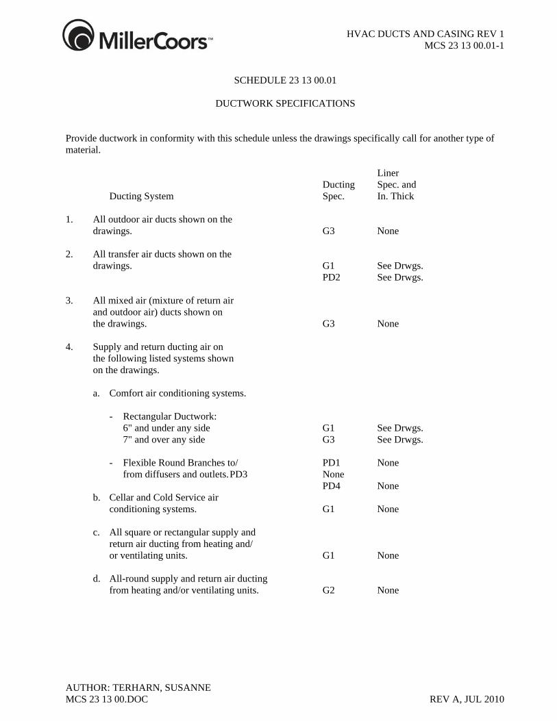
DUCTWORK SPECIFICATIONS
Provide ductwork in conformity with this schedule unless the drawings specifically call for another type of material. Liner Ducting Spec. and Ducting System Spec. In. Thick 1. All outdoor air ducts shown on the drawings. G3 None 2. All transfer air ducts shown on the drawings. G1 See Drwgs. PD2 See Drwgs. 3. All mixed air (mixture of return air and outdoor air) ducts shown on the drawings. G3 None 4. Supply and return ducting air on the following listed systems shown on the drawings. a. Comfort air conditioning systems. - Rectangular Ductwork: 6" and under any side G1 See Drwgs. 7" and over any side G3 See Drwgs. - Flexible Round Branches to/ PD1 None from diffusers and outlets. PD3 None PD4 None b. Cellar and Cold Service air conditioning systems. G1 None c. All square or rectangular supply and return air ducting from heating and/ or ventilating units. G1 None d. All-round supply and return air ducting from heating and/or ventilating units. G2 None
MCS 23 13 00.DOC REV A, JUL 2010
HVAC DUCTS AND CASING REV 1 MCS 23 13 00.01-2
AUTHOR: TERHARN, SUSANNE MCS 23 13 00.DOC REV A, JUL 2010
SCHEDULE 23 13 00.01
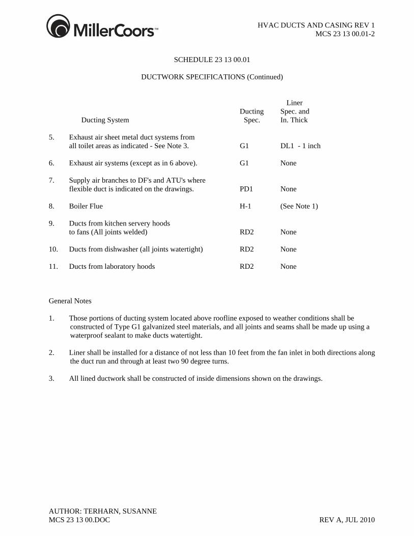
DUCTWORK SPECIFICATIONS (Continued)
Liner Ducting Spec. and Ducting System Spec. In. Thick 5. Exhaust air sheet metal duct systems from all toilet areas as indicated - See Note 3. G1 DL1 - 1 inch 6. Exhaust air systems (except as in 6 above). G1 None 7. Supply air branches to DF's and ATU's where flexible duct is indicated on the drawings. PD1 None 8. Boiler Flue H-1 (See Note 1) 9. Ducts from kitchen servery hoods to fans (All joints welded) RD2 None 10. Ducts from dishwasher (all joints watertight) RD2 None 11. Ducts from laboratory hoods RD2 None General Notes 1. Those portions of ducting system located above roofline exposed to weather conditions shall be
constructed of Type G1 galvanized steel materials, and all joints and seams shall be made up using a waterproof sealant to make ducts watertight.
2. Liner shall be installed for a distance of not less than 10 feet from the fan inlet in both directions along
the duct run and through at least two 90 degree turns. 3. All lined ductwork shall be constructed of inside dimensions shown on the drawings.
HVAC DUCTS AND CASING REV 1 MCS 23 13 00.01.G1-1
AUTHOR: TERHARN, SUSANNE
DUCTWORK SPECIFICATION G1 Sheets: ASTM A653/A653M galvanized steel sheets, lock forming quality, having G90 zinc
coating in conformance with ASTM A90/A90M Structurals: Phosphatized, galvanized steel, ASTM A36, ASTM A123. Bars: Phosphatized, galvanized steel, ASTM A575, ASTM, A123. Strip: Phosphatized, galvanized steel, ASTM A653 Rods: Hot-rolled steel, bare, ASTM A575. Construction: Thickness and Reinforcement :In accordance with ASHRAE/SMACNA Duct
Construction Standards Metal and Flexible. Seams of all ductwork shall be sealed in accordance with Seal Class A of the SMACNA-HVAC Duct Construction Standards Metal and Flexible latest edition. All sealants used shall be waterproof and ultraviolet ray resistant.
Exhaust and return ducts sealed in accordance with Seal Class B.
MCS 23 13 00.DOC REV A, JUL 2010
11 HVAC DUCTS AND CASING REV 1 MCS 23 13 00.01.G2-1
AUTHOR: TERHARN, SUSANNE
DUCTWORK SPECIFICATION G2
Sheets: ASTM A653/A653M galvanized steel sheets, lock forming quality, having G90 zinc
coating in conformance with ASTM Structurals: Phosphatized, galvanized steel, ASTM A36, ASTM A123. Bars: Phosphatized, galvanized steel, ASTM A575, ASTM A123. Strip: Phosphatized, galvanized steel, ASTM A653 ASTM A123. Rod: Hot-rolled steel, ASTM A575. Duct Construction: Spiral Lockseam, as manufactured by United McGill Corp. or SteelCraft. Fittings: Factory fabricated with continuous welds along all seams. 90° tees and 45° wyes
12" and smaller shall have a radius-type entrance into the tap produced by machine or press forming. Elbows 8" and smaller shall be two section, die-stamped. Larger elbows shall be gored construction with all seams continuous, welded and fabricated in accordance with the following schedule:
Elbow Angle Number of Gores Angles less than 35 Not Allowed 35° 2 36 through 71° 3 Over 71° 5 Painting: In exposed areas, where painting is required, exterior surfaces must be cleaned to
remove oils and factory primer applied.
MCS 23 13 00.DOC REV A, JUL 2010
11 HVAC DUCTS AND CASING REV 1 MCS 23 13 00.01.G3-1
AUTHOR: TERHARN, SUSANNE
DUCTWORK SPECIFICATION G3 Sheets: ASTM A653/A653M galvanized steel sheets, lock forming quality, having G90 zinc
coating in conformance with ASTM A90/A90M. Structurals: Phosphatized, galvanized steel, ASTM A36, ASTM A 123. Bars, Rods: Phosphatized, galvanized steel. ASTM A575 ASTM 123. Construction: In accordance with ASHRAE/SMACNA duct construction standards and the
traverse joints of the Ductmate System. All longitudinal seams shall be sealed in accordance with Class A SMACNA-HVAC
Duct Construction Standards of the latest edition. All sealants to be waterproof and ultraviolet ray resistant.
MCS 23 13 00.DOC REV A, JUL 2010
11 HVAC DUCTS AND CASING REV 1 MCS 23 13 00.01.H1-1
AUTHOR: TERHARN, SUSANNE
DUCTWORK SPECIFICATION H1 Material: Sizes 10" through 36" inside diameter. Factory-constructed pipe, fittings, and
accessories of double-wall construction having a minimum air space between the inner and outer wall of one-inch. Inner-wall construction, stainless steel. Outer wall construction, aluminized steel.
Joints: Straight pipe, fittings, and accessories shall employ factory-constructed coupling
devices fitted to each end for joining. All joints shall be secured with internal V bands and external channel bands. For flue gas temperatures up to 600° use RTV Sealant P-600; for flue gas temperatures above 600°F and below 1400°F use Sauereisen No. 33 Joint Cement P-1400.
Accessories: Ducting systems shall be made up with the appropriate use of factory-constructed
fittings and accessories including tees, caps, elbows, increasers, reducers, storm collars, roof flashings, thimbles, bracings, supports, expansion joints, insulated exit cone or stack cap, and condensation drains.
Approval: Ducting system shall be Underwriters' Laboratories Listed for oil-fired heating
equipment vents. Manufacturer: Selkirk Metalbestos "Model PS".
MCS 23 13 00.DOC REV A, JUL 2010
11 HVAC DUCTS AND CASING REV 1 MCS 23 13 00.01.PD1-1
AUTHOR: TERHARN, SUSANNE
DUCTWORK SPECIFICATION PD1
Description: Flexible low-pressure duct for air conditioning and heating, consisting of corrosion
resistant reinforcing wire helix permanently bonded and enclosed in polyester film, one-inch-thick fiberglass insulation of 3/4 pound per cubic foot density and sheathed with seamless vinyl vapor barrier.
Accessories: Spin-in collar with damper, if required or indicated. Application: Suitable for air velocities up to 4000 fpm, pressures up to 6 in. W.G. and
temperatures from -20°F to 250°F. Approvals: Duct shall be UL listed and labeled, and shall comply with NFPA Bulletin 90A
/90B. Manufacturers: Duct shall be, Flexmaster FAB 5T or approved equal.
MCS 23 13 00.DOC REV A, JUL 2010
11 HVAC DUCTS AND CASING REV 1 MCS 23 13 00.01.PD2-1
AUTHOR: TERHARN, SUSANNE
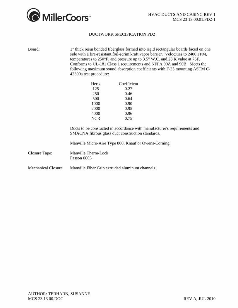
DUCTWORK SPECIFICATION PD2
Board: 1" thick resin bonded fiberglass formed into rigid rectangular boards faced on one
side with a fire-resistant,foil-scrim kraft vapor barrier. Velocities to 2400 FPM, temperatures to 250°F, and pressure up to 3.5" W.C. and.23 K value at 75F. Conforms to UL-181 Class 1 requirements and NFPA 90A and 90B. Meets the following maximum sound absorption coefficients with F-25 mounting ASTM C-42390a test procedure:
Hertz Coefficient 125 0.27 250 0.46 500 0.64 1000 0.90 2000 0.95 4000 0.96 NCR 0.75 Ducts to be constucted in accordance with manufacturer's requirements and
SMACNA fibrous glass duct construction standards. Manville Micro-Aire Type 800, Knauf or Owens-Corning. Closure Tape: Manville Therm-Lock Fasson 0805 Mechanical Closure: Manville Fiber Grip extruded aluminum channels.
MCS 23 13 00.DOC REV A, JUL 2010
11 HVAC DUCTS AND CASING REV 1 MCS 23 13 00.01.PD3-1
AUTHOR: TERHARN, SUSANNE
DUCTWORK SPECIFICATION PD3
Description: Flexible low pressure duct constructed of a wire reinforced trilaminate liner of
aluminum foil fiberglass and aluminized polyester. The wire is a .3" wire, 24 ga. aluminum Helix spiral mechanically locked to the fabric liner, 1" spacing between Helix. The duct shall be wrapped in a fiberglass insulation jacket and encased in a outer jacket of fire-retardant polyethlylene film.
Approvals: Duct shall be UL listed 181 Class 1 air duct material and comply with NFPA 90A
and 90B. Application: Suitable for velocities to 4000 fpm, pressure to 12" W.C. and temperatures from -20
F to +250F. Manufacturers: As manufactured by Flexmaster, Fab-3T or approved equal.
MCS 23 13 00.DOC REV A, JUL 2010
11 HVAC DUCTS AND CASING REV 1 MCS 23 13 00.01.PD4-1
AUTHOR: TERHARN, SUSANNE
DUCTWORK SPECIFICATION PD4
Description Flexible low pressure duct constructed of a wire reinforced trilaminate liner of
aluminum foil fiberglass and aluminized polyester. The wire is a .3"wire, 24 ga. aluminum Helix spiral mechanically locked to the fabric liner. 1-1/2" spacing between Helix. The duct shall be wrapped in a fiberglass insulation jacket and encased in a outer jacket of fire-retardant reinforced metalized outer jacket.
Approvals: Duct shall be UL listed, Class 1 air duct material and comply with NFPA 90A and
90B. Application: Suitable for air velocities to 4,000 fpm, pressures up to 12" W.C. and temperatues
from -20F to +250. Manufacturer: As manufactured by Flexmaster, Fab-3M, or approved equal.
MCS 23 13 00.DOC REV A, JUL 2010
11 HVAC DUCTS AND CASING REV 1 MCS 23 13 00.01.RD2-1
AUTHOR: TERHARN, SUSANNE
DUCTWORK SPECIFICATION RD2
Materials: ASTM A240 Cold Rolled Nickel-Chrome stainless steel sheets type 304 304L,
316/316L 2D finish. Structurals: Those in contact with duct surfaces Type 304 stainless steel. Bars: Cold-rolled nickel-chrome stainless steel type 304. Strip: Same as Sheet. Rod: Type 304 stainless. Fasteners / Bolts F593-Gr.2-A Type 304 stainless. Construction: In accordance with SMACNA duct construction standards and the Traverse Joints of
the Ductmate Stainless Steel System. All materials type 304 stainless steel. Use Class "A" seals per SMACNA Duct Construction Standards. In concealed location use minimum 18 gauge with all joints welded liquid tight and ground smooth . In exposed location use 18 gauge or heavier with nimber 3 finish with all joints welded liquid tight. Grind and polish all welded joints and seams to a number 3 finish. No turning vanes may be used in kitchen , dishwasher , and laboratory exhaust ducts. Use 304L stainless steel for kitchen and dishwasher exhaust ducts. Use 316L stanless steel for laboratory exhaust duct. Kitchen exhaust shall be wrapped with 1-1/2” thick fire wrap, double wrapped, K=0.46 Btu-in/(hr-ft-˚F) at 500˚F. Fire wrap shall have a 2 hour fire rating. Approved manufacturer is Thermal Ceramics Firemastic.
MCS 23 13 00.DOC REV A, JUL 2010
11 HVAC DUCTS AND CASING REV 1 MCS 23 13 00.01.DL1-1
AUTHOR: TERHARN, SUSANNE
DUCT LINER SPECIFICATION DL1
Material: Bonded mat of glass fiber-coated with a black pigmented fire-resistive coating on
the air stream side. Thickness as scheduled in Table 15D-1. Suitable for sound absorption and thermal insulation, air velocities to 6000 FPM, and to be applied to the interior of ductwork.
Density: 1.5 lb. cubic foot. Approval: Shall meet requirements of NFPA90 with a flame spread rating of 25 and smoke
developed rating of 50 when tested in accordance with ASTM E84. Conductance: Average thermal conductivity not to exceed .26 BTU-In/Sq. Ft/°F Hour at a mean
temperature of 75°F. Manufacturer: Owens-Corning Fiberglass "Aeroflex"; Mansville "Linacoustic"; Certainteed
"Ultralite"; or Knauf. Installation: Use mechanical fasteners and adhesive coverage as recommended by manufacturers.
MCS 23 13 00.DOC REV A, JUL 2010
11 HVAC DUCTS AND CASING REV 1 MCS 23 13 00.01.DL2-1
AUTHOR: TERHARN, SUSANNE
DUCT LINER SPECIFICATION DL2 Material: Insulation shall be AP/Armaflex sheet insulation, supplied as flat sheets, flexible
elastomeric insulation, black, in color. Approval: Shall meet requirements of NFPA 90 with flame spread of 25 and smoke developed
rating of 50 when tested in accordance with ASTM E84. Conductance: Average thermal conductivity not to exceed .27 BTU-in/Sq. Ft. °F Hour at a mean
temperature of 75°F. Installation: Apply sheets of AP/Armaflex insulation in one or two layers, as required by the
thickness specified. Use manufacturer's recommended adhesive. Apply a brush coat of adhesive to the backside of the insulation, leaving 1/2 inch along each edge uncoated, and to the surface to be insulated. The surface to be insulated must be clean, dry and free of dirt and scale. Position sheets so that each sheet overlaps adjacent sheets by 1/8 inch. Spot adhere the center of the sheet, then press the butt edges into place to achieve a tight joint. Bond the remainder of the sheet by pressing firmly into place. Spread the butt joint and apply adhesive with a small brush to both ends and apply pressure to joint. Where the insulation is applied in two layers, stagger the joints in the two different layers.
Finish: No finish is required on Armaflex duct lining.
MCS 23 13 00.DOC REV A, JUL 2010
11 HVAC DUCTS AND CASING REV 1 MCS 23 13 00.02-1
AUTHOR: TERHARN, SUSANNE
SCHEDULE 23 13 00.02 TYPICAL EQUIPMENT
Provide equipment in conformity with this schedule unless the HVAC drawings specifically call for another type of equipment. Description Type Access Door for duct openings. AD See plans for sizes. Backdraft Dampers Fabric Blade BDD1 Low Velocity Systems BDD2 Medium Velocity Systems BDD3 Diffusers DF1 through DF8 Fire Damper FDP1 through FDP4 Flexible Connection Indoors FLX1 Outdoors FLX2 Fixed Weatherproof Louver Extruded Aluminum FWL1 Galvanized FWL2 Grilles GR1 through GR11 Hoods Intake HD1 Relief or Exhaust HD2 Hand-Operated Weatherproof Louver Aluminum HWL1 Galvanized HWL2 Pressure Differential Indicator PDI1 through PDI3 Registers RG1 through RG8 Splitter Damper SD1 Volume Damper VDP1 VDP2 Plenum Access Doors PAD as detailed on Drawings
MCS 23 13 00.DOC REV A, JUL 2010
11 HVAC DUCTS AND CASING REV 1 MCS 23 13 00.02.AD-1
AUTHOR: TERHARN, SUSANNE
DUCTWORK EQUIPMENT SPECIFICATION
AD ACCESS DOOR
Type Description AD Duct access doors for access to duct sensors, auto dampers, backdraft dampers, fire
dampers, and where shown. Standard construction for up to 4.5” satic pressure as manufactured by CESCO, Inc., HDD100 or HDD101 Ventlok or equal, of sizes shown and required. Provide Ventlok No. 200 door latches for doors 8 square feet in area or less and No. 300 for doors larger.
Plenum Access Doors; for access to built-up Plenums will be specified with the
Plenum specifications.
MCS 23 13 00.DOC REV A, JUL 2010
11 HVAC DUCTS AND CASING REV 1 MCS 23 13 00.02.BDD-1
AUTHOR: TERHARN, SUSANNE
DUCTWORK EQUIPMENT SPECIFICATION
BDD BACKDRAFT DAMPER Type Description BDD1 For installation in ductwork; 18 gauge galvanized steel frame, double-coated
neoprene fabric blades in a 4" wide frame. Use for velocities less than 1,000 fpm.. Vent Products 3600 American Warming and Ventilating, Inc. Louvers and Dampers, Inc. Ruskin Mfg. Co. BDD2 BACKDRAFT DAMPER: For installation in ductwork. 14 gauge press-formed
galvanized steel frame, .08 aluminum blades with "V" formed reinforcements, 1/2" corrosion-resistant shafts and 1/2" dia. ball bearings, blades linked to operate in unison, elastomeric seals for blade edges, and counterbalanced, welded frames and riveted hardware, standard mill finish. Suitable for installation in a vertical plane, for horizontal air flow for low velocity low pressure systems.
Vent Products Model 3100 American Warming and Ventilating, Inc. Louvers & Dampers, Inc. Ruskin Mfg. Co. BDD3 BACKDRAFT DAMPER: For installation in ductwork. 12 gauge galvanized steel
frame with flange, 16 gauge galvanized steel blades with "V" formed reinforcements 1/2" dia. corrosion-resistant shafts and 1/2" ball bearings, blades linked to operate in unison, elastomeric seals for blade edges, and counterbalanced, welded frames and riveted hardware, standard mill finish. Suitable for installation in a vertical plane for horizontal air flow for medium velocity, medium pressure systems.
Vent Products, Model 3200 American Warming and Ventilating Louvers & Dampers, Inc. Ruskin Mfg. Co.
MCS 23 13 00.DOC REV A, JUL 2010
11 HVAC DUCTS AND CASING REV 1 MCS 23 13 00.02.DF-1
AUTHOR: TERHARN, SUSANNE
DUCTWORK EQUIPMENT SPECIFICATION
DF DIFFUSER Type Description DF1 CEILING DIFFUSER: Square or rectangular aluminum diffuser with removable
core and flat overlap margin for exposed duct installation or ceiling installation with other than a suspended grid ceiling; with control grid and opposed blade damper key operated through face; satin aluminum etch finish with acrylic plastic coat.
DAMPER: Carnes Model KXKAS or approved equal. Not required if damper in duct. DIFFUSER: Carnes Model SAFM or approved equal. DF2 DIFFUSER: Square or rectangular aluminum diffuser with removable core; with
control grid and opposed blade damper key-operated through face; for suspended grid ceiling; nominal modular panel sizes as indicated on Architectural Drawings; exact panel size and edge design to suit ceiling system furnished; baked white enamel finish.
DAMPER: Carnes Model KXKAS or approved equal. Not required if damper in duct. DIFFUSER: Carnes Model SAFM or approved equal.
MCS 23 13 00.DOC REV A, JUL 2010
11 HVAC DUCTS AND CASING REV 1 MCS 23 13 00.02.DF-2
AUTHOR: TERHARN, SUSANNE
DUCTWORK EQUIPMENT SPECIFICATION
DF DIFFUSER (Continued) Type Description DF3 DIFFUSER: Round, steel, fully adjustable with removable core and flat overlap
margin for exposed duct installation or ceiling installation with other than a suspended grid ceiling; with baked white enamel finish.
DAMPER: Carnes Model KXRA or approved equal. DIFFUSER: Carnes Model SSAA-1 or approved equal. DF4 DIFFUSER: Removable core; four-way blow; overlapping margin for ceiling or
exposed duct installation; baked enamel finish to match ceiling system; steel with baked white enamel finish.
Titus MCD or approved equal. DF5 DIFFUSER: Removable core; one-, two-three-, or four-way blow as indicated on
the drawings; pattern as required to suit space; for suspended grid ceiling; in nominal modular panel sizes as indicated on Architectural Drawings; exact panel size and edge design to suit ceiling system furnished, baked enamel finish to match ceiling; steel or aluminum (Normally furnished in steel.).
Titus MCD or approved equal.
MCS 23 13 00.DOC REV A, JUL 2010
11 HVAC DUCTS AND CASING REV 1 MCS 23 13 00.02.DF-3
AUTHOR: TERHARN, SUSANNE MCS 23 13 00.DOC REV A, JUL 2010
DUCTWORK EQUIPMENT SPECIFICATION
DF DIFFUSER Type Description DF-6 Linear, slotted, with adjustable air directional blades to obtain desired discharge
pattern; for installation in T-bar ceiling grid. Diffuser to include minimum 26 gauge zinc coated steel plenum with duct collar, factory applied enamel finish and diffuser section finished to match the ceiling grid. Interior surfaces shall be acoustically and thermally insulated with glass fiber, surface treated to prevent erosion. Insulation materials shall meet NFPA No. 90A standards.
Carnes Model, DARC , Trane or approved equal. See plans for sizes and number of slots.
DF-7 Linear, slotted, for return air with 22 gauge minimum zinc coated steel plenum plenum and diffuser section finished to match ceiling grid. Carnes Model, DAVC , Trane or approved equal. See plans for size and number of slots. DF-8 T-bar ceiling type, slotted linear diffuser for horizontal air flow. Slot edges formed
over for double thickness with exposed surfaces finished with white enamel. Provide minimum 26 gauge zinc coated plenum with duct collar and the interior is to be lined with 1/2" thick, 1-1/2 lb. density fiberglass insulation. Insulation to be coated to prevent erosion, be UL listed, and meet NFPA 90A / 90B requirements.
Carnes, DFSB, Trane, or approved equal: See plans for sizes and number of slots.
11 HVAC DUCTS AND CASING REV 1 MCS 23 13 00.02.FDP-1
AUTHOR: TERHARN, SUSANNE
DUCTWORK EQUIPMENT SPECIFICATION
FDP FIRE DAMPER Type Description FDP1 FIRE DAMPERS: Fire dampers shall be complete with (spring catches for
horizontal mounting) and installed in compliance with NFPA Bulletin No. 90A. Fusible links shall be set for operation at 165°F. Fire dampers shall be curtain-type with interlocking blades, UL Type B, and blade compartment out of airstream. 1-1/2 hour fire rating.
Air Balance Inc., Model 119BLH Prefco Model E4-BC Ruskin Mfg. Co., Model IBD2 FDP2 FIRE DAMPERS: For installation to protect openings in fire walls through which
ducts pass. Dampers shall be constructed in accordance with NFPA Bulletin No. 90A. Fire dampers shall be of the trap-door-type suitable for installation in either horizontal or vertical ducts. Damper blade shall have a three hour rating and shall be identified with a UL label. The blade compartment shall be out of the airstream. Fusible link shall be designed for operation at 160°F.
Air Balance Inc., Model 119B Prefco Model E4-BC
FDP3 FIRE DAMPERS: For installation to protect openings in fire walls or openings
through which ducts pass. Dampers shall be constructed in accordance with NFPA Bulletin No. 90A. Fire dampers shall be of the guillotine-type suitable for installation in a vertical wall. Damper blade shall have a 3 hour rating and shall be identified with a UL label. The blade compartment shall be out of the airstream. Fusible link shall be designed for operation at 160°F.
Air Balance Inc., Model 319B Ruskin Manufacturing Company, IBD23.
MCS 23 13 00.DOC REV A, JUL 2010
11 HVAC DUCTS AND CASING REV 1 MCS 23 13 00.02.FDP-2
AUTHOR: TERHARN, SUSANNE MCS 23 13 00.DOC REV A, JUL 2010
DUCTWORK EQUIPMENT SPECIFICATION
FDP FIRE DAMPER (continued) Type Mfg. Co., Model IBD2 Type CR. Description FDP4 FIRE DAMPERS: For installation in round ducts passing through a Fire partition in
the vertical or horizontal plane. Complete with spring catches when horizontally mounted and installed in compliance with NFPA-90A. Fusible links shall be set for operation at 165°F. Fire dampers shall have rectangular damper housing with standard male fittings for round ducts. Dampers shall be curtain-type with interlocking blades, UL Type B label onblades. Blade compartment shall be out of airstream. 1-1/2 hour fire rating.
Prefco Model E4-CR Ruskin Air Balance Inc., Model 119CLH
11 HVAC DUCTS AND CASING REV 1 MCS 23 13 00.02.FLX-1
AUTHOR: TERHARN, SUSANNE
DUCTWORK EQUIPMENT SPECIFICATION
FLX FLEXIBLE DUCT CONNECTION Type Description FLX1 FLEXIBLE DUCT CONNECTION: Indoor Equipment Non-Corrosive Air Sytems
Glass fabric, 30 ounce per square yard, tightly woven, double-coated with Neoprene, fire-retardant, waterproof, airtight, for service temperature -40˚ up to 200°F , and classified by the Underwriters' Laboratories UL 214. and shall conform to NFPA Standard No. 90A/90B.
Ventfabrics Ventglas, or approved equal. FLX2 FLEXIBLE DUCT CONNECTION: Outdoor Equipment Non-Corrosive Air
Sytems (Exposed to Weather and Sun): Coated-glass fabric, double-coated with Hypalon, resistant to sunlight, ozone and weathe 24-26 ounces per square yard, noncombustible fabric, fire-retardant coating. For service temperature at -40˚F up to 250°F . Material shall comply with U.S. Standard 214, and shall conform to NFPA Standard No. 90A/90B .
Ventfabrics Ventlon Duro Dyne Durlon or approved equal
MCS 23 13 00.DOC REV A, JUL 2010
11 HVAC DUCTS AND CASING REV 1 MCS 23 13 00.02.FWL-1
AUTHOR: TERHARN, SUSANNE
DUCTWORK EQUIPMENT SPECIFICATION
FWL FIXED WEATHERPROOF LOUVER Type Description FWLl LOUVER: Extruded aluminum, 6-inches deep with blades on 3-1/2 inch centers and
channel or flanged frame. Blades shall have two reinforcing V's, or the equivalent, and integral downspouts to drain water from them. Blades and frame shall be constructed of 6063-T5 alloy not lighter than 0.081-inch thick. A bird screen shall be installed on the interior side and have extruded aluminum "U" frame with 1/2" mesh 0.063" diameter aluminum wire.
Performance: When based on a 48-inch-square sample and tested in accordance with AMCA Standard 500, louver shall pass 1100 fpm free air velocity with less than 0.2 inches of water gauge pressure drop and shall carry less than 0.03 ounces of water per square foot during a 15-minute period.
Louver shall bear the AMCA Certified Ratings seal for both Air Performance and Water Penetration.
Louver shall have a clear anodized finish.
American Warming and Ventilating Model LE-31, Dowco DBE-6, Vent Products
2850, Louvers & Dampers, Inc. Model IEL-67.
MCS 23 13 00.DOC REV A, JUL 2010
11 HVAC DUCTS AND CASING REV 1 MCS 23 13 00.02.FWL-2
AUTHOR: TERHARN, SUSANNE MCS 23 13 00.DOC REV A, JUL 2010
DUCTWORK EQUIPMENT SPECIFICATION
FWL FIXED WEATHERPROOF LOUVER Type Description FWL2 LOUVER: Galvanized steel, 6-inches deep with blades on 3-1/2 inch centers and
channel frame. Blades shall have two reinforcing V's, or the equivalent, and integral downspouts to drain water from them. Blades shall be 20 gauge and frames shall be 16 gauge. A bird screen shall be installed on the interior side and have a galvanized "U" frame with 1/2" mesh 0.041" diameter galvanized wire.
Performance: Performance, when based on a 48-inch-square sample and tested in accordance with AMCA Standard 500, shall pass approximately 1100 fpm free air velocity with less than 0.2 inches of water gauge pressure drop and shall carry less than 0.07 ounces of water per square foot during a 15-minute period.
Louver shall bear the AMCA Certified Ratings seal for both Air Performance and Water Penetration.
American Warming and Ventilating Model L F-31 Dowco DBF-06 or Vent Products, Model 4650 Louvers & Dampers, Inc. Model IEL-67 .
11 HVAC DUCTS AND CASING REV 1 MCS 23 13 00.02.GR-1
AUTHOR: TERHARN, SUSANNE
DUCTWORK EQUIPMENT SPECIFICATION
GR GRILLE Type Description GR1 GRILLE: Supply, square or rectangular aluminum grille; 1-1/4" wide margin with
pierced screw holes, mounting screws and gasket; double-deflection type with horizontal face bars and vertical rear bars; grille bars of extruded aluminum 1-1/2" deep on 1-1/2" centers individually adjustable and friction loaded to hold deflection setting; minimum free area 90 percent; etched and acrylic coat finish on face.
Carnes Model RAFAH or approved equal. GR2 GRILLE: Return, ceiling or sidewall application, square or rectangular aluminum
grille; 1-1/4" wide margin with pierced screw holes, mounting screws and gasket; fixed horizontal bars with 0° straight deflection; grille bars of extruded aluminum, streamlined, on 3/4" centers; minimum free area 75 percent; etched and acrylic coat finish on face.
Carnes Model RARAH or approved equal. GR3 GRILLE: Return or exhaust; square or rectangular; grid core, 1/2" x 1/2" x 1/2"; 1-
1/4" margin; extruded aluminum, etched and acrylic coat finish. Carnes Model RAPAF or approved equal. GR4 GRILLE: Wall transfer; fixed fin removable core; l-inch fixed frame; electro-plated
zinc finish; steel. Carnes Model RSLAH or approved equal. GR5 GRILLE: Supply, spiral duct air distributor with perforated outlets having a 45° air
pattern, and a rotating damper. United Sheet Metal Duct-D-fuser Type AD or approved equal.
MCS 23 13 00.DOC REV A, JUL 2010
11 HVAC DUCTS AND CASING REV 1 MCS 23 13 00.02.GR-2
AUTHOR: TERHARN, SUSANNE
DUCTWORK EQUIPMENT SPECIFICATION
GR GRILLE Type Description GR6 GRILLE: Return, same as GR2 except with fixed horizontal bars at 40° face
deflection. Carnes Model RAAAH
or approved equal. GR7 GRILLE: Supply, square or rectangular aluminum grille; 1-1/4" wide margin with
pierced screw holes, mounting screws and gasket; double deflection type with horizontal face bars and vertical rear bars; grille bars of extruded aluminum on 3/4" centers individually adjustable and friction loaded to hold deflection setting; minimum free area 80 percent; etched and acrylic coat finish on face.
Carnes Model RWDAH or approved equal. GR8 GRILLE: Supply, same as GR7 except with vertical face bars and horizontal rear
bars. Carnes Model RWDAV or approved equal.
MCS 23 13 00.DOC REV A, JUL 2010
11 HVAC DUCTS AND CASING REV 1 MCS 23 13 00.02.GR-3
AUTHOR: TERHARN, SUSANNE MCS 23 13 00.DOC REV A, JUL 2010
DUCTWORK EQUIPMENT SPECIFICATION
GR GRILLE Type Description GRa GRILLE: Return or exhaust; square or rectangular; for tee-bar suspended grid
ceiling; nominal modular panel sizes as indicated on Drawings; exact size to suit ceiling system furnished; 1/2" x 1/2" x 1/2" grid core; etched finish; aluminum.
Carnes Model RAPAH or approved equal. GR10 GRILLE: Return or exhaust; square or rectangular; for lay-on tee-bar-type
suspended grid ceiling; nominal modular panel sizes as indicated on Architectural Drawings; exact size to suit ceiling system furnished; 1" x 1" x 1" grid core; etched finish; aluminum.
Carnes RAEAF or approved equal. GR13 Return or exhaust grilles - square or rectangular type complete with horizontal fixed
curve face bars on 3/4" centers, and frame with 1-1/4" bevelled border. All steel construction with a temperature set white paint finish.
Carnes RSLAH or approved equal.
11 HVAC DUCTS AND CASING REV 1 MCS 23 13 00.02.HD-1
AUTHOR: TERHARN, SUSANNE
DUCTWORK EQUIPMENT SPECIFICATION
HD HOOD Type Description HD1 AIR INTAKE HOOD: The intake hoods shall be roof-mounted-type, designed for
installation on curb, and complete with bird screens.
Units shall be capable of meeting the design requirements set forth herein. Capacity of units shall be based on a maximum intake velocity of 500 fpm across the horizontal hood intake plane. Free area of intake to be not less than Ft.2 free area of inside duct throat area.
Housings: Base shall be fabricated of 16 gauge galvanized steel; hood to be fabricated from 20 gauge galvanized steel. Entire assembly shall be suitably reinforced with stiffeners and/or angles. All hood seams shall be lock-formed at the ends; all vertical seams to be continuously welded.
Bird Screen: Bird screen shall be 1/2" x 1/2" mesh 0.063" galvanized wire cloth. Screen shall be framed for removal and/or cleaning.
Vendor List Penn Ventilator Company - (Airette Type Intake) Greenheck Fan & Ventilator Corp. - (Type GIH) Louvers and Dampers, Inc. Model SGV Carnes Model GI
MCS 23 13 00.DOC REV A, JUL 2010
11 HVAC DUCTS AND CASING REV 1 MCS 23 13 00.02.HD-2
AUTHOR: TERHARN, SUSANNE MCS 23 13 00.DOC REV A, JUL 2010
DUCTWORK EQUIPMENT SPECIFICATION
HD HOOD (Continued) Type Description HD2 AIR RELIEF OR EXHAUST HOOD: The hoods shall be roof-mounted-type
designed for installation on curbs and complete with bird screens.
Units shall be capable of meeting the design requirements set forth herein.
Housings: Base shall be fabricated of 16 gauge galvanized steel; hood to be fabricated from 20 gauge galvanized steel. Entire assembly shall be suitably reinforced with stiffeners and/or angles. All hood seams shall be lock-formed at the ends; all vertical seams shall be continuously welded.
Bird Screen: Bird screen shall be 1/2" x 1/2" mesh 0.063" galvanized wire cloth. Screen shall be framed for removal and/or cleaning.
Relief Damper: Pressure relief damper: See backdraft dampers (BDD).
Vendor List Penn Ventilator Company - (Airette Type - Relief) Greenheck Fan & Ventilator Corp. - (Type GIH) Louvers and Dampers, Inc. Model SGV Carnes Model GE
11 HVAC DUCTS AND CASING REV 1 MCS 23 13 00.02.HWL-1
AUTHOR: TERHARN, SUSANNE
DUCTWORK EQUIPMENT SPECIFICATION
HWL HAND-OPERATED WEATHERPROOF LOUVER Type Description HWL1 Extruded aluminum louver 6-inches deep with blades on 3-1/2 centers and channel
frame. Blades shall have two reinforcing V's or the equivalent, and integral downspouts to drain water from them. Blades and frame shall be constructed of 6063-T5 alloy not lighter than 0.081-inch thick. A bird screen shall be installed on the exterior side and have extruded aluminum "U" frame with 1/2" mesh 0.063" diameter aluminum wire.
Performance: Performance shall approach that of a fixed louver of similar design which, when based on a 48-inch-square sample and tested in accordance with AMCA Standard 500, shall pass 1100 fpm free air velocity with less than 0.2 inches of water gauge pressure drop and shall carry less than 0.03 ounces of water per square foot during a 15-minute period.
Louver shall bear the AMCA Certified Ratings seal for both Air Performance and Water Penetration.
Louver shall have a clear anodized finish.
Operator:
Sill 7 ft. maximum above floor: wing-nut type. Sill more than 7 ft. above floor: chain type.
American Warming and Ventilating Model LE-31A or Vent Products
MCS 23 13 00.DOC REV A, JUL 2010
11 HVAC DUCTS AND CASING REV 1 MCS 23 13 00.02.HWL-2
AUTHOR: TERHARN, SUSANNE MCS 23 13 00.DOC REV A, JUL 2010
DUCTWORK EQUIPMENT SPECIFICATION
HWL HAND-OPERATED WEATHERPROOF LOUVER Type Description HWL2 Galvanized steel louver 6-inches deep with blades on 3-1/2 inch centers and channel
frame. Blades shall have two rein- forcing V's or the equivalent, and integral downspouts to drain water from them. Blades and frame shall be constructed of 6063-T5 alloy not lighter than 0.041-inch thick. A bird screen shall be installed on the exterior side and have a galvanized "U" frame with 1/2" mesh 0.041" diameter galvanized wire. Axles, linkage, and blade brackets shall be plated steel. Bearings shall be heavy-duty molded nylon.
Performance: Performance shall approach that of a fixed louver of similar design which, when based on a 48-inch-square sample and tested in accordance with AMCA Standard 500, shall pass 1100 fpm free air velocity with less than 0.2 inches of water gauge pressure drop and shall carry less than 0.03 ounces of water per square foot during a 15-minute period.
Louver shall bear the AMCA Certified Ratings seal for both Air Performance and Water Penetration.
Operator:
Sill 7 ft. maximum above floor: wing-nut type. Sill more than 7 ft. above floor: chain type. American Warming and Ventilating Model L F -31A or Vent Products.
11 HVAC DUCTS AND CASING REV 1 MCS 23 13 00.02.PDI-1
AUTHOR: TERHARN, SUSANNE
DUCTWORK EQUIPMENT SPECIFICATION
PDI PRESSURE DIFFERENTIAL INDICATOR
Type Description PRESSURE DIFFERENTIAL INDICATOR: Pressure indicator shall be direct-
reading dial-type with a range as indicated below in inches of water column. The indicator shall be diaphragm actuated with 4" diameter dial, and pointer zero adjustment. Fittings for connection to tubing shall be included. A-310A vent valves, adjustable signal flag and air filter gage accuracy package for all filter applications. Manufactured "Pilot Tube" type static and velocity pressure tips must be used.
Indicators shall be: PDI1 Dwyer Model No. 2001AF, 0-1" W.C. PDI2 Dwyer Model No. 2002AF, 0-2" W.C. PDI3 Dwyer Model No. 2005AF, 0-5" W.C.
MCS 23 13 00.DOC REV A, JUL 2010
11 HVAC DUCTS AND CASING REV 1 MCS 23 13 00.02.RG-1
AUTHOR: TERHARN, SUSANNE
DUCTWORK EQUIPMENT SPECIFICATION
RG REGISTER
Type Description RG1 REGISTER: Supply, for sidewall application on exposed duct work; square or
rectangular; 1-1/4" wide border; screwmounted; horizontal and vertical pattern adjustment; horizontal face bars; extruded aluminum construction with etched and acrylic coat finish.
Carnes, RASAH, 3/4 inch blade spacing, single deflection . or approved equal.
RG2 REGISTER: Return or exhaust; ceiling or sidewall application; square or
rectangular; 1-1/4" wide gasketed border; fixed horizontal extruded aluminum face bars on 3/4" centers and 45 degree deflection; aluminum with etched and acrylic coat finish.
Carnes RWAAH or approved equal.
MCS 23 13 00.DOC REV A, JUL 2010
11 HVAC DUCTS AND CASING REV 1 MCS 23 13 00.02.RG-2
AUTHOR: TERHARN, SUSANNE
DUCTWORK EQUIPMENT SPECIFICATION
RG REGISTER Type Description RG3 REGISTER: Supply, for sidewall application on exposed duct work; square or
rectangular; 1-1/4" overlap margin; screwmounted; horizontal and vertical pattern adjustment; horizontal face bars; extruded aluminum construction with etched and acrylic coat finish.
Carnes RADAH, 3/4” blade spacing, double deflection, or approved equal. RG4 REGISTER: Return or exhaust, ceiling or sidewall application, square or
rectangular, 1-1/4" wide gasketed border, fixed horizontal aluminum face bars on 3/4" centers and 0 degree deflection, aluminum with etched and acrylic coat finish.
Carnes RW RAH, or approved equal. RG5 REGISTER: Return or exhaust; for exposed duct installation at ceiling level; square
or rectangular; grid core, l/2" x l/2" x 1/2"; 1-1/4" margin; opposed blade volume dampers, key operated; extruded aluminum with etched and acrylic coat finish.
Carnes RAPAF or approved equal. RG6 REGISTER: Return or exhaust; ceiling or sidewall application, square or
rectangular; 1-1/4" wide gasketed border; fixed vertical extruded aluminum face bars on 3/4" centers; extruded aluminum with etched and acrylic coat finish.
Carnes RWRAY, or Titus or approved equal.
MCS 23 13 00.DOC REV A, JUL 2010
11 HVAC DUCTS AND CASING REV 1 MCS 23 13 00.02.RG-3
AUTHOR: TERHARN, SUSANNE MCS 23 13 00.DOC REV A, JUL 2010
DUCTWORK EQUIPMENT SPECIFICATION
RG REGISTER Type Description RG7 REGISTER: Supply, for rotojet application on exposed ductwork, sizes as shown
on the drawings. The rotating barrel shall be adjustable to permit the projection of air up to 30° either side of the axis. Rectangular grid core, adjustable diffusing vanes, steel volume control damper and extruded aluminum construction. The outlet shall employ a double bank of individually adjustable diffusing vanes.
Reliable Model RDRO Air Devices Model MTRJ or approved equal. RG8 REGISTER: Supply, for exposed ductwork or ceiling type; square or rectangular; 1-1/4" overlap margin; screw mounted; adjustable curved vanes; one-, two-, three-, or four-way blow as indicated on the drawings; pattern as
required to suit space; horizontal face vanes; extruded aluminum construction with etched and acrylic coat finish.
Carnes RWCA,. or approved equal.
NOTE:When installed in the ceiling, the longer dimension shall be considered the horizontal dimension for the purpose of designating the type.
11 HVAC DUCTS AND CASING REV 1 MCS 23 13 00.02.SD-1
AUTHOR: TERHARN, SUSANNE
DUCTWORK EQUIPMENT SPECIFICATION
SD SPLITTER DAMPER Type Description SD1 SPLITTER DAMPER: Constructed in accordance with SMACNA Duct Manual
with blade a minimum two gages heavier than duct in which installed. Hardware to be corrosion-resistant with steel items cadmium-plated. Use Ventlok No. 690 self-locking splitter damper assembly for exposed or accessible installations. For inaccessible installations, use Ventlok No. 691 splitter damper assembly with Ventlok No. 666 or No. 677 concealed damper regulator where possible and Ventlok No. 688 exposed damper regulator where necessary. Use Ventlok No. 680 miter gears if required.
MCS 23 13 00.DOC REV A, JUL 2010
11 HVAC DUCTS AND CASING REV 1 MCS 23 13 00.02.VDP-1
AUTHOR: TERHARN, SUSANNE
DUCTWORK EQUIPMENT SPECIFICATION
VDP VOLUME DAMPER Type Description VDP-1 Manual operated airflow control dampers for balancing. 14 ga. press formed steel*
frames with welded corners, 16 ga. steel* press formed blades with "V" reinforcements. Provide self lubricating porous bronze or nylon bearings, stainless steel 1/2" dia. axles, steel* duct flange and brackets. Provide damper arm regulator and lock nut.
Use Ventlok damper operators and Type 560 locking devices.
Vent Products Model 5100, American Warming Model VC-20* or Ruskin. VDP-2 Manual operated air flow control dampers for balancing. Single blade round damper
complete with 2" x 1/8" galvanized steel frame, 16 ga. galvanized steel blade, 1/2" steel rod with self lubricated pourous bronze or nylon, bronze bearings, brackets and linkage rod.
Vent Products Model 5301, American Warming VC-22 or Ruskin
*Note: Materials of construction to match duct construction where installed. Galvanized for galvanized ductwork and stainless steel construction for stainless ductwork.
END OF SECTION
MCS 23 13 00.DOC REV A, JUL 2010
PROCESS AND UTILITY SHEET METALS
MCS 23 13 13-1
AUTHOR: TERHARN, SUSANNE
PART 1 GENERAL 1.01 SCOPE
A. Furnish all labor, materials, tools, and equipment necessary for process and utility sheet metal work shown on the drawings and specified herein.
1. Where the word "ducting" is used in this Section, and on the drawings, this shall be
interpreted to mean all process and utility sheet metal work.
2. Furnish and install flanges for ducting valves. The instrument air lines, electric wiring, etc., shall be furnished and installed by others.
3. Work not covered in this Section: Heating, ventilating, and air conditioning ducting.
1.02 DUCTING NOMENCLATURE
B. Drawings: Ducting work is shown schematically on the flow sheets and in detail on the mechanical equipment arrangement drawings.
1. Ducting Designations: The Drawings identify each duct unit with the following four-part
designations: 12MT2RD2
where: "12 is the outside diameter (in inches) of fabricated round ducting, "MT": is the service symbol for Malt. "2": is the individual ducting number. "RD2": is the sheet metal specification.
12 x 16EVlFD2
or 12 EV1 FD2
Where: “12 x 16” or “12”: are the outside dimensions (in inches) of fabricated rectangular ducting, or square ducting. "EV": is the service symbol for Explosion Vent. "1": is the individual duct number. "FD2": is the sheet metal specification.
2. Ducting shown on the flow sheets as a "dash-dot-dash" line indicates sheet metal furnished
as component parts of equipment supplied by the Owner.
3. Ducting Equipment Designations: The drawings identify each valve or specialty with a ducting equipment designation.
4. A three-part ducting equipment designation is assigned to items where individual
identification is required or where external power or control connections are required. An example is:
13XV521
MCS 23 13 13.DOC REV A, JUL 2010
PROCESS AND UTILITY SHEET METALS
MCS 23 13 13-2
AUTHOR: TERHARN, SUSANNE
where: "13"is the associated equipment group number. "XV": is the equipment designation for open-close valves. "521": is the individual open-close valve number.
PART 2 PRODUCTS 2.01 MATERIAL PROCUREMENT
A. General: Ducting materials shall conform to the gages and standards specified, shall be new, free of defects and imperfections, and shall be of recent manufacture. Material not covered by detailed specifications shall be standard products of reputable manufacturers and suitable for intended use.
1. Asbestos is prohibited in any item.
2. 23 13 13.01: This table lists the various ducting symbols, followed by the service
description. A ducting specification is given for each service.
3. Ducting specifications are divided into groups. These specifications give the minimum thickness in U.S. Standard gauge. Materials are specified by ASTM designations. Specific editions of standards incorporated in this specification by reference are shown in 23 13 13.03. Any materials furnished shall meet these standards. Applicable SMACNA sheet metal standards shall apply where specific reference is not made to other standards.
4. Applicable SMACNA Standards:
4.1. Accepted Industry Practice for Industrial Duct Construction. 4.2. Round Industrial Duct Construction Standards. 4.3. Classification of Industrial duct:
Class 1 includes non-abrasive applications: general ventilation systems and gaseous emission control systems.
Class 2 includes applications with moderately abrasive particulate: woodworking, grain dust.
Class 3 includes applications with highly abrasive particulate in light concentrations: dryers, kilns, boiler breaching, sand handling.
Class 4 includes applications with highly abrasive particulate in high concentrations: steel mills, mining, foundries, smelting.
Class 5 Applications with corrosives, such as acid vapors.
5. For exhaust system on corrosiveapplications, consideration shall be given to corrosive resistant materials or coatings.
2.02 GENERAL REQUIREMENTS
A. Match all ducting connections to equipment. Determine the connection dimensions from manufacturer's "certified prints" or from actual field measurements.
1. Galvanized construction shall not be used for temperatures exceeding 400˚F.
2. Rectangular ducts should be used only when clearance prevents the use of round
construction.
MCS 23 13 13.DOC REV A, JUL 2010
PROCESS AND UTILITY SHEET METALS
MCS 23 13 13-3
AUTHOR: TERHARN, SUSANNE
3. Unless otherwise specified, elbows and fittings shall be a minimum of 2 gauges heavier than straight duct length of equal diameter.
4. Unless otherwise specified, duct gages and reiforcement shall be in accordance with
SMACNA “Accepted Industry Practice for Industrial Duct Construction” Tables 1-A and 1-B for round duct construction and Tables 2-A and 2-B for rectangular duct construction. Thse tables are in four classifications of industrial duct.
PART 3 EXECUTION 3.01 INSTALLATION DETAILS
A. Accurately fabricate and install ducting or transitions in true alignment and within tolerances of the best practice for this type of work.
1. Impose no strain on equipment due to the misalignment of the ducting.
2. Fabricate ducting and transitions with butt welded joints using the latest methods,
techniques, and recommendations of the American Welding Society.
3. Flanged Connection: Where flanged connections are used to join individual sections, adjoining sections shall be butted squarely and bolted together with flanges continuously welded to the mating pieces inside, tack-welded outside, and spaced to allow adequate gasketing. Flange dimensions are given in Table 23 13 13.02.
4. Provide standard-type flexible connections, where shown on the drawings. Use materials
suitable for the service conditions and operating temperatures of connected equipment.
5. Elbows: Unless otherwise shown on the drawings, elbows shall be fabricated with a minimum centerline radius of two times the process sheet metal width in the turning plane for rectangular sheet metal, and on a minimum centerline radius of two diameters for round sheet metal.
6. Transitions: Provide transitions as shown on the drawings. Make minimum length of
transition equal to 1-1/2 times the larger rectangular dimension or diameter of the sheet metal.
7. Hangers and supports: Furnish and install all hangers, supports, guides, and auxiliary
supporting steel to properly and adequately support all ducting and ducting equipment.
8. Use structural-quality hot-dipped galvanized steel for support components. Connect support components to auxiliary supporting steel by bolting. Drill bolt holes and saw cut ends; do not use cutting torch. Bolt support components to concrete with expansion shields in pre-drilled holes. Do not use lead anchors. Shot-in anchors are not permitted.
9. Attach support components where they will not damage other construction. Use wall
brackets only where wall is suitable for support. No ducting shall be supported from equipment nor shall one duct support any other duct or item of equipment.
10. Provide openings for ducting through walls, floors, or roofs under this Section shown on the
drawings.
MCS 23 13 13.DOC REV A, JUL 2010
PROCESS AND UTILITY SHEET METALS
MCS 23 13 13-4
AUTHOR: TERHARN, SUSANNE MCS 23 13 13.DOC REV A, JUL 2010
11. Clearance for valve discs in full open position shall be provided on each side of valves.
12. Provide 1" NPT capped drain coupling at low points of all wet service ducting.
13. Sealing of Ductwork.
a. For a sealant between metal surfaces at joints, use 3M Co., EC-800 on weatherproof
exterior ducting. Other acceptable sealant are 3M 900, H.B. Fuller/Foster, Hardcast, Hardcast Peal and Seal, Lockformer cold sealant, and United Sheet Metal. Install sealant in strict accordance with manufacturer’s recommendations.
b. Gaskets: 2 inch pressure class or lower - Soft neoprene or butyl gaskets in combination
with duct sealant for flanged joints. 3 inch pressure class and higher and fume hood exhaust - butyl gaskets in combination with duct sealant for flanged joints.
3.02 CLEANING
A. All ducting and equipment shall be installed clean and free of grease, oil, mud, dirt, and construction debris. Take special precautions to prevent the entrance of foreign matter during the construction phases. Should foreign matter enter the ducting or equipment, disassemble, clean, and reassemble.
3.03. PAINTING
A. Contractor shall prime-paint all carbon steel ducting, hangers, supports, and auxiliary steel required by this Section with a universal primer (Porter 282 U-Prime or Glidden 5210 Fast Dry Metal Primer, 2 mils dry film thickness
3.4. ACCEPTANCE
A. Installation Acceptance: Request Engineer and Owner to make a visual examination of complete ducting installation. Repair any defects observed and request a new examination. Repeat procedure until the installation is accepted by the Engineer.
B. Final Operational Acceptance: Upon installation acceptance, perform an operational
demonstration at a time schedule satisfactory to the Engineer and Owner. The operational demonstration, witnessed by the Engineer and Owner, shall prove that all conditions of the Contract Documents have been fulfilled. If approved, a written acceptance notice shall be given by the Engineer. If rejected, make necessary corrections and repeat the operational demonstration until acceptance is obtained.
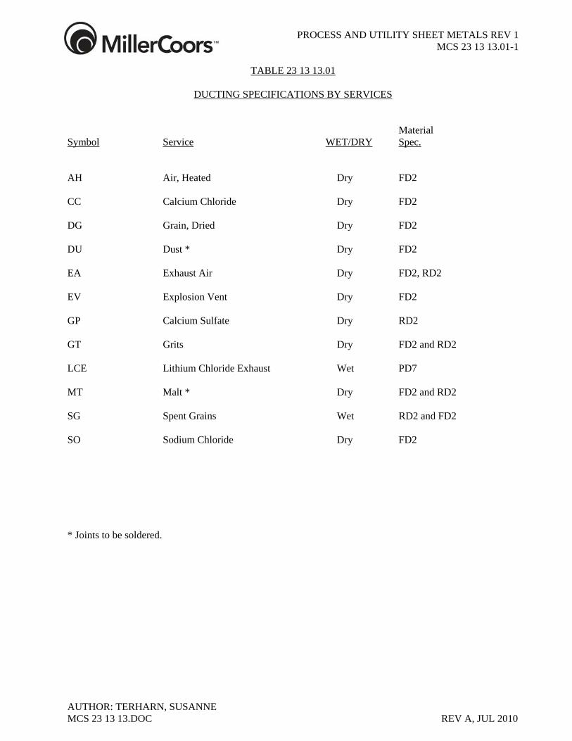
PROCESS AND UTILITY SHEET METALS REV 1
MCS 23 13 13.01-1
AUTHOR: TERHARN, SUSANNE
TABLE 23 13 13.01
DUCTING SPECIFICATIONS BY SERVICES Material Symbol Service WET/DRY Spec. AH Air, Heated Dry FD2 CC Calcium Chloride Dry FD2 DG Grain, Dried Dry FD2 DU Dust * Dry FD2 EA Exhaust Air Dry FD2, RD2 EV Explosion Vent Dry FD2 GP Calcium Sulfate Dry RD2 GT Grits Dry FD2 and RD2 LCE Lithium Chloride Exhaust Wet PD7 MT Malt * Dry FD2 and RD2 SG Spent Grains Wet RD2 and FD2 SO Sodium Chloride Dry FD2 * Joints to be soldered.
MCS 23 13 13.DOC REV A, JUL 2010
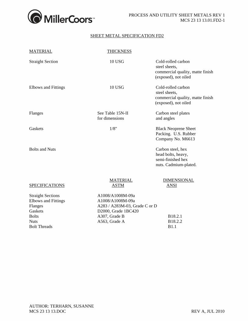
PROCESS AND UTILITY SHEET METALS REV 1
MCS 23 13 13.01.FD2-1
AUTHOR: TERHARN, SUSANNE
SHEET METAL SPECIFICATION FD2
MATERIAL THICKNESS Straight Section 10 USG Cold-rolled carbon steel sheets, commercial quality, matte finish
(exposed), not oiled Elbows and Fittings 10 USG Cold-rolled carbon steel sheets, commercial quality, matte finish
(exposed), not oiled Flanges See Table 15N-II Carbon steel plates for dimensions and angles Gaskets 1/8" Black Neoprene Sheet Packing. U.S. Rubber Company No. M6613 Bolts and Nuts Carbon steel, hex head bolts, heavy, semi-finished hex nuts. Cadmium-plated. MATERIAL DIMENSIONAL SPECIFICATIONS ASTM ANSI Straight Sections A1008/A1008M-09a Elbows and Fittings A1008/A1008M-09a Flanges A283 / A283M-03, Grade C or D Gaskets D2000, Grade 1BC420 Bolts A307, Grade B B18.2.1 Nuts A563, Grade A B18.2.2 Bolt Threads B1.1
MCS 23 13 13.DOC REV A, JUL 2010
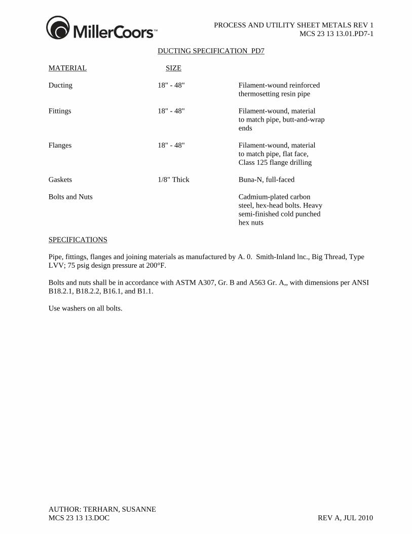
PROCESS AND UTILITY SHEET METALS REV 1
MCS 23 13 13.01.PD7-1
AUTHOR: TERHARN, SUSANNE
DUCTING SPECIFICATION PD7
MATERIAL SIZE Ducting 18" - 48" Filament-wound reinforced thermosetting resin pipe Fittings 18" - 48" Filament-wound, material to match pipe, butt-and-wrap ends Flanges 18" - 48" Filament-wound, material to match pipe, flat face, Class 125 flange drilling Gaskets 1/8" Thick Buna-N, full-faced Bolts and Nuts Cadmium-plated carbon steel, hex-head bolts. Heavy semi-finished cold punched hex nuts SPECIFICATIONS Pipe, fittings, flanges and joining materials as manufactured by A. 0. Smith-Inland lnc., Big Thread, Type LVV; 75 psig design pressure at 200°F. Bolts and nuts shall be in accordance with ASTM A307, Gr. B and A563 Gr. A,, with dimensions per ANSI B18.2.1, B18.2.2, B16.1, and B1.1. Use washers on all bolts.
MCS 23 13 13.DOC REV A, JUL 2010
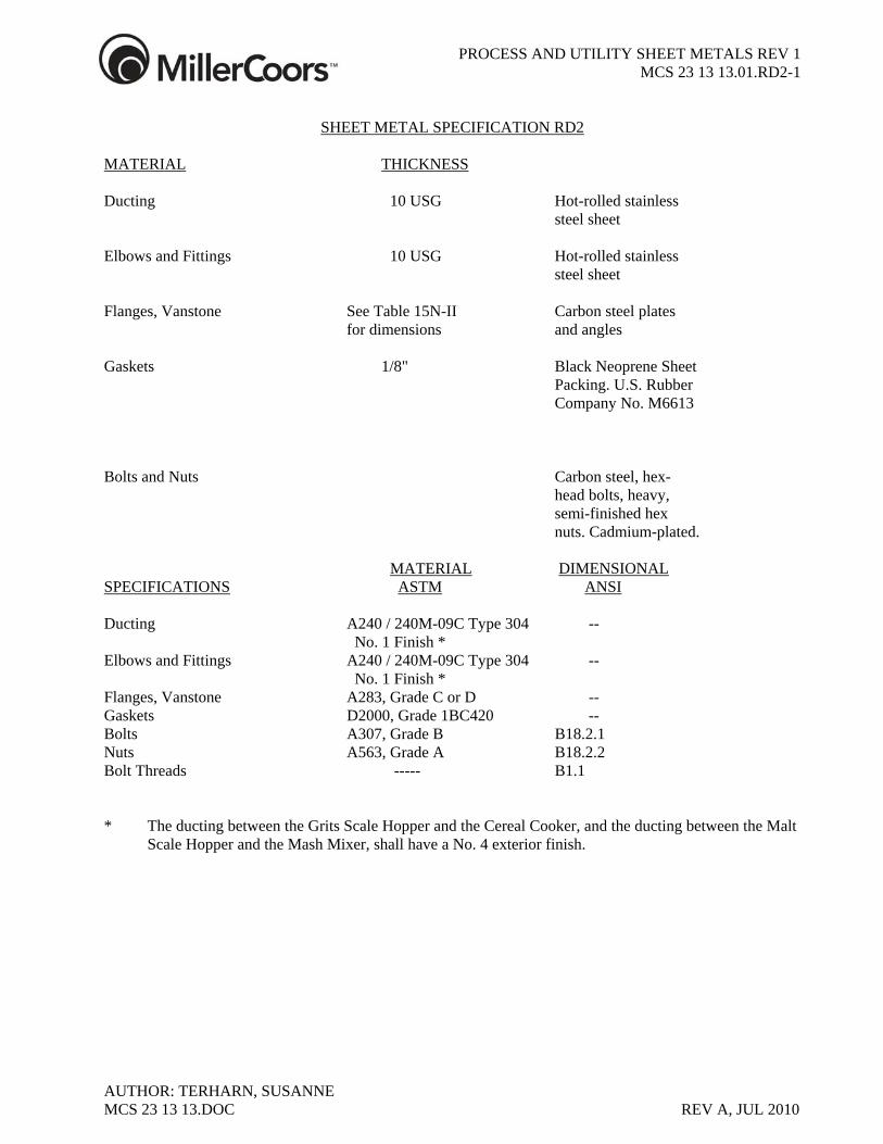
PROCESS AND UTILITY SHEET METALS REV 1
MCS 23 13 13.01.RD2-1
AUTHOR: TERHARN, SUSANNE
SHEET METAL SPECIFICATION RD2
MATERIAL THICKNESS Ducting 10 USG Hot-rolled stainless steel sheet Elbows and Fittings 10 USG Hot-rolled stainless steel sheet Flanges, Vanstone See Table 15N-II Carbon steel plates for dimensions and angles Gaskets 1/8" Black Neoprene Sheet Packing. U.S. Rubber Company No. M6613 Bolts and Nuts Carbon steel, hex- head bolts, heavy, semi-finished hex nuts. Cadmium-plated. MATERIAL DIMENSIONAL SPECIFICATIONS ASTM ANSI Ducting A240 / 240M-09C Type 304 -- No. 1 Finish * Elbows and Fittings A240 / 240M-09C Type 304 -- No. 1 Finish * Flanges, Vanstone A283, Grade C or D -- Gaskets D2000, Grade 1BC420 -- Bolts A307, Grade B B18.2.1 Nuts A563, Grade A B18.2.2 Bolt Threads ----- B1.1 * The ducting between the Grits Scale Hopper and the Cereal Cooker, and the ducting between the Malt
Scale Hopper and the Mash Mixer, shall have a No. 4 exterior finish.
MCS 23 13 13.DOC REV A, JUL 2010
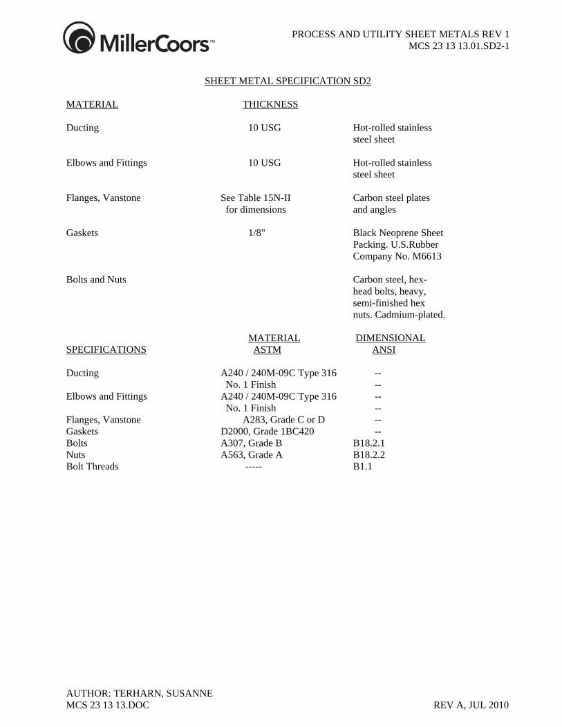
PROCESS AND UTILITY SHEET METALS REV 1
MCS 23 13 13.01.SD2-1
AUTHOR: TERHARN, SUSANNE
SHEET METAL SPECIFICATION SD2
MATERIAL THICKNESS Ducting 10 USG Hot-rolled stainless steel sheet Elbows and Fittings 10 USG Hot-rolled stainless steel sheet Flanges, Vanstone See Table 15N-II Carbon steel plates for dimensions and angles Gaskets 1/8" Black Neoprene Sheet Packing. U.S.Rubber Company No. M6613 Bolts and Nuts Carbon steel, hex- head bolts, heavy, semi-finished hex nuts. Cadmium-plated. MATERIAL DIMENSIONAL SPECIFICATIONS ASTM ANSI Ducting A240 / 240M-09C Type 316 -- No. 1 Finish -- Elbows and Fittings A240 / 240M-09C Type 316 -- No. 1 Finish -- Flanges, Vanstone A283, Grade C or D -- Gaskets D2000, Grade 1BC420 -- Bolts A307, Grade B B18.2.1 Nuts A563, Grade A B18.2.2 Bolt Threads ----- B1.1
MCS 23 13 13.DOC REV A, JUL 2010
PROCESS AND UTILITY SHEET METALS REV 1
MCS 23 13 13.02-1
AUTHOR: TERHARN, SUSANNE
TABLE 23 13 13.02
ROUND FLANGE DIMENSIONS
Round flange dimensions and bolting shall conform to SMACNA “Round Industrial Duct Construction Standards”: For Carbon and Galvanized Flanges use Tables 12-7, 12-7a, 12-7b, 12-7c and 12-7b. For flanges mating with 125-lb and 150-lb flanges use Tables 12-8, 12-9 and 12-10. For Stainless steel flanges use Table 12-12
MCS 23 13 13.DOC REV A, JUL 2010
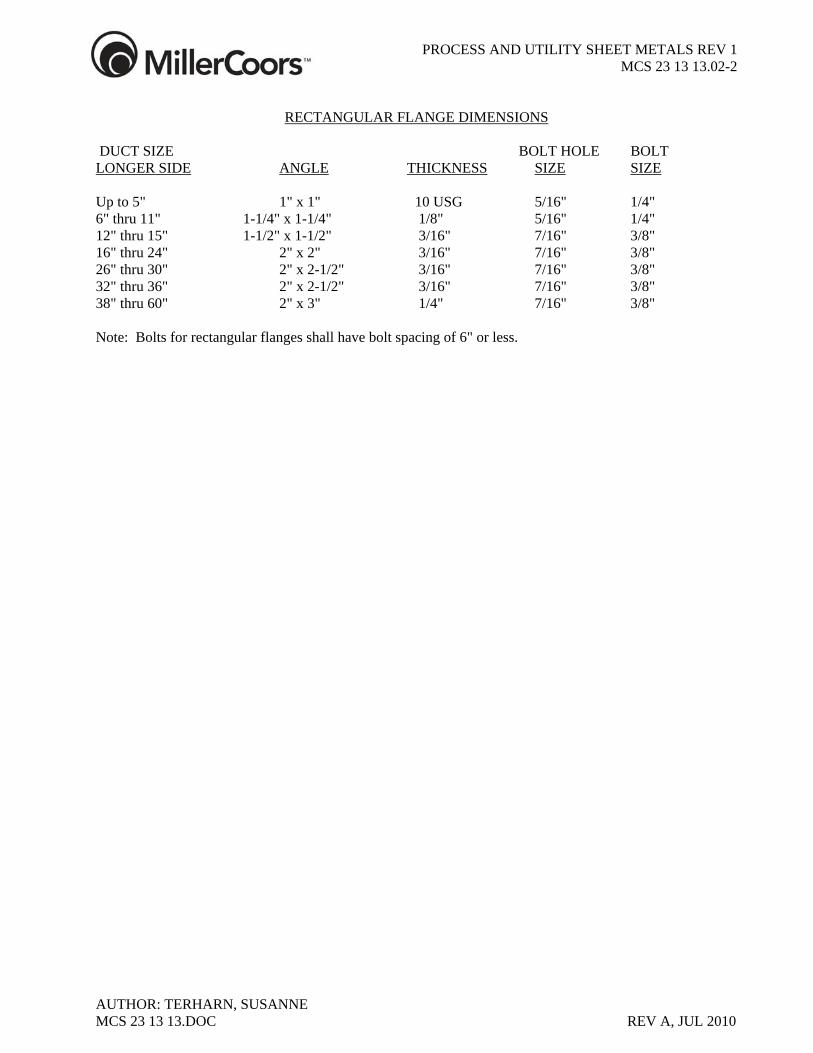
PROCESS AND UTILITY SHEET METALS REV 1
MCS 23 13 13.02-2
AUTHOR: TERHARN, SUSANNE MCS 23 13 13.DOC REV A, JUL 2010
RECTANGULAR FLANGE DIMENSIONS
DUCT SIZE BOLT HOLE BOLT LONGER SIDE ANGLE THICKNESS SIZE SIZE Up to 5" 1" x 1" 10 USG 5/16" 1/4" 6" thru 11" 1-1/4" x 1-1/4" 1/8" 5/16" 1/4" 12" thru 15" 1-1/2" x 1-1/2" 3/16" 7/16" 3/8" 16" thru 24" 2" x 2" 3/16" 7/16" 3/8" 26" thru 30" 2" x 2-1/2" 3/16" 7/16" 3/8" 32" thru 36" 2" x 2-1/2" 3/16" 7/16" 3/8" 38" thru 60" 2" x 3" 1/4" 7/16" 3/8" Note: Bolts for rectangular flanges shall have bolt spacing of 6" or less.
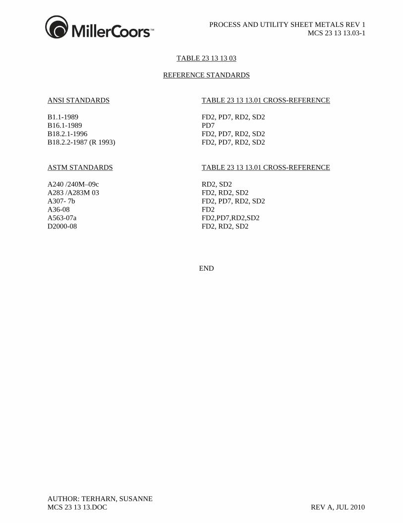
PROCESS AND UTILITY SHEET METALS REV 1
MCS 23 13 13.03-1
AUTHOR: TERHARN, SUSANNE
TABLE 23 13 13 03
REFERENCE STANDARDS
ANSI STANDARDS TABLE 23 13 13.01 CROSS-REFERENCE B1.1-1989 FD2, PD7, RD2, SD2 B16.1-1989 PD7 B18.2.1-1996 FD2, PD7, RD2, SD2 B18.2.2-1987 (R 1993) FD2, PD7, RD2, SD2 ASTM STANDARDS TABLE 23 13 13.01 CROSS-REFERENCE A240 /240M–09c RD2, SD2 A283 /A283M 03 FD2, RD2, SD2 A307- 7b FD2, PD7, RD2, SD2 A36-08 FD2 A563-07a FD2,PD7,RD2,SD2 D2000-08 FD2, RD2, SD2
END
MCS 23 13 13.DOC REV A, JUL 2010


![WELDING REQUIREMENTS [REP] - Tecton Services, …tectoninc.com/wp-content/uploads/tecton-web-projects... · Web viewRadiography on all joints per ANSI B31.1, latest revision, Chapter](https://img.pdfslide.net/doc/110x75/5a9e6cd07f8b9a67178b585f/docwelding-requirements-rep-tecton-services-viewradiography-on-all-joints.jpg)


![31 Tecton Edificio Highpoint [1]](https://img.pdfslide.net/doc/110x75/55640d59d8b42a0d0c8b4e15/31-tecton-edificio-highpoint-1.jpg)