Embed Size (px)
Citation preview
Manual Traffic and Road Use Management Volume 3 – Signing and Pavement Marking
Part 5: Design Guide for Roadside Signs November 2018
Traffic and Road Use Management, Transport and Main Roads, November 2018
Copyright
© The State of Queensland (Department of Transport and Main Roads) 2018.
Licence
This work is licensed by the State of Queensland (Department of Transport and Main Roads) under
a Creative Commons Attribution (CC BY) 4.0 International licence.
CC BY licence summary statement
In essence, you are free to copy, communicate and adapt this work, as long as you attribute the
work to the State of Queensland (Department of Transport and Main Roads). To view a copy of this
licence, visit: https://creativecommons.org/licenses/by/4.0/
Translating and interpreting assistance
The Queensland Government is committed to providing accessible services to
Queenslanders from all cultural and linguistic backgrounds. If you have difficulty
understanding this publication and need a translator, please call the Translating and
Interpreting Service (TIS National) on 13 14 50 and ask them to telephone the
Queensland Department of Transport and Main Roads on 13 74 68.
Disclaimer
While every care has been taken in preparing this publication, the State of Queensland accepts no
responsibility for decisions or actions taken as a result of any data, information, statement or
advice, expressed or implied, contained within. To the best of our knowledge, the content was
correct at the time of publishing.
Feedback
Please send your feedback regarding this document to: [email protected]
Traffic and Road Use Management, Transport and Main Roads, November 2018 i
Contents
1 Scope and introduction .................................................................................................................1
1.1 Scope .............................................................................................................................................. 1
1.2 Application ...................................................................................................................................... 1
1.3 Objective ......................................................................................................................................... 1
1.4 Introduction ..................................................................................................................................... 1
1.5 Referenced documents ................................................................................................................... 1
1.6 Definitions ....................................................................................................................................... 1
2 Design wind pressure ...................................................................................................................2
2.1 General ........................................................................................................................................... 2
2.2 Safe failure mode ............................................................................................................................ 2
2.3 Importance Level ............................................................................................................................ 2
2.4 Pressure reduction factor ................................................................................................................ 2
2.5 Regions ........................................................................................................................................... 2
2.6 Terrain Category ............................................................................................................................. 2
2.7 Gantries and cantilevers ................................................................................................................. 2
2.8 Special locations ............................................................................................................................. 3
2.9 Selection of region and exposure ................................................................................................... 3
2.10 Additional information ..................................................................................................................... 3
3 Clear zone criteria ..........................................................................................................................5
3.1 General ........................................................................................................................................... 5
4 Sign face construction ..................................................................................................................6
4.1 Sign face materials ......................................................................................................................... 6
4.2 Sign face construction .................................................................................................................... 6
4.2.1 Construction types ..........................................................................................................6 4.2.2 Standard construction ....................................................................................................7 4.2.3 Plank board construction ................................................................................................7 4.2.4 Modular construction ......................................................................................................9 4.2.5 Dovetail construction ................................................................................................... 12
5 Sign supports .............................................................................................................................. 16
5.1 Post size and selection ................................................................................................................. 16
5.2 Single post signs ........................................................................................................................... 16
5.2.1 Signs up to 950mm wide ............................................................................................. 16 5.2.2 Sign posts .................................................................................................................... 16 5.2.3 Fittings ......................................................................................................................... 17 5.2.4 Signs over 950mm wide .............................................................................................. 17 5.2.5 Posts in sleeves ........................................................................................................... 17
5.3 Multiple support signs ................................................................................................................... 17
5.3.1 Panel stiffener rails ...................................................................................................... 18 5.3.2 Sign supports ............................................................................................................... 18 5.3.3 Alternative post section sizes ...................................................................................... 19 5.3.4 Breakaway supports .................................................................................................... 19
5.4 Fittings .......................................................................................................................................... 21
Traffic and Road Use Management, Transport and Main Roads, November 2018 ii
5.4.1 Connection straps........................................................................................................ 21 5.4.2 Erection cleats ............................................................................................................. 21
5.5 Proprietary sign supports .............................................................................................................. 21
5.6 Sight boards and other signs at T-intersections ........................................................................... 21
6 Storage and handling of signs .................................................................................................. 22
6.1 General ......................................................................................................................................... 22
6.2 General storage ............................................................................................................................ 22
6.3 Indoor storage ............................................................................................................................... 22
6.4 Outdoor storage ............................................................................................................................ 22
6.5 Sign transport................................................................................................................................ 22
6.6 Sign erection ................................................................................................................................. 22
6.7 Sign covering ................................................................................................................................ 23
6.8 Sign cleaning ................................................................................................................................ 23
Appendix A: TraSiS ............................................................................................................................. 25
Appendix B: Design procedure for roadside sign support ............................................................. 26
Appendix C: Standard Drawings ....................................................................................................... 56
Appendix D: Development of the 2018 Design Guide ..................................................................... 57
D1 Background ................................................................................................................................... 57
D2 Design wind pressure ................................................................................................................... 57
D2.1 Previous Guide ............................................................................................................ 57 D2.2 2018 Design Guide ...................................................................................................... 58
D3 Design method .............................................................................................................................. 59
D3.1 Stiffener arrangement .................................................................................................. 59 D3.2 Post size and selection ................................................................................................ 59
D4 Drawings ....................................................................................................................................... 59
D5 AS4100 Steel Structures Code ..................................................................................................... 60
D6 Breakaway posts .......................................................................................................................... 60
D6.1 Risk .............................................................................................................................. 60 D6.2 Frangible posts ............................................................................................................ 60 D6.3 Criteria ......................................................................................................................... 60 D6.4 Post type ...................................................................................................................... 60 D6.5 Details .......................................................................................................................... 61
D7 Posts types ................................................................................................................................... 62
D8 Stiffener rails ................................................................................................................................. 62
D9 Single post signs ........................................................................................................................... 62
D10 Footings ........................................................................................................................................ 62
D10.1 Design strategy ............................................................................................................ 62
D11 Modular sign panels ...................................................................................................................... 63
Appendix E: Design of sight boards and other signs at T-intersections ...................................... 64
E1 Background ................................................................................................................................... 64
E2 Risk characteristic ......................................................................................................................... 64
E3 Sign design for sight boards and other signs to prevent sign spearing ........................................ 64
E4 Guidelines to the installation of new sightboards ......................................................................... 64
Traffic and Road Use Management, Transport and Main Roads, November 2018 iii
E4.1 Provision to install a sign board ................................................................................... 64 E4.2 Treatment type selection ............................................................................................. 65
Tables
Table 1.6 – Definitions ............................................................................................................................. 1
Table 2.10 – Application tables for regions ............................................................................................. 3
Table 5.2.1(a) – Hole spacing for sign blanks ....................................................................................... 16
Table 5.2.1(b) – Hole spacing for imperial flattened posts .................................................................... 16
Table 5.3.4 – Small size steel posts considered as frangible ............................................................... 20
Table B.1 – Stiffener type and number of supports ............................................................................... 28
Table B.2 – Maximum stiffener overhang .............................................................................................. 28
Table B.3 – Number of panel stiffeners ................................................................................................. 29
Table B.4 – Foundation strength category ............................................................................................ 30
Table B.5 – CHS post section equivalence table .................................................................................. 31
Figures
Figure 2.10 – Geographic region ............................................................................................................. 4
Figure 4.2.1 – Standard, plank board, modular and dovetail construction .............................................. 6
Figure 4.2.2 – Standard construction (stiffener on sign edge) ................................................................ 7
Figure 4.2.3(a) – Plank board construction ............................................................................................. 8
Figure 4.2.3(b) – Plank board construction ............................................................................................. 9
Figure 4.2.4(a) – Modular construction ................................................................................................. 10
Figure 4.2.4(b) – Modular sign panel details ......................................................................................... 11
Figure 4.2.5(a) – Dovetail construction ................................................................................................. 13
Figure 4.2.5(b) – Dovetail channel sections .......................................................................................... 14
Figure 4.2.5(c) – Dovetail post fixing ..................................................................................................... 15
Figure 5.3.4 – Impact performance ....................................................................................................... 20
Figure B.1 – Geographic region ............................................................................................................ 27
Figure B.2 – Region A, RHS / CHS posts: Sign area ≤10m² ................................................................ 32
Figure B.3– Region B, RHS / CHS posts: Sign area ≤10m² ................................................................. 34
Figure B.4 – Region C, RHS / CHS posts: Sign area ≤10m² ................................................................ 36
Figure B.5 – Region D, RHS / CHS posts: Sign area ≤10m² ................................................................ 38
Figure B.6 – Region A, RHS / CHS posts: Sign area ≤28m² ................................................................ 40

Traffic and Road Use Management, Transport and Main Roads, November 2018 iv
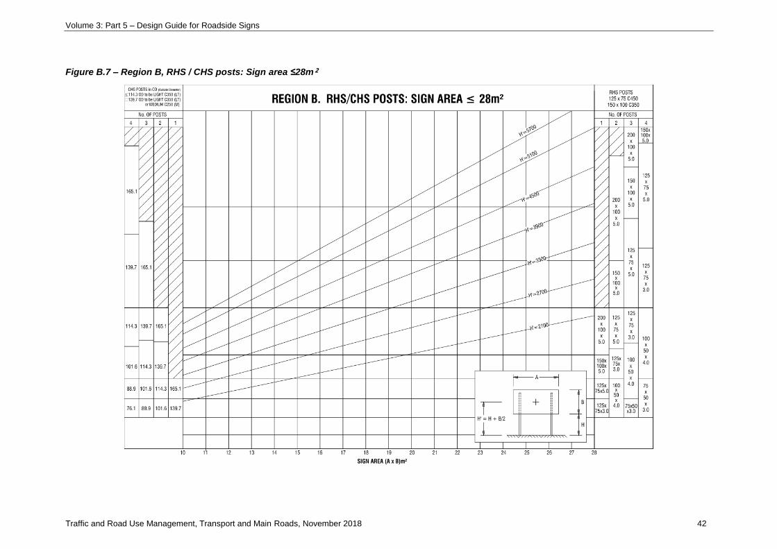
Figure B.7 – Region B, RHS / CHS posts: Sign area ≤28m² ................................................................ 42
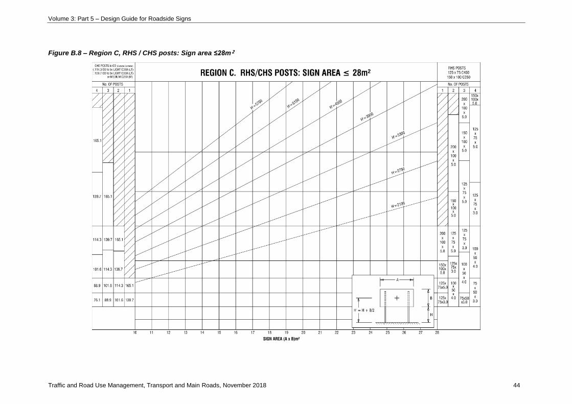
Figure B.8 – Region C, RHS / CHS posts: Sign area ≤28m² ................................................................ 44
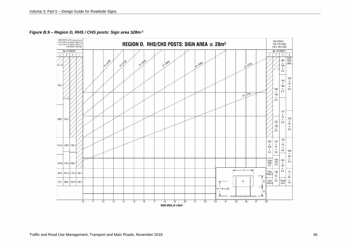
Figure B.9 – Region D, RHS / CHS posts: Sign area ≤28m² ................................................................ 46
Figure B.10 – Region A, RHS / CHS posts: Sign area ≤40m² .............................................................. 48
Figure B.11 – Region B, RHS / CHS posts: Sign area ≤40m² .............................................................. 50
Figure B.12 – Region C, RHS / CHS posts: Sign area ≤40m² .............................................................. 52
Figure B.13 – Region D, RHS / CHS posts: Sign area ≤40m² .............................................................. 54
Figure E4 – Flowchart for design of sightboards and direction signs at T-intersections ....................... 65
Volume 3: Part 5 – Design Guide for Roadside Signs
Traffic and Road Use Management, Transport and Main Roads, November 2018 1
1 Scope and introduction
1.1 Scope
This Guide sets out guidelines for the design and erection of roadside signs.
This Guide does not cover cantilevers and gantries that overhang the carriageway.
1.2 Application
This Guide is applicable to all types of roads under normal operating conditions.
1.3 Objective
The objective of this Guide is to provide a set of uniform guidelines for the design and erection of
roadside signs throughout Queensland.
1.4 Introduction
The procedure for the design of signs in this Guide should be applied from the initial design of the sign
face through to the ordering of each sign component. The software program TraSiS guides the user
through the design process. Appendix A provides details on the program together with information on
how to purchase a copy.
1.5 Referenced documents
Australian Standard AS/NZS 1170.2 2011 Structural Design Actions, Part 2: Wind Loads is referenced
in this Guide, as are the Transport and Main Roads Specifications Manual and the Standard Drawings
Manual.
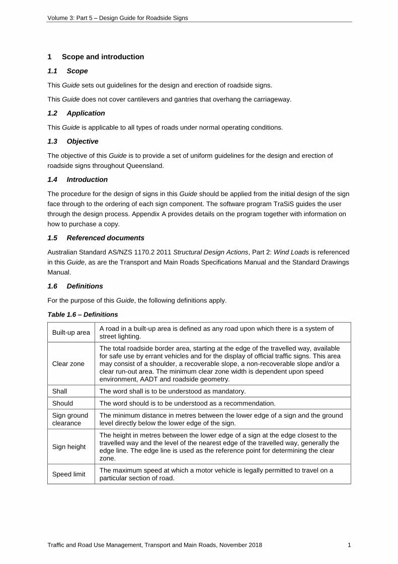
1.6 Definitions
For the purpose of this Guide, the following definitions apply.
Table 1.6 – Definitions
Built-up area A road in a built-up area is defined as any road upon which there is a system of street lighting.
Clear zone
The total roadside border area, starting at the edge of the travelled way, available for safe use by errant vehicles and for the display of official traffic signs. This area may consist of a shoulder, a recoverable slope, a non-recoverable slope and/or a clear run-out area. The minimum clear zone width is dependent upon speed environment, AADT and roadside geometry.
Shall The word shall is to be understood as mandatory.
Should The word should is to be understood as a recommendation.
Sign ground clearance
The minimum distance in metres between the lower edge of a sign and the ground level directly below the lower edge of the sign.
Sign height
The height in metres between the lower edge of a sign at the edge closest to the travelled way and the level of the nearest edge of the travelled way, generally the edge line. The edge line is used as the reference point for determining the clear zone.
Speed limit The maximum speed at which a motor vehicle is legally permitted to travel on a particular section of road.
Volume 3: Part 5 – Design Guide for Roadside Signs
Traffic and Road Use Management, Transport and Main Roads, November 2018 2
2 Design wind pressure
2.1 General
Earlier versions of this Design Guide dating back to 1993 adopted a strategy of using an appropriate
probability of exceedance of the wind speed to derive support structure sizing that was considered
acceptable to both structure ‘design life’ and road safety (collision). The chance of exceedance in
50-year and one-year return periods was 96% and 6.5% respectively. This updated Edition derives
similar design wind pressures, determined in accordance with the current Australian Standards and
with the application of a pressure reduction factor, R.
The following sections outline the structural assumptions made in this Guide. The design process is
based on AS/NZS 1170.2-2011.
2.2 Safe failure mode
The design strategy is based on a safe failure mode of support post yielding and bending prior to
failure of the sign face and its attachment to the posts. To ensure that signs are not blown off before
the poles bend, aluminium stiffener rails and sign face are designed to accommodate peak edge
pressures generated by the critical 45-degree wind approach angle, Terrain Category 2 (fully exposed)
and with an additional safety factor of 1.5 applied to the post design pressure.
2.3 Importance Level
Importance Level 1 in accordance with AS/NZS 1170:0 Appendix F is used on the basis of ‘small or
moderate’ economic consequence and safe failure mode with failure unlikely to endanger human life.
A design working life of 25-year design life is considered appropriate and this yields an annual
probability of exceedance of 1 in 100 (1/100) for cyclonic and non-cyclonic wind speed.
2.4 Pressure reduction factor
A pressure reduction factor, R = 0.5, is applied to the ultimate support post design pressure derived in
accordance with AS/NZS 1170.2-2011. This factor is applied to the resultant pressure derived from
wind speed and drag co-efficient.
2.5 Regions
Signs in the different geographic regions defined in AS/NZS 1170.2 (A, B, C and D) are designed for
the wind speed related to that region. Region D is included to facilitate design charts for Exposed
Region C locations (refer to Section 2.6 following).
2.6 Terrain Category
To simplify the design procedure, design charts are derived to suit general exposure as applicable to
Terrain Category 3 (terrain with numerous closely spaced obstructions 3m to 5m high). To cater for
exposed locations (Terrain Category 2 – open terrain, grasslands with few, well scattered
obstructions), the design method calls for use of charts applicable to the next higher wind region.
2.7 Gantries and cantilevers
The design philosophy outlined in sections 2.2, 2.3 and 2.4 does not apply to sign gantries or
cantilevers that extend over traffic lanes, which are excluded from the Guide. These signs should be
designed in accordance with the Design Criteria for Bridges and Other Structures.
Volume 3: Part 5 – Design Guide for Roadside Signs
Traffic and Road Use Management, Transport and Main Roads, November 2018 3
2.8 Special locations
High-risk areas likely to be exposed to high wind speeds regularly should be identified and the risk
assessed. This risk can be reduced by the use of the exposed category (Category 2 of
AS/NZS 1170.2) or an increased section size. Typical locations that should be considered are:
• Houghton Highway (across water adjacent Moreton Bay)
• Gateway Bridge (high, exposed position)
• some sections of Gateway Arterial, adjacent to Brisbane Airport, and/or
• Gold Coast Highway at Kirra and other coastal positions.
2.9 Selection of region and exposure
For those locations not listed in Section 2.8, the following procedure for the selection of the
appropriate Design Table is recommended:
1) Identify Region A, B, C – refer to Figure 2.1.
2) Consider whether or not the region is particularly exposed or at risk. If so, increase Region A to B,
B to C, and C to D.
3) Refer to Table 2.1 to determine the appropriate figure. Figures B.2–B.13 can be found in
Appendix B to this Guide.
Situations outside the scope of these tables, or standard sections, should be checked and designed
by a structural engineer. Extrapolation of these tables is neither appropriate nor acceptable.
2.10 Additional information
The Traffic Engineering and Data Unit, Engineering and Technology Branch holds design calculations,
which outline the basis for the design charts.
Based on various Australian Standards, assumptions have been made on the performance of the sign
structure as a whole. Full scale structural testing is recommended to confirm these assumptions.
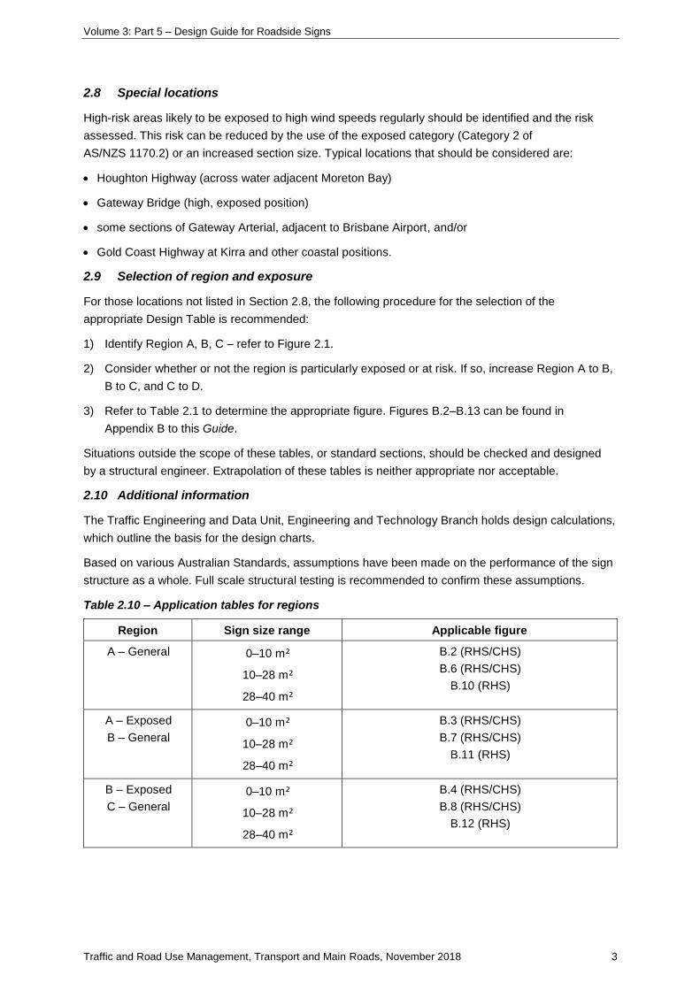
Table 2.10 – Application tables for regions
Region Sign size range Applicable figure
A – General 0–10 m²
10–28 m²
28–40 m²
B.2 (RHS/CHS)
B.6 (RHS/CHS)
B.10 (RHS)
A – Exposed
B – General
0–10 m²
10–28 m²
28–40 m²
B.3 (RHS/CHS)
B.7 (RHS/CHS)
B.11 (RHS)
B – Exposed
C – General
0–10 m²
10–28 m²
28–40 m²
B.4 (RHS/CHS)
B.8 (RHS/CHS)
B.12 (RHS)
Volume 3: Part 5 – Design Guide for Roadside Signs
Traffic and Road Use Management, Transport and Main Roads, November 2018 4
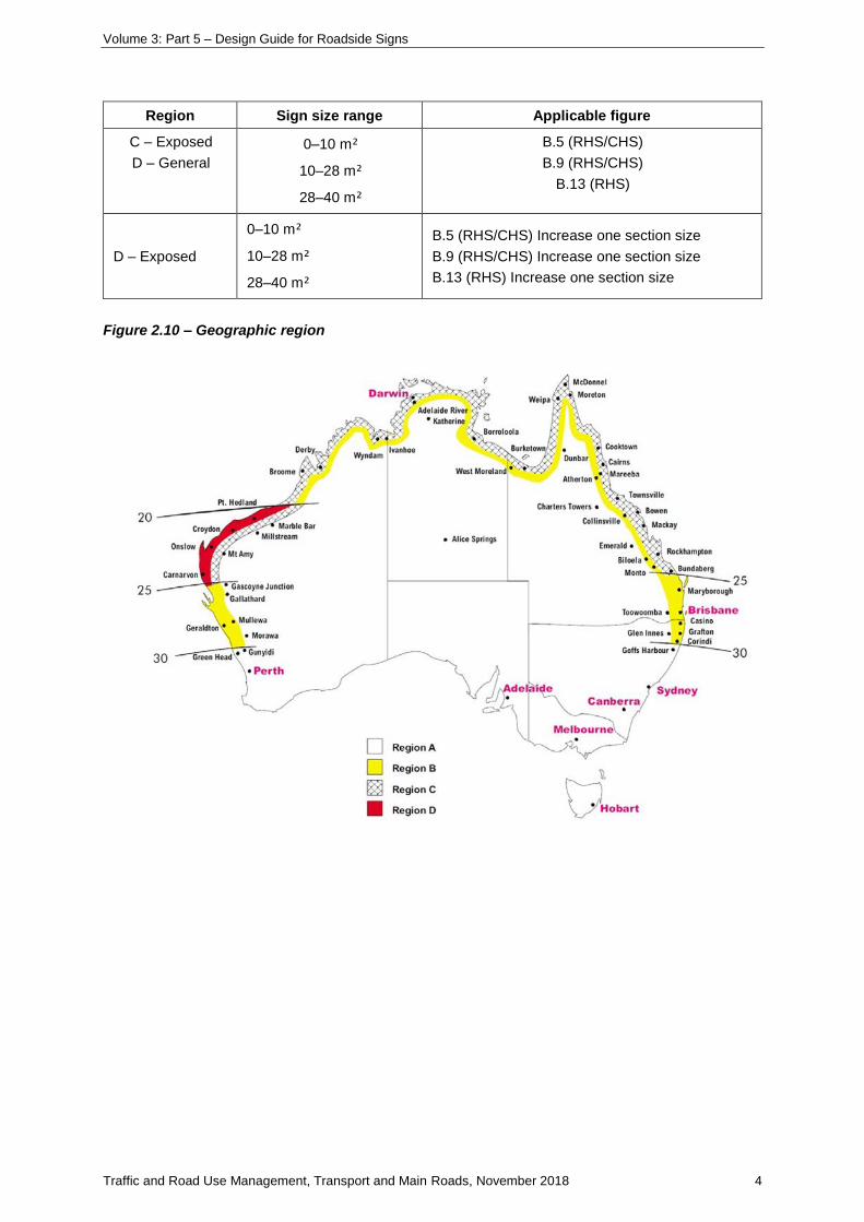
Region Sign size range Applicable figure
C – Exposed
D – General
0–10 m²
10–28 m²
28–40 m²
B.5 (RHS/CHS)
B.9 (RHS/CHS)
B.13 (RHS)
D – Exposed
0–10 m²
10–28 m²
28–40 m²
B.5 (RHS/CHS) Increase one section size
B.9 (RHS/CHS) Increase one section size
B.13 (RHS) Increase one section size
Figure 2.10 – Geographic region

Volume 3: Part 5 – Design Guide for Roadside Signs
Traffic and Road Use Management, Transport and Main Roads, November 2018 5
3 Clear zone criteria
3.1 General
Refer to Austroads’ Guide to Road Design Part 6 Section 4.2.2 for calculating clear zone distances.
Volume 3: Part 5 – Design Guide for Roadside Signs
Traffic and Road Use Management, Transport and Main Roads, November 2018 6
4 Sign face construction
4.1 Sign face materials
Refer to MRTS14 Road Furniture for details regarding the sign face material requirements.
4.2 Sign face construction
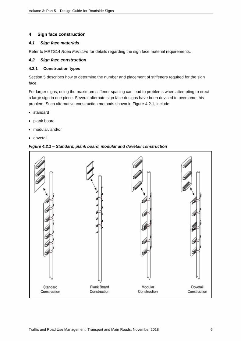
4.2.1 Construction types
Section 5 describes how to determine the number and placement of stiffeners required for the sign
face.
For larger signs, using the maximum stiffener spacing can lead to problems when attempting to erect
a large sign in one piece. Several alternate sign face designs have been devised to overcome this
problem. Such alternative construction methods shown in Figure 4.2.1, include:
• standard
• plank board
• modular, and/or
• dovetail.
Figure 4.2.1 – Standard, plank board, modular and dovetail construction
Volume 3: Part 5 – Design Guide for Roadside Signs
Traffic and Road Use Management, Transport and Main Roads, November 2018 7
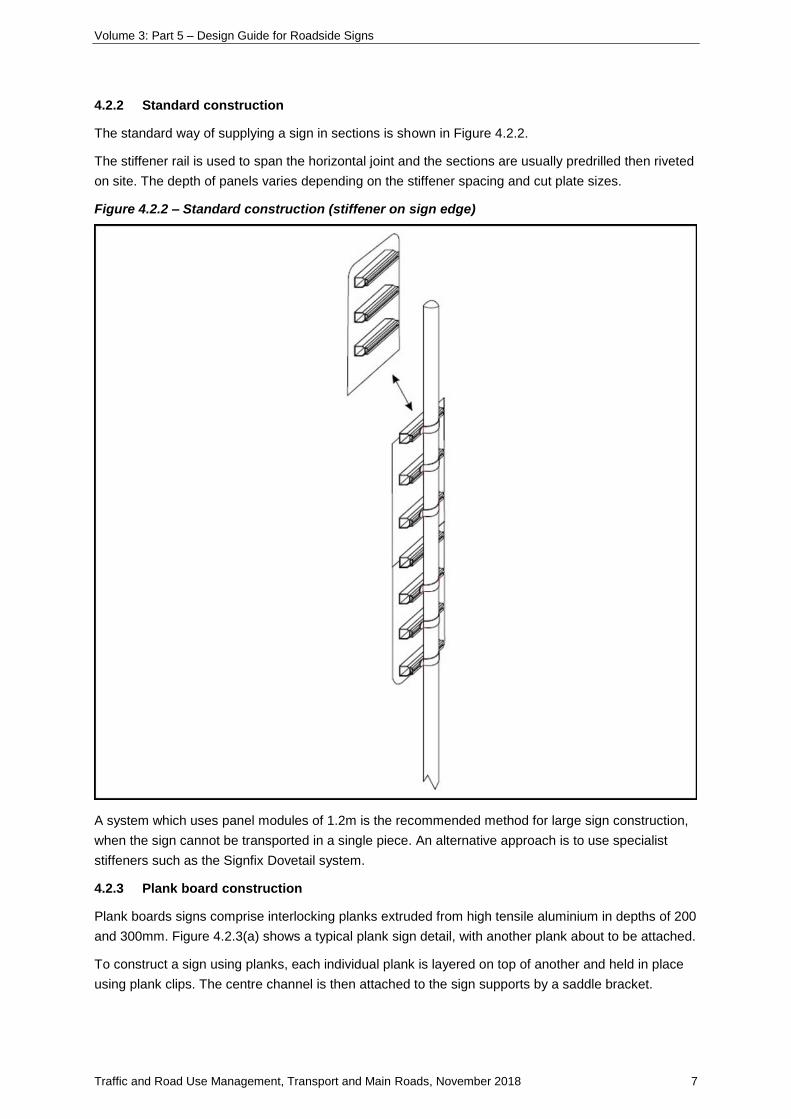
4.2.2 Standard construction
The standard way of supplying a sign in sections is shown in Figure 4.2.2.
The stiffener rail is used to span the horizontal joint and the sections are usually predrilled then riveted
on site. The depth of panels varies depending on the stiffener spacing and cut plate sizes.
Figure 4.2.2 – Standard construction (stiffener on sign edge)
A system which uses panel modules of 1.2m is the recommended method for large sign construction,
when the sign cannot be transported in a single piece. An alternative approach is to use specialist
stiffeners such as the Signfix Dovetail system.
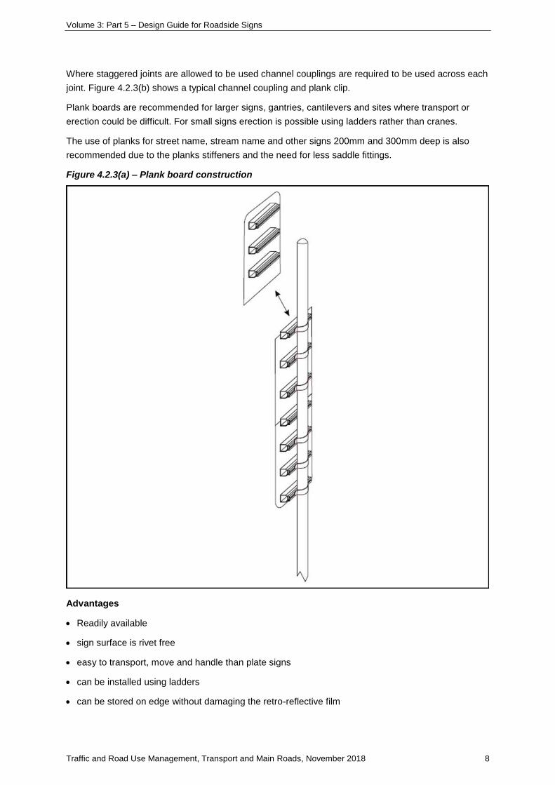
4.2.3 Plank board construction
Plank boards signs comprise interlocking planks extruded from high tensile aluminium in depths of 200
and 300mm. Figure 4.2.3(a) shows a typical plank sign detail, with another plank about to be attached.
To construct a sign using planks, each individual plank is layered on top of another and held in place
using plank clips. The centre channel is then attached to the sign supports by a saddle bracket.
Volume 3: Part 5 – Design Guide for Roadside Signs
Traffic and Road Use Management, Transport and Main Roads, November 2018 8
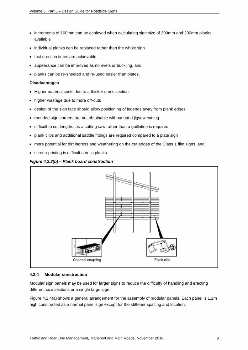
Where staggered joints are allowed to be used channel couplings are required to be used across each
joint. Figure 4.2.3(b) shows a typical channel coupling and plank clip.
Plank boards are recommended for larger signs, gantries, cantilevers and sites where transport or
erection could be difficult. For small signs erection is possible using ladders rather than cranes.
The use of planks for street name, stream name and other signs 200mm and 300mm deep is also
recommended due to the planks stiffeners and the need for less saddle fittings.
Figure 4.2.3(a) – Plank board construction
Advantages
• Readily available
• sign surface is rivet free
• easy to transport, move and handle than plate signs
• can be installed using ladders
• can be stored on edge without damaging the retro-reflective film
Volume 3: Part 5 – Design Guide for Roadside Signs
Traffic and Road Use Management, Transport and Main Roads, November 2018 9
• increments of 100mm can be achieved when calculating sign size of 300mm and 200mm planks
available
• individual planks can be replaced rather than the whole sign
• fast erection times are achievable
• appearance can be improved as no rivets or buckling, and
• planks can be re-sheeted and re-used easier than plates.
Disadvantages
• Higher material costs due to a thicker cross section
• higher wastage due to more off-cuts
• design of the sign face should allow positioning of legends away from plank edges
• rounded sign corners are not obtainable without hand jigsaw cutting
• difficult to cut lengths, as a cutting saw rather than a guillotine is required
• plank clips and additional saddle fittings are required compared to a plate sign
• more potential for dirt ingress and weathering on the cut edges of the Class 1 film signs, and
• screen-printing is difficult across planks.
Figure 4.2.3(b) – Plank board construction
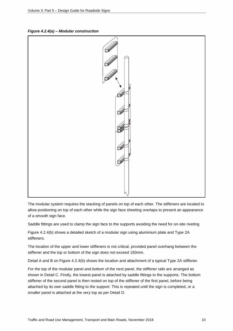
4.2.4 Modular construction
Modular sign panels may be used for larger signs to reduce the difficulty of handling and erecting
different size sections or a single large sign.
Figure 4.2.4(a) shows a general arrangement for the assembly of modular panels. Each panel is 1.2m
high constructed as a normal panel sign except for the stiffener spacing and location.
Volume 3: Part 5 – Design Guide for Roadside Signs
Traffic and Road Use Management, Transport and Main Roads, November 2018 10
Figure 4.2.4(a) – Modular construction
The modular system requires the stacking of panels on top of each other. The stiffeners are located to
allow positioning on top of each other while the sign face sheeting overlaps to present an appearance
of a smooth sign face.
Saddle fittings are used to clamp the sign face to the supports avoiding the need for on-site riveting.
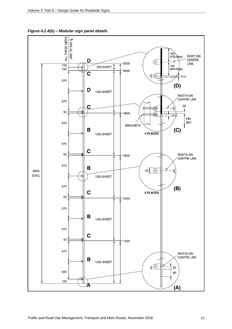
Figure 4.2.4(b) shows a detailed sketch of a modular sign using aluminium plate and Type 2A
stiffeners.
The location of the upper and lower stiffeners is not critical, provided panel overhang between the
stiffener and the top or bottom of the sign does not exceed 150mm.
Detail A and B on Figure 4.2.4(b) shows the location and attachment of a typical Type 2A stiffener.
For the top of the modular panel and bottom of the next panel, the stiffener rails are arranged as
shown in Detail C. Firstly, the lowest panel is attached by saddle fittings to the supports. The bottom
stiffener of the second panel is then rested on top of the stiffener of the first panel, before being
attached by its own saddle fitting to the support. This is repeated until the sign is completed, or a
smaller panel is attached at the very top as per Detail D.
Volume 3: Part 5 – Design Guide for Roadside Signs
Traffic and Road Use Management, Transport and Main Roads, November 2018 11
Figure 4.2.4(b) – Modular sign panel details
Volume 3: Part 5 – Design Guide for Roadside Signs
Traffic and Road Use Management, Transport and Main Roads, November 2018 12
For signs where the 580mm spread of stiffener rails could affect the visual appearance, due to minor
deformation between stiffeners, 2mm thick sheeting or additional stiffener rails should be considered.
The use of the modular system is recommended for all large signs (deeper than 1.2m) that have to be
assembled on site.
The following is a summary of advantages and disadvantages of the use of a modular system.
Advantages
• No riveting required on site
• appropriate size for transporting
• reasonable size of section for lifting by crane
• reduces the stress on cover strips and rivets during erection
• appropriate size for storage
• transportable face to face to protect retro-reflective sheeting face
• easier removal by sections and re-erection if required, and
• formalises existing practice of transporting large signs in sections to assemble on site.
Disadvantages
• Additional stiffeners required, and
• no advantage for regions close to the sign manufacturer, where large cranes are readily available
and the whole sign is transportable.
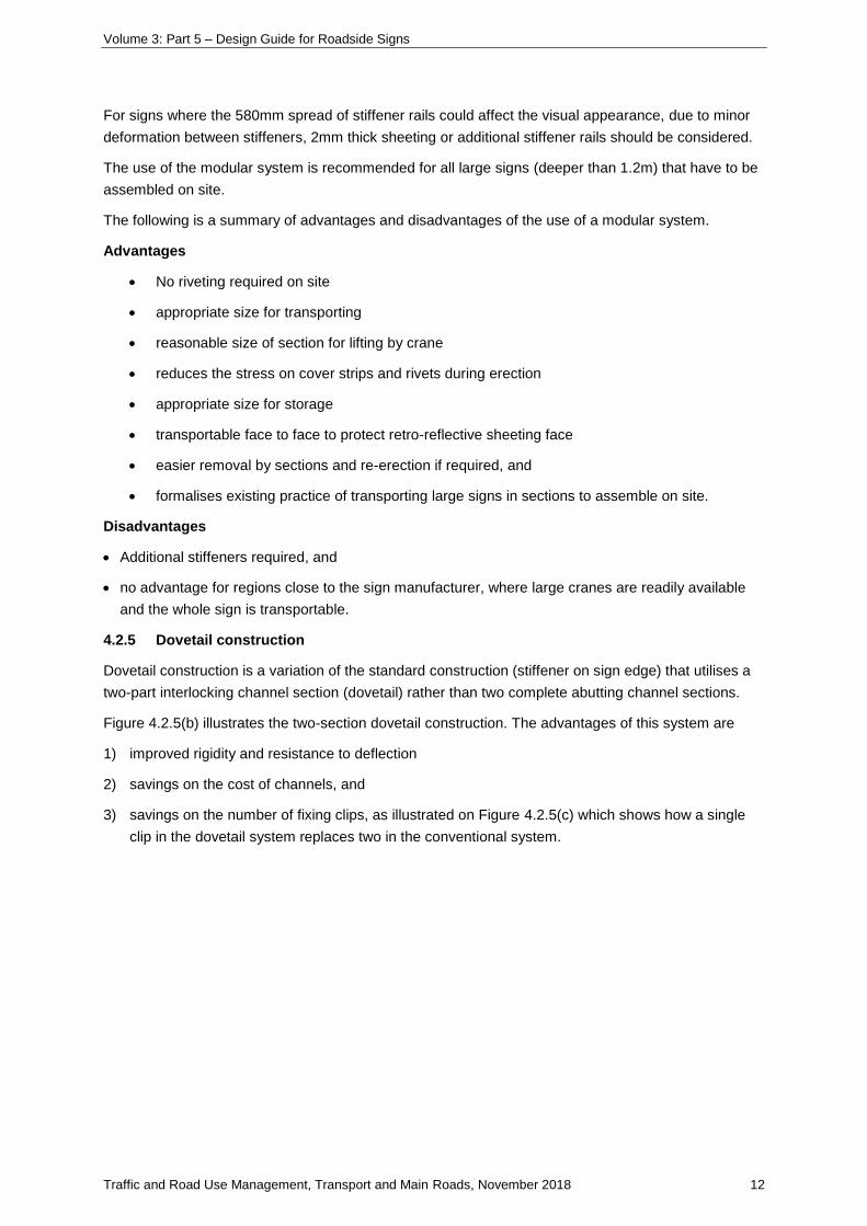
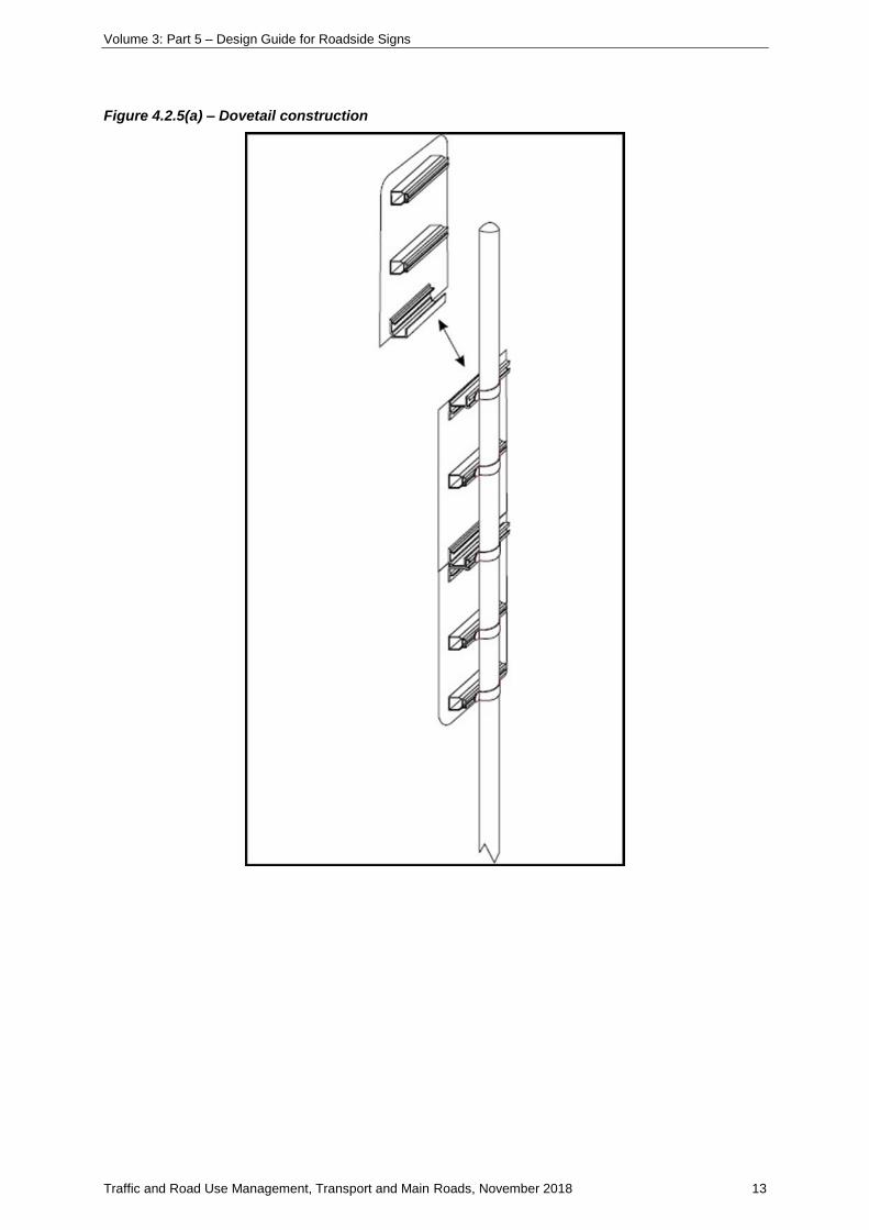
4.2.5 Dovetail construction
Dovetail construction is a variation of the standard construction (stiffener on sign edge) that utilises a
two-part interlocking channel section (dovetail) rather than two complete abutting channel sections.
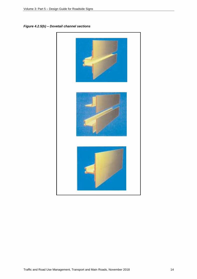
Figure 4.2.5(b) illustrates the two-section dovetail construction. The advantages of this system are
1) improved rigidity and resistance to deflection
2) savings on the cost of channels, and
3) savings on the number of fixing clips, as illustrated on Figure 4.2.5(c) which shows how a single
clip in the dovetail system replaces two in the conventional system.
Volume 3: Part 5 – Design Guide for Roadside Signs
Traffic and Road Use Management, Transport and Main Roads, November 2018 13
Figure 4.2.5(a) – Dovetail construction
Volume 3: Part 5 – Design Guide for Roadside Signs
Traffic and Road Use Management, Transport and Main Roads, November 2018 14
Figure 4.2.5(b) – Dovetail channel sections
Volume 3: Part 5 – Design Guide for Roadside Signs
Traffic and Road Use Management, Transport and Main Roads, November 2018 15
Figure 4.2.5(c) – Dovetail post fixing
Volume 3: Part 5 – Design Guide for Roadside Signs
Traffic and Road Use Management, Transport and Main Roads, November 2018 16
5 Sign supports
5.1 Post size and selection
A graphical method of post selection is used in this Guide, similar in format to that used in
AS1742.2-2009. Each geographic wind region is catered for with a separate table for clarity and ease
of use. The post size is chosen directly from the table for a given sign size, height and number of
posts. An option is given for either CHS or RHS posts.
5.2 Single post signs
5.2.1 Signs up to 950mm wide
Standard regulatory, parking, warning and guide signs up to 950mm wide are generally erected
without panel stiffeners and are supported on a single post. Sign panels greater than 700mm wide and
1000mm deep are sometimes prone to twist and panel deformation. For this reason, consideration
should be given to stiffening with Type 1 panel stiffeners.
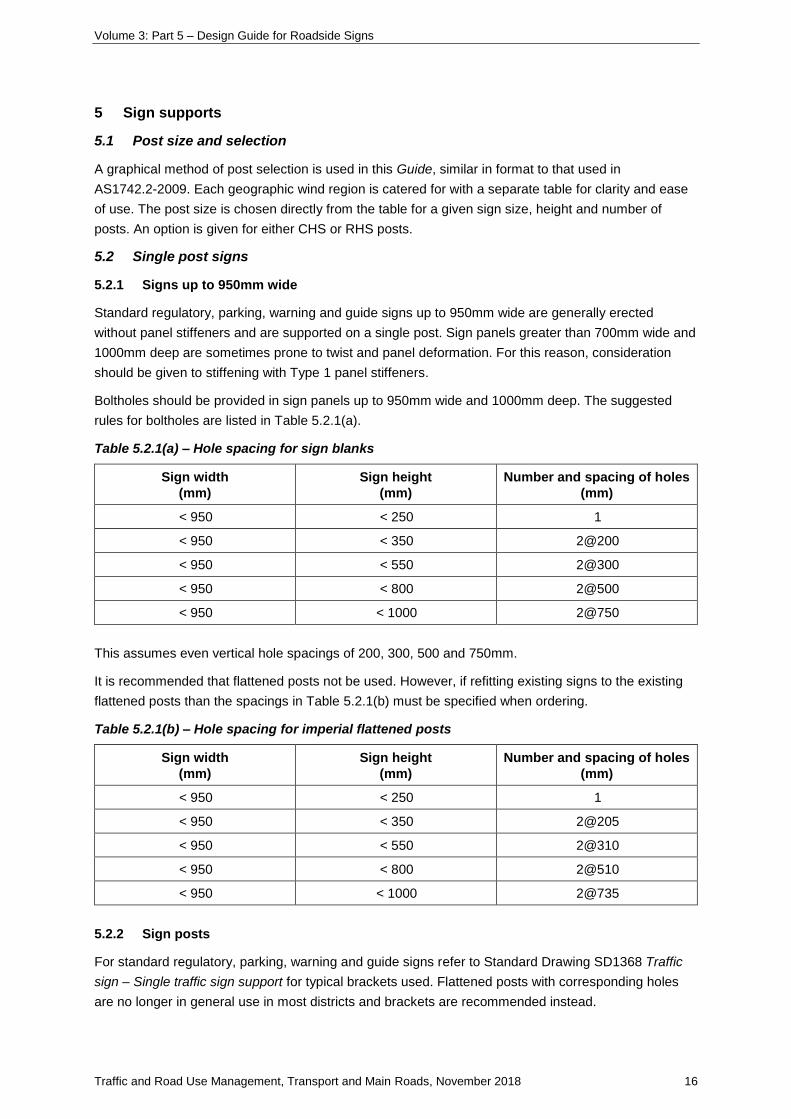
Boltholes should be provided in sign panels up to 950mm wide and 1000mm deep. The suggested
rules for boltholes are listed in Table 5.2.1(a).
Table 5.2.1(a) – Hole spacing for sign blanks
Sign width
(mm)
Sign height
(mm)
Number and spacing of holes
(mm)
< 950 < 250 1
< 950 < 350 2@200
< 950 < 550 2@300
< 950 < 800 2@500
< 950 < 1000 2@750
This assumes even vertical hole spacings of 200, 300, 500 and 750mm.
It is recommended that flattened posts not be used. However, if refitting existing signs to the existing
flattened posts than the spacings in Table 5.2.1(b) must be specified when ordering.
Table 5.2.1(b) – Hole spacing for imperial flattened posts
Sign width
(mm)
Sign height
(mm)
Number and spacing of holes
(mm)
< 950 < 250 1
< 950 < 350 2@205
< 950 < 550 2@310
< 950 < 800 2@510
< 950 < 1000 2@735
5.2.2 Sign posts
For standard regulatory, parking, warning and guide signs refer to Standard Drawing SD1368 Traffic
sign – Single traffic sign support for typical brackets used. Flattened posts with corresponding holes
are no longer in general use in most districts and brackets are recommended instead.
Volume 3: Part 5 – Design Guide for Roadside Signs
Traffic and Road Use Management, Transport and Main Roads, November 2018 17
For signs less than 1 m² in area, the post size is generally 50 DN x 3.2mm CHS. Refer to Appendix B
for determination of post sizes suitable for larger signs or heights.
Single posts will generally be CHS, although RHS should be considered for larger signs to increase
resistance to twisting.
5.2.3 Fittings
Standard Drawing SD1369 Traffic sign – Details of sign stiffening extrusion shows several basic types
of fittings referred to as Fittings B1, B2, B3, and B4. These are only for 50 DN posts and are a basic
standard only. Alternative brackets and variations on these themes are readily available and in most
cases equally effective. The user will have to consider their individual requirements before selecting a
bracket for a particular purpose. Brackets for 65 DN are available but will not normally be required.
Fittings B1 and B2 are generally used for the erection of single sided standard signs. Fitting B3 is used
to erect back-to-back standard signs on a common post.
Fitting B4, wing saddle brackets, are used for single-sided signs. These brackets provide resistance to
movement but require site drilling of the post.
5.2.4 Signs over 950mm wide
For sign faces over 950mm wide, the use of multiple support posts is generally recommended to avoid
panel twist due to vandalism or wind buffeting. For situations where a two-post support is not
possible (for example, narrow urban median strips), a single post may be used with panel stiffeners
fixed in accordance with Standard Drawing SD1368 Traffic sign – Single traffic sign support for signs
up to 1800mm wide. Refer to Appendix B for the design procedure.
If breakaway posts are required (refer to Section 5.3.4), the slip base detail given on Standard
Drawing SD1368 Traffic sign – Single traffic sign support is recommended for single post signs subject
to impact from any direction. The fuse plate detail is unnecessary and should not be used with single
post signs.
Brackets are available that resist twisting, such as the Signfix Type 5 Bracket.
5.2.5 Posts in sleeves
There are certain situations where it is advisable to install the post into a sleeve inserted into the
footing, such as:
1) where a sign is located on an urban median strip where it may be struck frequently, or
2) where it may need to be removed occasionally, to accommodate the swept path of
over-dimensioned vehicles when turning.
This arrangement is only appropriate for small posts up to 50 DN.
Details of a typical sleeve assembly are presented in Standard Drawing SD1368 Traffic sign – Single
traffic sign support. An alternative assembly called the ‘loc Socket’ is also shown on Standard Drawing
SD1368 Traffic sign – Single traffic sign support. This is a commercial product and variations on the
basic theme are just as effective.
5.3 Multiple support signs
For sign widths greater than 950mm, panel stiffener rails are attached to the sign face and connected
to two or more supports (refer to Section 5.2.4 for discussion of the single post alternative).
Volume 3: Part 5 – Design Guide for Roadside Signs
Traffic and Road Use Management, Transport and Main Roads, November 2018 18
The term support here refers to a CHS or RHS post. This Guide may be used for signs up to 8m in
height and up to 8m in width, with a maximum area of 40m².
5.3.1 Panel stiffener rails
Two panel stiffener sections are used in fabrication of signs greater than 950mm in width, Type 1 and
Type 2A. Refer to Standard Drawing SD1369 Traffic sign – Details of sign stiffening extrusion for
specification of aluminium extrusions.
Stiffener type and number is derived from Appendix B, tables B.1, B.2 and B.3 for a particular sign
width, height and location. Table B.1 presents three options for choice of stiffener type and number of
supports:
Option 1: The most economical option using a minimum number of supports spaced at the standard
spacing of 60% and 35% of sign width for two and three support signs respectively.
Option 2: This alternative arrangement may be adopted where an additional support is used to
achieve ‘frangible’ section sizes. Note the limitations on support spacing to achieve a satisfactory
‘frangible’ solution. This option maintains the standard support spacings to derive the maximum sign
width; however, reduced post spacing may be used as long as the maximum stiffener overhang is not
exceeded.
Option 3: An option for signs requiring two widely spaced supports, for example, straddling a footpath,
where the minimum overhang is 10% of sign width.
For sign widths less than the tabulated limits, the support spacing may be reduced below the standard
spacing ratio to suit the site conditions; however, the maximum stiffener overhang specified in
Table B.2 must not be exceeded.
Additional posts may be used to achieve ‘frangible’ section sizes if required; however, increasing the
number of posts is not a valid method for resultant post spacing less than 1.5m, due to the increased
likelihood of collision with two posts
Deviation from the specified stiffener / support arrangements will require calculation of width limits in
accordance with the appropriate formulae.
General constraints on stiffener arrangements are as follows:
• 500mm maximum stiffener spacing, and
• 150mm maximum panel overhang between stiffeners and top and bottom of sign.
For large signs erected using modular panels, refer to Section 4.
5.3.2 Sign supports
Tubular steel posts are used to support the stiffened sign panel, either Circular Hollow Section (CHS)
or Rectangular Hollow Section (RHS).
The number of supports and options for support type (RHS / CHS) are determined from the procedure
in Appendix B. The selection of support type is influenced by the following considerations:
CHS has generally been the preferred post type due to:
• availability as pregalvanised (300g/ms), which saves the cost and inconvenience of hot dip
galvanising RHS
• less wastage in fabrication due to 6.5m length stock sizes compared to 8m for RHS
Volume 3: Part 5 – Design Guide for Roadside Signs
Traffic and Road Use Management, Transport and Main Roads, November 2018 19
• less tolerance on length required due to ease of pipe cutting and capping on site
• less tolerance on alignment with sign face required
• availability of fittings, and
• more easily realigned if bent over by wind or vehicle impact.
RHS posts are significantly more efficient than CHS as structural sections, particularly with the benefit
of availability as Grade C350/450.
In regions of Mild and Moderate Atmospheric Classification¹, advantage may be taken of
pregalvanised (100g/ms) RHS which has recently become available for sizes up to 125 x 75 and is
half the cost of equivalent capacity galvanised CHS. This cost saving should be considered against
the erection advantages of CHS.
Note: ¹Atmospheric Classification is as defined in AS2312 with Moderate zones having rainfall less than 1000mm
p.a., average humidity 50 to 80% and being situated further than 15km from the coast, with only light industrial
activity.
In urban areas, the likelihood of corrosion from dog urine should also be considered. Although urine
will attack all levels of galvanising, the heavier hot dip galvanised coating will give greater protection to
the steel.
Posts for signs located in ‘high risk’ areas which are ‘non-frangible’ (refer Section 5.3.4), must be hot
dip galvanised after fabrication of slip baseplate and fuse plate hinge details as specified in Standard
Drawing SD1365 Traffic Sign – Traffic sign support breakaway post details (two or more supports).
The cost and convenience benefits inherent in having CHS pre-galvanised are therefore removed and
the cost savings of RHS, as discussed previously, should be considered.
Posts in sleeves (refer Section 5.2.5) must be CHS posts.
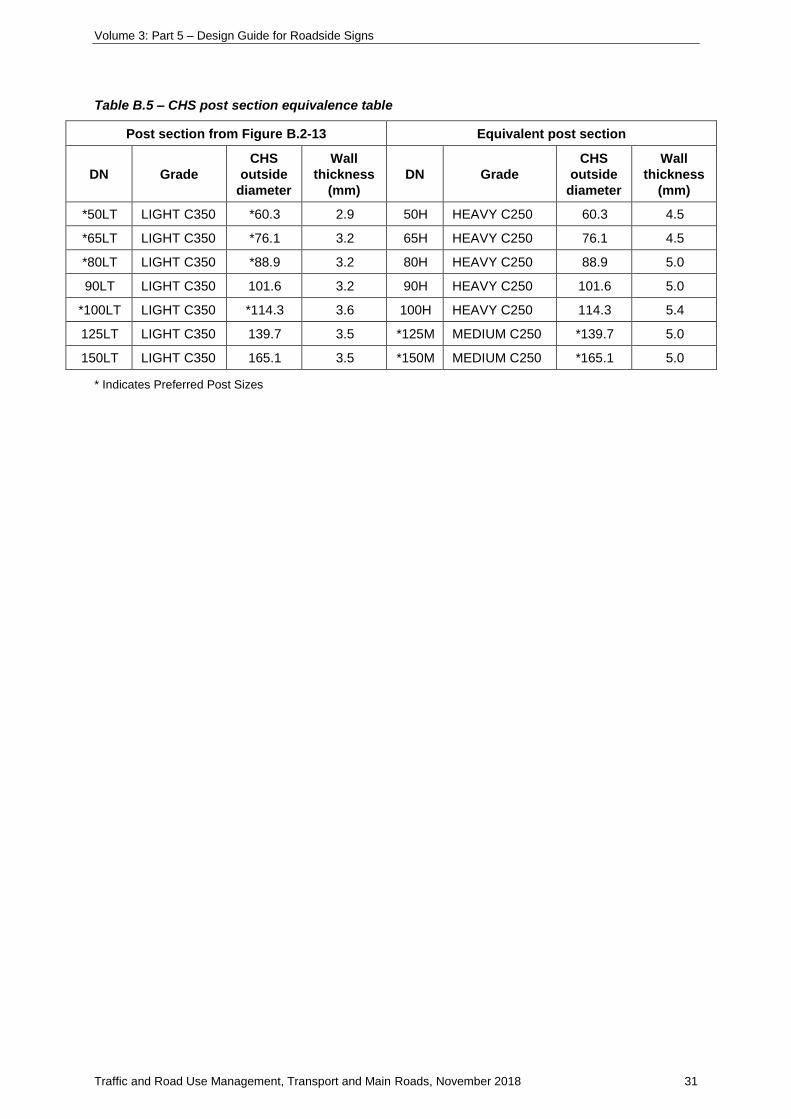
5.3.3 Alternative post section sizes
Table B.5 presents some alternative post section sizes for CHS posts to those called up in
Figures B.2–B.13. The preferred sizes, based on structural efficiency and availability, are highlighted
in Table B.5.
5.3.4 Breakaway supports
The function of breakaway supports is to support the sign under normal wind load conditions, yet fail in
a relatively safe manner when struck by a vehicle.
Volume 3: Part 5 – Design Guide for Roadside Signs
Traffic and Road Use Management, Transport and Main Roads, November 2018 20
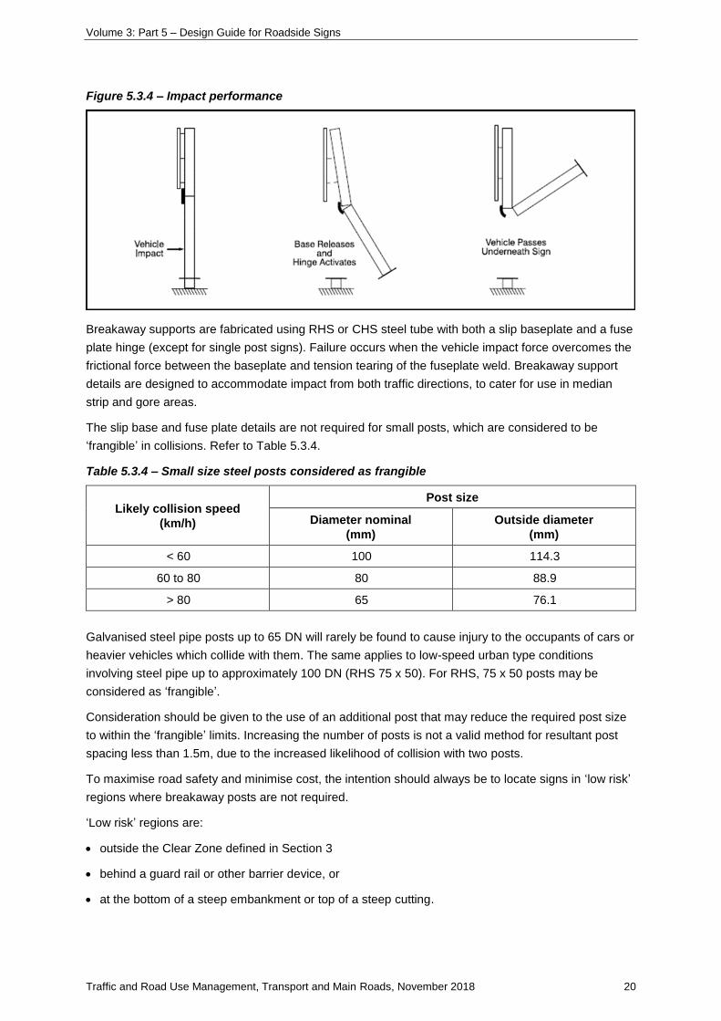
Figure 5.3.4 – Impact performance
Breakaway supports are fabricated using RHS or CHS steel tube with both a slip baseplate and a fuse
plate hinge (except for single post signs). Failure occurs when the vehicle impact force overcomes the
frictional force between the baseplate and tension tearing of the fuseplate weld. Breakaway support
details are designed to accommodate impact from both traffic directions, to cater for use in median
strip and gore areas.
The slip base and fuse plate details are not required for small posts, which are considered to be
‘frangible’ in collisions. Refer to Table 5.3.4.
Table 5.3.4 – Small size steel posts considered as frangible
Likely collision speed
(km/h)
Post size
Diameter nominal
(mm)
Outside diameter
(mm)
< 60 100 114.3
60 to 80 80 88.9
> 80 65 76.1
Galvanised steel pipe posts up to 65 DN will rarely be found to cause injury to the occupants of cars or
heavier vehicles which collide with them. The same applies to low-speed urban type conditions
involving steel pipe up to approximately 100 DN (RHS 75 x 50). For RHS, 75 x 50 posts may be
considered as ‘frangible’.
Consideration should be given to the use of an additional post that may reduce the required post size
to within the ‘frangible’ limits. Increasing the number of posts is not a valid method for resultant post
spacing less than 1.5m, due to the increased likelihood of collision with two posts.
To maximise road safety and minimise cost, the intention should always be to locate signs in ‘low risk’
regions where breakaway posts are not required.
‘Low risk’ regions are:
• outside the Clear Zone defined in Section 3
• behind a guard rail or other barrier device, or
• at the bottom of a steep embankment or top of a steep cutting.
Volume 3: Part 5 – Design Guide for Roadside Signs
Traffic and Road Use Management, Transport and Main Roads, November 2018 21
‘High risk’ regions are those within the Clear Zone defined in Section 4 which are not protected by a
barrier device or steep slope.
Breakaway posts should be avoided where secondary accidents involving the impacting vehicle or
dislodged pole and sign are significant. This is particularly relevant in urban areas where pedestrians
may be struck by falling pieces.
To achieve satisfactory performance of the breakaway supports, the following criteria should be met:
• The clearance of the sign above the ground should be a minimum of 2.1m to avoid penetration of
an impacting vehicle windscreen.
• Proper functioning of the slip base depends on control of clamping pressure between the base
plates produced by bolt tensioning. It is important for the specified bolt torque to be adhered to. The
drawings specify shop assembly of slip bases, to minimise the inaccuracies of torque controlled bolt
tensioning. Pre-assembled slip bases will also enable supports to be plumbed prior to pouring
concrete footings.
• For CHS / RHS posts, the fuse plate hinges have been designed to resist 45% of the post moment
capacity. Signs with panel height (‘B’) greater than 165% of the clearance (‘H’) between the ground
and sign produce a bending moment which exceeds the fuse plate hinge capacity. For these signs
the post size should be increased to the next section size. The allowable panel height is then twice
the clearance.
Breakaway support details are presented in Standard Drawing SD1365 Traffic sign – Traffic sign
support breakaway post details (two or more supports) for CHS / RHS posts
5.4 Fittings
5.4.1 Connection straps
Stiffener rails are generally fixed to supports with circular or rectangular connection straps. Galvanised
steel connection straps for CHS supports (including trusses) and RHS posts are detailed on Standard
Drawing SD1364 Traffic sign – Connection strap and erection cleat details.
5.4.2 Erection cleats
To assist the erection of RHS posts, cleats may be welded to the posts to support the top stiffener rail.
Slotted cleats allow the sign to be levelled, as connection straps are fitted to the remaining stiffener
rails. Erection cleats are detailed on Standard Drawing SD1364 Traffic sign – Connection strap and
erection cleat details.
5.5 Proprietary sign supports
Refer to Traffic and Road Use Management manual Volume 1 Part 10 Section 4.5.3-1.
5.6 Sight boards and other signs at T-intersections
Signs installed parallel to the roadway that include sign stiffeners present a spearing risk to vehicles
that impact them end on. Transport and Main Roads has developed new installation guidelines to
ensure that signs do not spear through vehicle windscreens when impacted. These revised installation
guidelines are given in Standard Drawing SD1452 Traffic sign – Hazard marker installation details.
The Standard Drawing is to be read in conjunction with Appendix E: Design of Sight boards and other
signs at T-intersections.
Volume 3: Part 5 – Design Guide for Roadside Signs
Traffic and Road Use Management, Transport and Main Roads, November 2018 22
6 Storage and handling of signs
6.1 General
In order for the sign to be effective, the surface of the sign must be free from damage, abrasion, dirt,
oil or other markings causing loss of legibility.
These problems are especially severe when dealing with reflective material, since night-time legibility
is directly related to the quality and clarity of the reflective surface.
6.2 General storage
Signs should be stored vertically on edge, either in a rack or in such a way that they are supported
vertically.
Damage is likely to occur to signs stored in contact with each other, or banded together.
Signs stacked tightly together result in pressure points being induced on the reflective sheeting faces,
leading to areas not reflecting.
6.3 Indoor storage
Signs stored indoors may be left in their original transport packaging, provided that the storage area
will be maintained at a constant room temperature and is well ventilated. However, the banding
around any sign should be cut and removed.
If the storage area is a small, non-ventilated area, signs should be unwrapped from their transport
packaging (that is, cardboard, bubble wrap, and so on) and only stored for relatively short periods.
6.4 Outdoor storage
Signs stored outdoors must be unwrapped from their transport packaging and stored upright, on edge,
using wooden battens on the floor, or as vertical supports, or both.
Signs stored outdoors, especially large direction signs, should be stored using a racking system,
providing vertical support, avoiding pressure points on sign faces and allowing adequate air circulation
between sign faces to prevent a build-up of moisture.
6.5 Sign transport
When transporting signs by truck or trailer, it is imperative that signs be securely braced vertically, and
adequately supported and secured to avoid damage due to scuffing, abrasion and load shifting.
Large direction signs should be braced using wooden stiffeners attached to the extrusions at the back
of the sign, and transported with the stiffeners in place to avoid buckling and rivet popping.
6.6 Sign erection
Once signs have been transported to the road site, they should not be laid flat on the ground. Laying
signs flat, can result in damage to the reflective face through direct contact with the ground.
When attaching signs to posts, all connecting bolts should be tightened using offset spanners, not
socket wrenches. The use of offset spanners minimises tool and hand contact with the sign face and
avoids scratching of the surface, as well as allowing the extent of tightening to be observed. Only one
end of the nut and bolt should be tightened, preferable tightened from the rear of the sign.
Tightening from both sides can transfer stress into retroreflective sheeting, with a top film resulting in
permanent pinwheel style wrinkles.
Volume 3: Part 5 – Design Guide for Roadside Signs
Traffic and Road Use Management, Transport and Main Roads, November 2018 23
Avoid over-tightening the connecting bolts, as this can cause specular glare from dimples on the sign
face.
Nylon washers should be used between connecting bolt heads and the sign face, to protect the
reflective sheeting from the twisting action of the bolt heads.
A circle of diameter slightly larger than the bolt head may be scored in the reflective sign face around
the bolt hole, to minimise any fine cracking that may inadvertently occur during bolt tightening.
When erecting large Direction signs, care must be taken to prevent lifting ropes, cables and chains
from contacting the sign surface. These can cause permanent visible damage.
After installation, and before leaving the road site, inspect all signs to see that they have not been
damaged during erection and are free of oil and dirt residue from fingers and tools. A night inspection
will confirm that the surface has not been damaged.
6.7 Sign covering
Covering signs is not recommended. If it is necessary to cover a sign face temporarily after erection,
caution must be exercised, as some coverings may cause permanent damage to the sign face
following exposure to moisture and sunlight.
Porous cloth covers, which are folded over the sign edges and secured to the back of the sign, have
been used successfully for limited periods.
Avoid the use of ropes, wire fasteners or strapping that may abrade the sign surface. Do not apply
tape to the sign face, as sunlight will cause it to bond permanently. Premask or application tape must
be removed before exposure to sunlight.
Do not use paper or plastic covers as heat and moisture entrapment can cause permanent damage to
the reflective sheeting on the sign face.
Consult the sign sheeting manufacturer for advice on how to appropriately cover the sign face to
maintain the product warranty.
6.8 Sign cleaning
For maximum performance, signs should be kept clean and free from dirt, road tar, oil, bituminous
material and mulch. Primarily, this means cleaning the surface of the reflective sheeting – the
essential characteristic of a sign.
A wet, detergent-type, non-abrasive cleaner suitable for high quality paint surfaces is recommended.
The cleaner must also be free of strong aromatic solvents or alcohols and be chemically neutral (that
is, pH of around 7.0). Following use of any cleaning agent, the sign surface must be thoroughly and
immediately rinsed with clean water. In all cleaning operations, care should be taken not to abrade the
sign by use of stiff-bristle brushes or by unnecessary scrubbing.
Normal cleaning procedure:
1) Flush the surface with clean water to remove loose, dirt particles. A squeeze (or triggered) hose
nozzle is convenient for this purpose.
2) Wash the sign face with a rag or sponge using a suitable detergent or commercial cleaner. Wash
thoroughly from the top down. Once suds have been applied, keep a steady stream of water
flowing on the sign face to wash away dirt particles.

Volume 3: Part 5 – Design Guide for Roadside Signs
Traffic and Road Use Management, Transport and Main Roads, November 2018 24
3) Rinse the entire sign face with clean water and allow the sign to drain dry.
4) Take extreme care in cleaning screened sign faces since some cleaning solvents may damage
the screen print.
Use a mild solvent such as mineral spirits for cleaning the sign face. Follow with detergent and water,
then rinse with clean water.
Avoid high-pressure sprayers. Do not direct sprays at sign face edges.
Volume 3: Part 5 – Design Guide for Roadside Signs
Traffic and Road Use Management, Transport and Main Roads, November 2018 25
Appendix A: TraSiS
TraSiS is an electronic implementation of the structural design procedures outlined in this Guide. Our
newest upgrade includes additional features which greatly enhances the sign support structural design
task. It replaces the Sign Design On-Line Software.
The software automates the design procedure and utilises the following inputs:
• sign size
• terrain cross-section
• use of frangible or non-frangible supports
• selection of wind region (in accordance with AS/NZS 1170.2) and
• foundation strength.
A detailed or summary output is provided, and includes:
• the type (CHS / RHS) and number of supports
• support section details (including variable wall thickness for different grades of steel)
• stiffener type, spacing and number of brackets, and
• footing details.
A significant enhancement to the previous version of the software is the addition of a clear zone
module, which calculates clear zone distances based on the following variables:
• Annual Average Daily Traffic (AADT)
• horizontal alignment
• speed environment, and
• terrain cross-section.
The user can consequently specify frangible or non-frangible support, contingent upon the sign
location.
For further information contact Principal Engineer Traffic.
Volume 3: Part 5 – Design Guide for Roadside Signs
Traffic and Road Use Management, Transport and Main Roads, November 2018 26
Appendix B: Design procedure for roadside sign support
Step 1
Determine sign size.
Step 2
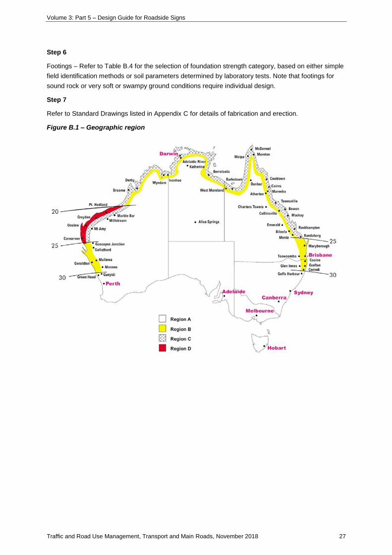
Determine Geographic Wind Region A, B, C – refer Figure B.1.
Note: Region D does not exist in Queensland, however post design charts for Region D have been included in
this Guide to cater for Region C Exposed.
Step 3
Determine if the sign has high or low risk collision exposure (refer Section 5.3.4). Signs with high risk
exposure may require breakaway support details if the posts are not of frangible size. Sign ground
clearance ‘H’ for sign supports with breakaway details should be no lower than 2.1m.
Step 4
Select panel stiffener type and number of supports (N) from Table B.1, based on the sign width. For
modular sign panels, use only Type 2 stiffeners. For the stiffener design and number of posts required
to suit the sign width, the wind region derived from Figure B.1 (Step 2) should be used as these values
have been derived for Exposed Terrain Category 2 conditions.
Maximum sign widths are tabulated for three options of support spacing as discussed in Section 5.3.1.
Option 1 will be most frequently adopted for normal situations to minimise the number of supports.
Option 2 may be adopted where an additional support is required to satisfy the design figures or is
used to achieve ‘frangible’ section size.
Option 3 caters for widely spaced supports (for example, straddling footpaths). Note that for signs of
width less than the limiting values, support spacing may be reduced to less than the ‘standard’ spacing
provided that the maximum stiffener overhang specified in Table B.2 is not exceeded.
Select the number of panel stiffeners from Table B.3. For modular sign panels, use
three stiffeners (Type 2) at 580mm spacing per 1200mm high sign panel module.
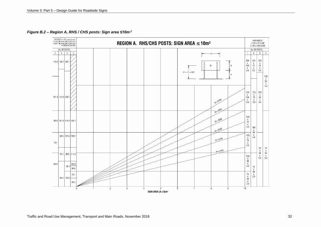
Step 5
Select the support (size and type) from Figure B.2-13 for the appropriate Region A, B, C or D and sign
area. For exposed locations (unshielded Terrain Category 2 in AS/NZS 1170.2) prone to high wind or
where support collapse is more hazardous than normal situations, a Wind Region one step up from
that derived from Figure B.1 (Step 2) should be used (only for post design)for example, use Region C
design charts for Exposed Region B. If no choice of support size is possible for the number of
supports ‘N’ chosen in Step 4, then add an extra support to ‘N’ and choose a support size again from
Figure B.2-13 – refer to discussion in Section 5 of the text on the criteria for selection of support
type (CHS post, RHS post), for example, requirement for breakaway supports, corrosion protection,
erection, structural efficiency, cost, aesthetics.
For breakaway supports, note the limitation on sign panel height relative to sign ground clearance
height. For signs supported by CHS / RHS posts, with sign panel height ‘B’ greater than
1.65 x clearance ‘H’, increase the post size as indicated on Figure B.2-13.
Volume 3: Part 5 – Design Guide for Roadside Signs
Traffic and Road Use Management, Transport and Main Roads, November 2018 27
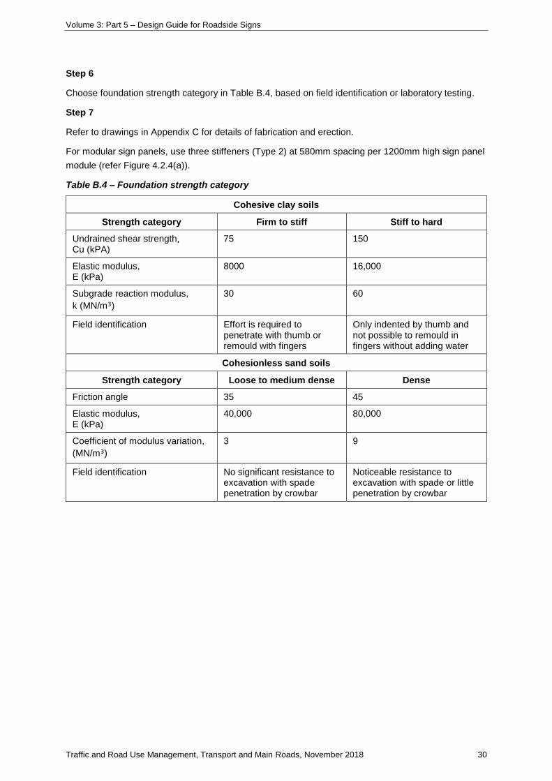
Step 6
Footings – Refer to Table B.4 for the selection of foundation strength category, based on either simple
field identification methods or soil parameters determined by laboratory tests. Note that footings for
sound rock or very soft or swampy ground conditions require individual design.
Step 7
Refer to Standard Drawings listed in Appendix C for details of fabrication and erection.
Figure B.1 – Geographic region
Volume 3: Part 5 – Design Guide for Roadside Signs
Traffic and Road Use Management, Transport and Main Roads, November 2018 28
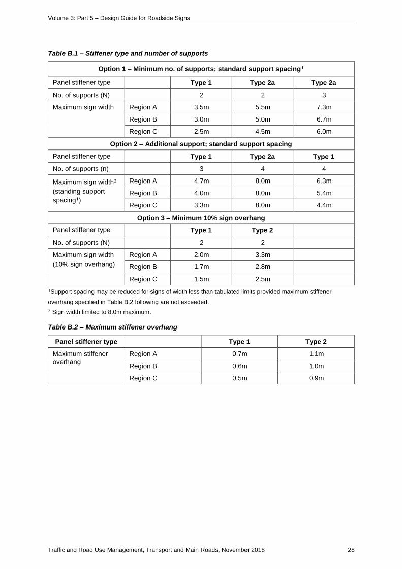
Table B.1 – Stiffener type and number of supports
Option 1 – Minimum no. of supports; standard support spacing¹
Panel stiffener type Type 1 Type 2a Type 2a
No. of supports (N) 2 2 3
Maximum sign width Region A 3.5m 5.5m 7.3m
Region B 3.0m 5.0m 6.7m
Region C 2.5m 4.5m 6.0m
Option 2 – Additional support; standard support spacing
Panel stiffener type Type 1 Type 2a Type 1
No. of supports (n) 3 4 4
Maximum sign width²
(standing support
spacing¹)
Region A 4.7m 8.0m 6.3m
Region B 4.0m 8.0m 5.4m
Region C 3.3m 8.0m 4.4m
Option 3 – Minimum 10% sign overhang
Panel stiffener type Type 1 Type 2
No. of supports (N) 2 2
Maximum sign width
(10% sign overhang)
Region A 2.0m 3.3m
Region B 1.7m 2.8m
Region C 1.5m 2.5m
¹Support spacing may be reduced for signs of width less than tabulated limits provided maximum stiffener
overhang specified in Table B.2 following are not exceeded.
² Sign width limited to 8.0m maximum.
Table B.2 – Maximum stiffener overhang
Panel stiffener type Type 1 Type 2
Maximum stiffener overhang
Region A 0.7m 1.1m
Region B 0.6m 1.0m
Region C 0.5m 0.9m
Volume 3: Part 5 – Design Guide for Roadside Signs
Traffic and Road Use Management, Transport and Main Roads, November 2018 29
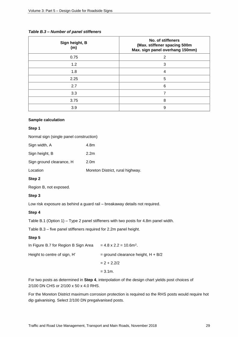
Table B.3 – Number of panel stiffeners
Sign height, B
(m)
No. of stiffeners
(Max. stiffener spacing 500m
Max. sign panel overhang 150mm)
0.75 2
1.2 3
1.8 4
2.25 5
2.7 6
3.3 7
3.75 8
3.9 9
Sample calculation
Step 1
Normal sign (single panel construction)
Sign width, A 4.8m
Sign height, B 2.2m
Sign ground clearance, H 2.0m
Location Moreton District, rural highway.
Step 2
Region B, not exposed.
Step 3
Low risk exposure as behind a guard rail – breakaway details not required.
Step 4
Table B.1 (Option 1) – Type 2 panel stiffeners with two posts for 4.8m panel width.
Table B.3 – five panel stiffeners required for 2.2m panel height.
Step 5
In Figure B.7 for Region B Sign Area = 4.8 x 2.2 = 10.6m².
Height to centre of sign, H’ = ground clearance height, H + B/2
= 2 + 2.2/2
= 3.1m.
For two posts as determined in Step 4, interpolation of the design chart yields post choices of
2/100 DN CHS or 2/100 x 50 x 4.0 RHS.
For the Moreton District maximum corrosion protection is required so the RHS posts would require hot
dip galvanising. Select 2/100 DN pregalvanised posts.
Volume 3: Part 5 – Design Guide for Roadside Signs
Traffic and Road Use Management, Transport and Main Roads, November 2018 30
Step 6
Choose foundation strength category in Table B.4, based on field identification or laboratory testing.
Step 7
Refer to drawings in Appendix C for details of fabrication and erection.
For modular sign panels, use three stiffeners (Type 2) at 580mm spacing per 1200mm high sign panel
module (refer Figure 4.2.4(a)).
Table B.4 – Foundation strength category
Cohesive clay soils
Strength category Firm to stiff Stiff to hard
Undrained shear strength, Cu (kPA)
75 150
Elastic modulus, E (kPa)
8000 16,000
Subgrade reaction modulus,
k (MN/m³)
30 60
Field identification Effort is required to penetrate with thumb or remould with fingers
Only indented by thumb and not possible to remould in fingers without adding water
Cohesionless sand soils
Strength category Loose to medium dense Dense
Friction angle 35 45
Elastic modulus, E (kPa)
40,000 80,000
Coefficient of modulus variation,
(MN/m³)
3 9
Field identification No significant resistance to excavation with spade penetration by crowbar
Noticeable resistance to excavation with spade or little penetration by crowbar
Volume 3: Part 5 – Design Guide for Roadside Signs
Traffic and Road Use Management, Transport and Main Roads, November 2018 31
Table B.5 – CHS post section equivalence table
Post section from Figure B.2-13 Equivalent post section
DN Grade
CHS
outside
diameter
Wall
thickness
(mm)
DN Grade
CHS
outside
diameter
Wall
thickness
(mm)
*50LT LIGHT C350 *60.3 2.9 50H HEAVY C250 60.3 4.5
*65LT LIGHT C350 *76.1 3.2 65H HEAVY C250 76.1 4.5
*80LT LIGHT C350 *88.9 3.2 80H HEAVY C250 88.9 5.0
90LT LIGHT C350 101.6 3.2 90H HEAVY C250 101.6 5.0
*100LT LIGHT C350 *114.3 3.6 100H HEAVY C250 114.3 5.4
125LT LIGHT C350 139.7 3.5 *125M MEDIUM C250 *139.7 5.0
150LT LIGHT C350 165.1 3.5 *150M MEDIUM C250 *165.1 5.0
* Indicates Preferred Post Sizes
Volume 3: Part 5 – Design Guide for Roadside Signs
Traffic and Road Use Management, Transport and Main Roads, November 2018 32
Figure B.2 – Region A, RHS / CHS posts: Sign area ≤10m²

Volume 3: Part 5 – Design Guide for Roadside Signs
Traffic and Road Use Management, Transport and Main Roads, November 2018 33
NOTES: REGION A. RHS/CHS POSTS: SIGN AREA ≤10m²
1. On uneven ground H = height of the tallest post.
2. For signs in exposed locations prone to high wind (unshielded terrain category 2 in AS1170.2) or where
post collapse is more hazardous than normal situations, use charts for next wind region up from that
derived from Figure B.1.
3. For breakaway posts with panel height, B, greater than 1.65 x H, select one size up from that derived on
the graph. Increase support size additionally to any increase required for exposed locations in Note 2.
4. For larger signs, refer also to Figure B.6., Region A. RHS / CHS Posts: sign area ≤28m² and
Figure B.10, Region A. RHS / CHS Posts: sign area ≤40m².
5. LT = light (C350), M = medium (C250). Refer Table B.5.
Volume 3: Part 5 – Design Guide for Roadside Signs
Traffic and Road Use Management, Transport and Main Roads, November 2018 34
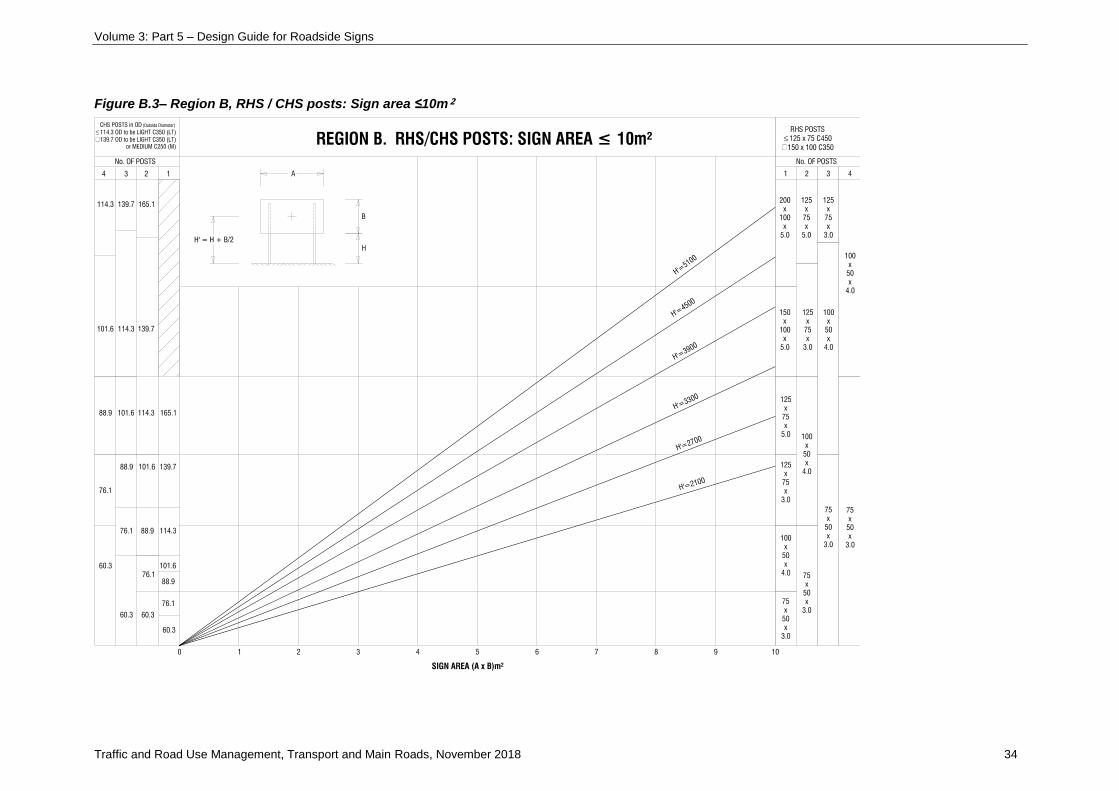
Figure B.3– Region B, RHS / CHS posts: Sign area ≤10m²

Volume 3: Part 5 – Design Guide for Roadside Signs
Traffic and Road Use Management, Transport and Main Roads, November 2018 35
NOTES: REGION B.RHS / CHS POSTS: SIGN AREA ≤10m²
1. On uneven ground H = height of the tallest post.
2. For signs in exposed locations prone to high wind (unshielded terrain category 2 in AS1170.2) or where
post collapse is more hazardous than normal situations, use charts for next wind region up from that
derived from Figure B.1.
3. For breakaway posts with panel height, B, greater than 1.65 x H, select one size up from that derived on
the graph. Increase support size additionally to any increase required for exposed locations in Note 2.
4. For larger signs, refer also to Figure B.7., Region B. RHS / CHS Posts: sign area ≤28m² and Figure
B.11., Region B. RHS / CHS Posts: sign area ≤40m².
5. LT = light (C350), M = medium (C250). Refer Table B.5.
Volume 3: Part 5 – Design Guide for Roadside Signs
Traffic and Road Use Management, Transport and Main Roads, November 2018 36
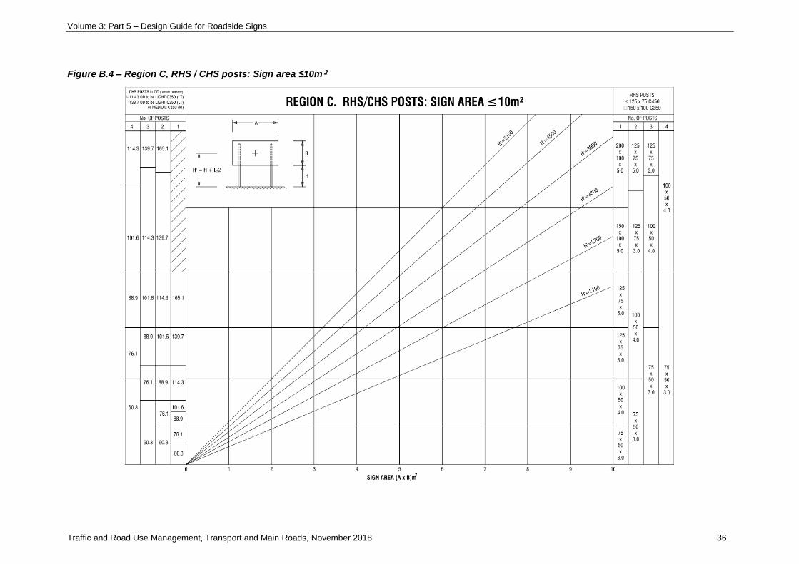
Figure B.4 – Region C, RHS / CHS posts: Sign area ≤10m²

Volume 3: Part 5 – Design Guide for Roadside Signs
Traffic and Road Use Management, Transport and Main Roads, November 2018 37
NOTES: REGION C. RHS / CHS POSTS: SIGN AREA ≤10m²
1. On uneven ground H = height of the tallest post
2. For signs in exposed locations prone to high wind (unshielded terrain category 2 in AS1170.2) or where
post collapse is more hazardous than normal situations, use charts for next wind region up from that
derived from Figure B.1.
3. For breakaway posts with panel height, B, greater than 1.65 x H, select one size up from that derived on
the graph. Increase support size additionally to any increase required for exposed locations in Note 2.
4. For larger signs, refer also to Figure B.8., Region C. RHS / CHS Posts: sign area ≤28m² and Figure
B.12, Region C. RHS / CHS Posts: sign area ≤40m².
5. LT = light (C350), M = medium (C250). Refer Table B.5.
Volume 3: Part 5 – Design Guide for Roadside Signs
Traffic and Road Use Management, Transport and Main Roads, November 2018 38
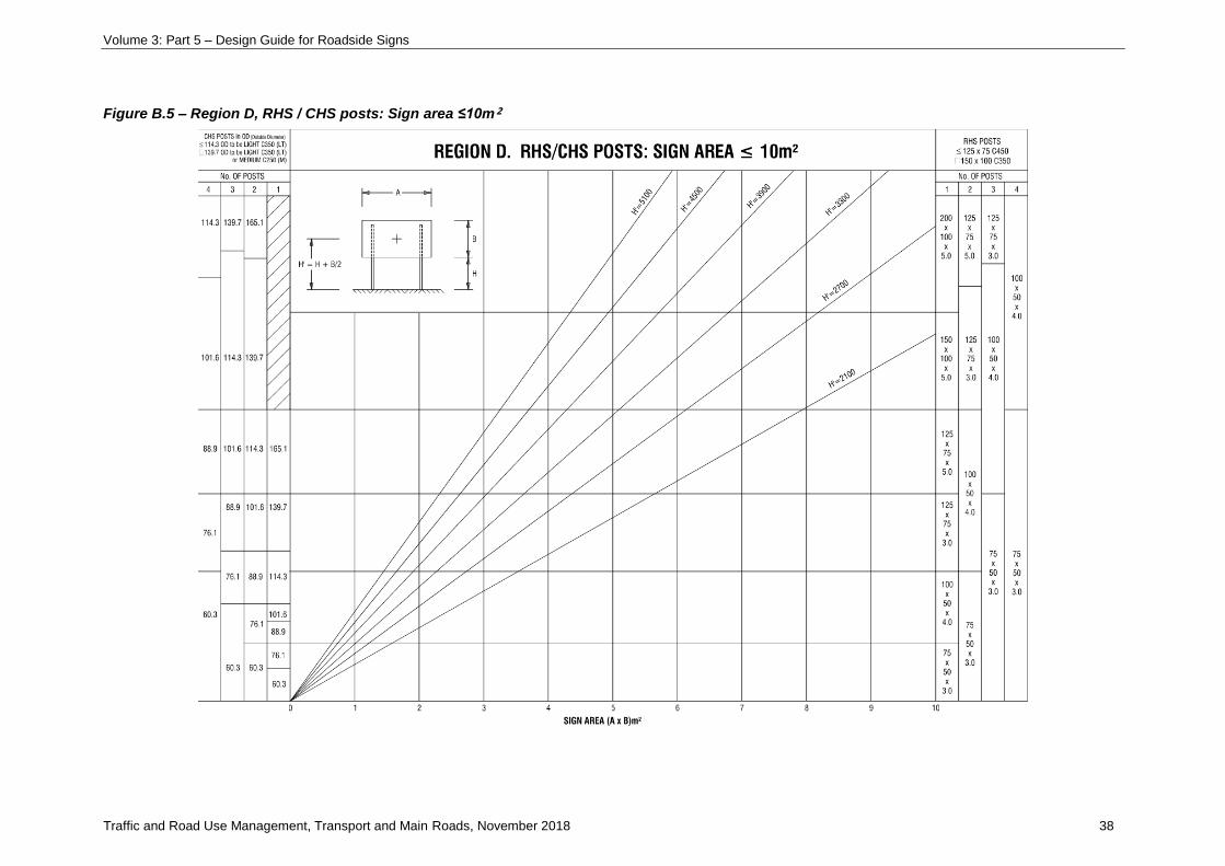
Figure B.5 – Region D, RHS / CHS posts: Sign area ≤10m²

Volume 3: Part 5 – Design Guide for Roadside Signs
Traffic and Road Use Management, Transport and Main Roads, November 2018 39
NOTES: REGION D. RHS / CHS POSTS: SIGN AREA ≤10m²
1. On uneven ground H = height of the tallest post
2. For signs in exposed locations prone to high wind (unshielded terrain category 2 in AS1170.2) or where
post collapse is more hazardous than normal situations, use charts for next wind region up from that
derived from Figure B.1.
3. For breakaway posts with panel height, B, greater than 1.65 x H, select one size up from that derived on
the graph. Increase support size additionally to any increase required for exposed locations in Note 2.
4. For larger signs, refer also to Figure B.9., Region D. RHS / CHS Posts: sign area ≤28m² and
Figure B.13, Region D. RHS / CHS Posts: sign area ≤40m².
5. LT = light (C350), M = medium (C250). Refer Table B.5.
Volume 3: Part 5 – Design Guide for Roadside Signs
Traffic and Road Use Management, Transport and Main Roads, November 2018 40
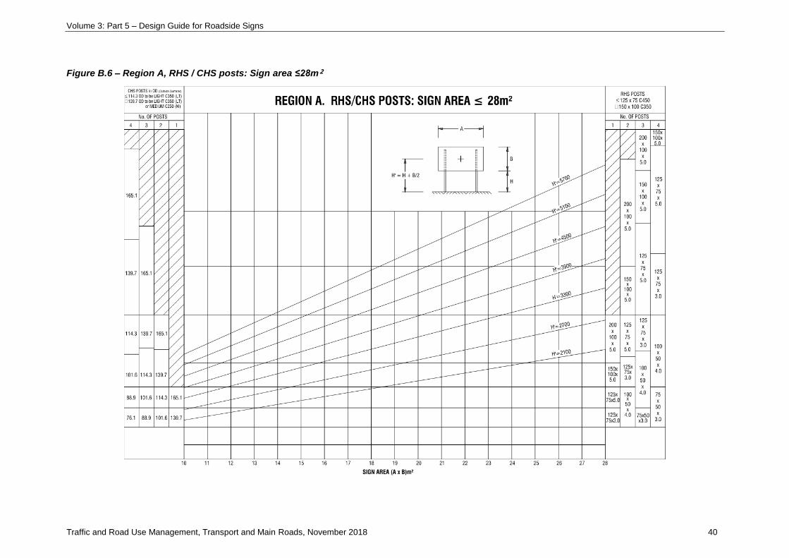
Figure B.6 – Region A, RHS / CHS posts: Sign area ≤28m²

Volume 3: Part 5 – Design Guide for Roadside Signs
Traffic and Road Use Management, Transport and Main Roads, November 2018 41
NOTES: REGION A. RHS / CHS POSTS: SIGN AREA ≤28m²
1. On uneven ground H = height of the tallest post
2. For signs in exposed locations prone to high wind (unshielded terrain category 2 in AS1170.2) or where
post collapse is more hazardous than normal situations, use charts for next wind region up from that
derived from Figure B.1.
3. For breakaway posts with panel height, B, greater than 1.65 x H, select one size up from that derived on
the graph. Increase support size additionally to any increase required for exposed locations in Note 2.
4. For larger signs, refer also to Figure B.2., Region A. RHS / CHS Posts: sign area ≤10m² and
Figure B.10., Region A. RHS / CHS Posts: sign area ≤40m² respectively.
5. LT = light (C350), M = medium (C250). Refer Table B.5.
Volume 3: Part 5 – Design Guide for Roadside Signs
Traffic and Road Use Management, Transport and Main Roads, November 2018 42
Figure B.7 – Region B, RHS / CHS posts: Sign area ≤28m²

Volume 3: Part 5 – Design Guide for Roadside Signs
Traffic and Road Use Management, Transport and Main Roads, November 2018 43
NOTES: REGION B. RHS / CHS POSTS: SIGN AREA ≤28m²
1. On uneven ground H = height of the tallest post
2. For signs in exposed locations prone to high wind (unshielded terrain category 2 in AS1170.2) or where
post collapse is more hazardous than normal situations, use charts for next wind region up from that
derived from Figure B.1.
3. For breakaway posts with panel height, B, greater than 1.65 x H, select one size up from that derived on
the graph. Increase support size additionally to any increase required for exposed locations in Note 2.
4. For larger signs, refer also to Figure B.3., Region B. RHS / CHS Posts: sign area ≤10m² and
Figure B.11., Region B. RHS / CHS Posts: sign area ≤40m² respectively.
5. LT = light (C350), M = medium (C250). Refer Table B.5.
Volume 3: Part 5 – Design Guide for Roadside Signs
Traffic and Road Use Management, Transport and Main Roads, November 2018 44
Figure B.8 – Region C, RHS / CHS posts: Sign area ≤28m²

Volume 3: Part 5 – Design Guide for Roadside Signs
Traffic and Road Use Management, Transport and Main Roads, November 2018 45
NOTES: REGION C. RHS / CHS POSTS: SIGN AREA ≤28m²
1. On uneven ground H = height of the tallest post
2. For signs in exposed locations prone to high wind (unshielded terrain category 2 in AS1170.2) or where
post collapse is more hazardous than normal situations, use charts for next wind region up from that
derived from Figure B.1.
3. For breakaway posts with panel height, B, greater than 1.65 x H, select one size up from that derived on
the graph. Increase support size additionally to any increase required for exposed locations in Note 2.
4. For larger signs, refer also to Figure B.4., Region C. RHS / CHS Posts: sign area ≤10m² and
Figure B.12., Region C. RHS / CHS Posts: sign area ≤40m² respectively.
5. LT = light (C350), M = medium (C250). Refer Table B.5.
Volume 3: Part 5 – Design Guide for Roadside Signs
Traffic and Road Use Management, Transport and Main Roads, November 2018 46
Figure B.9 – Region D, RHS / CHS posts: Sign area ≤28m²

Volume 3: Part 5 – Design Guide for Roadside Signs
Traffic and Road Use Management, Transport and Main Roads, November 2018 47
NOTES: REGION D. RHS / CHS POSTS: SIGN AREA ≤28m²
1. On uneven ground H = height of the tallest post
2. For signs in exposed locations prone to high wind (unshielded terrain category 2 in AS1170.2) or where
post collapse is more hazardous than normal situations, use charts for next wind region up from that
derived from Figure B.1.
3. For breakaway posts with panel height, B, greater than 1.65 x H, select one size up from that derived on
the graph. Increase support size additionally to any increase required for exposed locations in Note 2.
4. For larger signs, refer also to Figure B.5., Region D. RHS / CHS Posts: sign area ≤10m² and
Figure B.13., Region D. RHS/CHS Posts: sign area ≤40m² respectively.
5. LT = light (C350), M = medium (C250). Refer Table B.5.
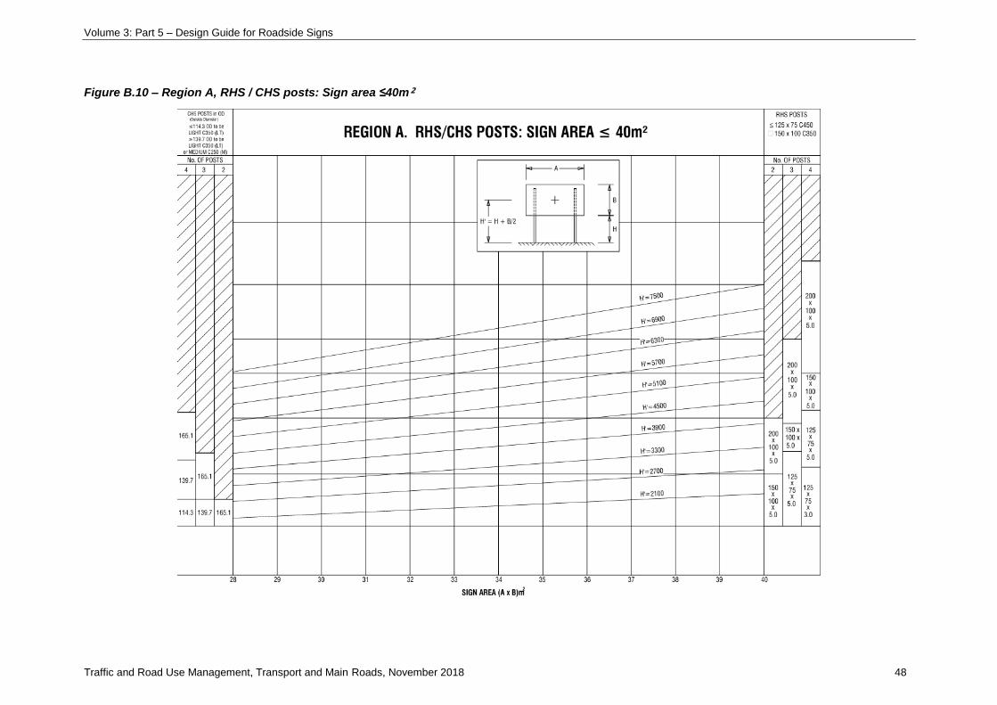
Volume 3: Part 5 – Design Guide for Roadside Signs
Traffic and Road Use Management, Transport and Main Roads, November 2018 48
Figure B.10 – Region A, RHS / CHS posts: Sign area ≤40m²

Volume 3: Part 5 – Design Guide for Roadside Signs
Traffic and Road Use Management, Transport and Main Roads, November 2018 49
NOTES: REGION A. RHS / CHS POSTS: SIGN AREA ≤40m²
1. On uneven ground H = height of the tallest post
2. For signs in exposed locations prone to high wind (unshielded terrain category 2 in AS1170.2) or where
post collapse is more hazardous than normal situations, use charts for next wind region up from that
derived from Figure B.1.
3. For breakaway posts with panel height, B, greater than 1.65 x H, select one size up from that derived on
the graph. Increase support size additionally to any increase required for exposed locations in Note 2.
4. For smaller signs, refer also to Figure B.2., Region A. RHS / CHS Posts: sign area ≤10m² and
Figure B.6., Region A. RHS / CHS Posts: sign area ≤28m².
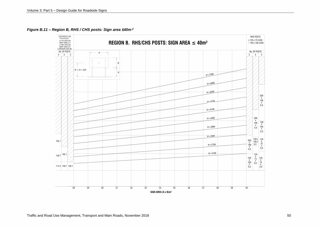
Volume 3: Part 5 – Design Guide for Roadside Signs
Traffic and Road Use Management, Transport and Main Roads, November 2018 50
Figure B.11 – Region B, RHS / CHS posts: Sign area ≤40m²

Volume 3: Part 5 – Design Guide for Roadside Signs
Traffic and Road Use Management, Transport and Main Roads, November 2018 51
NOTES: REGION B. RHS / CHS POSTS: SIGN AREA ≤40m²
1. On uneven ground H = height of the tallest post
2. For signs in exposed locations prone to high wind (unshielded terrain category 2 in AS1170.2) or where
post collapse is more hazardous than normal situations, use charts for next wind region up from that
derived from Figure B.1.
3. For breakaway posts with panel height, B, greater than 1.65 x H, select one size up from that derived on
the graph. Increase support size additionally to any increase required for exposed locations in Note 2.
4. For smaller signs, refer also to Figure B.3., Region B. RHS / CHS Posts: sign area ≤10m² and
Figure B.7., Region B RHS / CHS Posts: sign area ≤28m².
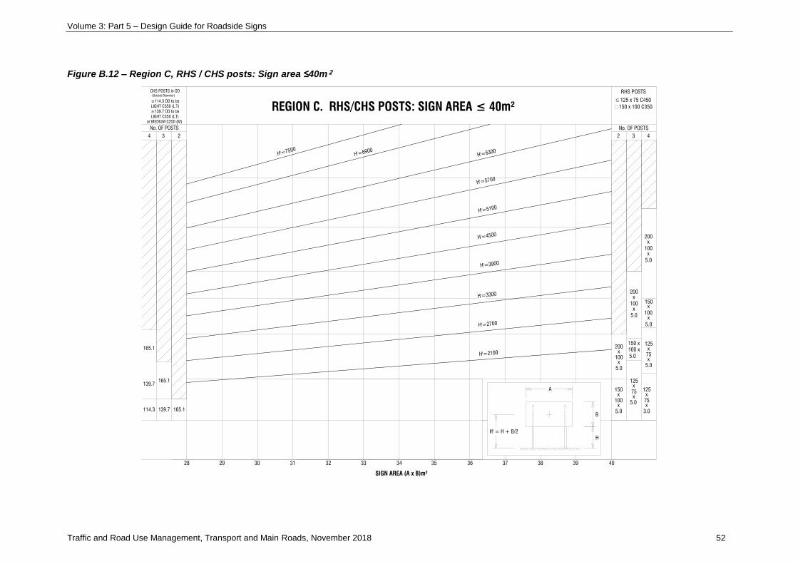
Volume 3: Part 5 – Design Guide for Roadside Signs
Traffic and Road Use Management, Transport and Main Roads, November 2018 52
Figure B.12 – Region C, RHS / CHS posts: Sign area ≤40m²

Volume 3: Part 5 – Design Guide for Roadside Signs
Traffic and Road Use Management, Transport and Main Roads, November 2018 53
NOTES: REGION C. RHS / CHS POSTS: SIGN AREA ≤40m²
1. On uneven ground H = height of the tallest post
2. For signs in exposed locations prone to high wind (unshielded terrain category 2 in AS1170.2) or where
post collapse is more hazardous than normal situations, use charts for next wind region up from that
derived from Figure B.1.
3. For breakaway posts with panel height, B, greater than 1.65 x H, select one size up from that derived on
the graph. Increase support size additionally to any increase required for exposed locations in Note 2.
4. For smaller signs, refer also to Figure B.4., Region C. RHS / CHS Posts: sign area ≤10m² and
Figure B.8., Region C. RHS / CHS Posts: sign area ≤28m².
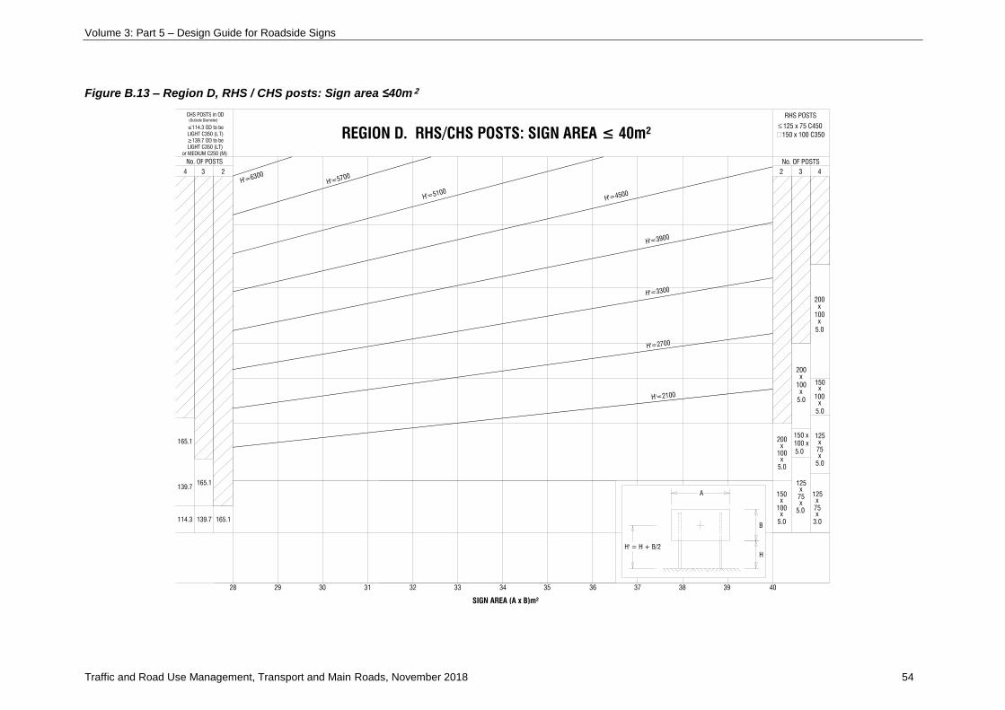
Volume 3: Part 5 – Design Guide for Roadside Signs
Traffic and Road Use Management, Transport and Main Roads, November 2018 54
Figure B.13 – Region D, RHS / CHS posts: Sign area ≤40m²

Volume 3: Part 5 – Design Guide for Roadside Signs
Traffic and Road Use Management, Transport and Main Roads, November 2018 55
NOTES: REGION D. RHS / CHS POSTS: SIGN AREA ≤40m²
1. On uneven ground H = height of the tallest post
2. For signs in exposed locations prone to high wind (unshielded terrain category 2 in AS1170.2) or where
post collapse is more hazardous than normal situations, use charts for next wind region up from that
derived from Figure B.1.
3. For breakaway posts with panel height, B, greater than 1.65 x H, select one size up from that derived on
the graph. Increase support size additionally to any increase required for exposed locations in Note 2.
4. For smaller signs, refer also to Figure B.5., Region D. RHS / CHS Posts: sign area ≤10m² and
Figure B.9., Region D. RHS / CHS Posts: sign area ≤28m².
Volume 3: Part 5 – Design Guide for Roadside Signs
Traffic and Road Use Management, Transport and Main Roads, November 2018 56
Appendix C: Standard Drawings
• Standard Drawing SD1363 Traffic sign – Multiple traffic sign support – Standard and
breakaway posts – Drawings 1 of 2 and 2 of 2
• Standard Drawing SD1364 Traffic sign – Connection strap and erection cleat details
• Standard Drawing SD1365 Traffic Sign – Traffic sign support breakaway post details (two or
more supports)
• Standard Drawing SD1366 Traffic sign Traffic sign support detail truss type breakaway
• Standard Drawing SD1367 Traffic Sign – Traffic sign support detail truss type breakaway
bracing details
• Standard Drawing SD1368 Traffic sign – Single traffic sign support
• Standard Drawing SD1452 Traffic sign – Hazard marker installation details for rehabilitation of
existing (Sheet 1 of 3)
• Standard Drawing SD1452 Traffic sign – Hazard marker installation details for new
installation (Sheet 2 of 3)
• Standard Drawing SD1452 Traffic sign – Hazard marker connection details (Sheet 3 of 3)
Volume 3: Part 5 – Design Guide for Roadside Signs
Traffic and Road Use Management, Transport and Main Roads, November 2018 57
Appendix D: Development of the 2018 Design Guide
The 2018 Design Guide for Roadside Signs has been revised from the 2001 Design Guide. The
primarily structural revisions are:
• use of the current Standard, AS/NZS 1170.2-2011 Wind Actions terminology, with an appropriate
pressure reduction factor used to derive similar support structure sizes to the 2001 design
methodology; the reduction factor is subject to a Department of Transport and Main
Roads-approved design exemption, and
• removal of Trusses as a support option.
D1 Background
The 2001 Guide was developed from the 1996 draft edition which was released in response to
negative feedback from users of the 1991 Guide and a perceived deficiency in the treatment and
explanation of breakaway posts. This feedback was confirmed in a user survey, with many
respondents indicating that the steel posts and footings derived from the 1991 Guide to be excessive
to that required to support road signs. The survey indicated that users were adopting alternatives to
use of the Guide including:
• factoring of the 1991 Guide Figure B2 to give less conservative post sizes
• use of the pre-1987 Guide drawing TC9043, which uses steel yield as the allowable stress, 25-year
return period, old shape factor of 1.2 and no cyclone factor, and
• avoidance of breakaway posts by only using CHS for which there are no breakaway details.
Users indicated a strong preference for accepting that some signs may be blown over in a cyclone or
storm rather than using larger posts which present an increased traffic hazard. It was seen to be a
relatively simple operation to bend smaller posts (particularly CHS) back into position if blown over.
The survey also indicated a preference for use of CHS posts (as discussed further) for which the
range of sizes and details are limited in the 1991 Guide.
A limited field survey of road signs in Metropolitan District indicated that users are adopting post sizes
and details in variance to those prescribed by the Guide.
The incorporation of a rational method in accordance with Australian Standards for derivation of
acceptable post sizes was considered critical for the success of the revised Guide.
Since 1996 there has been multiple cyclonic weather conditions experienced in far north Queensland,
including the Category 5 Cyclone Yasi in 2011. Following these high wind events, there has been no
reported occurrences of widespread sign face detachment; most signs that did fail, failed in the
desired failure mechanism of post bending failure.
D2 Design wind pressure
D2.1 Previous Guide
The 1996 / 2001 Guides were based on a reduced structural importance multiplier, Mi. The structural
importance multiplier, Mi in AS/NZS 1170.2-1989 represented a probability of exceedance of a design
wind speed. For Mi = 1.0, there is a 5% chance of exceedance of the ultimate wind speed in a 50-year
return period. The adopted importance multiplier which related to the maximum acceptable chance of
exceedance was Mi = 0.75. For Mi = 0.75, the chance of exceedance in 50-year and one-year return
Volume 3: Part 5 – Design Guide for Roadside Signs
Traffic and Road Use Management, Transport and Main Roads, November 2018 58
periods is 96% and 6.5% respectively. That is, every year there is a 6.5% chance of the sign
experiencing its design ultimate wind speed.
AS/NZS 1170.2 allows a directionality factor of 0.95 on wind speed in non-cyclonic regions for
overturning calculations to account for the reduced probability of the design wind speed occurring in
the critical direction for a structure. This directionality factor was reduced further to 0.9 to account for
the fact that (in non-cyclonic regions) the design wind speed will generally come from one direction for
a particular locality. As the design wind speed for a particular locality comes from one direction,
depending on the road orientation, some signs will never experience the design wind speed in their
critical direction. Viewing the performance of the road sign structures globally, rather than designing
for directionality in each individual sign, justified the use of the reduced directionality factor of 0.9.
Support sizes were chosen based on wind loads at locations which were assumed to be in the general
sheltered terrain categories, TC3 and TC4. For Exposed locations, the method required use of
one wind region higher; for example, for an exposed (TC2) location in Region B, Region C design
charts were to be used.
A safe failure mode was achieved by post bending prior to stiffener rails and panel fixing failure to
prevent flying sign panels presenting a hazard. Stiffener rails were designed for the maximum design
wind pressure with an additional safety factor of 1.67 to ensure signs are not blown off before the
poles bent over. The factor 1.67 derived from the combination of load factor and capacity reduction
factor on the pole (1.5/0.9).
D2.2 2018 Design Guide
The proposed method to be adopted in the revised Design Guide is based on the following:
Safe failure mode
The design strategy is based on a safe failure mode of support post yielding and bending prior to
failure of the sign face and its attachment to the posts. To ensure that signs are not blown off before
the poles bend, aluminium stiffener rails and sign face are designed to accommodate peak edge
pressures generated by the critical 45 degree wind approach angle, Terrain Category 2 (fully exposed)
and with an additional safety factor of 1.5 applied to the post design pressure.
Importance level
Importance Level 1 in accordance with AS/NZS1170:0-2002 Appendix F is used, based on ‘small or
moderate’ economic consequence and safe failure mode with failure unlikely to endanger human life.
A design working life of 25 years is considered appropriate and this yields an annual probability of
exceedance of 1 in 100 (1/100) for cyclonic and non-cyclonic wind speed.
Pressure reduction factor
A pressure reduction factor, R = 0.5, is applied to the ultimate support post design pressure derived in
accordance with AS/NZS 1170.2-2011. This factor is applied to the resultant pressure derived from
wind speed and pressure co-efficient. The R = 0.5 reduction factor accounts for both wind speed
increase and the increased force on the windward post under oblique wind directions which was not
accounted for in the 1993 Guide. The effective design eccentricity is taken as e = 0.1b (Table D2(B) in
AS/NZS 1170.2-2011) resulting in a 33% increase in force on the windward post. This eccentricity,
which is less than the maximum eccentricity of e = 0.2b for wind at 45 degrees is considered
applicable to the very flexible sign support structures which will distribute uneven loads.
Volume 3: Part 5 – Design Guide for Roadside Signs
Traffic and Road Use Management, Transport and Main Roads, November 2018 59
Using the formula in AS/NZS 1170.2-2011. Table 3.1 which derives regional wind
speeds: VR = 106 - 92R - 0.1 for Region B (for example) – the wind speed which is a reduction
of (2/1.33) 0.5 on the regional 100-year return wind speed of V100 = 48m/s is 39m/s. For
VR = 39m/s = 106 - 92R - 0.1, R = 26.7-year return period, equivalent to 3.75% annual probability of
exceedance. The Region B design pressure is then calculated as
p = 0.0006 * (39 * 0.83 * 0.95) 2 * 1.5 = 0.86kPa.
For wind speed reduction also accommodating the 1.33 windward pole pressure factor, the wind
speed which is a reduction of (2) 0.5 on the regional 100-year return wind speed of V100 = 48m/s is
34m/s. For VR = 34m/s = 106 - 92R - 0.1, R = 12.7-year return period, equivalent to 7.8 % annual
probability of exceedance. The Region B design pressure is then calculated as
p = 0.0006 * (34 * 0.83 * 0.95) 2 * 1.5 * 1.33 = 0.86kPa.
D3 Design method
D3.1 Stiffener arrangement
The number of posts and stiffener type, spacing and number are selected directly for a given sign size.
Variations to the standard post spacing are catered for by an additional table for widely spaced posts
and a table of maximum stiffener overhangs for reduced post spacing.
Sign width limits are tabulated for the four geographic regions to be consistent with the post design
method.
D3.2 Post size and selection
A graphical method of post selection has been maintained in the new Guide, similar in format to the
Australian Standard AS1742.2-2009. Each geographic region is catered for with a separate set of
tables for clarity and ease of use. The post size is chosen directly off the table for a given sign size,
height and number of posts. An option is given for either CHS or RHS posts for the smaller signs.
Guidance for choice of CHS or RHS is presented in the text.
A section equivalence table has been added to the Guide for CHS posts to offer alternative
Grade C250 section sizes to those Grade C350 section sizes called up by the Guide.
D4 Drawings
Standard Drawing SD1363 Traffic sign – Multiple traffic sign support – Standard and breakaway posts
– Drawings 1 of 2 and 2 of 2, Standard Drawing SD1364 Traffic sign – Connection strap and erection
cleat details and Standard Drawing SD1365 Traffic Sign – Traffic sign support breakaway post
details (two or more supports) have superseded existing Standard Drawings SD1360, SD1361 and
SD1362. The Standard Drawings have been organised to cater for breakaway and non-breakaway
supports together, rather than providing separate drawings with repeated details.
This assists in providing a less fragmented document. The slip base and fuseplate hinge are simply
additional details incorporated as required onto the standard post.
The revised drawings also present CHS and RHS posts together rather than on separate drawings
with inconsistent specifications.
Specification of clearances, heights, orientation etc. are referred to the Manual of Uniform Traffic
Control Devices rather than trying to incorporate some of this information on the structural drawings.
Volume 3: Part 5 – Design Guide for Roadside Signs
Traffic and Road Use Management, Transport and Main Roads, November 2018 60
Standard Drawing SD1295 Sign – Fingerboard, geographical feature and street name signs bracket
details has not yet been altered while Standard Drawings SD1296, SD1297, SD1298, SD1299,
SD1300 and SD1360 have been withdrawn.
D5 AS4100 Steel Structures Code
The sign support posts have been designed in accordance with the limit state steel code
AS4100-1998. Ultimate design wind speeds were used.
D6 Breakaway posts
D6.1 Risk
‘Low risk’ is defined as outside the clear zone and ‘high risk’ is within half the clear zone distance of
the traffic lane edge of the road.
D6.2 Frangible posts
The size of posts considered to be frangible has not been modified from the 1996 / 2001 Design
Guides. Crash testing of longitudinal sight boards in 2016/17 commissioned by NSW Centre for Road
Safety and Queensland’s Department of Transport and Main Roads has confirmed that 65NB posts
are readily frangible for vehicle speeds >80km/hr which is consistent with recommendations in the
2001 Design Guide. The AS174.2-2009 recommendation for 50NB for speeds >80km/hr is considered
to be overly conservative.
D6.3 Criteria
Criteria for satisfactory performance of breakaway posts is included in the Guide.
The American Association of State Highway and Transportation Officials (AASHTO) Roadside Design
Guide criterion for 2.1m clearance has been incorporated. The AASHTO criteria on post weight will be
satisfied for all posts in the range of the Guide.
A minimum post spacing of 1.5m has been recommended as the limit for use of additional posts of
‘frangible’ size to support signs in ‘high risk’ zones. The AASHTO Guide considers all posts in a swept
path of 2.1m when checking that the weight of posts is less than the recommended limit.
Design in accordance with the AASHTO Guide would therefore require consideration of the combined
resistance to impact of all posts within a 2.1m width, rather than designation of individual posts as
frangible if smaller than the recommended size. Adoption of a 2.1m swept path would disqualify many
signs from use of ‘frangible’ post support. The 1.5m minimum spacing limit is proposed as an
acceptable, less conservative, limit for consideration of impact on posts in isolation.
A limit on sign height relative to clearance has been incorporated to ensure that the fuse plate moment
capacity is not exceeded under the design wind speed. The current fuse plate detail appears to be
designed for the post capacity which relates to a sign height not greater than the clearance. Many
existing signs will not conform to this criterion and will therefore potentially fail at the fuse plate at less
than the design wind speed.
D6.4 Post type
Breakaway post details have been incorporated for both CHS and RHS posts.
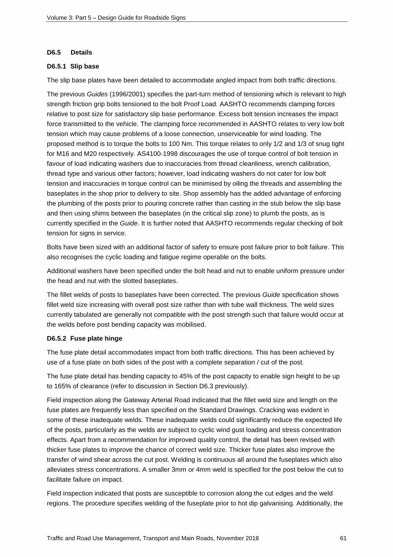
Volume 3: Part 5 – Design Guide for Roadside Signs
Traffic and Road Use Management, Transport and Main Roads, November 2018 61
D6.5 Details
D6.5.1 Slip base
The slip base plates have been detailed to accommodate angled impact from both traffic directions.
The previous Guides (1996/2001) specifies the part-turn method of tensioning which is relevant to high
strength friction grip bolts tensioned to the bolt Proof Load. AASHTO recommends clamping forces
relative to post size for satisfactory slip base performance. Excess bolt tension increases the impact
force transmitted to the vehicle. The clamping force recommended in AASHTO relates to very low bolt
tension which may cause problems of a loose connection, unserviceable for wind loading. The
proposed method is to torque the bolts to 100 Nm. This torque relates to only 1/2 and 1/3 of snug tight
for M16 and M20 respectively. AS4100-1998 discourages the use of torque control of bolt tension in
favour of load indicating washers due to inaccuracies from thread cleanliness, wrench calibration,
thread type and various other factors; however, load indicating washers do not cater for low bolt
tension and inaccuracies in torque control can be minimised by oiling the threads and assembling the
baseplates in the shop prior to delivery to site. Shop assembly has the added advantage of enforcing
the plumbing of the posts prior to pouring concrete rather than casting in the stub below the slip base
and then using shims between the baseplates (in the critical slip zone) to plumb the posts, as is
currently specified in the Guide. It is further noted that AASHTO recommends regular checking of bolt
tension for signs in service.
Bolts have been sized with an additional factor of safety to ensure post failure prior to bolt failure. This
also recognises the cyclic loading and fatigue regime operable on the bolts.
Additional washers have been specified under the bolt head and nut to enable uniform pressure under
the head and nut with the slotted baseplates.
The fillet welds of posts to baseplates have been corrected. The previous Guide specification shows
fillet weld size increasing with overall post size rather than with tube wall thickness. The weld sizes
currently tabulated are generally not compatible with the post strength such that failure would occur at
the welds before post bending capacity was mobilised.
D6.5.2 Fuse plate hinge
The fuse plate detail accommodates impact from both traffic directions. This has been achieved by
use of a fuse plate on both sides of the post with a complete separation / cut of the post.
The fuse plate detail has bending capacity to 45% of the post capacity to enable sign height to be up
to 165% of clearance (refer to discussion in Section D6.3 previously).
Field inspection along the Gateway Arterial Road indicated that the fillet weld size and length on the
fuse plates are frequently less than specified on the Standard Drawings. Cracking was evident in
some of these inadequate welds. These inadequate welds could significantly reduce the expected life
of the posts, particularly as the welds are subject to cyclic wind gust loading and stress concentration
effects. Apart from a recommendation for improved quality control, the detail has been revised with
thicker fuse plates to improve the chance of correct weld size. Thicker fuse plates also improve the
transfer of wind shear across the cut post. Welding is continuous all around the fuseplates which also
alleviates stress concentrations. A smaller 3mm or 4mm weld is specified for the post below the cut to
facilitate failure on impact.
Field inspection indicated that posts are susceptible to corrosion along the cut edges and the weld
regions. The procedure specifies welding of the fuseplate prior to hot dip galvanising. Additionally, the
Volume 3: Part 5 – Design Guide for Roadside Signs
Traffic and Road Use Management, Transport and Main Roads, November 2018 62
post splice is specified to be full contact which should enable the galvanising to seal across the cut.
The fuse plate is welded all around to effectively seal behind the plate such that the whole assembly
can be protected with the hot dip galvanising.
D7 Posts types
The user survey indicated a strong preference for the use of CHS posts rather than RHS. Advantages
identified with CHS are pregalvanised; availability; cheaper (availability in 6.5m lengths compared with
8m for RHS leading to less wastage is one consideration); readily cut and capped on site with pipe
cutters so less tolerance on post length required; less requirement for alignment with sign face;
availability of fittings; and more easily pushed back to alignment if bent over by wind or vehicle
collision.
90 NB is included in the graphs but is not readily available.
RHS posts have been retained with further explanation to when they may be economical. The
structural efficiency and hence potential cost saving has been identified particularly with the use of
pregalvanised RHS. Tubemakers Duragal is only 3% more expensive than black steel and is rated at
Grade 450. The cost of a Grade 450 pregalvanised RHS post is half the cost of the equivalent
strength CHS. The use of pregalvanised RHS (without further hot dip galvanising) is limited to regions
of low corrosion potential due to the reduced thickness of zinc coating (100g/m² compared to 300g/m²
for hot dip galvanising).
RHS posts may also be cost effective for breakaway posts where the advantage of
pregalvanised CHS is lost with the requirement on hot dip galvanising the breakaway posts after
fabrication.
D8 Stiffener rails
A maximum stiffener spacing of 500mm with overhang of 150mm is used.
The Guide specifies a pole spacing ratio of 0.15 / 0.35 / 0.35 / 0.15 and 0.2 / 0.6 / 0.2 for three and
two pole signs respectively. These ratios balance both pole load and stiffener support and span
moment.
D9 Single post signs
The 1996/2001 Guides included a new system and detail to accommodate the common situation of
signs wider than 950mm, which cannot be supported on two posts; for example, on a narrow median
strip. The sign panel is stiffened and fixed to a single post with 6mm steel brackets. The steel brackets
are screwed into the post to prevent rotation.
D10 Footings
D10.1 Design strategy
The Guide specifies footings sizes for two soil strength categories for both cohesive and non-cohesive
soils. Cohesive and non-cohesive soils are distinguished between, due to different mechanisms of soil
resistance and hence design formulae. For non-cohesive soils, lateral resistance is dependent on
overburden stress, so footings are deeper and narrower than for cohesive soils.
Table B.4 in the Appendix B design procedure enables choice of appropriate foundation strength
category by use of either simple field identification procedures or parameters derived by laboratory
testing.
Volume 3: Part 5 – Design Guide for Roadside Signs
Traffic and Road Use Management, Transport and Main Roads, November 2018 63
D10.1.1 Cohesive soils
The footings for cohesive soils are designed using the method suggested by Coyle and Bierschwale,
Design of Rigid Shafts in Clay for Lateral Load, ASCE J Geotech Eng, Vol 109, No 9, 1983. This
method determines the ultimate lateral load that can be applied to a pile for a limiting deflection
criteria. A pile rotation of two degrees is considered to be the serviceable limit beyond which loosening
of the pile may occur due to plastic deformation of the soil. This method produces less conservative
results than other methods which limit soil pressure.
D10.1.2 Non-cohesive soils
The SAA Piling Code (AS2159-1978) was used for design of footings in non-cohesive soils with an
appropriately chosen Factor of Safety on ultimate lateral resistance.
D10.1.3 Other soils
The Guide highlights the requirement for special design of footings in very soft or swampy soils and
sound rock.
D10.1.4 Details
The footings have been designed without reinforcement by utilising the combined bending resistance
of the embedded post and unreinforced concrete pier.
The diameter and depth of piers have been chosen with consideration to minimising pier depth.
D11 Modular sign panels
Modular sign panels have been included in the Guide to facilitate the installation of larger signs. A
sketch which details the general arrangement for these signs has been included in the Guide. Each
1200mm high sign panel module is required to have three stiffeners at a set spacing of 580mm. The
Guide design procedure for selection of supports for modular sign panels is exactly the same as for
normal signs.

Volume 3: Part 5 – Design Guide for Roadside Signs
Traffic and Road Use Management, Transport and Main Roads, November 2018 64
Appendix E: Design of sight boards and other signs at T-intersections
E1 Background
Appendix E provides design and installation details for sight boards and other signs at T-intersections,
parallel to the continuous carriageway. The MUTCD Part 2 Section 2.11 specifies the requirements
and sets out the way sight boards and hazard markers are installed at intersections. In many cases,
intersection direction signs are installed above the sight board and generally provide sufficient
delineation of the T-intersection without the need for a supplementary sight board.
E2 Risk characteristic
Sight boards and other signs installed parallel to the roadway that include sign stiffeners present a
spearing risk to vehicles that impact them end on. Sign spearing occurs when a vehicle impacts the
post and the weak connection of the post to the rail fails and leaves the rail cantilevered from the
trailing posts at windscreen height.
E3 Sign design for sight boards and other signs to prevent sign spearing
Standard Drawing SD1452 was developed and tested to mitigate the risk of sign spearing.
The design concept is that the sign end must be prevented from impacting the windscreen. This is
achieved by strengthening of the post connections to ensure the sign is pulled down with the post to
prevent the spearing effect.
The new design incorporates:
• heavy duty clamps bolted through the stiffener rails and sign face (refer to Standard
Drawing SD1452 Sheets 2 and 3)
• splice plate connection bolted through the stiffener rail and sign face (refer to Standard
Drawing SD1452 Sheets 2 and 3)
• a maximum cantilever distance from the end post centreline to the end of the sign is 500 mm (refer
to Standard Drawing SD1452 Sheet 2)
• the use of Type 1 stiffener rails only.
Sight boards shall comprise two x D4-1-1-Q03 hazard markers with Type 1 stiffener rails only.
Other signs installed parallel to the roadway shall only use Type 1 stiffener rails and heavy-duty
clamps if installed within the windscreen envelope (1.5–1.9 m height). Where intersection direction
signs are outside the windscreen envelope, heavy duty clamps may not be required.
E4 Guidelines to the installation of new sightboards
E4.1 Provision to install a sign board
To remove the risk of sign spearing, consideration should be given if a sightboard is required under
MUTCD Part 2 Section 2.11.2 (see following).
Sight boards comprising two Unidirectional Hazard markers (D4-1-1) end-to-end may be
erected to face the stem of a T-intersection where approach speeds are high on the
terminating leg of the intersection, and where standard intersection signposting would not
provide sufficient warning of the intersection. Sizes may be varied if necessary to suit visibility
requirements. The Bi-directional Hazard marker (D4-2-3) (see Section 4.6.7.2(b)) may be
more appropriate where a sight board is required at a low-speed approach.
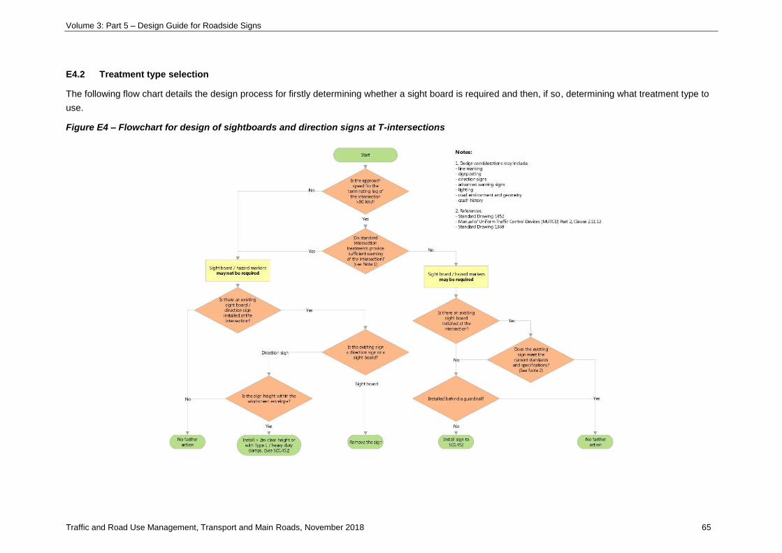
Volume 3: Part 5 – Design Guide for Roadside Signs
Traffic and Road Use Management, Transport and Main Roads, November 2018 65
E4.2 Treatment type selection
The following flow chart details the design process for firstly determining whether a sight board is required and then, if so, determining what treatment type to
use.
Figure E4 – Flowchart for design of sightboards and direction signs at T-intersections