Embed Size (px)
Citation preview

Tuesday, February 27, 2018 1
PART ONE: DC Circuits
Chapter 1. Basic concepts
THIS COURSE CAN BE FOUND AT:
http://users.utcluj.ro/~denisad

2/62
• An electrical circuit is an interconnection of electrical elements
A simple electrical circuit
Electric circuit of a radio transmitter
Electric circuits are used in numerous electrical systems to accomplish different tasks.
Our objectives in this course is not the study of various uses and applications of the circuits.
Rather, our major concern is the analysis of the circuits (study of the behavior of the
circuit):
- How does it respond to a given input
- How do the interconnected elements and devices in the circuit interact etc.
1.1 INTRODUCTION

3/62
1.2 SYSTEM OF UNITS
International System of Units (SI) adopted by the General Conference on Weights
and Measures in 1960

4/62
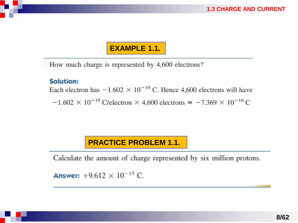
1.3 CHARGE AND CURRENT
• The most basic quantity in an electric circuit is the electric charge.
Charge is an electrical property of the atomic particles of which matter
consists, measured in coulombs (C)

5/62
1.3 CHARGE AND CURRENT
• The motion of charges creates electric current
- It is conventional to take the current flow as the
movement of positive charges. That is, opposite to the
flow of negative charges. (This convention was introduced by Benjamin Franklin (1706-1790), the
American scientist and inventor)
Electric current due to flow of
electronic charge in conductor - Because the current in metallic conductors is due to
negatively charged electrons, we will follow the
universally accepted convention that current is the net
flow of positive charges.
Electric current is the time rate of change of charge, measured in amperes (A)
The charge transferred between time t0 and t

6/62
1.3 CHARGE AND CURRENT
A direct current (DC) is
a current that remains
constant with time.
An alternating current (AC) is a
current that varies sinusoidally with
time.
- The direction of current flow is
conventionally taken as the direction of
positive charge movement.
a) Positive current flow b) negative current flow

7/62
1.3 CHARGE AND CURRENT
8/62
1.3 CHARGE AND CURRENT
PRACTICE PROBLEM 1.1.
EXAMPLE 1.1.

9/62
1.3 CHARGE AND CURRENT
EXAMPLE 1.2.
PRACTICE PROBLEM 1.2.

10/62
1.3 CHARGE AND CURRENT
EXAMPLE 1.3.
PRACTICE PROBLEM 1.3.

11/62
1.4 VOLTAGE
- To move the electron in a conductor in a particular
direction requires some work or energy transfer: an
external electromotive force (emf) also known as
voltage or potential difference.
Voltage (or potential difference) is the energy required to move a unit charge
through an element, measured in volts (V)
- w is energy in joules (J)
- Q is charge in coulombs (C)
Polarity of voltage vab

12/62
1.4 VOLTAGE
A DC voltage: voltage that remains constant with time (is represented by V).
Is commonly produced by a battery.
An AC voltage: voltage that varies sinusoidally with time (is represented by v).
Is commonly produced by an electric generator.

13/62
1.4 VOLTAGE

Current and voltage are the two basic variables in electric circuits.
The common trem signal is used for an electric quantity such as a current
or a voltage (or even electromagnetic wave) when it is used for conveying
information.
Engineers prefer to call such variables signals rather than mathematical
functions of time becuase of their importance in communications and other
disciplines.
14/62
1.4 VOLTAGE
Electric current is always through an element
and electric voltage is always across the
element between two points.
KEEP IN MIND:

15/62
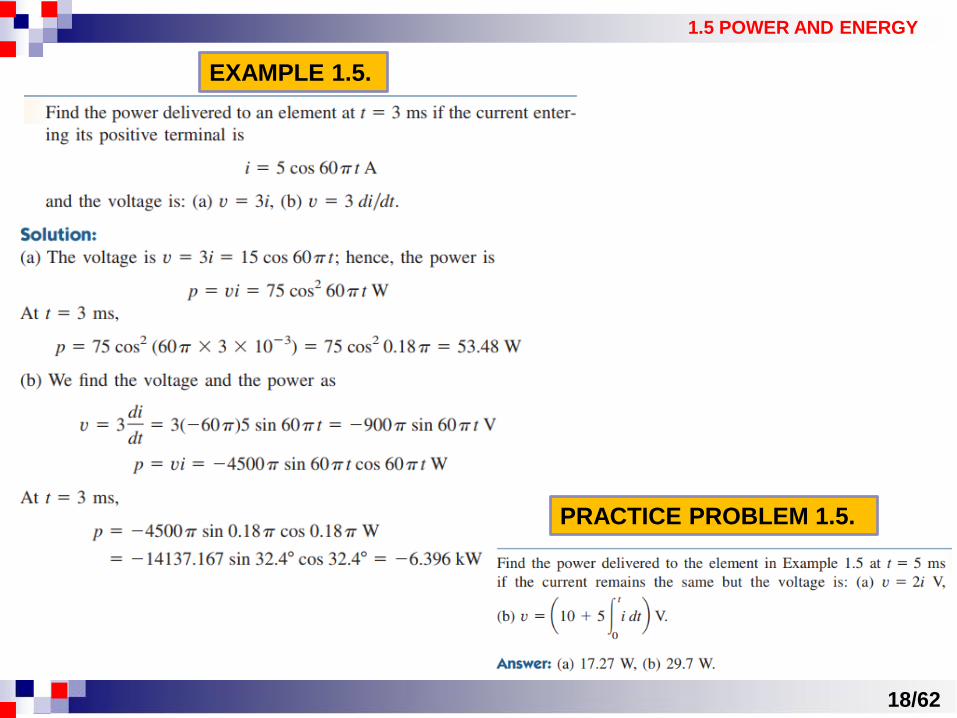
1.5 POWER AND ENERGY
Power is the time rate of expending or absorbing energy, measured in
watts (W)
or
- P is power in watts (W)
- w is energy in joules (J)
- t is time in seconds (s) - The power p is a time-varying quantity called the
instantaneous power.
- If p has a + sign, power is being delivered to or
absorbed by the element.
- If p has a - sign, power is being supplied by the
element.
Reference
polarities for
power using the
passive sign
convention

16/62
1.5 POWER AND ENERGY
Law of conservation of energy: the algebraic sum of
power in a circuit, at any instant of time, must be zero.
Energy is the capacity to do work, measured in joules (J).
The electric power utility companies measure
energy in watts-hours (Wh), where:

17/62
1.5 POWER AND ENERGY
EXAMPLE 1.4.
PRACTICE PROBLEM 1.4.
18/62
1.5 POWER AND ENERGY
EXAMPLE 1.5.
PRACTICE PROBLEM 1.5.

19/62
1.5 POWER AND ENERGY
EXAMPLE 1.6.
PRACTICE PROBLEM 1.6.

20/62
1.6 CIRCUIT ELEMENTS
There are two types of elements found in electric circuits:
PASSIVE ELEMENTS which are not capable to generate energy
(resistors, capacitors and inductors)
ACTIVE ELEMENTS which are capable to generate energy (generators,
batteries, operational amplifiers)
Source: [https://powerinception.com/]
Passive circuits and active circuits

An ideal independent source is an active element that provides a specified
voltage or current that is completely independent of other elements.
An ideal independent VOLTAGE source is an active element that delivers
to the circuit whatever current is necessary to maintain its terminal
voltage.
Element dipolar ideal, capabil să menţină între bornele sale o tensiune electrică independentă de
curentul debitat
Used for DC
voltage source
Used for time
varying voltage
source
Voltage - current characteristics 21/62
1.6 CIRCUIT ELEMENTS
Voltage – current characteristic

22/62
1.6 CIRCUIT ELEMENTS
An ideal independent CURRENT source is an active element that provides
a specified current completely independent of the voltage across the source.
Element dipolar ideal care debitează un curent de intensitate precizată independentă de tensiunea
între bornele sale.
- The ideal current source delivers to the circuit whatever voltage is necessary to
maintain the designated current.
Voltage – current characteristic
The arrows indicates the direction of current

23/62
1.6 CIRCUIT ELEMENTS
An ideal dependent (or controlled) source is an active element in which the
source quantity is controlled by another voltage or current.
- Dependent sources are useful in modeling
elements such us transistors, operational
amplifiers and integrated circuits.

25/62
REVIEW QUESTIONS

PART ONE: DC Circuits
Chapter 2. Basic Laws
THIS COURSE CAN BE FOUND AT:
http://users.utcluj.ro/~denisad

27/62
2.1 OHM’S LAW
- Materials in general have the characteristic behavior of resisting the flow of electric
charge. This physical property, or ability to resist current is kown as resistance (R).
- ρ is known as resistivity of the material (ohm/m)
- A cross section area of the material (m·m)
- L is the lenght of the material (m)
The resistance R of an element
denotes its ability to resist the
flow of electric current; it is
measured in ohms (Ω).

28/62
2.1 OHM’S LAW

29/62
Ohm’s Law states that the voltage V across a resistor is directly
proportional to the current I flowing through the resistor.
2.1 OHM’S LAW
- Since the value of R can range from zero to infinity, it is important that we consider
the two extreme possible values of R.
A short circuit is a circuit element with
resistance approaching to zero.
An open circuit is a circuit element
with resistance approaching infinity.

30/62
2.1 OHM’S LAW
- A resistors that obeys Ohm’s Law is kown as a linear resistor.
The current – voltage
characteristic of a linear resistor
The current – voltage characteristic
of a nonlinear resistor
- A resistors that not obeys Ohm’s Law is kown as a nonlinear resistor (its
resistance varies with current).
Linear circuits and non-linear circuits

31/62
2.1 OHM’S LAW

32/62
2.1 OHM’S LAW
Conductance G is the ability to conduct the flow of electric current; it
is measured in siemens (S).
- The power disipated by a resistor can be expressed in terms of R:
- The power disipated by a resistor can be expressed in terms of G:

EXAMPLE 2.1.
PRACTICE PROBLEM 2.1.
33/62

EXAMPLE 2.2.
34/62

PRACTICE PROBLEM 2.2.
35/62

36/62
2.2 NODES, BRANCHES and LOOPS
A branch (b) is the connections between two nodes.
A node (n) is the point of connection between more than two branches.
A loop (l) is any closed path in a circuit.
b=4
l=3
n=2
37/62
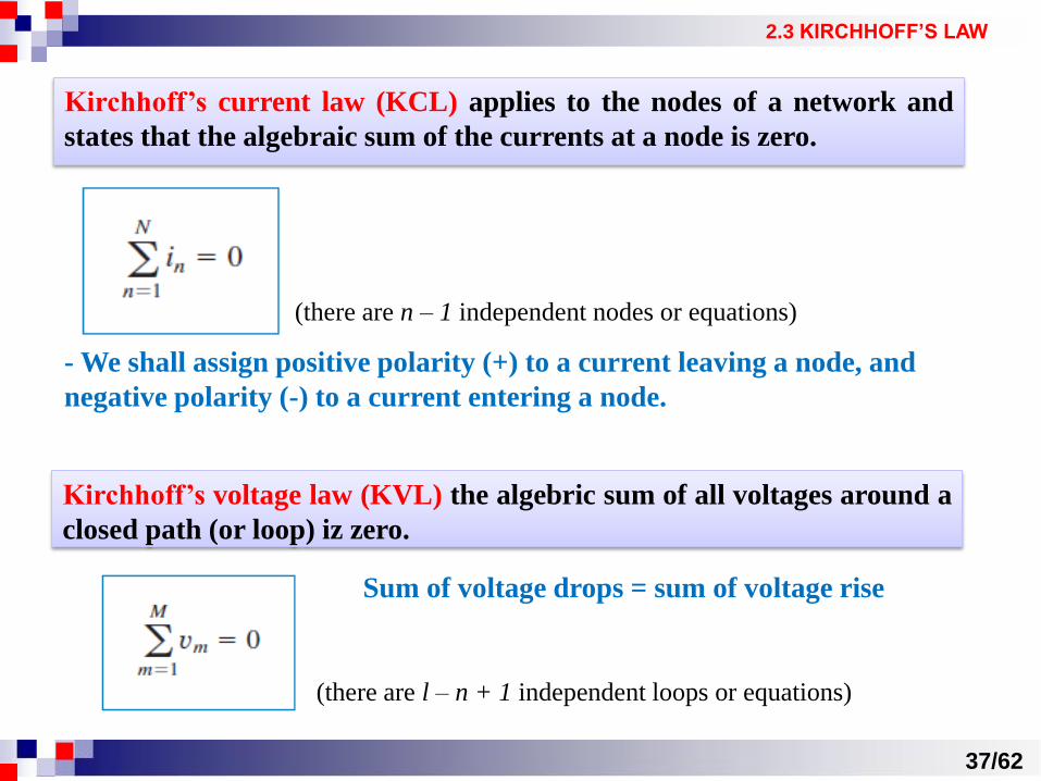
2.3 KIRCHHOFF’S LAW
(there are l – n + 1 independent loops or equations)
Kirchhoff’s current law (KCL) applies to the nodes of a network and
states that the algebraic sum of the currents at a node is zero.
(there are n – 1 independent nodes or equations)
- We shall assign positive polarity (+) to a current leaving a node, and
negative polarity (-) to a current entering a node.
Kirchhoff’s voltage law (KVL) the algebric sum of all voltages around a
closed path (or loop) iz zero.
Sum of voltage drops = sum of voltage rise

38/62
2.3 KIRCHHOFF’S LAW
For Examples and Practice problems
using Ohm’s Law, KCL and KVL, see SEMINAR 1

39/62
2.4 SERIES RESISTORS and VOLTAGE DIVISION
The equivalent resistance of any number of resistors connected in series
is the sum of the individual resistances.
Principle of voltage division
40/62
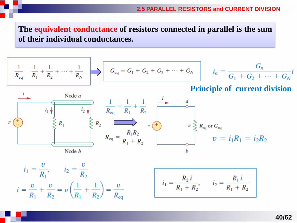
2.5 PARALLEL RESISTORS and CURRENT DIVISION
The equivalent conductance of resistors connected in parallel is the sum
of their individual conductances.
Principle of current division

41/62
2.6 WYE – DELTA TRANSFORMATIONS
- This situasions arise in circuits analysis when the resistors are neither in parallel nor in
series.
- Many circuits of the type shown in Fig.1 (a bridge network), can pe simplified by using
three-terminal equivalent networks such: the wye (Y) or tee (T) network, and delta (Δ) or pi
(Π) network.
Wye (Y) network Tee (T) network Delta (Δ) network Pi (Π) network
Fig.1 The bridge network
- They are used in three-phase networks,
electrical filters and matching networks

42/62
2.6 WYE – DELTA TRANSFORMATIONS
DELTA TO WYE CONVERSION
Wye (Y) network Delta (Δ) network
- We not need to memorize equations; to
transform Δ in Y, we create an extra node n and
follow this conversion rule:
Each resistor in the Y network is the
product of the resistors in the two
adiacent Δ branches, divided by the sum
of the three Δ resistors. Supeposition of Y and Δ
networks as an aid in
transforming one to another

43/62
2.6 WYE – DELTA TRANSFORMATIONS
43/62
2.6 WYE – DELTA TRANSFORMATIONS
WYE TO DELTA CONVERSION
- We not need to memorize equations; to transform Δ in Y, we create an extra node n and
follow this conversion rule:
Each resistor in the Δ network is the sum of the all possible products of Y
resistors taken two time, divided by the opposite Y resistor.

44/62
2.6 WYE – DELTA TRANSFORMATIONS
The Δ and Y networks are said to be balanced when:
Under this conditions, conversion formula become:
In making Δ/Y transformation, we do not take anything out of the circuit or
put anything new. We are merely substituting different but mathematically
equivalent three-terminal networks patterns to create a circuit in which
resistors are either in series or in parallel, allowing us to calculate Req if
necessary.
KEEP IN MIND:

45/62
For Examples and Practice problems
regarding calculation of Req, Geq and Δ/Y conversion,
see SEMINAR 1

50/62

51/62
REVIEW QUESTIONS

52/62
REVIEW QUESTIONS

53/62
References
[1] Charlews K. Alexander, Matthew N.O.Sadiku, Fundamentals of Electric
Circuits (Fifth Edition), published by McGraw-Hill, 2013
[2] Radu V. Ciupa, Vasile Topa, The Theory of Electric Circuits, published
by Casa Cartii de Stiinta, 1998
[3] Dan. D Micu, Laura Darabant, Denisa Stet et al., Teoria circuitelor
electrice. Probleme, published by UTPress, 2016