Embed Size (px)
Citation preview
PARTICLE IMPACT PREDICTION ON AN ARCHIMEDES SCREW
RUNNER BLADE FOR MICRO HYDRO TURBINE
NURUL SURAYA BINTI AZAHARI
Report submitted in partial fulfilment of the requirements
for the award of degree of
Bachelor of Mechanical Engineering
Faculty of Mechanical Engineering
UNIVERSITI MALAYSIA PAHANG
JUNE 2013
vii
ABSTRACT
Energy is one of the important sources in the world and important for developing
countries. In rural and remote areas, transmission and distribution of energy generated
from fossil fuels can be difficult and expensive and producing renewable energy such as
water turbine can locally offer a viable alternative. The subject study is conducted to
investigate the flow behaviour of water inside the turbine and predict the impact of
particle towards blade surface. For this reasons, computational fluid dynamics (CFD)
methods are used. The three-dimensional flow of fluid is numerically analysed using the
Navier-Stokes equation with standard k-ε turbulence model by applying some boundaries
condition such as steady state flow condition, isentropic flow and isothermal temperature.
The numerical results such as velocity streamlines, flow pattern and pressure contour for
flow of water entering the blade are compared with the experimental results which
obtained by other researches. This study shows that the prediction of particle impact
occurs mostly on the entering surface blade and along the leading edge of the screw
runner. Any modification on the design of the screw runner blade can be analyse for
further study.

viii
ABSTRAK
Tenaga merupakan salah satu sumber yang penting di seluruh dunia dan negara-negara
yang sedang membangun. Bagi kawasan luar bandar dan pedalaman, penghantaran dan
pembahagian tenaga yang dijana daripada bahan fosil adalah sukar dan penghasilan
tenaga yang boleh diperbaharui merupakan salah satu alternatif. Kajian yang dijalankan
adalah untuk mengkaji aliran air yang terbentuk di dalam turbin dan meramalkan kesan
zarah ke atas permukaan bilah. Pengiraan bendalir dinamik (CFD) merupakan salah satu
cara untuk mengkaji aliran air. Aliran cecair tiga dimensi (3D) dianalisis menggunakan
persamaan Navier-Stokes dengan menggunakan model k-ε dan mengaplikasi keadaan
aliran yang stabil, aplikasi aliran isentropi dan bersuhu malar. Halaju arus, corak aliran
dan kontur tekanan untuk aliran air yang memasuki bilah dibandingkan dengan keputusan
eksperimen yang dilakukan oleh pengkaji yang terdahulu. Keputusan kajian
menunjukkan bahawa kesan zarah kebanyakannya berlaku pada permukaan bilah yang
pertama dan sepanjang pinggir utama bilah turbin. Pengubahsuaian pada rekabentuk bilah
boleh dianalisa untuk kajian di masa akan datang.

ix
TABLE OF CONTENTS
Page
TITLE i
EXAMINER DECLERATION ii
SUPERVISOR’S DECLARATION iii
STUDENT’S DECLARATION iv
DEDICATION v
ACKNOWLEDGEMENTS vi
ABSTRACT vii
ABSTRAK viii
TABLE OF CONTENTS ix
LIST OF TABLES xii
LIST OF FIGURES xiii
LIST OF SYMBOLS xv
LIST OF ABBREVIATIONS xvi
LIST OF APPENDICES xvii
CHAPTER 1 INTRODUCTION
1.1 Project Background 1
1.2 Problem Statement 2
1.3 Objectives 2
1.4 Scopes of the Project 3
x
CHAPTER 2 LITERATURE REVIEW
2.1 Micro Hydro Turbine 4
2.2 Design of the Archimedes Screw Blade 4
2.3 Governing Equations 6
2.4 Turbulence Flow Modelling 8
2.5 CFD Simulation 9
2.6 Turbine Blade Surface Erosion 11
CHAPTER 3 METHODOLOGY
3.1 Flow Chart 16
3.2 Design Concept 18
3.2.1 Concept of Archimedes Screw 18
3.3 Design Phase using Solid works 20
3.4 Simulation Phase using ANSYS-CFX 23
3.4.1 Setup 23
3.4.2 Boundary Conditions 24
3.4.3 Velocity Components 24
3.4.4 Turbulence Characteristics 24
3.4.5 Computational Fluid Dynamics Simulation 25
3.5 Validation of flow along the Z axis of the flow path 29
CHAPTER 4 RESULTS AND DISCUSSION
4.1 Introduction 30
4.2 Qualitative Analysis of Particle Flow Prediction 31
4.2.1 Simulation Process 31
4.2.2 Velocity Streamlines 32
4.2.3 Flow Patterns 35
4.2.4 Pressure Contour 37

xi
CHAPTER 5 CONCLUSION AND RECOMMENDATIONS
5.1 Introduction 41
5.2 Conclusion 41
5.3 Recommendation 42
REFERENCES 43
APPENDICES 45

xii
LIST OF TABLES
Table No. Title Page
Table 3.1 The diameter and dimension used 22
Table 3.2 Parameter Design 28
xiii
LIST OF FIGURES
Figure No. Title Page
2.1 The profile view of two-bladed Archimedes Screw 5
2.2 Side elevation of the Archimedes screw 6
2.3 The dimensionless radial-axial vector plots 10
2.4 The separation of flow in Pelton bucket 11
2.5 Volcanic ash deposition on turbine vanes 13
2.6 Erosion rate variation with impact angle 14
2.7 The streamlines and pressure contour of the fan blade 15
3.1 Flow Chart 17
3.2(a) Side view of Archimedean screw 19
3.2(b) Plan view of submerged blade 20
3.3 Design of the screw runner blade with the flow path 22
3.4 Blade design with flow in Solidworks 19
3.5 Schematic diagram of CFD code 23
3.6 Three-dimensional solid model of the helical blade 25
3.7 Method of meshing 26
3.8(a) Zoom at the inlet velocity of the flow 27
3.8(b) Zoom at wall of the water flow 27
3.9 Velocity profile of Pahang River 29
4.1 Vessel configuration with screw runner blade 32
4.2 Velocity streamline of water entering the blade 33
4.3 Velocity streamline at the inlet flow 34
4.4 Velocity streamline at the outlet flow 35
4.5 Velocity vector of the overall water flow 36
4.6 Velocity vector of the water at inlet flow 37
4.7 Pressure contour of the turbine blade 38
xiv
4.8 Front view pressure contour around the screw blade 39
4.9 Back view pressure contour around the screw blade 40
CHAPTER 1
INTRODUCTION
1.1 PROJECT BACKGROUND
The Archimedes screw are created over 2000 years ago and used to raise the
water. As the time goes by, it has been tested and modified for the other uses such as a
blade to generate electricity as the diminishing of the energy resources. Historically, this
screw was used in irrigation and drainage to lift the water to a higher level were
generally powered by human or beast and only in small versions. On the other hand,
when used as a hydro turbine, the principle of the Archimedes screw pump is still same,
but acts in reverse. The screw pump function from the bottom of the channel and the
blade will rotate while at the same time, flow the water through the screw blade and
transfer the water to the upper channel.
On the other hand, for micro hydro turbine, the water will enter the screw at the
top and the weight of the water will pushes on the helical blade and make the screw to
rotate. The rotation can be used to produce the electricity. Basically, these screw runner
turbine can work efficiently at head not less than 1 meter and not more than 5 meter, but
practically people always used 3 meter maximum diameter. Besides, there are another
impact that will cause the blade does not function maximally such as particle impact,
acoustic impact, premature failure and etc. Based on (Brada, 1999) , the weight of the
water that cover by the channel will make the screw blade rotate.
2
The usual problem in the screw runner blade for micro hydro turbine is the
failure to achieve maximum performance of blade due to the particle impact. Particle
impact may reduce the negative pressure spike and reduce energy extraction efficiency,
which can affect the pressure on the blade surfaces. The review of this research, for
example, was given by (Liu, 2010) mentioned in, the analysis between the screw
propellers and horizontal axis turbines in terms of geometry and motion parameters,
such as thrust coefficients, shaft/torque coefficients, blade surface distributions and
downstream velocity profiles .CFD results verify the connection between the pressure
fluctuations and more complex pattern has emerged comprising of the near wall fluid
correlated with the actual inflow (Sheard, 2012). Besides, the computational methods is
one of the best way to predict the particle trajectories, the areas that the erosion always
occurred.
1.2 PROBLEM STATEMENT
Nowadays, the lacking of fuels and climate change issue become serious and
one of the best solution to avoid from energy diminished is by using a renewable energy.
The renewable energy is comes from natural resources such as sunlight, wind, rain, tides
and geothermal heat. A development of strong renewable energy sector would ensure
that the future energy security of the country and effects of climate change due the
greenhouse gases emission. One of the renewable energy which is micro hydro turbine
is always being used to generate energy, but there are such problems that affect the
turbine performance, which is due to erosion. There are certain surfaces in the blade that
always cause erosion due to particle impact during the inflow of river.
1.3 OBJECTIVES
The objectives of this study are as follow:-
1. To study the flow behaviour of water inside the turbine.
2. To predict the impact of particle towards the surfaces of the blade.

3
1.4 SCOPES OF THE PROJECT
The project scopes of this study to achieve the objectives are as listed below:-
1. Sketching two concept design of the screw runner blade of micro hydro
turbine.
2. Choose the best design and draw the screw runner blade by using CAD
software (Solid works).
3. The dimension of the screw runner blade are based on the previous research
journal (Muller, 2009).
4. The length of the blade, L=5600mm, the screw angle,α= 23.580, the blade
diameter d=1040mm,hub diameter Dh=390mm, casing blade diameter D=
1200mm, the head difference H=2240mm, pitch blade P=380mm and helix
turns m=14.
5. The CFD-Ansys CFX software will be used to know the analysis result by
applying the initial condition which is steady state condition (VAin=VAout)
and water velocity of 2.47 m/s.
6. The vector velocity, the velocity streamline and pressure contour is found by
set-up all the things in the Ansys software. The blade is assumed as
stationary due to the complexity of the software set-up.
4
CHAPTER 2
LITERATURE REVIEW
2.1 MICRO HYDRO TURBINE
Micro hydro turbines is one of popular renewable energy that have been used
nowadays. It may produce about 100 kW power and basically used by home owner or
small business owner. The turbine extract energy from the fluid and change it into an
energy such as mechanical energy output and usually in rotating form or shaft. The fluid
from the outflow usually have energy loss, normally in pressure loss. In general, most
turbine have a same problems which is noise, vibration, cavitation, cracking, the reducing
of efficiency or performance and at the same time make the blade of the turbine damage.
Other than that, the impact on the blade during the turbine’s operation can cause the
maintenance costs increase.
2.2 DESIGN OF THE ARCHIMEDES SCREW BLADE
Design is one of the important factor in creating a product because from the
design, there are a lot of effect especially in the form of efficiency of the product. For
example, the design of the screw blade is depends on several factor such as internal
parameters and external parameters (Rorres, 2000). The example of internal parameters
5
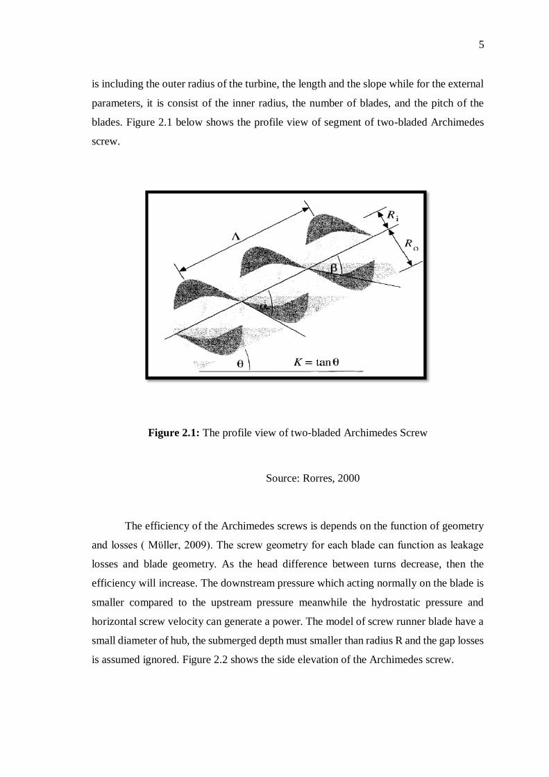
is including the outer radius of the turbine, the length and the slope while for the external
parameters, it is consist of the inner radius, the number of blades, and the pitch of the
blades. Figure 2.1 below shows the profile view of segment of two-bladed Archimedes
screw.
Figure 2.1: The profile view of two-bladed Archimedes Screw
Source: Rorres, 2000
The efficiency of the Archimedes screws is depends on the function of geometry
and losses ( Mϋller, 2009). The screw geometry for each blade can function as leakage
losses and blade geometry. As the head difference between turns decrease, then the
efficiency will increase. The downstream pressure which acting normally on the blade is
smaller compared to the upstream pressure meanwhile the hydrostatic pressure and
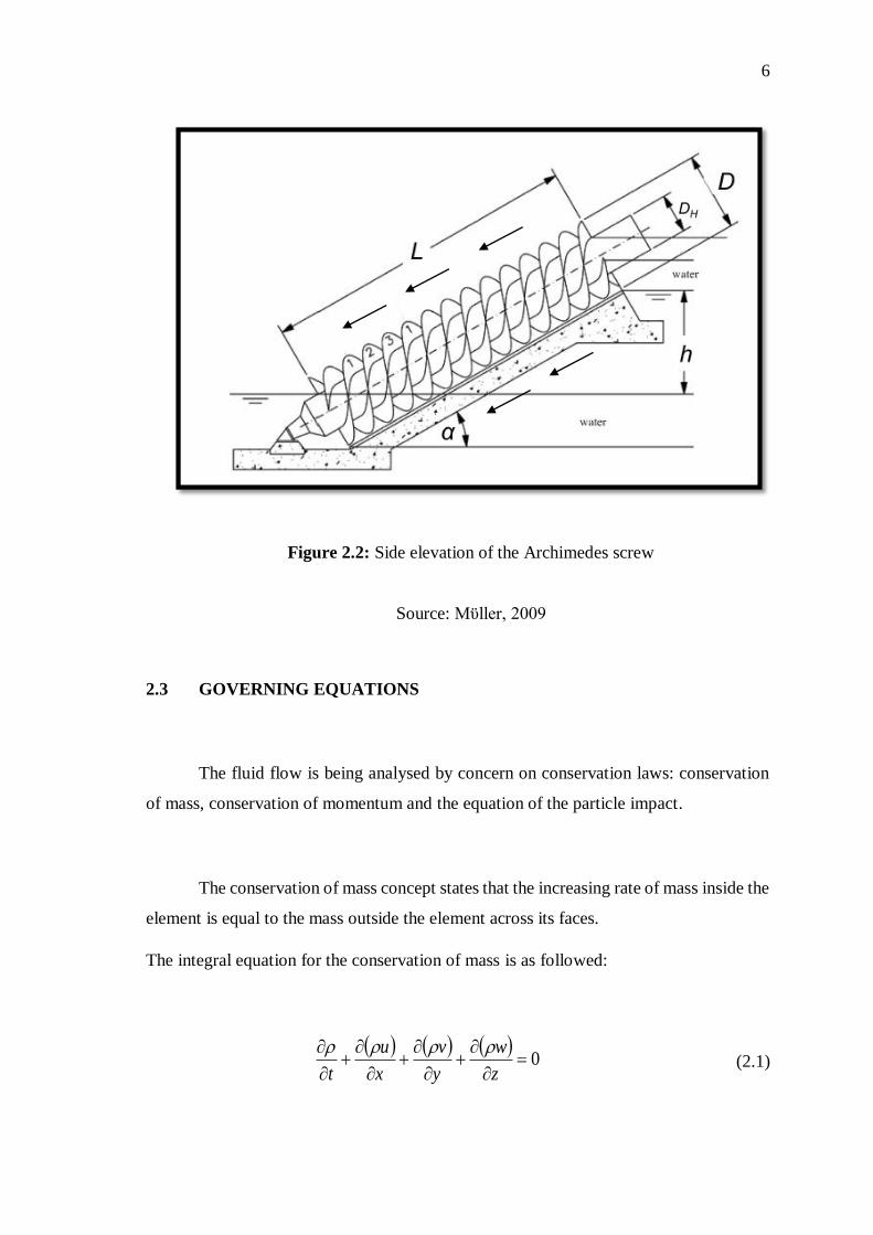
horizontal screw velocity can generate a power. The model of screw runner blade have a
small diameter of hub, the submerged depth must smaller than radius R and the gap losses
is assumed ignored. Figure 2.2 shows the side elevation of the Archimedes screw.
6
Figure 2.2: Side elevation of the Archimedes screw
Source: Mϋller, 2009
2.3 GOVERNING EQUATIONS
The fluid flow is being analysed by concern on conservation laws: conservation
of mass, conservation of momentum and the equation of the particle impact.
The conservation of mass concept states that the increasing rate of mass inside the
element is equal to the mass outside the element across its faces.
The integral equation for the conservation of mass is as followed:
0
z
w
y
v
x
u
t
(2.1)

7
The conservation of momentum is based on the Newton’s second law, which
states that the fluid particle acceleration is related to the sum forces acting on the fluid
particle. The flow field is defined in three components (u,v and w) or in generally x,y and
z components.
The integral equation of momentum conservation for x,y and z direction are shown as in
Eq. (2.2), Eq. (2.3) and Eq. (2.4) respectively :
Momentum for x-direction:
bodyforce
x
zxyxxx FzyxDt
Du (2.2)
Momentum for y-direction:
bodyforce
y
zyyyxyF
zyxDt
Du (2.3)
Momentum for z-direction:
bodyforce
zzzyxxz FzyxDt
Du (2.4)
The normal stresses xx , yy and zz were due to the combination of pressure and
normal viscous stress components xx , yy and zz acting perpendicular to the control
volume.
8
The particle move through the blade and follow the flow of the water. The forces
that acting on the wall due to particles, have difference and own velocity. The particle
usually have a sphere shape and mostly, the particle-particle interactions are ignored
cause by low particle concentrations experienced.
The equation of motion is expressed in Eq. (2.5):
F AMF GF LF Ddt
v pdV pp (2.5)
Based on Eq. (2.5) where FD is the drag force, FL is the lift force, FG is gravity force
and FAM is added mass due to acceleration of neighbouring fluid.
2.4 TURBULENCE FLOW MODELLING
Turbulence flow is a most of a fluid flow that always occurred around us. For
example, the flow around the bodies of the cars, aeroplanes and buildings are turbulent.
The flow is considered turbulent when consists of irregular, diffusivity, large Reynolds
Numbers and dissipative. There are several famous turbulence models that are always
used by the previous researcher such as two-equation k-ω model of Wilcox, the two-
equation of k-ε model of Launder and Sharma, the two-equation k-ω/k-ε SST model of
Menter and one-equation model of Spalart and Allmaras ( Bardina, 1997 ).
The choice of numerical methods are important to predict the turbulent kinetic
energy. The k-ε and RNG models is used due to convergence difficulties related to
Reynolds stress model and have a little effect on the mean flow and turbulent kinetic
energy ( Aubin, 2004 ). Every turbulence model have own specialities based on the
complexity. Previous researcher ( Gartmann, 2011 ) states that the characteristics of the

9
channel flow properties is observed in portable wind tunnel with rainfall simulation by
using Reynolds-averaged Navier-Stokes (RANS) k-ε turbulence model.
The standard k-ε turbulence model equation are expressed as in Eq (2.4) and (2.5) below:
2)(
2)(
dy
vRdlm
c
vok
(2.4)
3)(
4)(
dy
v Rdl m
c
vo
(2.5)
Based on Eq. (2.4) and Eq. (2.5) above where VR is the velocity of neighbour to
wall and y is the distance of the adjacent node to the solid wall.
2.5 CFD SIMULATION
Computational Fluid Dynamics is a solver that is used to illustrate the
computational study. From the simulation, several factor can be determined and can be
compared with the experiment data. The advantages of using the simulation is the
researcher can study more on complex problem that is impossible to be done
experimentally and other than that, the cost to do the product is also decrease as the
researcher just need to set-up the simulation. The limitation of the CFD software is this
simulation cannot be used to confirm the accuracy of the simulation is succeed. The
results from simulation need to be validate with the suitable and relevant experimental
data.
The simulation of the three dimensional distribution of solid particle in turbulent
liquid flow with k-ε turbulence model have been used by (Micale, 2000) to study a simple

10
settling velocity model and assume the particles are transported as a passive scalar. The
increase in particle drag coefficient due to turbulent flow must be accounted to give a
good agreement between simulation and experimental data.
The modelling approach, turbulence model and numerical scheme is the factor
that influence the modelling turbulent flow in stirred tank (Aubin, 2004). The vector plot
have been used to present the results as shown in Figure 2.3. The CFD modelling
approaches predict the flow patterns which have good agreement, quantitatively and
qualitatively with the experimental data.
Figure 2.3: The dimensionless radial-axial vector plots
Source: Aubin, 2004

11
2.6 TURBINE BLADE SURFACE EROSION
The normal particle acceleration will separate the particle from the
direction of the flow. Most of the accelerating particle will strikes the first surface of the
turbine. The size of particle may affect the surface of the blade. As stated by (Thapa,
2004), the erosion will occurred most on the needle if the particle are fine, more erosion
in bucket if the particle is course and for the medium particle, then both bucket and needle
are equally have eroded area. Figure 2.4 indicates the separation of particle in a Pelton
bucket. The red-dot line is shows the affect due to the larger moving particle, while the
black-dot line indicate the smaller particle impact to the blade. The blue line illustrate the
original of water surface.
Figure 2.4: The separation of flow in Pelton bucket
Source: Thapa, 2004
12
The dynamic action of sediment of flowing water can cause the sediment erosion
to the turbine. The particle dynamics simulation indicates that many particles hit the vane
pressure surface which the larger particles across over and impact the vane suction surface
towards trailing edge ( Tabakoff, 2005). Besides, the trajectories shows that the impact
of particle always occurred at the pressure surface and part of the suction surfaces.
Besides, the blade surface that was hit by some particles will diverge from flow due to
high inertia.
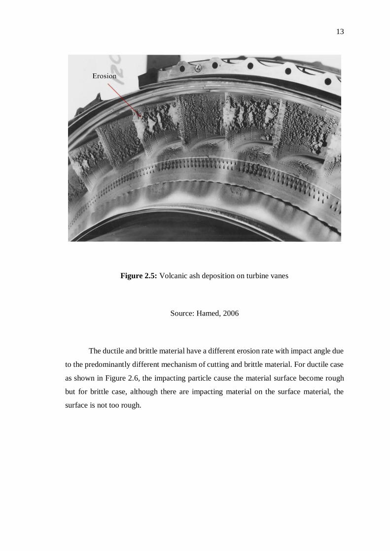
The parameter effect the losses of surface material as consequences of erosion (
Hamed, 2006). For example, at the engine inlet engine, the aircrafts standing or moving
can blow sand, ash, dust and other particles that enter into the engine and erosion can
occurred. Test that have been done at University of Cincinnati showed that the quartz
sand is less erosive than volcanic ash. Figure 2.5 below shows the volcanic ash deposition
on turbine vanes.
13
Figure 2.5: Volcanic ash deposition on turbine vanes
Source: Hamed, 2006
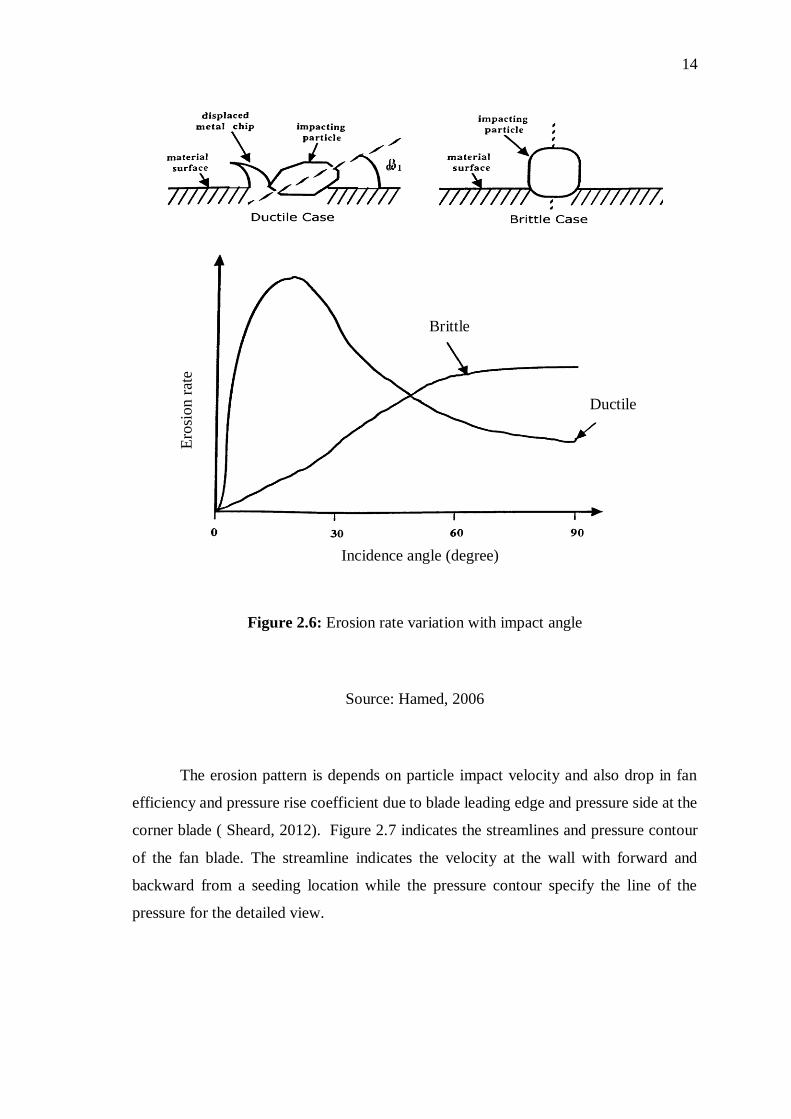
The ductile and brittle material have a different erosion rate with impact angle due
to the predominantly different mechanism of cutting and brittle material. For ductile case
as shown in Figure 2.6, the impacting particle cause the material surface become rough
but for brittle case, although there are impacting material on the surface material, the
surface is not too rough.
14
Figure 2.6: Erosion rate variation with impact angle
Source: Hamed, 2006
The erosion pattern is depends on particle impact velocity and also drop in fan
efficiency and pressure rise coefficient due to blade leading edge and pressure side at the
corner blade ( Sheard, 2012). Figure 2.7 indicates the streamlines and pressure contour
of the fan blade. The streamline indicates the velocity at the wall with forward and
backward from a seeding location while the pressure contour specify the line of the
pressure for the detailed view.
Brittle
Ductile
Ero
sion r
ate
Incidence angle (degree)

15
Figure 2.7: The streamlines and pressure contour of the fan blade
Source: Sheard, 2012
Particle transport through the rotor also influenced the streamlines and pressure
contour of the blade. The complex pattern is seen near the wall fluid caused by the actual
inflows incidence angle. Both figure above shows the existing of leading edges separation
that radially outward. The blunting of the leading edge thickness on the pressure and
suction sides results an erosion and the pressure side surface is larger than the suction
side.


![Archimedes Powerpoint 8.12.2008.ppt [Kompatibilitätsmodus]haftendorn.uni-lueneburg.de/geschichte/griechen/Archimedes-berlips-nolte.pdf · Biographie IBiographie I • Archimedes](https://img.pdfslide.net/doc/110x75/5d66c48288c99356168b52cb/archimedes-powerpoint-8122008ppt-kompatibilitaetsmodus-biographie-ibiographie.jpg)