Embed Size (px)
Citation preview
8/13/2019 PAS3 Technical Datasheet
http://slidepdf.com/reader/full/pas3-technical-datasheet 1/4
DATA SHEET
Date Apr. 10, 2002
EDS11-141a
FEATURES
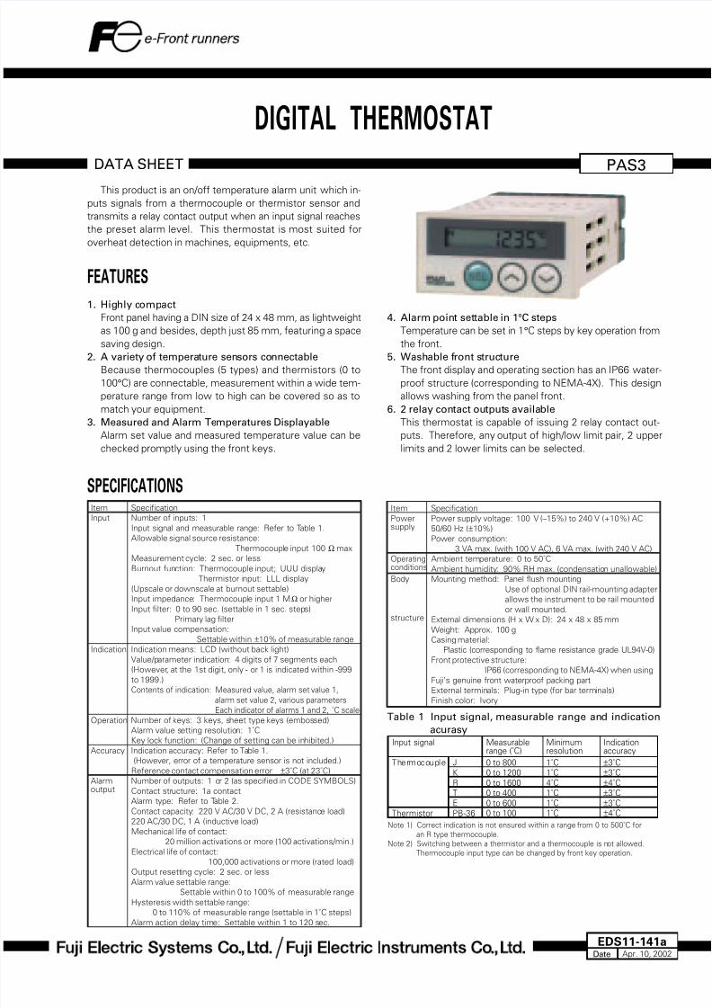
1. Highly compact
Front panel having a DIN size of 24 x 48 mm, as lightweight
as 100 g and besides, depth just 85 mm, featuring a space
saving design.
2. A variety of temperature sensors connectableBecause thermocouples (5 types) and thermistors (0 to
100°C) are connectable, measurement within a wide tem-
perature range from low to high can be covered so as to
match your equipment.
3. Measured and Alarm Temperatures Displayable
Alarm set value and measured temperature value can be
checked promptly using the front keys.
SPECIFICATIONS
Item Specification
Input Number of inputs: 1
Input signal and measurable range: Refer to Table 1.Allowable signal source resistance:
Thermocouple input 100 Ω max.
Measurement cycle: 2 sec. or less
Burnout function: Thermocouple input; UUU display
Thermistor input: LLL display
(Upscale or downscale at burnout settable)
Input impedance: Thermocouple input 1 MΩ or higher
Input filter: 0 to 90 sec. (settable in 1 sec. steps)
Primary lag filter
Input value compensation:
Settable within ±10% of measurable range
Indication Indication means: LCD (without back light)
Value/parameter indication: 4 digits of 7 segments each
(However, at the 1st digit, only - or 1 is indicated within -999
to 1999.)
Contents of indication: Measured value, alarm set value 1,
alarm set value 2, various parameters
Each indicator of alarms 1 and 2, ˚C scale Operation Number of keys: 3 keys, sheet type keys (embossed)
Alarm value setting resolution: 1˚C
Key lock function: (Change of setting can be inhibited.)
Accuracy Indication accuracy: Refer to Table 1.
(However, error of a temperature sensor is not included.)
Reference contact compensation error: ±3˚C (at 23˚C)
Alarm Number of outputs: 1 or 2 (as specified in CODE SYMBOLS)output Contact structure: 1a contact
Alarm type: Refer to Table 2.
Contact capacity: 220 V AC/30 V DC, 2 A (resistance load)
220 AC/30 DC, 1 A (inductive load)
Mechanical life of contact:
20 million activations or more (100 activations/min.)
Electrical life of contact:
100,000 activations or more (rated load)
Output resetting cycle: 2 sec. or less
Alarm value settable range:Settable within 0 to 100% of measurable range
Hysteresis width settable range:
0 to 110% of measurable range (settable in 1˚C steps)
Alarm action delay time: Settable within 1 to 120 sec.
PAS3
This product is an on/off temperature alarm unit which in-
puts signals from a thermocouple or thermistor sensor and
transmits a relay contact output when an input signal reaches
the preset alarm level. This thermostat is most suited for
overheat detection in machines, equipments, etc.
DIGITAL THERMOSTAT
4. Alarm point settable in 1°C steps
Temperature can be set in 1°C steps by key operation from
the front.
5. Washable front structureThe front display and operating section has an IP66 water-
proof structure (corresponding to NEMA-4X). This design
allows washing from the panel front.
6. 2 relay contact outputs available
This thermostat is capable of issuing 2 relay contact out-
puts. Therefore, any output of high/low limit pair, 2 upper
limits and 2 lower limits can be selected.
Item Specification
Power Power supply voltage: 100 V (–15%) to 240 V (+10%) AC
supply 50/60 Hz (±10%)Power consumption:
3 VA max. (with 100 V AC), 6 VA max. (with 240 V AC)
Operating Ambient temperature: 0 to 50˚Cconditions Ambient humidity: 90% RH max. (condensation unallowable)
Body Mounting method: Panel flush mounting
Use of optional DIN rail-mounting adapter
allows the instrument to be rail mounted
or wall mounted.structure External dimensions (H x W x D): 24 x 48 x 85 mm
Weight: Approx. 100 g
Casing material:
Plastic (corresponding to flame resistance grade UL94V-0)
Front protective structure:
IP66 (corresponding to NEMA-4X) when using
Fuji’s genuine front waterproof packing part
External terminals: Plug-in type (for bar terminals)
Finish color: Ivory
Table 1 Input signal, measurable range and indication
acurasyInput signal
Thermocouple J
K
R
T
E
Thermistor PB-36
Measurablerange (˚C)
0 to 8000 to 1200
0 to 16000 to 400
0 to 6000 to 100
Minimumresolution
1˚C1˚C
4˚C1˚C
1˚C1˚C
Indicationaccuracy
±3˚C±3˚C
±4˚C±3˚C
±3˚C±4˚C
Note 1) Correct indication is not ensured within a range from 0 to 500˚C for
an R type thermocouple.
Note 2) Switching between a thermistor and a thermocouple is not allowed.
Thermocouple input type can be changed by front key operation.
8/13/2019 PAS3 Technical Datasheet
http://slidepdf.com/reader/full/pas3-technical-datasheet 2/4
PAS3
CODE SYMBOLSTable 2 Alarm types
Set valuenotation
Action diagram(Note 1)
Code ofPA1, 2
0
1
2
3
4
5
6
7
8
–
No
No
Yes
Yes
No
No
Yes
Yes
Noalarm
Upperlimit
Lower
limit
Upper limit
Lowerlimit
Upperlimit
Lowerlimit
Upperlimit
Lowerlimit
–
Absolutevalue
Absolute
value
Absolutevalue
Absolutevalue
Absolutevalue
Absolutevalue
Absolutevalue
Absolutevalue
–
Relayexcitation
Relay
excitation
Relayexcitation
Relayexcitation
Relay non-excitation
Relay non-excitation
Relay non-excitation
Relay non-excitation
Withholding
(Note 2)
Relayaction
at alarm
Alarmdirection
(Note 1) How to read action
area: A range in which “ALM1 or ALM2” is indicated on LCD at the front.
area: A range in which alarm relay is excited
point: Alarm set value
The horizontal axis represents measured values (PV).
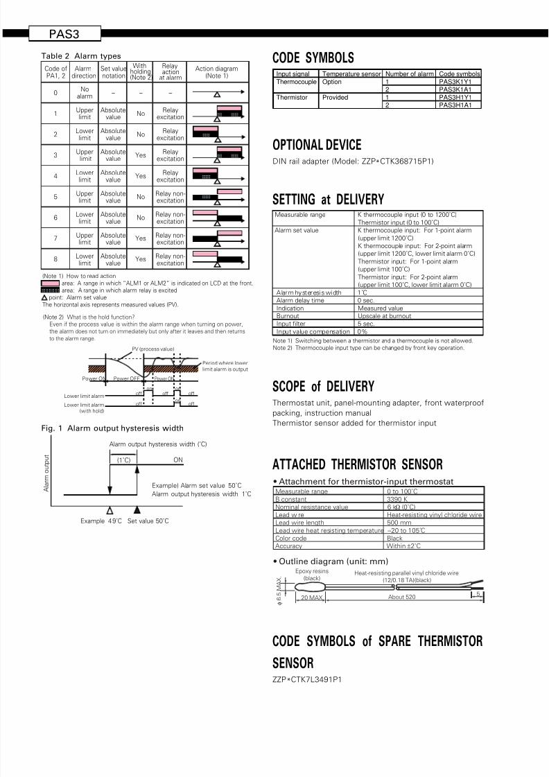
(Note 2) What is the hold function?
Even if the process value is within the alarm range when turning on power,
the alarm does not turn on immediately but only after it leaves and then returns
to the alarm range.
Lower limit alarm (with hold)
Power OFFPower ON Power ON
off
offon on
onoff
offoff
PV (process value)
Period where lowerlimit alarm is output
Lower limit alarm
Fig. 1 Alarm output hysteresis width
Example 49˚C Set value 50˚C
Alarm output hysteresis width (˚C)
Example) Alarm set value 50˚C
Alarm output hysteresis width 1˚C
ON(1˚C)
A l a r m o
u t p u t
Input signal
Thermocouple
Thermistor
Number of alarm
12
12
Code symbols
PAS3K1Y1PAS3K1A1
PAS3H1Y1PAS3H1A1
Temperature sensor
Option
Provided
SETTING at DELIVERYMeasurable range K thermocouple input (0 to 1200˚C)
Thermistor input (0 to 100˚C)
Alarm set value K thermocouple input: For 1-point alarm
(upper limit 1200˚C)
K thermocouple input: For 2-point alarm
(upper limit 1200˚C, lower limit alarm 0˚C)
Thermistor input: For 1-point alarm
(upper limit 100˚C)Thermistor input: For 2-point alarm
(upper limit 100˚C, lower limit alarm 0˚C)
Alarm hysteresis width 1˚C
Alarm delay time 0 sec.
Indication Measured value
Burnout Upscale at burnout
Input filter 5 sec.
Input value compensation 0%
Note 1) Switching between a thermistor and a thermocouple is not allowed.
Note 2) Thermocouple input type can be changed by front key operation.
SCOPE of DELIVERY
Thermostat unit, panel-mounting adapter, front waterproof
packing, instruction manual
Thermistor sensor added for thermistor input
ATTACHED THERMISTOR SENSOR
• Attachment for thermistor-input thermostat
• Outline diagram (unit: mm)
Measurable range 0 to 100˚C
B constant 3390 K
Nominal resistance value 6 kΩ (0˚C)
Lead wire Heat-resisting vinyl chloride wire
Lead wire length 500 mm
Lead wire heat resisting temperature –20 to 105˚C
Color code Black
Accuracy Within ±2˚C
About 5205
Epoxy resins
(black)Heat-resisting parallel vinyl chloride wire
(12/0.18 TA)(black)
φ
6 . 5
M A X .
20 MAX.
CODE SYMBOLS of SPARE THERMISTOR
SENSOR
ZZP*CTK7L3491P1
OPTIONAL DEVICE
DIN rail adapter (Model: ZZP*CTK368715P1)

8/13/2019 PAS3 Technical Datasheet
http://slidepdf.com/reader/full/pas3-technical-datasheet 3/4
OUTLINE DIAGRAM (Unit:mm)
DIN RAIL ADAPTER
2 4
Waterproof packing
Mounting adapter
Panel (1 ≤ t ≤ 8)
48
8584
3 4 . 2
1
4
P V S ET 1 S ET 2
ALM1ALM2
2 2
PANEL CUTOUT DIAGRAM (Unit:mm)
For close mounting in horizontal directionFor mounting “n” units
2 2 . 2
45.0+0.5
0
57 MIN.
5 0 M I N .
+ 0 . 3 0
(48 X n–3)+0.5 0
2 2 . 2
+ 0 . 3
0
This mounting does not meet NEMA-4X/IP66(front waterproof specification).(Because the packing cannot be used in horizontallyclose mounting.)
DIN rail
DIN rail adapter (option)
For wall mounting
MAX. torque 0.49Nm
PAS3...MFD.
No.
52.4
PV SET1 SET2
ALM1 ALM2
4
5 .
4
9 6 .
2
9 2 .
5
9
43.8
3 6 . 8
M 4
2 - ø 4 . 3

8/13/2019 PAS3 Technical Datasheet
http://slidepdf.com/reader/full/pas3-technical-datasheet 4/4
PAS3
CONNECTION DIAGRAM
1 2 3
2 3
4 5 6 7 8 9
Thermocoupleinput
Alarm output 1
Thermistor
Alarm output 2 Power supplyAC 100-240 V
50/60 Hz
– +
USABLE WIRING MATERIALS• Wire
Gauge: AWG28 (0.1 mm2) ... AWG16 (1.25 mm
2)
Strip-off length: 5 to 6 mm
• Bar terminal
Dimension of strip-off conductor section: 2 x 1.5 mm or smallerLength of strip-off conductor section: 5 to 6 mm
AWG28...AWG16
5 to 6 mm
5 to 6 mm2MAX.
1.5MAX.
CONNECTION METHOD
PAS3
Screw driver
Wires
Information in this catalog is subject to change without notice. Printed in Japan
Head office6-17, Sanbancho, Chiyoda-ku, Tokyo 102-0075, Japan
http://www.fesys.co.jp
Sales Div.International Sales Dept.No.1, Fuji-machi, Hino-city, Tokyo, 191-8502 Japan
Phone: 81-42-585-6201, 6202
Fax: 81-42-585-6187
http: //www.fic-net.co.jp
Caution on Safety
*Before using this product, be sure to read its instruction manual in advance.