Embed Size (px)
Citation preview
FOR:
PASSENGER CAR/LIGHT TRUCK WHEELS
OPERATION INSTRUCTIONS
Form ZEEWB502A 5819-5
VP
I SY
ST
EM
III
CO
MP
UT
ER
WH
EE
L B
AL
AN
CE
R


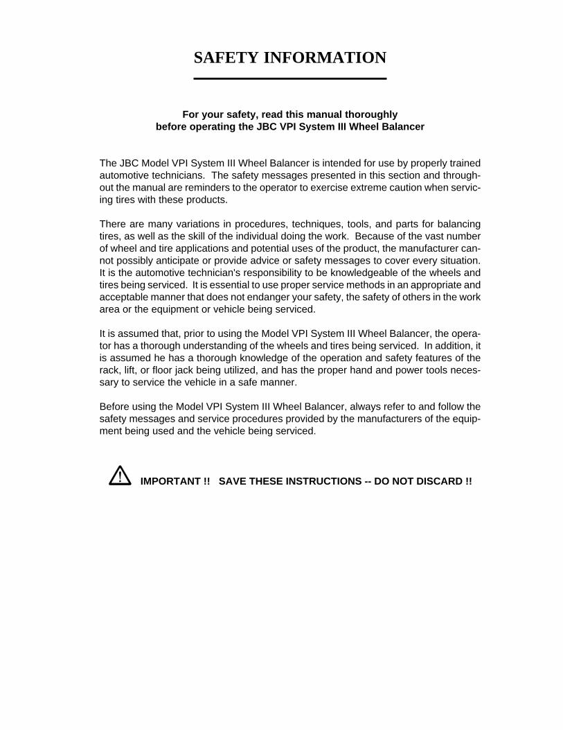
SAFETY INFORMATION
For your safety, read this manual thoroughlybefore operating the JBC VPI System III Wheel Balancer
The JBC Model VPI System III Wheel Balancer is intended for use by properly trainedautomotive technicians. The safety messages presented in this section and through-out the manual are reminders to the operator to exercise extreme caution when servic-ing tires with these products.
There are many variations in procedures, techniques, tools, and parts for balancingtires, as well as the skill of the individual doing the work. Because of the vast numberof wheel and tire applications and potential uses of the product, the manufacturer can-not possibly anticipate or provide advice or safety messages to cover every situation.It is the automotive technician's responsibility to be knowledgeable of the wheels andtires being serviced. It is essential to use proper service methods in an appropriate andacceptable manner that does not endanger your safety, the safety of others in the workarea or the equipment or vehicle being serviced.
It is assumed that, prior to using the Model VPI System III Wheel Balancer, the opera-tor has a thorough understanding of the wheels and tires being serviced. In addition, itis assumed he has a thorough knowledge of the operation and safety features of therack, lift, or floor jack being utilized, and has the proper hand and power tools neces-sary to service the vehicle in a safe manner.
Before using the Model VPI System III Wheel Balancer, always refer to and follow thesafety messages and service procedures provided by the manufacturers of the equip-ment being used and the vehicle being serviced.
IMPORTANT !! SAVE THESE INSTRUCTIONS -- DO NOT DISCARD !!
Page 2
IMPORTANT SAFETY INSTRUCTIONS
When using this equipment, basic safety precautions should always be followed,including the following:
1. Read all instructions.
2. Do not operate equipment with a damaged power cord or if the equipment has beendamaged - until it has been examined by a qualified authorized service technician.
3. If an extension cord is used, a cord with a current rating equal to or more than thatof the machine should be used. Cords rated for less current than the equipmentmay overheat. Care should be taken to arrange the cord so that it will not be trippedover or pulled.
4. Always unplug equipment from electrical outlet when not in use. Never use thecord to pull the plug from the outlet. Grasp plug and pull to disconnect.
5. To reduce the risk of fire, do not operate equipment in the vicinity of opencontainers of flammable liquids (gasoline).
6. Keep hair, loose fitting clothing, fingers and all parts of the body away from movingparts.
7. Adequate ventilation should be provided when working on operating internalcombustion engines.
8. To reduce the risk of electric shock, do not use on wet surfaces or expose to rain.
9. Do not hammer on or hit any part of the control panel with weight pliers.
10. Do not allow unauthorized personnel to operate the equipment.
11. Do not disable the hood safety interlock system or bypass the intended operation.
12. Use only as described in this manual. Use only manufacturer’s recommendedattachments.
13. Always securely tighten the wing nut before spinning the shaft.
14. ALWAYS WEAR SAFETY GLASSES. Everyday eyeglasses only have impactresistant lenses, they are NOT safety glasses.
15. Balancer is for indoor use only.
SAVE THESE INSTRUCTIONS

Page 3
John Bean VPI System III Operators Manual
TABLE OF CONTENTS
General Safety Instructions Page 21.0 Introduction Page 41.1 Safety Notice Page 41.2 Balancer Application Page 41.3 Specifications Page 51.4 Balancer Features Page 51.5 Standard Accessories Page 61.6 Optional Accessories Page 61.7 Dimensions Of The Machine Page 71.8 Installation Area Page 72.0 Installation Instructions Page 72.1 Component Installation Page 72.2 Hood Guard Installation Page 82.3 Width SAPE Arm Installation Page 82.4 Electrical Installation Page 82.5 Perform a User Calibration (see also page 21) Page 83.0 Terminology Page 94.0 Balancer Operation Page 104.1 Inspection Check list Page 104.2 Wheel Mounting Page 104.2.1 Mounting of Standard Wheels Page 104.2.2 Mounting of Light Truck Wheels Page 114.3 Mode Selection Page 114.3.1 Weight Placement Modes Page 114.4 Selecting Operator Preferences Page 124.4.1 Fine Balance Mode Page 124.4.2 Ounce /Grams Conversion Page 124.4.3 Inch/Millimeter Conversion Page 124.4.4 Selection of Operator A/B Page 124.5 Entering Rim Parameters Page 134.5.1 Distance and Diameter Entry Page 134.5.2 Rim Width Entry Page 134.5.3 Manual Parameter Entry Page 134.6 Correcting the Imbalance Page 144.7 Verifying Results Page 144.8 Vibration Problems Page 145.0 Matching Program Page 156.0 Optimization Program Page 177.0 Alu-S 2 Plane Program Page 187.1 Alu-S Single - Plane Program Page 198.0 Spoke Mode Page 209.0 Split Weight Mode Page 2110.0 User Shaft Calibration Page 2211.0 Width SAPE Calibration Page 2311.0 Full SAPE Calibration - Width, Distance and Diameter Page 2312.0 Explanation of "F" Codes Page 2513.0 Maintenance Page 2514.0 Trouble Shooting Page 25

Page 4
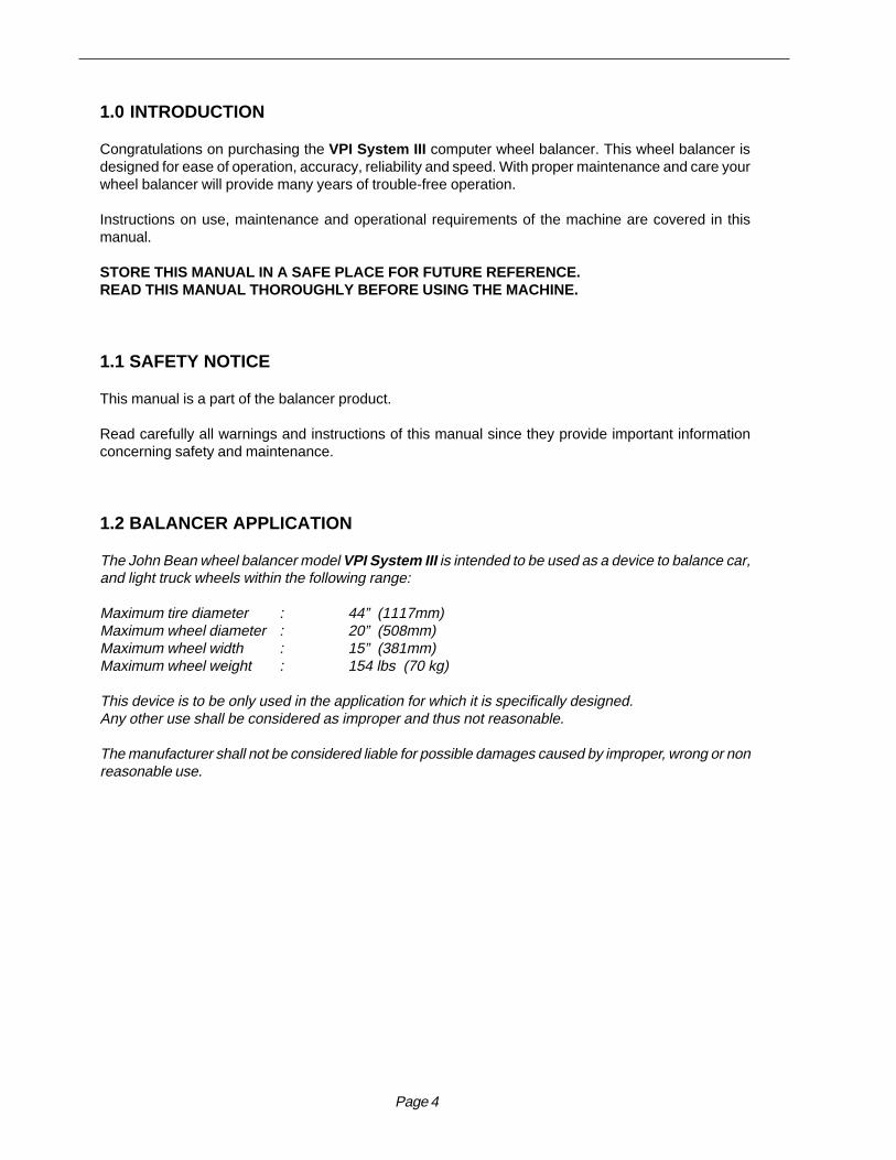
1.0 INTRODUCTION
Congratulations on purchasing the VPI System III computer wheel balancer. This wheel balancer isdesigned for ease of operation, accuracy, reliability and speed. With proper maintenance and care yourwheel balancer will provide many years of trouble-free operation.
Instructions on use, maintenance and operational requirements of the machine are covered in thismanual.
STORE THIS MANUAL IN A SAFE PLACE FOR FUTURE REFERENCE.READ THIS MANUAL THOROUGHLY BEFORE USING THE MACHINE.
1.1 SAFETY NOTICE
This manual is a part of the balancer product.
Read carefully all warnings and instructions of this manual since they provide important informationconcerning safety and maintenance.
1.2 BALANCER APPLICATION
The John Bean wheel balancer model VPI System III is intended to be used as a device to balance car,and light truck wheels within the following range:
Maximum tire diameter : 44” (1117mm)Maximum wheel diameter : 20” (508mm)Maximum wheel width : 15” (381mm)Maximum wheel weight : 154 lbs (70 kg)
This device is to be only used in the application for which it is specifically designed.Any other use shall be considered as improper and thus not reasonable.
The manufacturer shall not be considered liable for possible damages caused by improper, wrong or nonreasonable use.

Page 5
John Bean VPI System III Operators Manual
1.3 VPI System III SPECIFICATIONS
Computerized digital wheel balancer for car, light truckwheels.
Weight Imbalance Accuracy .05 oz / 1 gramWeight Placement Resolution ± .7 degreesWeight Imbalance Resolution: Roundoff Mode .25 oz / 5 grams Non-Roundoff Mode .05 oz / 1 gramMax. Shaft Weight Capacity 154 lbs / 70 kgMax.Tire Diameter 44" / 1117 mmRim Width Capacity 1.5"-15" / 38 mm - 381 mmMax. Tire Width 19” / 482 mmRim Diameter Capacity 8"-20"/203mm-508mmBalancing Cycle Time. 7 seconds or lessShaft Speed at calculation >200 RPMElectrical 230vac, 1ph, 50-60Hz, 3.2ARequired Work Area 62” x 67” (1574 x1702 mm)Shipping Weight, complete 325 lbs/147kgShipping Dimensions 52.75”h 41.5”w 37”dMachine Dimensions 54”h 51”w 48.5”dActual Weight with Accessories 309 lbs / 140 kgOperating Temperature Range 32-122F / 0-50C
1.4 FEATURES
ACCURACY• Weight placement accuracy to as low as ± .7°• Weight imbalance accuracy to 2 grams.• Self test check with every power up cycle.• Fast operator calibration.• Pre-programmed Error Codes indicate procedural
errors or safety concerns.
SPEED and DURABILITY• Automatic “3D” parameter entry. Simply touch the
SAPE arm to the inside of wheel and width gauge tothe outside, all parameters are automatically entered.
• Distance gauge auto stop feature.• Quick clamp speed nut reduces wheel mounting time.• Captured back spring eliminates having to handle the
backing spring.• Quick cycle time.• Automatic recalculation if weight positions are
changed. No need for re-spinning the wheel.• Common 40 mm diameter mounting shaft.• Weight pocket storage tray.• Easy-to-Read Data display.• Easy weight tray access.
SOFTWARE VERSATILITY• Both dual weight Dynamic and single weight Static
capability.• Stop-at-Top features simplifies weight imbalance lo-
cation• Match Balance program for reducing weight required.• Built-in spin counter for monitoring balancer
productivity.• Service code access to all Balancer electronic func-
tions for fast, easy diagnosis.• Operator selectable roundoff mode.• 5 Aluminum Modes• Alu-S mode• Hidden Weight (Spoke) mode• Split Weight mode

Page 11
John Bean VPI System III Operators Manual
FAILURE TO TIGHTEN WING NUT SECURELYMAY RESULT IN SERIOUS PERSONAL INJURY.
DO NOT USE A HAMMER TO TIGHTEN THEQUICK NUT.
TO RELEASE THE QUICK NUT, UNSCREW AFEW TURNS TO REDUCE THE AXIAL PRES-SURE, THEN PRESS THE UNLOCK LEVER ANDSLIDE AWAY FROM THE SHAFT.
5. Check that the wheel rotates true by turning the wheelseveral revolutions while noting any excessive runout.
4.2.2 CENTERING LIGHT-TRUCK WHEELS
An optional offset spacer may be required for some lighttruck wheels and reverse-offset wheels that must bemoved away from the balancer mounting flange. Theextension adaptor is often used with the 5-1/4 inch di-ameter light truck cone.
Install the spacer on the mounting flange, then mountthe wheel, using the front cone method (Figure 13)
Figure 13
4.3 MODE SELECTION
The majority of balancing takes place in the default 2-plane dynamic mode which is displayed as "2 PL"(location 1). Hammer-on clip weights will be placed onboth inside and outside of the rim edge. If required,select an optional weight placement mode by pressingthe Mode button until the appropriate placement modeis displayed.
4.3.1 WEIGHT PLACEMENT MODES
Before spinning the wheel (although it may be done af-terwards) choose the appropriate balancing mode forthe wheel. To select the various placement modes pressthe Mode button until placement LEDs indicate desiredplacement position.
The balancing modes available are:
A. DYNAMIC (two planes), suggested for all steel rims.In this case the wheel weights must be clipped onto therim edges. This function is selected as a default andthe LEDs corresponding to the wheel weight locationare lit on (Figure 15).
B. STATIC (single plane - Figure 16). Suggested fornarrow rims (3" or less). Use a single corrective weightplaced in the center or inner edge of rim as illustrated inFigure 16.
Figure 14
Figure 15
Figure 16
!
Figure 12
Mode Button
Indicator LEDs
1234123412341234
Static 1Static 2

Page 12
C. ALUMINUM MODES. Balancing using a combina-tion of hammer-on and adhesive weights as shown inFigures 17 thru 21.
Figure 17 ALU 1
Figure 18 ALU 2
Figure 19 ALU 3
Figure 20 ALU 4
Figure 21 ALU 5
TO RETURN TO THE DYNAMIC PROGRAM FROMANY OF THE ALU PROGRAMS, JUST PRESS Can-cel/Stop.
4.4 SELECTING OPERATOR PREFERENCES
4.4.1 FINE BALANCING MODE
This balancer measures with the maximum precisionavailable all the time, 1g / 0.05 oz, however values be-low 5g / 0.25 oz are shown as zero while in the normaloperating mode. Values exceeding 5g / 0.25 oz arerounded to the amount of the nearest commercial wheelweight.
Press the Fine Mode button (number 5 on page 9) totoggle the display resolution between 5g / 0.25 oz and1g / 0.05 oz.
4.4.2 OUNCE/GRAMS CONVERSION
When the machine is first turned on it is preset to dis-play the imbalance in ounces.If the display in grams is desired, press the F buttonfollowed by the UP or Down arrow button until “F 3” isdisplayed”. Press “ENTER”.Repeat the procedure for converting back to ounces.
4.4.3 RIM DIAMETER IN MILLIMETERS
The rim diameter is normally displayed in inches, how-ever if the value in millimeters is desired, press the Fbutton followed by the UP or Down arrow button until“F 7” is displayed”. Press “ENTER”.Repeat the above operation to convert back to inches.
Example: “dIA ICH” = inches“dIA ---” = millimeters
4.4.4 OPERATOR SELECTION
Select the desired operator designated A,B,C,or D. TheSystem III Balancer can store wheel parameters of fouroperators. The Operator button toggles between the fouroperators with each depression.

Page 13
John Bean VPI System III Operators Manual
4.5 ENTER RIM PARAMETERS
4.5.1 Rim Distance (offset) and Diameter - Movethe rim offset arm to the inside edge of the rim,touch the pointer to the rim edge, touch the tip ofthe width arm to the outside rim edge whereweights will be placed as illustrated in Figure 22.Hold arms steady for about a second. The beeperwill sound when the parameter values are calcu-lated and entered automatically. Return the armsto its home rest position on the balancer. Do notallow the measurement arms to "dangle".
Figure 22
4.5.2 Manual Parameter EntryIn the event of automatic gauge failure, ANYparameter value can be input manually.
4.5.2.1 Manual Distance Entry - Move the dis-tance gauge arm to touch the inner edge of thewheel where weights are to be placed and observethe reading on the scale of the distance gauge.Press manual Wheel Parameter button (#11 page9) followed by pressing the UP or Down arrowbutton until value is displayed in the left displaywindow.
4.5.2.2 Measure Rim Width Manually using rimwidth calipers. Measure wheel where correctiveclip-on weight would be applied, Figure 23. Enterthe measured width by pressing the Parameterbutton followed by the UP or Down arrow buttonuntil the desired value appears in the right display.
Figure 23
4.5.2.3 Manual Rim Diameter Entry - Select theManual Parameter button (#11 page 9). Read therim diameter marked on the sidewall of the tire(Figure 24). Enter the measured rim diameter bypressing the Parameter button followed by theUP or Down arrow button until the desired valueappears in the right display.
Figure 24
NOTE: For a more precise balancing of perfor-mance wheels, an “ALU-S” Mode is available forprecision determination of wheel parameters. Thisfeature allows exacting placement of correctiveweights as well. See Page 18 for detailed instruc-tions.
NOTE: The parameter arms must be in the Homerest position when the balancer is powered up.This establishes the arm starting position.

Page 14
4.6 CORRECTION OF THE IMBALANCE
NOTE: Before spinning the wheel make sure propereye protection is worn by all personnel in the vicinity ofthe balancer.
A. Spin the wheel by lowering the wheel guard or bypressing the Enter button. When the balancing cycleis completed the wheel will stop automatically and theimbalance values will appear on the LED’s.
NOTE: DO NOT USE THE FOOT OPERATED SHAFTLOCK AS A BRAKE, IT IS INTENDED TO BE USEDONLY TO PREVENT SHAFT ROTATION WHILEPLACING CORRECTIVE WEIGHTS.
B. Read the imbalance value on the outer display. Val-ues are displayed in ounces but can be displayed ingrams if required and are automatically rounded to thenearest commercial wheel weight.
4.6.1 PLACING THE CORRECTIVE WEIGHTRaise the wheel guard and turn the wheel until the dis-plays of the outer plane imbalance position indicatorare illuminated green. A tone will sound indicating topdead center. Apply the wheel weight at twelve o’clockposition. Use the foot operated shaft lock to preventshaft rotation while placing weights.
C. Correct the inner plane in the same manner.
4.7 VERIFICATION OF THE RESULTS
Lower the wheel guard to spin the wheel again andcheck that the readout is “0.00” “0.00” If a residualimbalance is displayed:
A. Check the rim parameters, if entered value is incor-rect, correct as needed. Imbalance values will be re-computed after re-spinning wheel.
B. Check if the balancing mode selected is the mostappropriate. If not, choose the right mode and re-spin.
C. The wheel weight could have been placed at a wrongposition. To check this, position the wheel at the cor-rection position for the outer plane. If the wheel weightpreviously attached is in sector ‘L’ or ‘R’ ( Figure 25),move the wheel weight up about 1” (2.54cm).If the wheel weight is in sector ‘D’ cut a piece of thewheel weight of an approximate value correspondingto the value shown on the right display, or replace thewheel weight with a lighter one.If the wheel weight is in sector ‘U’ add a weight of valueindicated by the display or replace the wheel weightwith a heavier one. Repeat the same operation for theinner plane.
NOTE: If this situation is repeated, your machine maybe out of calibration and a calibration operation mightbe required as instructed on page 22.
D. If an ALU function was selected ensure that the wheelweights have been placed in accordance to the pro-gram chosen.
E. Check that the quick nut is tight and that the wheel isnot slipping against the backing collar.
F. Check that the wheel and adaptors are clean.
Figure 25
4.8 VIBRATION PROBLEMS
If vibration is still present after balancing, check the fol-lowing possible sources of vibration:
1. Stones caught in the tire tread.2. Tire slippage on the wheel.3. Incorrectly mounted wheel.4. Imbalanced wheel covers.5. Excessive radial or lateral runout in the tire or
wheel.6. Damaged wheel bolt holes.7. Worn universal joints.8. Imbalanced brake rotors or drums.9. Worn or damaged balancer accessories.

Page 15
John Bean VPI System III Operators Manual
5.0 TIRE MATCHING PROGRAM - F90
Tire matching assists the user in determining the bestpossible mating of the tire and rim. The mating of tireand wheel normally allows the least amount of addi-tional weight required for balancing and total runout.
The matching program is helpful when:• Excessive radial runout is noticed.• The balancer calls for weights in excess of 2 oz. on
either plane in the Dynamic mode.
The VPI System III computer wheel balancer featuresa matching program capable of two levels of resolution:
Dynamic, to rotate and reverse the tire on the rimfor optimum rim and tire matching.Static, when the tire has an ornate sidewall or di-rectional tread and cannot be reversed on the rim.
INSTRUCTIONS:
1. Press the "F" button followed by pressing the UP orDown arrow button until the display reads "F" “90”,release the "F" button.
When activated the machine displays "--- ACH---" forone second followed by "PUT VAL tOP". This instructsthe operator to rotate the wheel so the inflation valve isat 12 o'clock. See Figure 26. Press "F" to store thevalve position, the display will then read "ACH SPN 1 ".
NOTE: THE F BUTTON CAN BE PRESSED MORETHAN ONCE, EVERY TIME THE F BUTTON ISPRESSED, THE VALVE POSITION IS REMEMBEREDBY MACHINE AS A REFERENCE POINT.
2. Lower the wheel guard to spin the wheel, when theshaft reaches the balancing speed, the display reads"--- ACH --- " accompanied with a short beep.
3. After spinning the shaft brake engages and the dis-play reads "tur tir---" and "CrS tOP---" alternatively.
(1) The operator should turn the wheel and mark an Xat the 12 o'clock when the valve is at the 6 o'clock posi-tion. Figure 27
(2) Remove the wheel assembly from the balancer anddeflate and rotate the tire on the rim so the valve pointsto the cross mark on tire as shown in Figure 28
4. After inflating the tire and remounting on shaft, pressF Button. The machine displays "PUT VAL tOP" again.Operator should turn the wheel so the valve is at 12o'clock. Press the "F" button to program the valve posi-tion.
Figure 26 - Step 1, valve top, press "F"
Figure 27 - Step 2, valve at bottom,mark top of tire with X, press "F"
Figure 28 - Step 3, rotate tire on wheel so the valve andX mark line up. Rotate assembly to TDC, press "F".

Page 16
NOTE: THE "F" BUTTON CAN BE PRESSED AS OF-TEN AS NECESSARY, WITH EVERY PRESS THEMACHINE UPDATES THE MEMORY OF THE VALVEPOSITION.
5. The machine displays "ACH SPN 2 ". Lower thewheel guard to spin the wheel, when the shaft reachesthe balancing speed, machine displays "--- ACH ---"along with a beep.
6. Once the spin cycle is complete, the display reads"CAL CUL ACH" for one second. Machine calculatesthe results based on the previous two spins.
After calculation the machine displays the unbalancecontributions of rim and tire in percentages of total un-balance to allow operator to evaluate the quality of thetire or rim. For example, if the total unbalance is 4.5 ozin which the rim unbalance measured is 3 oz and tireunbalance is 1.5 oz. In this case, the rim unbalance is67% of total unbalance and tire is 33%. Machine dis-plays “ r “ “ 67” and “ t “ “ 33” alternatively until theoperator presses the “F” button. This function allowsoperator to check the unbalance contribution of the rimand tire. If someone has too large unbalance, operatorcan stop the procedure and change the bad rim or tire.
From this point, there are three possible procedures toconclude the match balance routine. These 3 proce-dures are quite different depending on the results ofcalculation.
Procedure 1The imbalance measured in spin 2 has been reducedto an acceptable amount, less than 2 oz, and it will notbe necessary to continue match balance. The displayreads "ACH FIN ISH" for one second, and then pro-ceeds to the normal two-plane balancing mode and dis-plays the weight imbalance amount and its position forboth planes.
Procedure 2Due to a large amount of remaining imbalance the op-erator can continue match mount. Machine displays"CRS CRS R" and "TUR TIR ---" alternatively. This in-structs the operator to turn the wheel and make a doublecross mark (XX) on the right side of the tire at 12 o'clockposition when the right center position LED turns togreen. See Figure 29.
NOTE: IF YOU DO NOT INTEND TO CONTINUE MINI-MIZATION, YOU CAN PRESS THE CANCEL/STOPBUTTON
Figure 29
Figure 30

Page 17
John Bean VPI System III Operators Manual
If the Cancel/Stop Button is pressed now, machine dis-plays "Qit Qit Qit" for one and half second to remindoperator whether he/she wants to quit optimization ornot. If one presses Cancel/Stop Button immediately, theprogram goes to procedure 1. If not, after one and halfsecond, machine returns to the optimization procedure.
To continue with optimization: Deflate the tire and thenturn the valve to point the XX mark on the tire. Remounttire/wheel onto shaft, press "F" when ready to continue.
1. The machine displays "PUT VAL tOP". Turn thewheel so the valve is at top position. (12 o'clock) andthen press F Button. The machine stores the valve po-sition. See Figure 30.
2. The machine displays "SPN 3 ". Lower wheel guardto spin shaft. Machine displays "ACH SPN 3 ".
3. Display will read "--- ACH ---" for one second. Bal-ancing results are checked whether or not the match-ing balancing has been achieved and will display “ACHCHC ---” for one second.
4. There are two results that could been given by theprevious step:
1 - Match Balance failure. Machine displays:"FAI L " for one second and then goes to idle state.
2 - Match Balance is successful. Machine displays:"ACH FIN ISH" for one second and then goes tonormal two plane balancing mode. Machine displaysthe recalculated weights and their position takingthe matching results into account.
Procedure 31. Machine displays "CRS CRS L" and "FLP tir ---"alternatively. When the left center position LED turns togreen this instructs the operator to turn the wheel andmark a XX on the left side of the tire at 12 o'clock posi-tion.
2. If the tire cannot be flipped, press the Cancel/StopButton to force machine to procedure 2.
Calculations may not allow continuation of the match-ing process. If this is the case, machine displays "NONO NO" for one and half second. If the operator doesnot respond the machine returns to above state afterone and half second.
If the Cancel/Stop Button is pressed within one and halfsecond, machine will display "Qit Qit Qit" for one andhalf seconds indicating cancelation of optimization re-turning the machine to normal balancing modes.
If optimization is to be continued with flipping tire, pro-ceed as described below.3. Deflate the tire then flip, turning the valve to point theXX mark on the tire (as in procedure 2).
4. Inflate the tire and mount it to shaft again. Press the“F” Button.
5. The machine displays "PUT VAL tOP". Turn thewheel to make valve at top position. (12 o'clock) andthen press "F" button. The machine will store the valveposition.
6. The machine displays "SPN 3 ".
NOTE: THE F BUTTON CAN BE PRESSED AS OF-TEN AS NECESSARY, WITH EVERY PRESS THEMACHINE UPDATES THE MEMORY OF THE VALVEPOSITION.
7. Lower the wheel guard to spin the shaft. Machinedisplays "ACH SPN 3 " while collecting data. Do notdisturb the machine while it is acquiring data.
8. When balancing is complete, the machine displays"--- ACH ---" for one second. Machine processes thebalancing results to check whether or not the matchingbalancing has been achieved. Balancing results arechecked whether or not the matching balancing hasbeen achieved and will display “ACH CHC ---” for onesecond.
9. There are two results could been given by the previ-ous step.
1. Matching balancing failure. Machine displays:"FAI L " for one second and then goes to idle state.
2 - Match Balance is successful. Machine displays:"ACH FIN ISH" for one second and then goes tonormal two plane balancing mode. Machine displaysthe recalculated weights and their position takingthe matching results into account.
6.0 OPTIMIZATION ROUTINE- F91
The Optimization Routine is very similar to that of theMatch Mount Program (F90). The main difference isthat operation begins with a bare rim instead of a rim-tire assembly. Follow instructions as detailed for in chap-ter 5.0 for F90.

Page 18
7.0 ALU-S 2-PLANE MODE
This is a mode similar to ALU mode 2 and 3. The differ-ence is that the distance and width parameters are ac-curately defined for a more exacting weight placement,therefore improving the likelihood of a single spin bal-ance. Follow the procedures below:
1. Press the Alu-s button to activate the ALU-S 2-PLmode, the display will read " --- ALU - S 2-PL" whenactivated. Each depression of the Alu-s button will togglebetween a 2-plane mode and a single plane mode.
2. Extend the rim offset gauge arm and touch the posi-tion of the left weight position. See Figure 31. Thedisplay will read “d - I”. The high tone will sound whendimension is entered. Return the gauge arm to the restposition, a low pitch tone will indicate when it is OK toproceed. The width arm is not used in this procedure.
3. Move the parameter arm to the right weight posi-tion, the machine displays “d - 2” as the arm is moved.See Figure 32. The high tone will sound when dimen-sions are entered. Return the gauge arm to the restposition, a low pitch tone will indicate when it is OK toproceed.
4. Lower the wheel guard or press “Enter” to spin thewheel. The display will read “ALU” during the spin cycle.
5. After spinning, The wheel/tire assembly will stop withthe outside (right) imbalance plane at top. The displayreads both the left and right plane imbalance weightand position.
6. Extend the gauge arm to locate the outer place im-balance. The right display shows the weight amount tobe applied, the left display shows the distance the gaugearm has to travel to get to the correction plane. Thesape arm will lock when the correct position is reached,at the same time the display will read “0“ when the properposition is attained. A “beep” will accompany the lockposition. Apply the weight amount indicated using thetape weight applicator mounted on the SAPE exten-sion.
Return the gauge arm to its home position.
7. The left plane correction weight will be applied nextas in step 6 above. The steps outlines are:- Extend the arm until the arm locks into position.- Position the wheel in the weight application position- Apply the displayed weight.
NOTE: RETURNING THE GAUGE ARM TO THE“HOME” POSITION TOGGLES BETWEEN THE LEFTAND RIGHT CORRECTION PLANE.
NOTE: TO EXIT ALU-S MODE AND RETURN TOTWO PLANE DYN (DYNAMIC) MODE PRESS “MODE”BUTTON. THE MACHINE DISPLAYS "ALU OFF" FORONE SECOND AND THEN ENTERS IDLE STATE INTHE 2-PL DYN MODE
NOTE: INSPECT THE RIM AND AVAILABLEWEIGHTS AND USE GOOD JUDGEMENT IN YOURSELECTION. WEIGHTS SHOULD NOT INTERFEREWITH ANY SUSPENSION PARTS OR MAKE CON-TACT DURING ROTATION. IF A WEIGHT DOESMAKE CONTACT, USE AN ALTERNATE LOCATION ANDSELECT AN APPROPRIATE MODE.
Figure 31
Figure 32

Page 19
John Bean VPI System III Operators Manual
7.1 ALU-S SINGLE-PLANE (STATIC)MODE
This is a mode similar to a conventional Static mode.The difference is that the distance and diameter param-eters are accurately defined for a more exacting weightplacement, therefore improving the likelihood of a singlespin balance. Follow the procedures below:
1. Press the Alu-s button to activate the ALU-S 1-PLmode, the display will read " --- ALU - S 1-PL" whenactivated. Each depression of the Alu-s button will togglebetween a 2-plane mode and a single plane mode.
2. Extend the rim offset gauge arm and touch the posi-tion of the desired single weight position. See Figure33. The display will read “d - I”. A tone will sound whendimension is entered. Return the gauge arm to the homerest position, a low pitch tone will indicate when it is OKto proceed.
NOTE: The width arm is not used in this procedure.
3. Lower the wheel guard or press “Enter” to spin thewheel. The display will read “ALU 1 PL” during the spincycle.
4. After spinning, The wheel/tire assembly will stop withthe imbalance plane at top. The display reads both theimbalance weight and position.
5. Extend the gauge arm to locate the place of imbal-ance. The right display shows the weight amount to beapplied, the left display shows the distance the gaugearm has to travel to get to the correction plane. The sapearm will lock when the correct position is reached, at thesame time the display will read “0“ when the proper posi-tion is attained. A “beep” will accompany the lock posi-tion. Apply the weight amount indicated using the tapeweight applicator mounted on the SAPE extension.
6. Perform a check spin if desired
NOTE: TO EXIT ANY ALU-S MODE AND RETURN TOTWO PLANE DYN (DYNAMIC) MODE PRESS “MODE”BUTTON. THE MACHINE DISPLAYS "ALU OFF" FORONE SECOND AND THEN ENTERS IDLE STATE INTHE 2-PL DYN MODE
NOTE: INSPECT THE RIM AND AVAILABLE WEIGHTSAND USE GOOD JUDGEMENT IN YOUR SELECTION.WEIGHTS SHOULD NOT INTERFERE WITH ANY SUS-PENSION PARTS OR MAKE CONTACT DURING RO-TATION. IF A WEIGHT DOES MAKE CONTACT, USEAN ALTERNATE LOCATION AND SELECT AN APPRO-PRIATE MODE.
Figure 33

Page 20
8.0 SPOKE BALANCING MODE
A standard dynamic balance places compensation weightin two planes, inner and outer, at the top dead center 180degrees of each plane of calculated imbalance. Sometimesthe outside weight placement may be unsightly on a cus-tom wheel. See Figure 34.The Spoke Mode is designed to “hide” outer plane correc-tive weight by placing the required weight behind selectedspokes in order to retain the esthetic appeal of the wheel.
1. Press the Alu-s/Spoke button until “SPO” is displayed,the display will read " SPO " when activated.
2. Enter left plane distance using the SAPE as you woulda dynamic 2-plane or ALU-S balance.
3. When machine displays “d - 2” move the SAPE arm tothe right position plane where weight will be placed.
4. Press Enter, or, lower hood guard. The display will read“SPO” while spinning. After Braking to a stop rotate theshaft to the inside plane top dead center position indicatedby the center green LED. Extend the SAPE until the rightreading says “0”, place indicated weight in the position di-rected by the SAPE.
5. Rotate the wheel to the outside plane top dead centerposition indicated by the center green LED, press the "F"button to indicate top dead center.
NOTE: Mark the tire to assist in referencing the correctiveweight top dead center.
6. The display will read "SPO I “. Locate the first spokenearest to top dead center and rotate the wheel so thatspoke is at top dead center. See Figure 34. Press F tostore first position.
7. The display will read “SPO 2 “. Locate the secondclosest spoke to top dead center and rotate the wheel tothe top dead center position, press F Button again to storethe position. See Figure 35.
8. The display will read “P -2” on its left window and thebalance weight amount in right window. Place the weightamount displayed at “position 2” behind the spoke, thenrotate the wheel to locate position 1. See Figure 36.
9. When position 1 is located, the balancer will beep. Thedisplay will read “P -1” in the left window and the weightamount on right window. Place the weight amount dis-played at “position 1” behind the spoke.
10. Perform a check spin if desired.
Figure 34
Figure 35
Figure 36
Figure 37
X
XX

Page 21
John Bean VPI System III Operators Manual
9.0 SPLIT WEIGHTS - P92
The “Split Weight” function is used to split one largeweight to two smaller weights with 60% of original weightand 33.6° away each direction from the original position.For instance, if the original unbalance weight is 3 oz, theweight is split into two 1.75 oz weights and placed 56.4°and 123.6° from the original larger value located top deadcenter at 90 degrees. The minimum weight to activatethis function is 2 oz. The procedure is described below.See Figure 38.
1. After balancing, the weight amounts are displayedin left and right windows.
2. Enter F92, machine will display “SPL -L- “ or “SPL-R-“ meaning which plane should be split.
3. Press the “STOP” button alternately to toggle be-tween the left and right plane.
4. Once the desired plane is chosen, press the "F"button. The machine splits the weight into two parts.The split weight is 60% of the original weight. Theposition is 33.6° from each side the original posi-tion.
5. If the displayed weight is less than 2 oz (56.7 grams),the machine will display “ NOT AVL” for one sec-ond, and then resumes the normal display.
6. Pressing “STOP” cancels the split weight modeand operation returns to normal. The operator cancheck if the position of original weight is betweenthe two smaller weights.
7. Pressing the “STOP” button again, returns the ma-chine to idle mode without weight amount or posi-tion display.
8. For a check spin, lower the hood guard or press“SPIN” button.
Figure 38

Page 22
Figure 39
Figure 40
Figure 41
10.0 USER CALIBRATIONF14 Shaft Calibration
The VPI System III Balancer features a user calibrationprogram which requires only a few minutes to complete.Perform this procedure when the balancer has beenmoved, disturbed, or whenever accuracy is questioned.Occasional field calibration will ensure years of reliableservice.
Follow these 3 simple steps for shaft calibration:
1. Activate Calibration.Press the F Button then press the UP/Down buttons(Figure 39) until the display reads "F" “14”, press EN-TER• Once F14 activates, the display will read
"CAL" " GAN" for one second.• The display will then read "SPN" " 1 ".
2. Spin bare shaftLower the wheel guard or press ENTER to spin the shaft.See Figure 40.• Displays "CAL" " 1 " as the machine is collecting
data and performing calculations. After taking data,the shaft is automatically braked to a stopped.
• The display will read "SPN" " 2".
3. Spin shaft with calibration slug on the left side.Mount calibration slug to inside edge of shaft mountingplate as shown in Figure 41.• Lower the wheel guard or press ENTER to spin the
shaft with slug.• Displays "CAL" " 2" as the balancer is doing its
calculations. When complete, the shaft is automati-cally braked to a stop.
• The display will read "CAL" "FIN " for one secondwhen this step of calibration is FINished.
• If for some reason the calibration detected an error,the display will read: "---" "---" after the shaft brakes.
NOTE: THE BALANCER WILL NOT FUNCTION UN-TIL A VALID CALIBRATION HAS BEEN PERFORMED.AN ERROR MESSAGE WILL BE DISPLAYED IN THEEVENT PROBLEMS OCCUR DURING THE CALIBRA-TION PROCESS.
SHAFT CALIBRATION IS COMPLETEContinue to next page for parameter arm
calibration instructions.
Up / DownKeys
F KeyEnter Key

Page 23
John Bean VPI System III Operators Manual
11.0 WIDTH PARAMETER CALIBRATIONF79 Calibration of Width SAPE only
1. Press and release the “F” key toggle the “UP /DOWN” arrow keys until “F” “79” is displayedand press enter to activate function of F79. Onceactivated the display will change to “CAL” “SAP”E-2” for 1 second, then the display will changeto“DIS” “tO” “FLA”.
2. Pull the distance gage to the outside flange of thebacking collar, use the flat head of the calibrationweight as an index. After a short beep, the machinedisplays “bAC H POS”. Return the arm to thsrest postition. See Figure 42.
3. The display will read “to FLA NGE”, Touchthe tip of the width gauge to the backing collar andhold it for one second or press the “F” button(Figure 42a). The display will change to “bAC “H’‘POS” followed by a tone. Return the SAPE arm tothe home position.
4. Display will then change to “tO” “CAL” “SLG”.Screw the calibration weight onto the outside of theflange. Touch the tip of the width gauge to the tipof the calibration slug and hold it for one second orpress the “F” button (Figure 43). The display willchange to “SAP” “E-2” “FIN” for one secondfollowed by a tone indicating a successful calibra-tion. Unit will then go into an idle state.
WIDTH SAPE CALIBRATION COMPLETE
11.1 PARAMETER CALIBRATIONF80 Distance, Diameter and Width SAPE Calibra-tion
1. Make sure the SAPE arm is in the home positionas shown in (Figure 44).
NOTE: WEIGHT TRAY MUST BE INSTALLED
2. Activate the gauge calibration program. Press andrelease the F key and toggle the “UP / DOWN”button until 80 is displayed on right display windowand press enter.
3. The right display will read "CAL” “3-D” “SAP" forone second (Do not move the arm at this point)this means CALibration SAPE. Then it displays"SAP” “OUT” “FUL”. The SAPE calibrationprocedure is activated.
Figure 42a
Figure 43
Figure 44
Figure 45
Figure 42

Page 24
4. Gently pull the SAPE arm OUT until it is FULLYextended, (Figure 45) hold it steady for about 1second, a tone will sound.
5. Display will read “BAC” “H” “POS” followed by abeep. Return the arm to the home position. Fig. 44.
6. Display changes to “dIA” “ -18” “POS”.
7. Gently pull the SAPE out and rest the arm of theSAPE gauge on the inner part of the bell housingas shown in (Figure 46). A tone will sound and thedisplay will change to “BAC” “H” “POS”.
8. Return the arm to the home position, Figure 44.The display will change to “dIA” “42.1” “POS”.
9. Locate the Calibration Weight. Place the calibra-tion weight with the large end oriented on the bellcollar as shown in Figure 47. Extend the SAPEarm outward and rotate the extension to just touchthe end of the calibration weight as shown in Figure47. A tone will sound and the display will change to“BAC” “H” “POS”. Return the SAPE arm to thehome position.
10. The display will change to “SAP” “E-1” “FIN” forone second then changes to “DIS” “tO” “FLA”.
11. Pull the distance gage to the outside flange of thebacking collar, use the flat head of the calibrationweight as an index. After a short beep, the machinedisplays “bAC H POS”. See Figure 47a.
12. Touch the tip of the width gauge to the backingcollar and hold it for one second or press the “F”button (Figure 48). The display will change to “bAC“H’ ‘POS” followed by a tone. Return the SAPEarm to the home position.
13. Display will then change to “tO” “CAL” “SLG”.Screw the calibration weight onto the outside of theflange. Touch the tip of the width gauge to the tip ofthe calibration slug and hold it for one second orpress the “F” button (Figure 49). The display willchange to “SAP” “E-2” “FIN” for one secondfollowed by a tone indicating a successful calibra-tion. Unit will then go into an idle state.
FULL SAPE CALIBRATION COMPLETE
Figure 46
Figure 47
Figure 48
Figure 49
Figure 47a

12.0 EXPLANATION OF PROGRAM CODES
Various functions and features can be programmed toenhance operation. These programs are referred to as“F Codes”. Activate the “F Code” programs by pressingand holding the F Button while depressing the up/downarrow buttons or by turning the shaft until the desirednumber is displayed on the right display window. UserCodes are explained as follows:
F1 Toggle between normal and fine mode.F3 Toggle switch between gram and ounce displayF4 Calibrate with adapter unbalanceF7 Toggle switch of millimeter and inch for diameter
measurementF12 The balancer has 4 counters that keeps track of total
number of cycles for a certain parameter. The bal-ancer will automatically cycle through the countersafter F12 is pressed. The order of the counters are:
1. Display “Ctr ALL” for one second.Counter number of all spins.
2. Display “Ctr CAL” for one second.Counter number of spins since last calibration.
3. Display “Ctr SrV” for one second.Counter number of service spins.
4. Display “Ctr USR” for one second.Counter number of user spins.
F14 Shaft User Calibration by userF18 ALU-S 2-plane mode (press balancing mode button
to exit and back to DYN mode)F19 ALU-S 1-plane (static)mode (press balancing mode
button to exit and back to DYN mode)F43 Read or reset operator counters, reads or allows
reset of all four operators. (A, B, C, D)
F44 Read or reset productivity of user. Display counternumber of default user only.
F53 Display test
F79 Calibration of the width SAPE.
F80 Calibration of Distance and Diameter SAPEF90 Tire Matching ModeF91 Optimization
13.0 MAINTENANCE
BEFORE ANY MAINTENANCE OR RE-PAIRS ARE ATTEMPTED THE MACHINEMUST BE DISCONNECTED FROM THEELECTRIC SUPPLY.
This balancer does not require any special maintenance,but the following precautions are required:
A. Periodically wash all plastic parts with a glasscleaner. Wipe with a dry cloth.
B. Clean all adapters regularly with a nonflammable liq-uid detergent all. Lubricate with a thin layer of oil.
C. Periodically perform a routine calibration as outlinedon pages 22, 23 and 244 of this manual.
14.0 TROUBLE SHOOTING
TROUBLE CAUSE REMEDYWhen turning the machine on, No electric power Check the input voltagethe displays do not light Defect in the electric/electronic system Call the Equiserv service center
for assistance
The machine gives random readouts. Machine unstable on the floor Check that machine is stableWater in the tire Remove water from tire.Loose adaptor Tighten the adaptor firmlyDefective electronic board Call the Equiserv service center
for assistance
The machine does not stop after Defective electronic component Stop using the machine immedibalancing cycle ately and call the Equiserv service
center for assistance
The balancer is slow to display when This machine performs a self-test routine This is a normal characteristicpowering machine up. on start-up. There will be a delay of several of the machine
seconds before the display is activated.
If the parameter arm(s) ceases to Malfunction of the Parameter arm(s) from Replace the Parameter arm(s) orproperly measure values either a failure of the electrical system manually enter the parameterscausing machine lockup. or harness connection failure. to continue operation.
!

Form 5819-5...pn ZEEWB502A....01/28/2003..wdc... copyright 2001-2003 Printed in the USA
Notice: The information contained in this document is subject to change without notice. John Beanmakes no warranty with regard to this material. John Bean shall not be liable for errors contained hereinor for incidental consequential damages in connection with furnishings, performance, or use of thismaterial.
This document contains proprietary information which is protected by copyright and patents. All rights arereserved. No part of this document may be photocopied, reproduced, or translated without prior writtenconsent of John Bean.
is a trademark of John Bean and Snap-on Incorporated
USAJohn Bean309 Exchange AvenueConway, Arkansas 72032Tel.: (800) 362-8326 or (501) 450-1500Fax: (501) 450-1585
FRANCEJohn BeanSnap-On Equipment FranceZ.A. Du Vert Galant15, rue de la GuivernoneBP 717595310 Saint Ouen L’AumoneTel: (33) 1-3448-5878Fax: (33) 1-3448-5879
UNITED KINGDOMSnap-On Equipment Ltd.John Bean Equipment GroupOldmedow RoadKings LynnNorfolkPE30 4JW
CANADAJohn Bean6500 Millcreek DriveMississauga, OntarioCanada L5N 2W6Tel: (905) 814-0114Fax: (905) 814-0110
JBC GERMANYGeschaeftsbereich der Snap-on Equipment GmbHWerner-von-Siemens-Str. 2D-63419 PfungstadtDeutschlandTel: +49 (0) 6157 12 600Fax: +49 (0) 6157 12 601Website: www.johnbean.de
LATIN AMERICASnap-on Tools International, Ltd.2801 80th StreetKenosha, WI 53143Tel: (262) 656-5003Fax: (414) 656-1403