Embed Size (px)
Citation preview

------
PAYER OR CH ISTMA
TREE '" '"
/ /
/
-- ~/,/
~ /::.,....--- ,
,/ ,/
-~/------ '-----""'--------""'"'-- l'.:...~~=-. ~----~ / / " "
/ ~ ~
/
aID----- ",) -----TheUniversityofGeorgia
College of Agriculture Cooperative Extension Service

Sprayers for Christmas Trees by
Paul E. Sumner Extension Engineer
The equipment used for applying insecticides, fungicides, herbicides and foliar colorants can be classified as sprayers. Christmas trees sprayers can be three point hitch or trailer type units. These sprayers can be either hydraulic boom or air blast, with hydraulic boom sprayers being the most preferred type of application equipment. Boom sprayers get their name from the arrangement of the conduit that carries the spray liquid to the nozzles. Booms or long arms on the sprayer extend across one, two, or between rows as the sprayer passes over the field. Air blast sprayers are being used more for applying insecticides or fungicides. Air blast sprayers have a boom like the hydraulic sprayer except the blast of air is the carrier for the chemical. Growers are getting better penetration into the tree structure with air blast sprayers. Figure 1 shows equipment necessary for a properly working hydraulic boom sprayer. Each component is important for efficient and effective application. An air blast sprayer has similar components.
TANKS
Sprayer tanks are available in many sizes, shapes and materials. The tank material should be chemically stable and non-corrosive to materials being applied (Table 1). The filler hatch should be large enough for easy filling and cleaning. The tank bottom should be designed to minimize left over spray and have a drain at the lowest point. All tanks should have a calibrated sight gauge visible from the operator's position.
Table 1. Tank Construction
Relative Type Advantages Disadvantages Cost*
Galvanized Steel
Polyethylene
A1unri num
Fiberglass
Stainless Steel
Inexpensive Size and Shape
Inexpensive Non-corrosive Tough, durable
Moderately expensive Resists corrosion Lightweight
Strong, durable Moderately expensive
Strong Corrosion Resistant
Corrosion 5
Difficult to repair 4 Sunlight deteriorates polyethylene
Cannot be used 3 with liquid N
Will break or crack 2 (can be repaired)
Expensive 1
* 1 - Most expensive; 5 - Least expensive
1

I \ I \
/ \
o
Boom ~._-,
... DraIn
I / \ \ I \
/ ,Nozzles
/ \ / \
------ ....
By-Pass Line
Agltallon Line
\ Control Valve+
+
I \ \
/ \ \ /
t
Figure 1. Basic equipment necessary for a properly working boom sprayer.
~1I
Figure 2. Typical nozzles used for hydraulic agitation
- 2
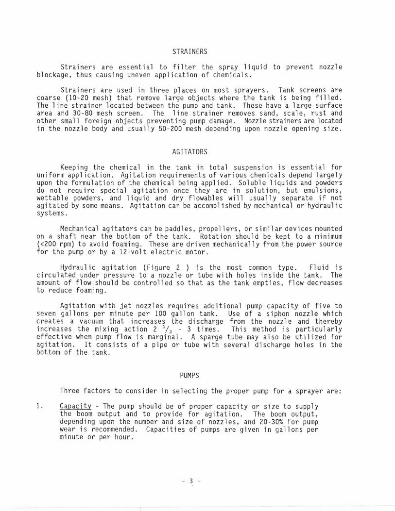
STRAINERS
Strainers are essential to filter the spray liquid to prevent nozzle blockage, thus causing uneven application of chemicals.
Strainers are used in three places on most sprayers. Tank screens are coarse (10-20 mesh) that remove large objects where the tank is being filled. The line strainer located between the pump and tank. These have a large surface area and 30-80 mesh screen. The line strainer removes sand, scale, rust and other small foreign objects preventing pump damage. Nozzle strainers are located in the nozzle body and usually 50-200 mesh depending upon nozzle opening size.
AGITATORS
Keeping the chemical in the tank in total suspension is essential for uniform application. Agitation requirements of various chemicals depend largely upon the formulation of the chemical being applied. Soluble liquids and powders do not require special agitation once they are in solution, but emulsions, wettable powders, and liquid and dry flowables will usually separate if not agitated by some means. Agitation can be accompl ished by mechanical or hydraulic systems.
Mechanical agitators can be paddles, propellers, or similar devices mounted on a shaft near the bottom of the tank. Rotation should be kept to a minimum «200 rpm) to avoid foaming. These are driven mechanically from the power source for the pump or by a 12-volt electric motor.
Hydraulic agitation (Figure 2 ) is the most common type. Fluid is circulated under pressure to a nozzle or tube with holes inside the tank. The amount of flow should be controlled so that as the tank empties, flow decreases to reduce foaming.
Agitation with jet nozzles requires additional pump capacity of five to seven gallons per minute per 100 gallon tank. Use of a siphon nozzle which creates a vacuum that increases the discharge from the nozzl e and thereby increases the mixing action 2 l/Z - 3 times. This method is particularly effective when pump flow is marginal. A sparge tube may also be utilized for agitation. It consists of a pipe or tube with several discharge holes in the bottom of the tank.
PUMPS
Three factors to consider in selecting the proper pump for a sprayer are:
1. Capacity - The pump should be of proper capacity or size to supply the boom output and to provide for agitation. The boom output, depending upon the number and size of nozzles, and 20-30% for pump wear is recommended. Capacities of pumps are given in gallons per minute or per hour.
- 3

Sizing the Pump
The size of pump needed depends on (1) rate of application, (2) travel speed, (3) tank size and (4) sprayer width.
Pumps are rated in gallons per minute (GPM) which can be calculated with this formula:
MPH x Width (ft) x GPAGPM = 500
It is a good idea to allow additional capacity to compensate for tank agitation and pump wear. You can by changing above formula to this:
MPH x width (ft) x GPAGPM + .02 x tank size (gal) x 1.2 500
For example: To spray 20 GPA at 3 mph with a 16-ft (two rows 8 feet apart) boom you should have a pump rated at about 10 GPM.
3 x 16 x 20GPM = + (.02 X 300) X 1.2 9.5500
The formula adds 2.0 GPM per 100 gallon of tank capacity for agitation (with heavy wettable powders increase this to 0.05 or 5 GPM/I00 gal.) The 1.2 factor adds 20% for pump wear.
2. Pressure - The pump must produce the desired operating pressure for the spraying job to be done. Pressures are indicated as pounds per square inch (psi).
3. Resistance to corrosion and wear - The pump must be able to handle the chemical spray materials without excessive corrosion or wear. Care should be used in selecting a pump if wettable powders are to be used. Table 2 lists the various pumps and their advantages and disadvantages.
PRESSURE REGULATORS
Flow of spray liquid from the pump to nozzles is controlled by a pressure regulated valve (PRV) (Figure 3). This consists of spring-loaded diaphragm or ball valve which can be set at a particular pressure. When this pressure is exceeded, the valve opens and the excess liquid allowed into a by-pass line returning to the spray tank. Liquid returned to the spray tank in this way provide partial hydraulic agitation of the spray liquid. A separate flow line to the agitator in addition to the by-pass line from the pressure regulating valve is necessary on all sprayers. When the pressure gauge is mounted next to the valve, readings have to be checked against pressures measured at the nozzles, so that account is taken of any drop in pressure between the valve and the nozzles.
- 4

TIlBLE 2. SUHHARY OF HIE VARIOUS TYPES OF PUHPS USED FOR SPRAYING
Cnl1RACTERISTIC PISTON GEAR ROLLER IHPELLfR DIAPIIRAGH I1HtRHAL GEAR CEHTRIFlJGIlL
Adaptability: Handle Wide range of Oil elulsion, non Works best with oil Will handle all Will not handle Will handle coarse & corrosive or abrasive application. Will abrasive laterials. elulsions and non chelicals which abrasives. abrasive laterials. lIaterials handle corrosive and Cannot be used with abrasive laterial. will not attack
abrasive laterials wettable powders. Recoillend not using diaphragl. copper cOlpounds. Rubber rollers for slurries &wettable powders.
Durability Basic parts have long Lilited life under Pressure drops with Haintains pressure Cannot operate dry. Pressure drops with life. adverse conditions. wear. with wear. Pressure drops wear.
rapidly with wear.
Serviceabi li ty Readily serviced. Parts not usually Special technique in Readily disasselbled Parts readily Certain lodels can replaced. PUlP servicing. Worn for service. changed. be serviced. readily replaced. parts can be
replaced.U1
Construction Cylinders-ceralic, Bronze gears, Rollers-nylon or Rubber or synthetic Hickel cast iron and Case: Cast iron or (er i tical par ts) stainless steel, stainless steel rubber. Case diaphragl. stainless steel plastic. Ilpellers:
bronze. shaft. nickel, cast iron. shaft. Cast iron, bronze and plastic.
Pressure Range 0--1000 psi 0--100 psi 0--150 psi 0--150 psi 0--120 psi 0--50 psi
RPH (Operating Range) ~OO to 1000 500 to 1800 300 to 1000 500 to 800 500 to 600 1200 to 3500
Gallons per .inute 3--10 0--65 5--50 }--10 0--100 0--100
Rgguired horsepower 2 to 6 HP 1/6 to ~ liP 1/2 to 5JIP 3 to 5 HP 1/6 to 4HP 11~ to 3 HP
Displace.r.nt Posi ti ve Seli-posi ti ve Seli-posi ti ve Posi tive Seli -posi ti ve Han-positive
Direction of rotation Clockwise Either Clockwise Either Clockwise Clockwise
BEARINGS:
Type Bronze or ball Bronze Bronze or ball Ball Bronze Ball sealed
Lubrication Grease Grease Sealed or grease Grease Grease or grease
T~ drive _ 1J0~ beltLJlLcl!ain_ _ PTO, belt, or chain PTO, belt, or chain PTO PTO, belt, or chain PTO, belt, or chain

Re turn to Tank
From Pump To Nozzles
Figure 3. Pressure Regulator
..... .....
;;,:;.;~g&~~~~ FLAT FAN
SOLID CONE
:::: .~ .' ;''',
:.;j:.Ji~ EVEN FAN
.:-.: .
~:>.~ ,;.,/' HOLLOW CONE
Side View
FLOOD TYPE
Figure 4. Examples of spray nozzles used on christmas trees.
- 6

CONTROL VALVE
Between the pressure regulating valve and the nozzles, an ON/OFF valve is positioned so that it can be easily operated by the tractor driver. Often there is a simple mechanical lever for the driver to operate, but for the totally enclosed safety cabs, electrically operated solenoid valves are required for remote control and to avoid pipes containing pesticides being in the cab. When the spray boom is divided into three sections, left, right, and central, the main valve is often a seven-way valve, so that individual sections, pairs or the whole boom can be operated. This is particularly useful when the edges of fields are being treated and part of the boom is not required.
CONDUITS
Pipes and/or hoses are used to carry spray material from the tank to the nozzles. These conduits must be capable of withstanding pressures created by the system pump. Hoses should have a burst pressure well above the normal working pressure of the hose. Hoses are available with one ply, two ply and wire reinforced construction. The wire reinforced hoses should be used where very high operating pressures are anticipated (over 200 psi). As hose size (diameter) increases, the working pressure decreases.
Suction hoses should be at least as large as the inlet port on the pump. The suction hose should be wire reinforced to prevent collapse of the hose. Collapsed hoses restrict flow to the pump and accelerate pump wear.
Hose size on the pressure side of the pump depends on the flow rate, hose 1ength, and operat i ng pressure. Sma11 hoses may restri ct flow and create unnecessarily high pressures. This results in accelerated pump wear and increased possibility of ruptured hoses.
Table 3. Suggested Hose Sizes for Boom Sprayers
Pump (GPM) out put Suction Hose Pressure Hose up to 12 3/4" 5/8" 12 25 1 " 3/4"26 - 50 1 - 1/4" 1 " 51 - 100 1 - 1/2" 1 - 1/4"
Hoses should be constructed of material that is resistant to the chemical action of spray material used. Two common materials used for sprayer hoses are EVA (ethylene vinyl acetate) and EPDM (ethylene propylene diane monomer).
Remember that restrictions in the hose will affect pressure and output. Quick connect couplings and fittings with inside diameters smaller than the inside diameter of the hose will restrict flow.
- 7
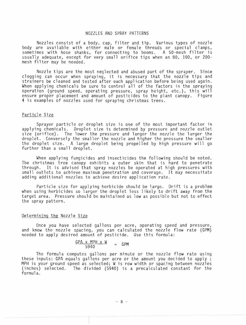
NOZZLES AND SPRAY PATTERNS
Nozzles consist of a body, cap, filter and tip. Various types of nozzle body are available with either male or female threads or special clamps, sometimes with hose shanks, for connecting to booms. A 50-mesh filter is usually adequate, except for very small orifice tips when an 80, 100, or 200mesh filter may be needed.
Nozzle tips are the most neglected and abused part of the sprayer. Since clogging can occur when spraying, it is necessary that the nozzle tips and strainers be cleaned and tested after each application before being used again. When applying chemicals be sure to control all of the factors in the spraying operation (ground speed, operating pressure, spray height, etc.), this will ensure proper placement and amount of pesticides to the plant canopy. Figure 4 is examples of nozzles used for spraying christmas trees.
Particle Size
Sprayer particle or droplet size is one of the most important factor in applying chemicals. Droplet size is determined by pressure and nozzle outlet size (orifice). The lower the pressure and larger the nozzle the larger the droplet. Conversely the smaller the nozzle and higher the pressure the smaller the droplet size. A large droplet being propelled by high pressure will go further than a small droplet.
When applying fungicides and insecticides the following should be noted. The chri stmas tree canopy exh i bits a outer ski n that is hard to penetrate through. It is advised that spray nozzles be operated at high pressures with small outlets to achieve maximum penetration and coverage. It may necessitate adding additional nozzles to achieve desire application rate.
Particle size for applying herbicide should be large. Drift is a problem when using herbicides so larger the droplet less likely to drift away from the target area. Pressure should be maintained as low as possible but not to effect the spray pattern.
Determining the Nozzle Size
Once you have selected gallons per acre, operating speed and pressure, and know the nozzl e spac i ng, you can cal cul ated the nozzl e fl ow rate (GPM) needed to apply desired amount of pesticide. Use this formula:
GPA x MPH x W GPM5940
The formula computes gallons per minute or the nozzle flow rate using these inputs: GPA equals gallons per acre or the amount you decided to apply; MPH is your ground speed as selected; Wis row width or spacing between nozzles (inches) selected. The divided (5940) is a precalculated constant for the formula.
- 8

Example: Assume SO-degree flat-fan nozzles spaced on 20-inch centers, a 20-GPA application rate and operating speed of 3 MPH. Substituting these values in the formula you get:
20 GPA x 3 MPH x 20 inch = GPM5940
GPM = 0.2 gallons per minute per nozzle.
Once nozzle flow rate has been figured, you then select the nozzle with comparab1e fl ow rate when operated at the pressure you selected. For our example calculation we would look for a nozzle with a GPM figure close to 0.2 at an operating pressure around 25 or 30 psi. With extra heavy or thick sprays you will have to compensate for the viscosity.
Herbicide Application
A flat fan type nozzle should be used for applying broadcast herbicides. Flat fan nozzles produce an elliptical pattern, where the edges are light and heavy in the center. These should be spaced on the boom for 30 - 40 percent overlap. When it becomes necessary to band apply herbicides use a even fan or flood nozzle. These nozzles produce an uniform pattern across the area sprayed. The fan nozzles should be operated at 20 - 40 psi. Flood nozzles are designed to operate at lower pressures 5 - 15 psi. The capacity of both type nozzles should be 15 - 20 gpa when operated at 21
/ 2 - 4 miles per hour.
Insecticide, Fungicide and Foliar Colorant
When applying insecticides, fungicides and foliar colorant solid or hollow cone type nozzl es shoul d be used. These two patterns can be produced by different tip configurations. One type tip disc-n-core consists of two parts. One being a core (swirl plate) where the fluid enters and is force through tangential openings. Then a disc-type harden stainless steel orifice (opening) is added. Another type tip that produces the same patterns is of one piece construction (nozzle body). Liquid is passes through a precision distributor with diagonal slots which produce swirl in a converging chamber. The resulting pattern of both tip configurations is either solid or hollow cone. Under normal conditions, nozzle tips should be approximately 6 - 10 inches from the foliage. They should have the capacity to apply 20 - 50 gallons per acre operating at 60 - 400 psi depending on the density of the foliage and age of trees. Generally, ground speed should be 21
/ 2 - 4 miles per hour.
Boom Configuration
Figure 5 illustrates one method for setup for applying insecticides, fungicides or foliar sprays to trees via hydraulic sprayer. The sprayers should be a maximum of 42 -48 inches at its widest point. This will allow operation between rows of trees without damage to them. The boom should be constructed so that a clearance height of 7 - S feet can be obtained. Also, boom height adjustment should made easily from the operators position. In production of Christmas trees, growers will have several different age plantings. Therefore, the ability to adjust boom height during application would be time saving.
- 9
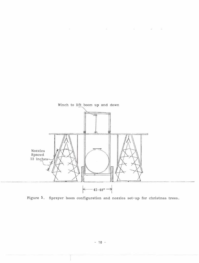
Winch to lift boom up and down
Nozzles Spaced 12 inches
Iii ________. -.f::===~'__._ L,__~ ..
Figure 5. Sprayer boom configuration and nozzles set-up for christmas trees.
- 10
f-42-4811 -1

This setup can be modified easily to apply herbicides. Place blanks in the nozzles along the slanted boom. Then add one or two nozzles at the end of the slanted boom for drop nozzle herbicide application.
Sprayers should be calibrated often. Calibration should be conducted every eight to 10 hours of operation to ensure proper pesticide application. A good calibration procedure to follow is "Calibration Method for Hydraulic Boom and Band sprayers and other Liquid Applicators" circular 683. Contact your County Extension Agent.
APPLICATION EQUIPMENT MAINTENANCE
All equipment must be checked thoroughly before the beginning of each season and on rout i ne bas is duri ng the season to keep equ i pment in good mechanical condition. Give special attention to valves, nozzles, tubing, connections, and other components that may leak. Replace parts promptly when they show signs of wear or malfunction.
Equipment Care
For the safety of the applicator and efficiency of application, the equipment needs to be calibrated accurately to dispense the pesticide in the prescribed amounts. The label must be strictly followed. An overdosage could be a prime cause of illegal residues, as well as a potential source of human i nj ury.
An agitator should be the right size to insure efficient mixture of the chemical. The agitator must be checked periodically to make sure it is operating correctly.
All washers and gaskets should be checked before each seasonal use, and on a routine basis during the operating season to prevent leakage.
Hose Care
A worker w"ill not use his mouth to siphon or blowout nozzles and clogged lines on any pesticide equipment. A siphon bulb, pump or other type mechanical device should be used for these repairs.
Sprayer hoses are subjected to high pressure and they present a definite hazard to the operator should the hose burst. Through proper maintenance and storage this hazard can be minimized.
The following safety checks and precautions are recommended:
1. Hoses should be inspected under high pressure by using plain water before each seasonal use and periodically during the use season.
2. Store hoses when not in use, this should be in a dark area to prevent U.V. breakdown of the rubber.
- 11
3. Do not hang hose over a nail or other sharp objects, as this can cause a weak-spot- in the hose.
4. Hoses can be wrapped around a metal drum or other suitable objects to prevent creasing.
Cleaning Sprayers
Herbicide residue in a tank loaded with insecticide could seriously damage susceptible plants; also, insecticide residue in a herbicide tank could result in high toxicity to humans if the chemicals are incompatible.
The suggested cleaning procedures are as follows:
1. Thoroughly flush the tank with warm water and a detergent. Then fill it with a solution of one part household ammonia in 100 parts of water. Run some of the solution through the sprayer boom and nozzles. Allow the solution to remain in the equipment for 12 to 24 hours, then remove it and rinse the equipment with water.
2. Rinse the tank for about 2 minutes with a 0.25 percent suspension of activated charcoal (1/4 pound of activated charcoal in 10 gallons of water) to which has been added a small quantity of household detergent. Run some of the suspension through the boom and nozzles. Empty the tank and rinse with clean water.
3. Neither of the above methods is always completely effective. To test the equipment for herbicide residue fill the tank with water and spray seedlings of a sensitive plant such as bean, tomato, or a sensitive weed. If the plant is not affected within 2 days, the equipment is safe for further use.
Cleaning According to Types of Formulations:
1. Wettable Powders - rinse the tank with water containing a wetting agent or detergent; then rinse with plain water.
2. Emulsions - Flush the tank with large quantities of water, with agitator running. Rinse once or twice with an oil solvent (paint thinner or herbicidal naphtha). Flush again with water and drain.
3. Solutions - Rinse with the same kind of solvent used in the formulation previously contained in the tank; if this was an organic solvent, you may use paint thinner, herbicidal naphtha, or fuel oil. Drain the tank and rinse with soapy water. Rinse again with plain water.
- 12

THIS PUBLICATION WAS PREPARED WITH FUNDS MADE AVAILABLE FROM OIL OVER
_CI:iABGE~COURT SETTLEME.NT$ At::JP WITHIN THE GUIDELINES OF THE U.S. DEPARTMENT OF ENERGY. HOWEVER, ANY OPINIONS, FINDINGS, CONCLUSIONS, OR RECOMMENDATIONS
--ri-~-,-..,rI--- ' - •. ,- ~ -
EXPRESSED HEREIN ARE THOSE OF THE AUTHORS AND DO NOT NECESSARILY REFLECT
THE VIEW OF DOE.
Paur E. Sumner, Extension Engineer
The Cooperative Extension Service, The University of Georgia College of Agriculture offers educational programs, assistance and materials to all 'people without regard to
race, color, national origin, age, sex or handicap status. AN EQl)AL OPPORTUNITY EMPLOYER
Sept. 1989