Embed Size (px)
Citation preview
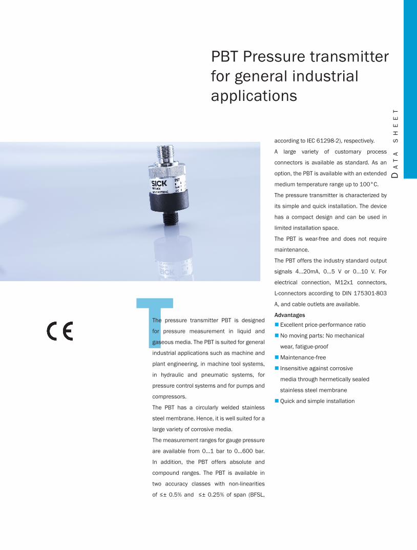
TThe pressure transmitter PBT is designed
for pressure measurement in liquid and
gaseous media. The PBT is suited for general
industrial applications such as machine and
plant engineering, in machine tool systems,
in hydraulic and pneumatic systems, for
pressure control systems and for pumps and
compressors.
The PBT has a circularly welded stainless
steel membrane. Hence, it is well suited for a
large variety of corrosive media.
The measurement ranges for gauge pressure
are available from 0…1 bar to 0…600 bar.
In addition, the PBT offers absolute and
compound ranges. The PBT is available in
two accuracy classes with non-linearities
of ≤± 0.5% and ≤± 0.25% of span (BFSL,
according to IEC 61298-2), respectively.
A large variety of customary process
connectors is available as standard. As an
option, the PBT is available with an extended
medium temperature range up to 100°C.
The pressure transmitter is characterized by
its simple and quick installation. The device
has a compact design and can be used in
limited installation space.
The PBT is wear-free and does not require
maintenance.
The PBT offers the industry standard output
signals 4…20mA, 0...5 V or 0…10 V. For
electrical connection, M12x1 connectors,
L-connectors according to DIN 175301-803
A, and cable outlets are available.
AdvantagesExcellent price-performance ratio �
No moving parts: No mechanical �
wear, fatigue-proof
Maintenance-free �
Insensitive against corrosive �
media through hermetically sealed
stainless steel membrane
Quick and simple installation �
PBT Pressure transmitter for general industrial applications
Da
ta
sh
ee
t
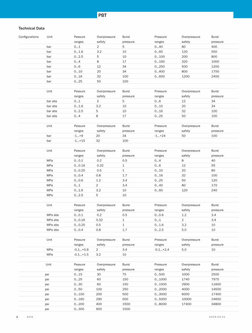
Technical Data
Configurations Unit Pessure Overpressure Burst Pressure Overpressure Burst ranges safety pressure ranges safety pressure bar 0…1 2 5 0…40 80 400 bar 0…1.6 3.2 10 0…60 120 550 bar 0…2.5 5 10 0…100 200 800 bar 0…4 8 17 0…160 320 1000 bar 0…6 12 34 0…250 500 1200 bar 0…10 20 34 0…400 800 1700 bar 0…16 32 100 0…600 1200 2400 bar 0…25 50 100
Unit Pessure Overpressure Burst Pressure Overpressure Burst ranges safety pressure ranges safety pressure bar abs 0…1 2 5 0…6 12 34 bar abs 0…1.6 3.2 10 0…10 20 34 bar abs 0…2.5 5 10 0…16 32 100 bar abs 0…4 8 17 0…25 50 100
Unit Pessure Overpressure Burst Pressure Overpressure Burst ranges safety pressure ranges safety pressure bar -1…+9 20 34 -1…+24 50 100 bar -1…+15 32 100
Unit Pessure Overpressure Burst Pressure Overpressure Burst ranges safety pressure ranges safety pressure MPa 0…0.1 0.2 0.5 0…4 8 40 MPa 0…0.16 0.32 1 0…6 12 55 MPa 0…0.25 0.5 1 0…10 20 80 MPa 0…0.4 0.8 1.7 0…16 32 100 MPa 0…0.6 1.2 3.4 0…25 50 120 MPa 0…1 2 3.4 0…40 80 170 MPa 0…1.6 3.2 10 0…60 120 240 MPa 0…2.5 5 10
Unit Pessure Overpressure Burst Pressure Overpressure Burst ranges safety pressure ranges safety pressure MPa abs 0…0.1 0.2 0.5 0…0.6 1.2 3.4 MPa abs 0…0.16 0.32 1 0…1 2 3.4 MPa abs 0…0.25 0.5 1 0…1.6 3.2 10 MPa abs 0…0.4 0.8 1.7 0…2.5 5.0 10
Unit Pessure Overpressure Burst Pressure Overpressure Burst ranges safety pressure ranges safety pressure MPa -0.1…+0.9 2 3.4 -0.1…+2.4 5.0 10 MPa -0.1…+1.5 3.2 10 Unit Pessure Overpressure Burst Pressure Overpressure Burst ranges safety pressure ranges safety pressure psi 0…15 30 75 0…500 1000 2500 psi 0…25 60 150 0…1000 1740 7975 psi 0…30 60 150 0…1500 2900 11600 psi 0…50 100 250 0…2000 4000 14500 psi 0…100 200 500 0…3000 6000 17400 psi 0…160 290 500 0…5000 10000 24650 psi 0…200 400 1500 0…8000 17400 34800 psi 0…300 600 1500
PBT
2 0 0 9 - 0 4 - 0 1 S I C K 32 S I C K 2 0 0 9 - 0 4 - 0 1 2 0 0 9 - 0 4 - 0 1 S I C K 3
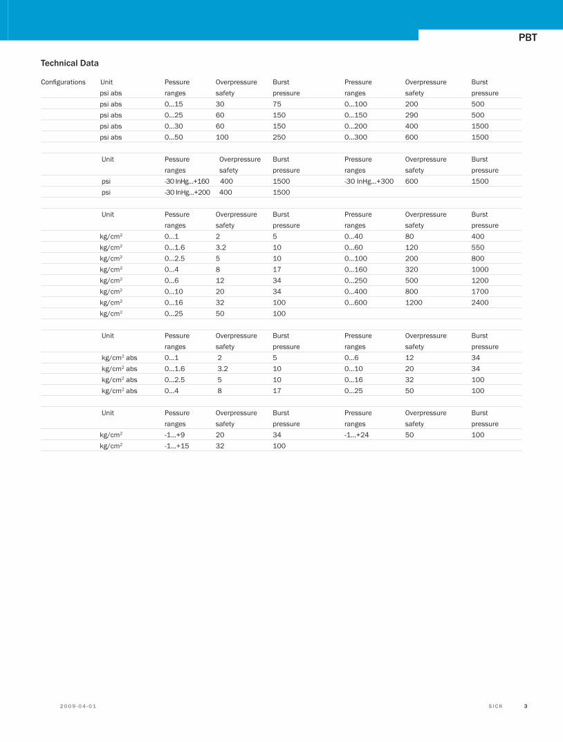
Technical Data
Configurations Unit Pessure Overpressure Burst Pressure Overpressure Burst psi abs ranges safety pressure ranges safety pressure psi abs 0…15 30 75 0…100 200 500 psi abs 0…25 60 150 0…150 290 500 psi abs 0…30 60 150 0…200 400 1500 psi abs 0…50 100 250 0…300 600 1500
Unit Pessure Overpressure Burst Pressure Overpressure Burst ranges safety pressure ranges safety pressure psi -30 InHg…+160 400 1500 -30 InHg…+300 600 1500 psi -30 InHg…+200 400 1500 Unit Pessure Overpressure Burst Pressure Overpressure Burst ranges safety pressure ranges safety pressure kg/cm2 0…1 2 5 0…40 80 400 kg/cm2 0…1.6 3.2 10 0…60 120 550 kg/cm2 0…2.5 5 10 0…100 200 800 kg/cm2 0…4 8 17 0…160 320 1000 kg/cm2 0…6 12 34 0…250 500 1200 kg/cm2 0…10 20 34 0…400 800 1700 kg/cm2 0…16 32 100 0…600 1200 2400 kg/cm2 0…25 50 100
Unit Pessure Overpressure Burst Pressure Overpressure Burst ranges safety pressure ranges safety pressure kg/cm2 abs 0…1 2 5 0…6 12 34 kg/cm2 abs 0…1.6 3.2 10 0…10 20 34 kg/cm2 abs 0…2.5 5 10 0…16 32 100 kg/cm2 abs 0…4 8 17 0…25 50 100
Unit Pessure Overpressure Burst Pressure Overpressure Burst ranges safety pressure ranges safety pressure kg/cm2 -1…+9 20 34 -1…+24 50 100 kg/cm2 -1…+15 32 100
PBT
2 0 0 9 - 0 4 - 0 1 S I C K 32 S I C K 2 0 0 9 - 0 4 - 0 1 2 0 0 9 - 0 4 - 0 1 S I C K 3
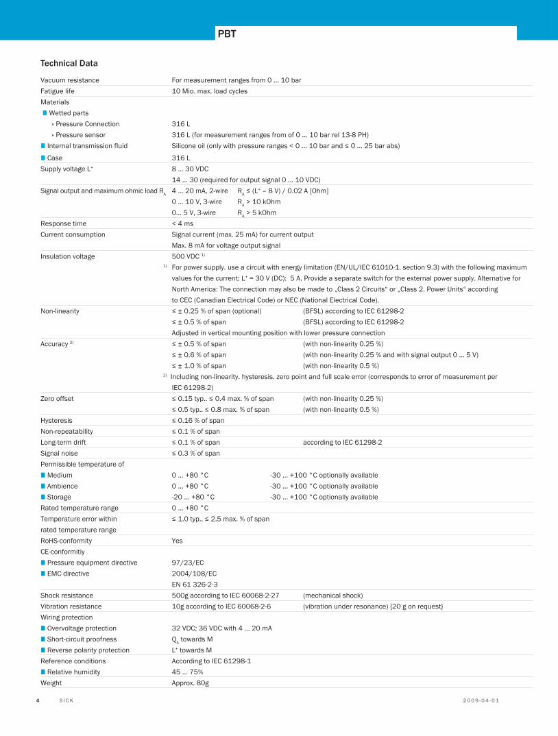
Technical Data Vacuum resistance For measurement ranges from 0 ... 10 bar Fatigue life 10 Mio. max. load cycles Materials ■ Wetted parts » Pressure Connection 316 L » Pressure sensor 316 L (for measurement ranges from of 0 ... 10 bar rel 13-8 PH) ■ Internal transmission fluid Silicone oil (only with pressure ranges < 0 ... 10 bar and ≤ 0 ... 25 bar abs)
■ Case 316 L Supply voltage L+ 8 ... 30 VDC 14 ... 30 (required for output signal 0 ... 10 VDC) Signal output and maximum ohmic load RA 4 ... 20 mA, 2-wire RA ≤ (L+ – 8 V) / 0.02 A [Ohm] 0 ... 10 V, 3-wire RA > 10 kOhm 0... 5 V, 3-wire RA > 5 kOhmResponse time < 4 ms Current consumption Signal current (max. 25 mA) for current output Max. 8 mA for voltage output signal Insulation voltage 500 VDC 1) 1) For power supply. use a circuit with energy limitation (EN/UL/IEC 61010-1. section 9.3) with the following maximum values for the current: L+ = 30 V (DC): 5 A. Provide a separate switch for the external power supply. Alternative for North America: The connection may also be made to „Class 2 Circuits“ or „Class 2. Power Units“ according to CEC (Canadian Electrical Code) or NEC (National Electrical Code). Non-linearity ≤ ± 0.25 % of span (optional) (BFSL) according to IEC 61298-2 ≤ ± 0.5 % of span (BFSL) according to IEC 61298-2 Adjusted in vertical mounting position with lower pressure connection Accuracy 2) ≤ ± 0.5 % of span (with non-linearity 0.25 %) ≤ ± 0.6 % of span (with non-linearity 0.25 % and with signal output 0 ... 5 V) ≤ ± 1.0 % of span (with non-linearity 0.5 %) 2) Including non-linearity. hysteresis. zero point and full scale error (corresponds to error of measurement per IEC 61298-2) Zero offset ≤ 0.15 typ.. ≤ 0.4 max. % of span (with non-linearity 0.25 %) ≤ 0.5 typ.. ≤ 0.8 max. % of span (with non-linearity 0.5 %) Hysteresis ≤ 0.16 % of span Non-repeatability ≤ 0.1 % of span Long-term drift ≤ 0.1 % of span according to IEC 61298-2 Signal noise ≤ 0.3 % of span Permissible temperature of ■ Medium 0 ... +80 °C -30 ... +100 °C optionally available ■ Ambience 0 ... +80 °C -30 ... +100 °C optionally available ■ Storage -20 ... +80 °C -30 ... +100 °C optionally availableRated temperature range 0 ... +80 °C Temperature error within ≤ 1.0 typ.. ≤ 2.5 max. % of span rated temperature range RoHS-conformity Yes CE-conformitiy ■ Pressure equipment directive 97/23/EC ■ EMC directive 2004/108/EC EN 61 326-2-3 Shock resistance 500g according to IEC 60068-2-27 (mechanical shock) Vibration resistance 10g according to IEC 60068-2-6 (vibration under resonance) {20 g on request} Wiring protection ■ Overvoltage protection 32 VDC; 36 VDC with 4 ... 20 mA ■ Short-circuit proofness QA towards M ■ Reverse polarity protection L+ towards M Reference conditions According to IEC 61298-1 ■ Relative humidity 45 ... 75% Weight Approx. 80g
PBT
2 0 0 9 - 0 4 - 0 1 S I C K 54 S I C K 2 0 0 9 - 0 4 - 0 1 2 0 0 9 - 0 4 - 0 1 S I C K 5
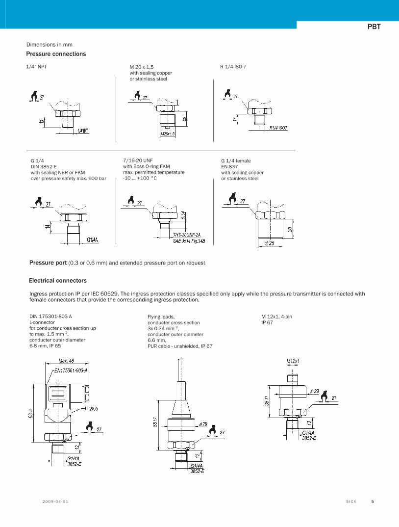
Dimensions in mm
Pressure connections
M 20 x 1,5with sealing copper or stainless steel
7/16-20 UNFwith Boss O-ring FKMmax. permitted temperature-10 ... +100 °C
1/4“ NPT
G 1/4DIN 3852-Ewith sealing NBR or FKMover pressure safety max. 600 bar
G 1/4 femaleEN 837with sealing copper or stainless steel
Pressure port (0.3 or 0.6 mm) and extended pressure port on request
R 1/4 ISO 7
DIN 175301-803 AL-connectorfor conducter cross section up to max. 1.5 mm 2, conducter outer diameter6-8 mm, IP 65
M 12x1, 4-pinIP 67
Flying leads,conducter cross section 3x 0.34 mm 2, conducter outer diameter6.6 mm,PUR cable - unshielded, IP 67
Ingress protection IP per IEC 60529. The ingress protection classes specified only apply while the pressure transmitter is connected with female connectors that provide the corresponding ingress protection.
Electrical connectors
PBT
2 0 0 9 - 0 4 - 0 1 S I C K 54 S I C K 2 0 0 9 - 0 4 - 0 1 2 0 0 9 - 0 4 - 0 1 S I C K 5
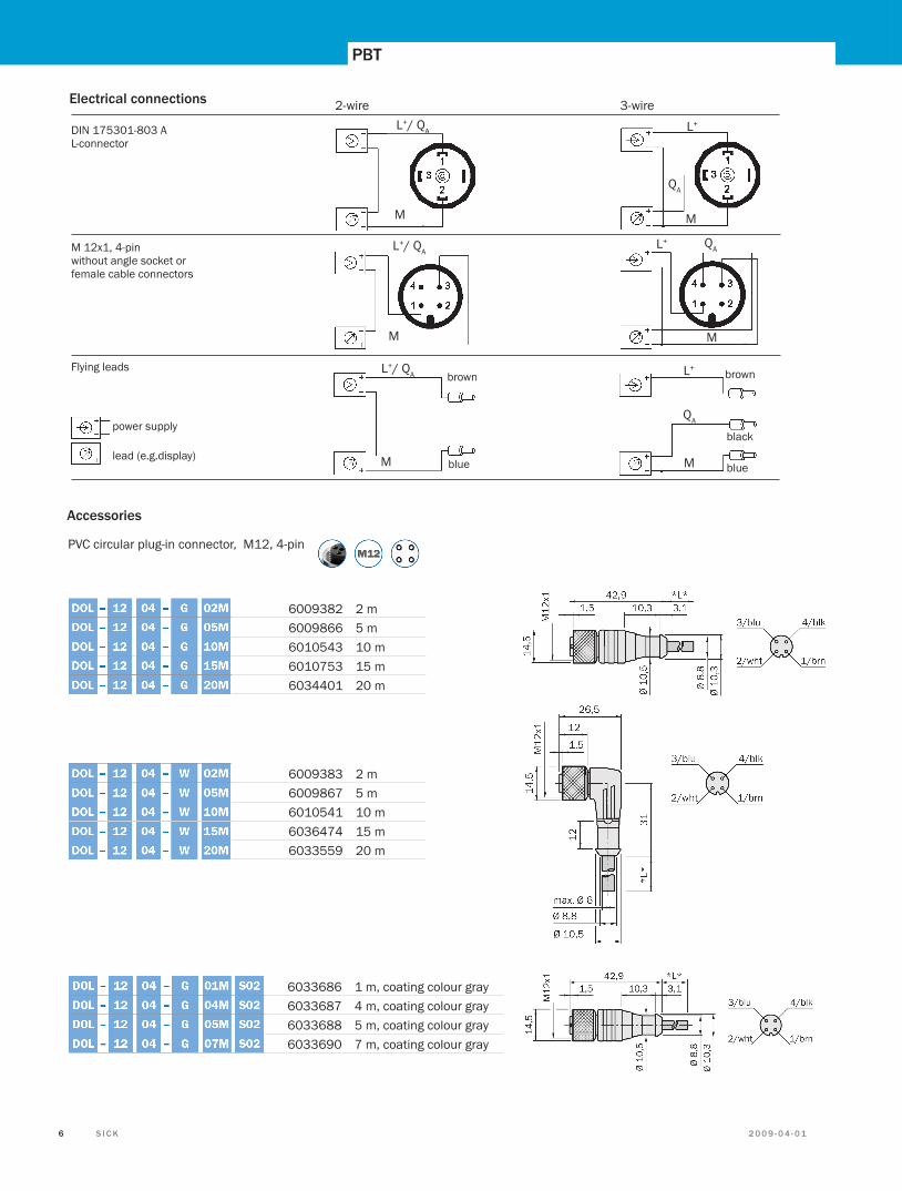
power supply
lead (e.g.display)
DIN 175301-803 AL-connector
brown
blue
brown
blue
black
3-wire2-wire
M 12x1, 4-pinwithout angle socket or female cable connectors
Flying leads
Electrical connections
QA
M
L+/ QA
M
L+/ QA
L+/ QA
M M
QA
L+
QA L+
M
M
L+
Accessories
PVC circular plug-in connector, M12, 4-pin
6009382 2 m 6009866 5 m 6010543 10 m 6010753 15 m 6034401 20 m
6009383 2 m 6009867 5 m 6010541 10 m 6036474 15 m 6033559 20 m
6033686 1 m, coating colour gray 6033687 4 m, coating colour gray 6033688 5 m, coating colour gray 6033690 7 m, coating colour gray
PBT
2 0 0 9 - 0 4 - 0 1 S I C K 76 S I C K 2 0 0 9 - 0 4 - 0 1 2 0 0 9 - 0 4 - 0 1 S I C K 7
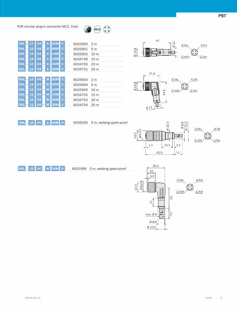
PUR circular plug-in connector M12, 4-pin
6025900 2 m 6025901 5 m 6025902 10 m 6034749 15 m 6034750 20 m 6034751 25 m
6025903 2 m 6025904 5 m 6025905 10 m 6034752 15 m 6034753 20 m 6034754 25 m
6026250 5 m, welding spark-proof
6020399 5 m, welding spark-proof
PBT
2 0 0 9 - 0 4 - 0 1 S I C K 76 S I C K 2 0 0 9 - 0 4 - 0 1 2 0 0 9 - 0 4 - 0 1 S I C K 7
PBT
2 0 0 9 - 0 4 - 0 1 S I C K 98 S I C K 2 0 0 9 - 0 4 - 0 1 2 0 0 9 - 0 4 - 0 1 S I C K 9
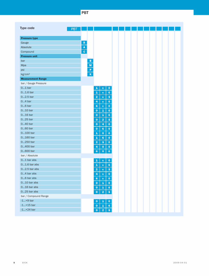
Pressure type
Gauge
Absolute
Compound
Pressure unit
bar
Mpa
psi
kg/cm²
Measurement Range
bar / Gauge Pressure
0...1 bar
0...1.6 bar
0...2.5 bar
0...4 bar
0...6 bar
0...10 bar
0...16 bar
0...25 bar
0...40 bar
0...60 bar
0...100 bar
0...160 bar
0...250 bar
0...400 bar
0...600 bar
bar / Absolute
0...1 bar abs
0...1.6 bar abs
0...2.5 bar abs
0...4 bar abs
0...6 bar abs
0...10 bar abs
0...16 bar abs
0...25 bar abs
bar / Compound Range
-1...+9 bar
-1...+15 bar
-1...+24 bar
Type code
PBT
2 0 0 9 - 0 4 - 0 1 S I C K 98 S I C K 2 0 0 9 - 0 4 - 0 1 2 0 0 9 - 0 4 - 0 1 S I C K 9
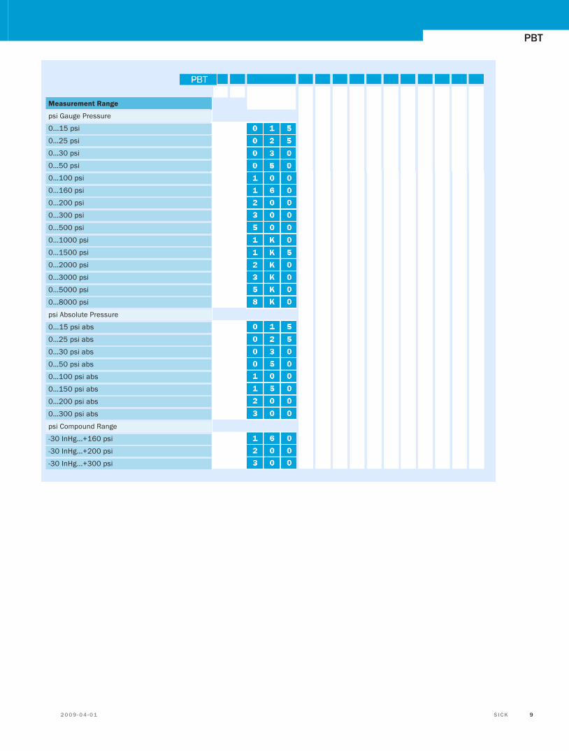
Measurement Range
psi Gauge Pressure
0...15 psi
0…25 psi
0…30 psi
0…50 psi
0…100 psi
0…160 psi
0…200 psi
0…300 psi
0…500 psi
0…1000 psi
0…1500 psi
0…2000 psi
0…3000 psi
0…5000 psi
0…8000 psi
psi Absolute Pressure
0...15 psi abs
0…25 psi abs
0…30 psi abs
0…50 psi abs
0…100 psi abs
0…150 psi abs
0…200 psi abs
0…300 psi abs
psi Compound Range
-30 InHg...+160 psi
-30 InHg...+200 psi
-30 InHg...+300 psi
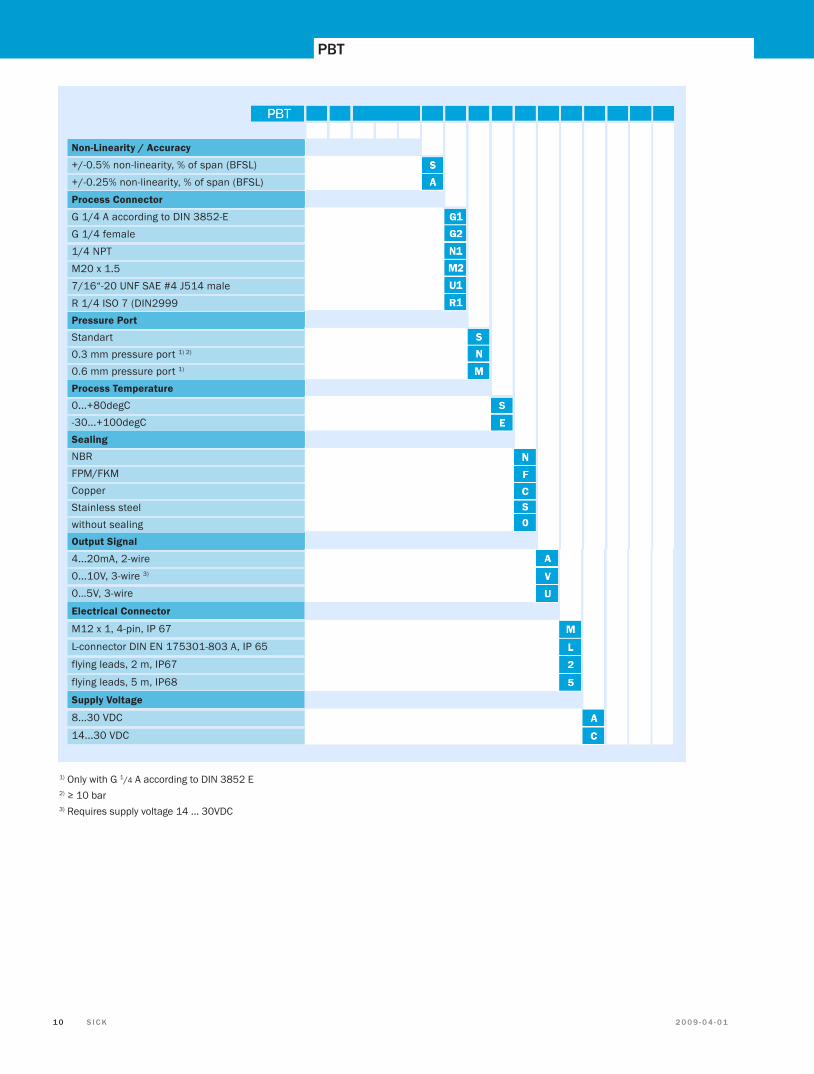
1) Only with G 1/4 A according to DIN 3852 E2) ≥ 10 bar3) Requires supply voltage 14 ... 30VDC
PBT
2 0 0 9 - 0 4 - 0 1 S I C K 1 11 0 S I C K 2 0 0 9 - 0 4 - 0 1 2 0 0 9 - 0 4 - 0 1 S I C K 1 1
Non-Linearity / Accuracy
+/-0.5% non-linearity, % of span (BFSL) +/-0.25% non-linearity, % of span (BFSL)Process Connector
G 1/4 A according to DIN 3852-E G 1/4 female 1/4 NPT M20 x 1.5 7/16“-20 UNF SAE #4 J514 male R 1/4 ISO 7 (DIN2999 Pressure Port
Standart 0.3 mm pressure port 1) 2) 0.6 mm pressure port 1) Process Temperature
0...+80degC -30...+100degC Sealing
NBR FPM/FKM Copper Stainless steel without sealing Output Signal
4...20mA, 2-wire 0...10V, 3-wire 3) 0…5V, 3-wire
Electrical Connector
M12 x 1, 4-pin, IP 67
L-connector DIN EN 175301-803 A, IP 65
flying leads, 2 m, IP67
flying leads, 5 m, IP68
Supply Voltage
8...30 VDC
14...30 VDC

PBT
2 0 0 9 - 0 4 - 0 1 S I C K 1 11 0 S I C K 2 0 0 9 - 0 4 - 0 1 2 0 0 9 - 0 4 - 0 1 S I C K 1 1
Notes
AustraliaPhone +61 3 9497 4100 1800 33 48 02 – tollfreeE-Mail [email protected]
Belgium/LuxembourgPhone +32 (0)2 466 55 66E-Mail [email protected]
BrasilPhone +55 11 3215-4900E-Mail [email protected]
Ceská RepublikaPhone +420 2 57 91 18 50E-Mail [email protected]
ChinaPhone +852-2763 6966E-Mail [email protected]
DanmarkPhone +45 45 82 64 00E-Mail [email protected]
DeutschlandPhone +49 211 5301-250E-Mail [email protected]
EspañaPhone +34 93 480 31 00E-Mail [email protected]
FrancePhone +33 1 64 62 35 00E-Mail [email protected]
Great BritainPhone +44 (0)1727 831121E-Mail [email protected]
IndiaPhone +91–22–4033 8333E-Mail [email protected]
IsraelPhone +972-4-999-0590E-Mail [email protected]
ItaliaPhone +39 02 27 43 41E-Mail [email protected]
JapanPhone +81 (0)3 3358 1341E-Mail [email protected]
NederlandsPhone +31 (0)30 229 25 44E-Mail [email protected]
Norge Phone +47 67 81 50 00E-Mail [email protected]
ÖsterreichPhone +43 (0)22 36 62 28 8-0E-Mail [email protected]
PolskaPhone +48 22 837 40 50E-Mail [email protected]
Republic of KoreaPhone +82-2 786 6321/4E-Mail [email protected]
Republika SlowenijaPhone +386 (0)1-47 69 990E-Mail [email protected]
RomâniaPhone +40 356 171 120 E-Mail [email protected]
RussiaPhone +7 495 775 05 34E-Mail [email protected]
SchweizPhone +41 41 619 29 39E-Mail [email protected]
SingaporePhone +65 6744 3732E-Mail [email protected]
SuomiPhone +358-9-25 15 800E-Mail [email protected]
SverigePhone +46 10 110 10 00E-Mail [email protected]
TaiwanPhone +886 2 2375-6288E-Mail [email protected]
TürkiyePhone +90 216 587 74 00E-Mail [email protected]
USA/Canada/MéxicoPhone +1(952) 941-6780 1 800-325-7425 – tollfreeE-Mail [email protected]
More representatives and agencies in all major industrial nations at www.sick.com
SICK AG | Waldkirch | Germany | www.sick.com
8013
160/
2009
-04-
01 /
FD ∙
Prin
ted
in G
erm
any
(200
9-04
) ∙ S
ubje
ct to
cha
nge
with
out n
otic
e ∙ T
he s
peci
fied
prod
uct f
eatu
res
and
tech
nica
l dat
a do
not
repr
esen
t any
gua
rant
ee ∙
01 U
S m
odie
fied
4c in
t32


![] ØU æ¼ ¬ - sick.tta.ru | главная страницаsick.tta.ru/sites/sick.tta.ru/files/File/pdf/DIV02/S3000...Operating Instructions S3000 6 © SICK AG • Industrial Safety](https://img.pdfslide.net/doc/110x75/5abcf55c7f8b9a24028e71a0/-u-sickttaru-sickttarusitessickttarufilesfilepdfdiv02s3000operating.jpg)