Embed Size (px)
DESCRIPTION
CarbonandStainlessSteel Gate,GlobeandCheckValves CarbonandStainlessSteel Gate,GlobeandCheckValves ® ®
Citation preview
Cast Steel DSI®
Carbon and Stainless SteelGate, Globe and Check Valves
Cast SteelDSI®
Carbon and Stainless SteelGate, Globe and Check Valves
Contents
Cast Steel Standard Features 3
Testing, Modifications and Accessories 4
Standard Product Range 4With DSI® Zy-Gear Bevel Gear Chart
NACE Conformance 5And General Design Specifications
Specifying DSI® Carbon Steel Figure Numbers 6Specifying DSI® Stainless Steel Figure Numbers 7
Gate Valves 8-13
Globe Valves 14-17
Swing Check Valves 18-21
Pressure Temperature Ratings 22
Warranty And Returns Policy 23
Z Y - T E C H G L O B A L I N D U S T R I E S
API, ASTM, ASME, ANSI and otherrecognized standards. DSI® Cast
Steel Valves are not only character-ized by outstanding performance,reliability and quality, they’re alsoknown for their standard featuresnormally optional in otherbrands. All flanged DSI® Cast
Steel Valves come standard with125-250 RA flange finishes.
DSI® utilizes flexible graphite pack-ing, a variety of gasket materials
and exacting assembly & testingprocedures to ensure compliance
with the World’s emissions controlstandards. Visit our website to find
out more about Zy-Tech GlobalIndustries and other DSI®
quality products.
For years, DSI® Cast Steel Valves have beensatisfying the needs of Petroleum Refineries,Chemical Processing Plants, PowerGenerating Plants, and other processing
facilities throughout the world.Our Cast Steel Valves are
designed, engineered andmanufactured in strict
conformance to
Contents
Cast Steel Standard Features 3
Testing, Modifications and Accessories 4
Standard Product Range 4With DSI® Zy-Gear Bevel Gear Chart
NACE Conformance 5And General Design Specifications
Specifying DSI® Carbon Steel Figure Numbers 6Specifying DSI® Stainless Steel Figure Numbers 7
Gate Valves 8-13
Globe Valves 14-17
Swing Check Valves 18-21
Pressure Temperature Ratings 22
Warranty And Returns Policy 23
Standard Features of DSI® Cast Steel Valves
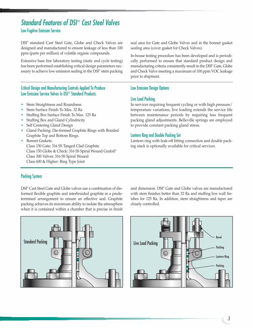
Packing System
DSI® Cast Steel Gate and Globe valves use a combination of die-formed flexible graphite and interbraided graphite in a prede-termined arrangement to ensure an effective seal. Graphitepacking achieves its maximum ability to isolate the atmospherewhen it is contained within a chamber that is precise in finish
Low Fugitive Emission Service
DSI® standard Cast Steel Gate, Globe and Check Valves aredesigned and manufactured to ensure leakage of less than 100ppm (parts per million) of volatile organic compounds.
Extensive base line laboratory testing (static and cycle testing)has been performed establishing critical design parameters nec-essary to achieve low emission sealing in the DSI® stem packing
Critical Design and Manufacturing Controls Applied To ProduceLow Emission Service Valves In DSI® Standard Products.
• Stem Straightness and Roundness• Stem Surface Finish To Max. 32 Ra• Stuffing Box Surface Finish To Max. 125 Ra• Stuffing Box and Gland Cylindricity• Self Centering Gland Design• Gland Packing: Die-formed Graphite Rings with Braided
Graphite Top and Bottom Rings.• Bonnet Gaskets:
Class 150 Gate: 316 SS Tanged Clad GraphiteClass 150 Globe & Check: 316 SS Spiral Wound Grafoil®
Class 300 Valves: 316 SS Spiral Wound Class 600 & Higher: Ring Type Joint
Low Emission Design Options
Live Load Packing In services requiring frequent cycling or with high pressure/temperature variations, live loading extends the service lifebetween maintenance periods by requiring less frequentpacking gland adjustments. Belleville springs are employedto provide constant packing gland stress.
Lantern Ring and Double Packing SetLantern ring with leak-off fitting connection and double pack-ing stack is optionally available for critical services.
Packing
Lantern Ring
Packing
Bevel
Standard Packing Live Load Packing
and dimension. DSI® Gate and Globe valves are manufacturedwith stem finishes better than 32 Ra and stuffing box wall fin-ishes for 125 Ra. In addition, stem straightness and taper areclosely controlled.
seal area for Gate and Globe Valves and in the bonnet gasketsealing area (cover gasket for Check Valves).
In-house testing procedure has been developed and is periodi-cally performed to ensure that standard product design andmanufacturing criteria consistently result in the DSI® Gate, Globeand Check Valve meeting a maximum of 100 ppm VOC leakageprior to shipment.
3
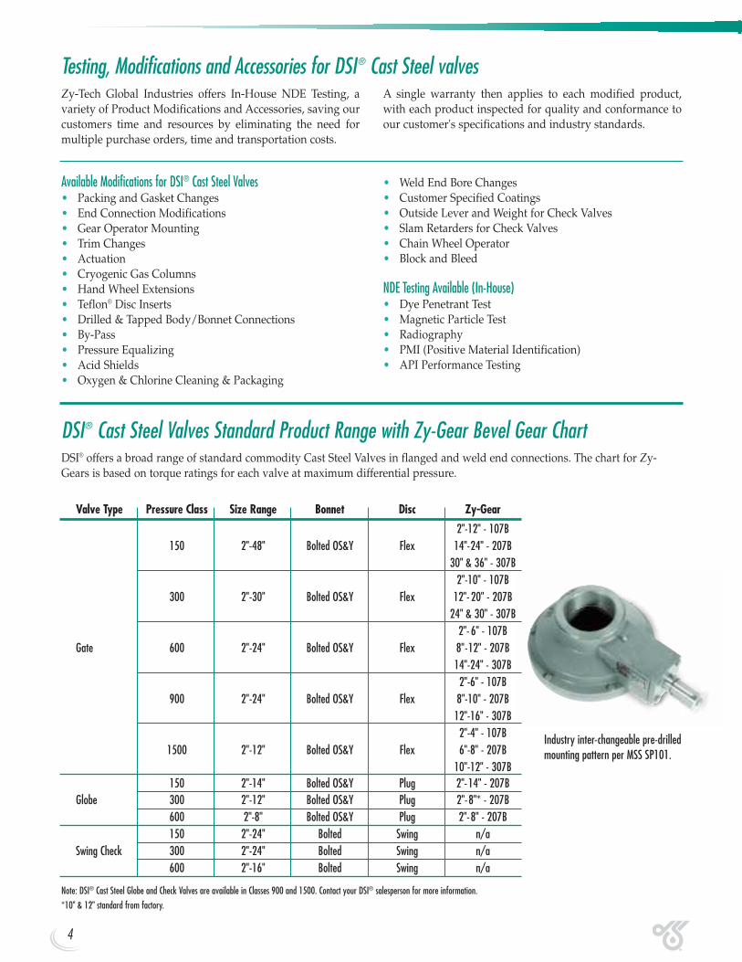
Industry inter-changeable pre-drilledmounting pattern per MSS SP101.
Testing, Modifications and Accessories for DSI® Cast Steel valvesZy-Tech Global Industries offers In-House NDE Testing, avariety of Product Modifications and Accessories, saving ourcustomers time and resources by eliminating the need formultiple purchase orders, time and transportation costs.
A single warranty then applies to each modified product,with each product inspected for quality and conformance toour customer's specifications and industry standards.
Available Modifications for DSI® Cast Steel Valves• Packing and Gasket Changes• End Connection Modifications• Gear Operator Mounting• Trim Changes• Actuation• Cryogenic Gas Columns• Hand Wheel Extensions• Teflon® Disc Inserts• Drilled & Tapped Body/Bonnet Connections • By-Pass• Pressure Equalizing• Acid Shields• Oxygen & Chlorine Cleaning & Packaging
• Weld End Bore Changes• Customer Specified Coatings• Outside Lever and Weight for Check Valves• Slam Retarders for Check Valves• Chain Wheel Operator• Block and Bleed
NDE Testing Available (In-House) • Dye Penetrant Test• Magnetic Particle Test• Radiography• PMI (Positive Material Identification)• API Performance Testing
Valve Type Pressure Class Size Range Bonnet Disc Zy-Gear
2"-12" - 107B 150 2"-48" Bolted OS&Y Flex 14"-24" - 207B
30" & 36" - 307B2"-10" - 107B
300 2"-30" Bolted OS&Y Flex 12"- 20" - 207B24" & 30" - 307B
2"- 6" - 107BGate 600 2"-24" Bolted OS&Y Flex 8"-12" - 207B
14"-24" - 307B2"-6" - 107B
900 2"-24" Bolted OS&Y Flex 8"-10" - 207B12"-16" - 307B
2"-4" - 107B1500 2"-12" Bolted OS&Y Flex 6"-8" - 207B
10"-12" - 307B150 2"-14" Bolted OS&Y Plug 2"-14" - 207B
Globe 300 2"-12" Bolted OS&Y Plug 2"-8"* - 207B600 2"-8" Bolted OS&Y Plug 2"-8" - 207B150 2"-24" Bolted Swing n/a
Swing Check 300 2"-24" Bolted Swing n/a600 2"-16" Bolted Swing n/a
Note: DSI® Cast Steel Globe and Check Valves are available in Classes 900 and 1500. Contact your DSI® salesperson for more information.
*10" & 12" standard from factory.
DSI® Cast Steel Valves Standard Product Range with Zy-Gear Bevel Gear ChartDSI® offers a broad range of standard commodity Cast Steel Valves in flanged and weld end connections. The chart for Zy-Gears is based on torque ratings for each valve at maximum differential pressure.
4

LUF-N LUF-N-LCC XUF-NValve Parts Carbon Steel LowTempCarbon Steel Carbon Steel NotesBody, Bonnet ASTM A216 WCB ASTM A352 LCC ASTM A216 WCB Maximum hardness 22Rc/235HB
4"& under ASTM A182 F316 4" & under ASTM A105/Disc + Disc Faces 6" & above ASTM A216 ASTM A352 LCC/316 Stellite® 6, 6" & above
Heat affected zone and weld deposit hardnesses
WCB/316 ASTM A216 WCB/Stellite® 6 are controlled to 22 Rc/235HB maximum
Stem, Backseat ASTM A182 F316 ASTM A182 F316ASTM A276 T410, All from solid bar or forging, no welding,ASTM A182 F6A maximum hardness 22Rc/235HB
Gland ASTM A182 F6A ASTM A182 F316 ASTM A182 F6A Same as above
ASTM A105 plus ASTM A352 LF2 plus Base material and heat affected zone hardnesses
Seat + Seat FacesStellite® 6 weld deposit Stellite® 6 weld deposit
ASTM A105/Stellite® 6 are controlled to 22Rc/235HB maximum, Stellite® 6facing to NACE MR0175 Sec. 4 and Sec. 5
Bonnet Bolts ASTM A193 B7M ASTM A320 L7M ASTM A193 B7MMaterials are suitable for direct exposure
to H2S, NACE MR0175 Sec. 6
Bonnet Nuts ASTM A194 2HM ASTM A194 7M ASTM A194 2HM Same as above
Note: Other trims available in NACE.
NACE Compliant Material Specifications for Gate Valves
ConformanceNACE MR0175 Compliant
Over recent years the demand for valves resistant to sulfidestress cracking in facilities handling H2S bearing hydrocarbonshas increased dramatically. Varying concentrations of H2S,pressure, temperature and the medium itself, whether it befluid, gas or multi-phase, plus other factors all have a bearingon the appropriate metallic material selection.
DSI® offers three basic valves which have been proven reliableand which fully comply with the NACE MR0175 Latest Editionspecification. The typical material configurations of the NACEcompliant DSI® Carbon and Low Temperature Carbon SteelGate Valves are shown below.
Welding
Welding and weld repair operations are conducted in accor-dance with applicable ASTM material specifications and NACEMR0175 using procedures and personnel qualified to ASMESection IX.
Material Test Reports
Material test reports for DSI® Cast Steel valves are availableupon request. Material test reports meet the requirements ofEN 10204 3.1b
American Standard British Standard Item Description
BS1414 (Gate Valve)API 600 BS1873 (Globe Valve) Shell wall thickness and general valve design specifications
BS1868 (Check Valve)
ANSI B16.34 BS1560 Pressure temperature ratingsANSI B16.10 BS2080 Face-to-face dimensions, End-to-end dimensionsANSI B16.5* BS1560 End flange dimensions, Gasket contact facing
BS1414 (Gate Valve)ANSI B16.25 BS1873 (Globe Valve) Welding end dimensions
BS1868 (Check Valve)
*Valves 26” and larger according to ANSI B16.47 Series A (MSS SP-44) and Series B (API 605).
General Design SpecificationsDSI® Cast Steel Valves are manufactured in strict accordance with the following standards:
5
DSI® Cast Steel Valves meet all essential safety requirements of the Pressures Equipment Directive 97/23/EC and may be freely marketed in the European Economic Area.DSI® products may be used in applications requiring up to category II product.
6
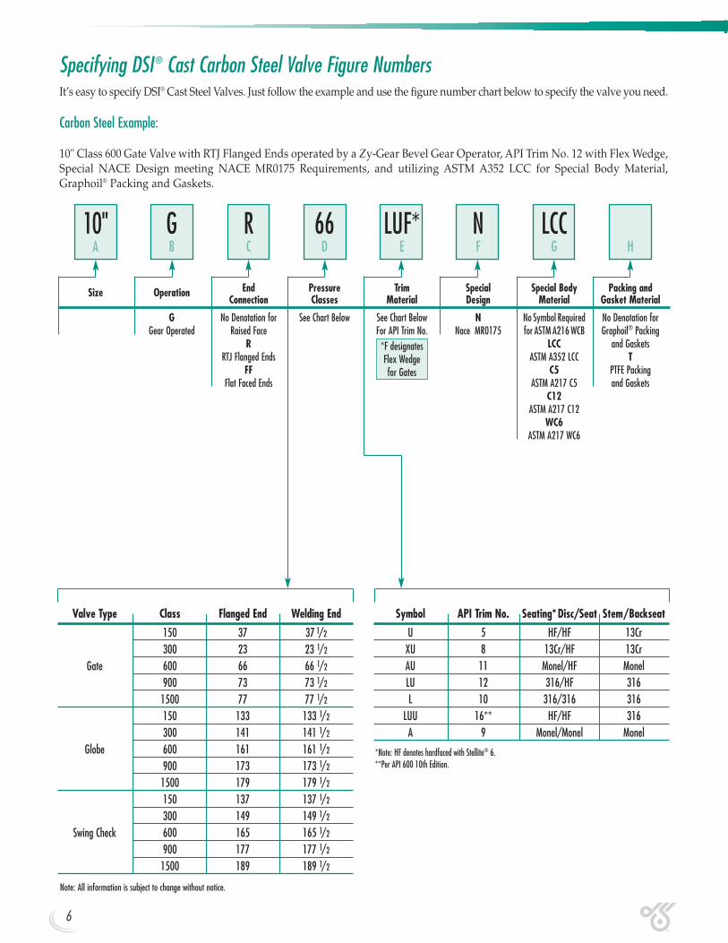
Specifying DSI® Cast Carbon Steel Valve Figure NumbersIt’s easy to specify DSI® Cast Steel Valves. Just follow the example and use the figure number chart below to specify the valve you need.
Carbon Steel Example:
10" Class 600 Gate Valve with RTJ Flanged Ends operated by a Zy-Gear Bevel Gear Operator, API Trim No. 12 with Flex Wedge,Special NACE Design meeting NACE MR0175 Requirements, and utilizing ASTM A352 LCC for Special Body Material,Graphoil® Packing and Gaskets.
Valve Type Class Flanged End Welding End
150 37 37 1/2
300 23 23 1/2
Gate 600 66 66 1/2
900 73 73 1/2
1500 77 77 1/2
150 133 133 1/2
300 141 141 1/2
Globe 600 161 161 1/2
900 173 173 1/2
1500 179 179 1/2
150 137 137 1/2
300 149 149 1/2
Swing Check 600 165 165 1/2
900 177 177 1/2
1500 189 189 1/2
Symbol API Trim No. Seating*Disc/Seat Stem/Backseat
U 5 HF/HF 13CrXU 8 13Cr/HF 13CrAU 11 Monel/HF MonelLU 12 316/HF 316L 10 316/316 316
LUU 16** HF/HF 316A 9 Monel/Monel Monel
*Note: HF denotes hardfaced with Stellite® 6.**Per API 600 10th Edition.
Note: All information is subject to change without notice.
End Pressure Trim Special Special Body Packing andSize OperationConnection Classes Material Design Material Gasket Material
G No Denotation for See Chart Below See Chart Below N No Symbol Required No Denotation for Gear Operated Raised Face For API Trim No. Nace MR0175 for ASTM A216 WCB Graphoil® Packing
R *F designates LCC and GasketsRTJ Flanged Ends Flex Wedge ASTM A352 LCC T
FF for Gates C5 PTFE Packing Flat Faced Ends ASTM A217 C5 and Gaskets
C12ASTM A217 C12
WC6ASTM A217 WC6
10" G R 66 LUF* N LCCA B C D E F G H
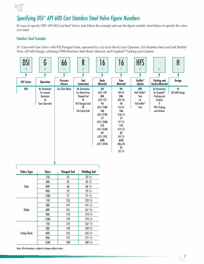
Specifying DSI® API 600 Cast Stainless Steel Valve Figure NumbersIt’s easy to specify DSI® API 600 Cast Steel Valves. Just follow the example and use the figure number chart below to specify the valveyou need.
Stainless Steel Example:
16" Class 600 Gate Valve with RTJ Flanged Ends, operated by a Zy-Gear Bevel Gear Operator, 316 Stainless Steel and half Stellite®
Trim, API 600 Design, utilizing CF8M Stainless Steel Body Material, and Graphoil® Packing and Gaskets.
Valve Type Class Flanged End Welding End
150 37 37 1/2
300 23 23 1/2
Gate 600 66 66 1/2
900 73 73 1/2
1500 77 77 1/2
150 133 133 1/2
300 141 141 1/2
Globe 600 161 161 1/2
900 173 173 1/2
1500 179 179 1/2
150 137 137 1/2
300 149 149 1/2
Swing Check 600 165 165 1/2
900 177 177 1/2
1500 189 189 1/2
Note: All information is subject to change without notice.
Pressure End Body Trim Stellite® Packing and DesignDSI Series OperationClasses Connection Material Material Option GasketMaterial
DSI No Denotation See Chart Below No Denotation 04 04 HFS No Denotation Hfor manual for Raised Face A351 CF8 304 SS Half Stellite® for Graphoil® API 600 Design Operation Flanged End 04L 04L Trim Packing and
G R A351 CF3 304 LSS U GasketsGear Operated RTJ Flanged Ends 16 16 Full Stellite® T
FF A351 CF8M 316 SS Trim PTFE PackingFlat Faced Ends 16L 16L and Gaskets
A351 CF3M 316L SS17 17
A351 CG8M 317 SS17L 17L
A351 CG3M 317L SS47 47
A351 CF8C 347 SSA20 A20
A351 CN7M Alloy 2021
321 SS
DSI G 66 R 16 16 HFS HA B C D E F G H I
7
8
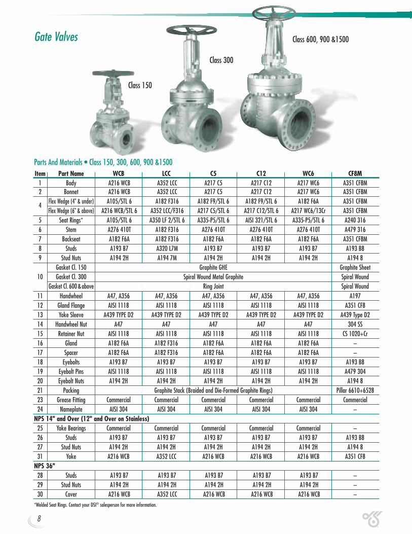
Gate Valves
Parts And Materials • Class 150, 300, 600, 900 &1500Item Part Name WCB LCC C5 C12 WC6 CF8M
1 Body A216 WCB A352 LCC A217 C5 A217 C12 A217 WC6 A351 CF8M2 Bonnet A216 WCB A352 LCC A217 C5 A217 C12 A217 WC6 A351 CF8M
4Flex Wedge (4" & under) A105/STL 6 A182 F316 A182 F9/STL 6 A182 F9/STL 6 A182 F6A A351 CF8MFlex Wedge (6" & above) A216 WCB/STL 6 A352 LCC/F316 A217 C5/STL 6 A217 C12/STL 6 A217 WC6/13Cr A351 CF8M
5 Seat Rings* A105/STL 6 A350 LF 2/STL 6 A335-P5/STL 6 AISI 321/STL 6 A335-P5/STL 6 A240 3166 Stem A276 410T A182 F316 A276 410T A276 410T A276 410T A479 3167 Backseat A182 F6A A182 F316 A182 F6A A182 F6A A182 F6A A351 CF8M8 Studs A193 B7 A320 L7M A193 B7 A193 B7 A193 B7 A193 B89 Stud Nuts A194 2H A194 7M A194 2H A194 2H A194 2H A194 8
Gasket Cl. 150 Graphite GHE Graphite Sheet10 Gasket Cl. 300 Spiral Wound Metal Graphite Spiral Wound
Gasket Cl. 600 &above Ring Joint Spiral Wound11 Handwheel A47, A356 A47, A356 A47, A356 A47, A356 A47, A356 A19712 Gland Flange AISI 1118 AISI 1118 AISI 1118 AISI 1118 AISI 1118 A351 CF813 Yoke Sleeve A439 TYPE D2 A439 TYPE D2 A439 TYPE D2 A439 TYPE D2 A439 TYPE D2 A439 Type D214 Handwheel Nut A47 A47 A47 A47 A47 304 SS15 Retainer Nut AISI 1118 AISI 1118 AISI 1118 AISI 1118 AISI 1118 CS 1020+Cr16 Gland A182 F6A A182 F316 A182 F6A A182 F6A A182 F6A –17 Spacer A182 F6A A182 F316 A182 F6A A182 F6A A182 F6A –18 Eyebolts A193 B7 A193 B7 A193 B7 A193 B7 A193 B7 A193 B819 Eyebolt Pins AISI 1118 AISI 1118 AISI 1118 AISI 1118 AISI 1118 A479 30420 Eyebolt Nuts A194 2H A194 2H A194 2H A194 2H A194 2H A194 821 Packing Graphite Stack (Braided and Die-Formed Graphite Rings) Pillar 6610+652823 Grease Fitting Commercial Commercial Commercial Commercial Commercial Commercial24 Nameplate AISI 304 AISI 304 AISI 304 AISI 304 AISI 304 –
NPS 14" and Over (12" and Over on Stainless)25 Yoke Bearings Commercial Commercial Commercial Commercial Commercial –26 Studs A193 B7 A193 B7 A193 B7 A193 B7 A193 B7 A193 B827 Stud Nuts A194 2H A194 2H A194 2H A194 2H A194 2H A194 831 Yoke A216 WCB A352 LCC A216 WCB A216 WCB A216 WCB A351 CF8
NPS 36"28 Studs A193 B7 A193 B7 A193 B7 A193 B7 A193 B7 –29 Stud Nuts A194 2H A194 2H A194 2H A194 2H A194 2H –30 Cover A216 WCB A352 LCC A216 WCB A216 WCB A216 WCB –
*Welded Seat Rings. Contact your DSI® salesperson for more information.
Class 600, 900 &1500
Class 300
Class 150

H
D1D2
D3D
Dk
L L1fa
n x d
11
14
13
18
1921
6
24
20
10
8
1
4
5
15
23
12
16
2
9
7
17
NPS 14" And Over2 Piece Yoke
31
26
27
17
NPS 36"Ball Bearing Yoke Sleeve
30
28
29
NPS 14"-30"Ball Bearing Yoke Sleeve
25H1OPEN
Class 150 Gate Valves(37-37 1/2)
End Flange
Bolt HoleSize D D1 D2 n d D3 a f L L1 H H1(open) Dk Wt. Lbs. Cv
2 2.00 6.00 4.75 4 0.75 3.62 0.63 0.06 7.00 8.50 12.80 15.63 7.87 45 298.72 1/2 2.50 7.00 5.50 4 0.75 4.13 0.71 0.06 7.50 9.50 15.94 19.48 9.84 57 466.7
3 3.00 7.50 6.00 4 0.75 5.00 0.75 0.06 8.00 11.12 16.93 20.55 9.84 66 694.14 4.00 9.00 7.50 8 0.75 6.18 0.94 0.06 9.00 12.00 19.09 23.70 9.84 103 12346 6.00 11.00 9.50 8 0.87 8.50 1.02 0.06 10.50 15.88 25.91 32.60 11.81 163 2873.98 8.00 13.50 11.75 8 0.87 10.63 1.14 0.06 11.50 16.50 30.94 39.69 15.75 273 5109.1
10 10.00 16.00 14.25 12 0.98 12.75 1.22 0.06 13.00 18.00 37.68 48.62 17.72 532 8622.612 12.00 19.00 17.00 12 0.98 15.00 1.26 0.06 14.00 19.75 43.70 56.70 19.69 558 12416.514 13.25 21.00 18.75 12 1.12 16.25 1.38 0.06 15.00 22.50 47.80 62.09 19.69 860 17651.716 15.25 23.50 21.25 16 1.12 18.50 1.46 0.06 16.00 24.00 54.61 71.15 22.05 1235 23055.318 17.25 25.00 22.75 16 1.26 21.00 1.57 0.06 17.00 26.00 61.00 79.50 24.80 1455 30603.620 19.25 27.50 25.00 20 1.26 23.00 1.69 0.06 18.00 28.00 66.06 86.53 24.80 1742 37782.224 23.25 32.00 29.50 20 1.38 27.25 1.89 0.06 20.00 32.00 78.25 102.86 27.95 2557 57349.4
30(A) 29.00 38.75 36.00 28 1.38 33.75 2.95 0.06 24.00 36.00 93.70 124.01 31.50 4674 9504430(B) 29.00 34.94 33.31 44 0.87 32.00 1.77 0.06 24.00 36.00 93.70 124.01 31.50 4189 9504436(A) 34.50 46.00 42.75 32 1.61 40.25 3.58 0.06 28.00 40.00 117.68 154.93 35.43 7086 146313.136(B) 34.50 41.62 39.75 44 0.98 38.25 2.09 0.06 28.00 40.00 117.68 154.93 35.43 6272 146313.1
Dimensional Data (in.) and Flow Coefficient (Cv)
9
10
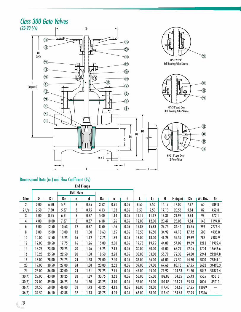
Class 300 Gate Valves(23-23 1/2)
NPS 12" And Over2 Piece Yoke
31
26
27
17
NPS 30" And OverBall Bearing Yoke Sleeve
30
28
29
NPS 12"-24"Ball Bearing Yoke Sleeve
25
17
11
14
21
18
10
24
4
6
1
20
5
15
23
19
7
16
13
2
8
9
12
H(approx.)
D1D2
D3D
Dk
L L1fa
n x d
H1OPEN
End Flange
Bolt HoleSize D D1 D2 n d D3 a f L L1 H H1(open) Dk Wt. Lbs. Cv
2 2.00 6.50 5.71 8 0.75 3.62 0.91 0.06 8.50 8.50 14.17 17.00 7.87 60 289.82 1/2 2.50 7.50 5.87 8 0.75 4.13 1.02 0.06 9.50 9.50 17.13 20.56 9.84 82 452.8
3 3.00 8.25 6.61 8 0.87 5.00 1.14 0.06 11.12 11.12 18.31 21.93 9.84 98 672.14 4.00 10.00 7.87 8 0.87 6.18 1.26 0.06 12.00 12.00 20.47 25.08 9.84 143 1194.86 6.00 12.50 10.63 12 0.87 8.50 1.46 0.06 15.88 15.88 27.75 34.44 15.75 296 2776.48 8.00 15.00 13.00 12 1.00 10.63 1.65 0.06 16.50 16.50 34.92 44.13 17.72 500 4935.8
10 10.00 17.50 15.25 16 1.12 12.75 1.89 0.06 18.00 18.00 41.26 52.52 19.69 787 7982.912 12.00 20.50 17.75 16 1.26 15.00 2.00 0.06 19.75 19.75 44.09 57.09 19.69 1213 11929.414 13.25 23.00 20.25 20 1.26 16.25 2.13 0.06 30.00 30.00 49.00 63.29 22.05 1704 15646.616 15.25 25.50 22.50 20 1.38 18.50 2.28 0.06 33.00 33.00 55.79 72.33 24.80 2244 21207.818 17.00 28.00 24.75 24 1.38 21.00 2.40 0.06 36.00 36.00 61.00 79.50 24.80 2800 26841.120 19.00 30.50 27.00 24 1.38 23.00 2.52 0.06 39.00 39.00 67.68 88.15 27.95 3682 34490.324 23.00 36.00 32.00 24 1.61 27.25 2.75 0.06 45.00 45.00 79.92 104.53 31.50 5842 51874.4
30(A) 29.00 43.00 39.25 28 1.89 33.75 3.62 0.06 55.00 55.00 102.83 134.25 35.43 9535 8501030(B) 29.00 39.00 36.25 36 1.50 33.25 3.70 0.06 55.00 55.00 102.83 134.25 35.43 9006 8501036(A) 34.50 50.00 46.00 32 1.73 40.25 4.13 0.06 68.00 68.00 117.40 154.65 37.25 13029 —36(B) 34.50 46.10 42.88 32 1.73 39.75 4.09 0.06 68.00 68.00 117.40 154.65 37.25 12346 —
Dimensional Data (in.) and Flow Coefficient (Cv)
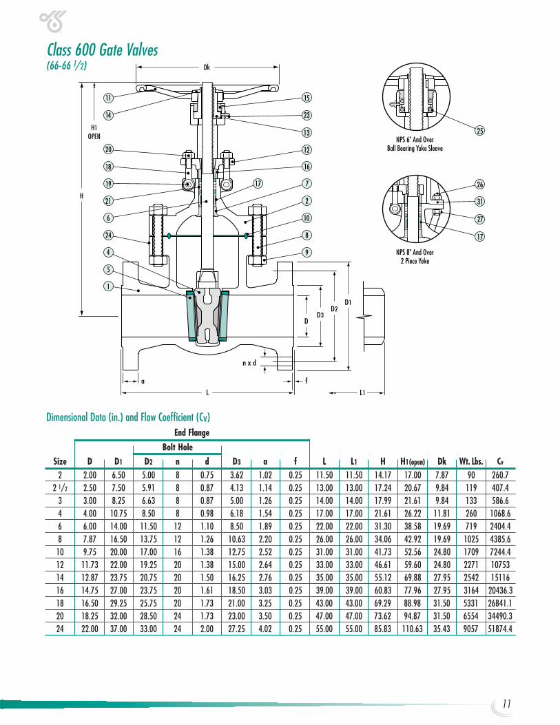
Class 600 Gate Valves(66-66 1/2)
NPS 8" And Over2 Piece Yoke
31
26
27
17
NPS 6" And OverBall Bearing Yoke Sleeve
25
H
D1D2
D3D
Dk
L L1
fa
n x d
17
11
14
19
18
6
24
4
21
1
20
5
15
23
7
16
12
13
2
10
8
9
H1OPEN
End Flange
Bolt HoleSize D D1 D2 n d D3 a f L L1 H H1(open) Dk Wt. Lbs. Cv
2 2.00 6.50 5.00 8 0.75 3.62 1.02 0.25 11.50 11.50 14.17 17.00 7.87 90 260.72 1/2 2.50 7.50 5.91 8 0.87 4.13 1.14 0.25 13.00 13.00 17.24 20.67 9.84 119 407.4
3 3.00 8.25 6.63 8 0.87 5.00 1.26 0.25 14.00 14.00 17.99 21.61 9.84 133 586.64 4.00 10.75 8.50 8 0.98 6.18 1.54 0.25 17.00 17.00 21.61 26.22 11.81 260 1068.66 6.00 14.00 11.50 12 1.10 8.50 1.89 0.25 22.00 22.00 31.30 38.58 19.69 719 2404.48 7.87 16.50 13.75 12 1.26 10.63 2.20 0.25 26.00 26.00 34.06 42.92 19.69 1025 4385.6
10 9.75 20.00 17.00 16 1.38 12.75 2.52 0.25 31.00 31.00 41.73 52.56 24.80 1709 7244.412 11.73 22.00 19.25 20 1.38 15.00 2.64 0.25 33.00 33.00 46.61 59.60 24.80 2271 1075314 12.87 23.75 20.75 20 1.50 16.25 2.76 0.25 35.00 35.00 55.12 69.88 27.95 2542 1511616 14.75 27.00 23.75 20 1.61 18.50 3.03 0.25 39.00 39.00 60.83 77.96 27.95 3164 20436.318 16.50 29.25 25.75 20 1.73 21.00 3.25 0.25 43.00 43.00 69.29 88.98 31.50 5331 26841.120 18.25 32.00 28.50 24 1.73 23.00 3.50 0.25 47.00 47.00 73.62 94.87 31.50 6554 34490.324 22.00 37.00 33.00 24 2.00 27.25 4.02 0.25 55.00 55.00 85.83 110.63 35.43 9057 51874.4
Dimensional Data (in.) and Flow Coefficient (Cv)
11
12
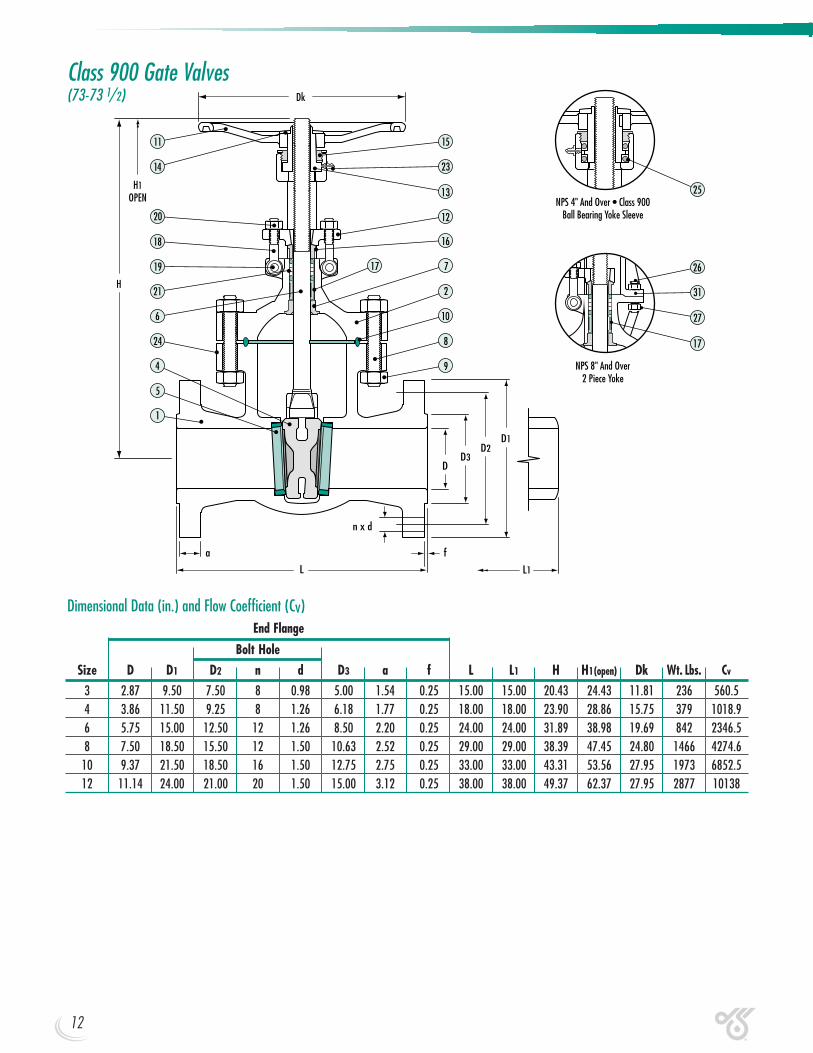
Class 900 Gate Valves(73-73 1/2)
NPS 8" And Over2 Piece Yoke
31
26
27
17
NPS 4" And Over • Class 900Ball Bearing Yoke Sleeve
25
H
D1D2
D3D
Dk
L L1
fa
n x d
H1OPEN
17
11
14
19
18
6
24
4
1
20
5
15
23
7
16
12
13
2
10
8
9
21
End Flange
Bolt HoleSize D D1 D2 n d D3 a f L L1 H H1(open) Dk Wt. Lbs. Cv
3 2.87 9.50 7.50 8 0.98 5.00 1.54 0.25 15.00 15.00 20.43 24.43 11.81 236 560.54 3.86 11.50 9.25 8 1.26 6.18 1.77 0.25 18.00 18.00 23.90 28.86 15.75 379 1018.96 5.75 15.00 12.50 12 1.26 8.50 2.20 0.25 24.00 24.00 31.89 38.98 19.69 842 2346.58 7.50 18.50 15.50 12 1.50 10.63 2.52 0.25 29.00 29.00 38.39 47.45 24.80 1466 4274.6
10 9.37 21.50 18.50 16 1.50 12.75 2.75 0.25 33.00 33.00 43.31 53.56 27.95 1973 6852.512 11.14 24.00 21.00 20 1.50 15.00 3.12 0.25 38.00 38.00 49.37 62.37 27.95 2877 10138
Dimensional Data (in.) and Flow Coefficient (Cv)
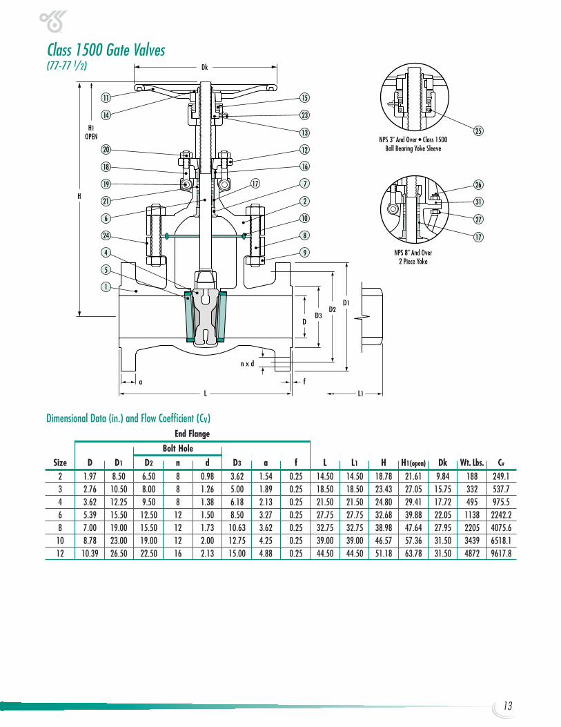
Class 1500 Gate Valves(77-77 1/2)
NPS 8" And Over2 Piece Yoke
31
26
27
17
NPS 3" And Over • Class 1500Ball Bearing Yoke Sleeve
25
H
D1D2
D3D
Dk
L L1
fa
n x d
11
14
19
18
6
24
4
21
1
20
5
15
23
717
16
12
13
2
10
8
9
H1OPEN
End Flange
Bolt HoleSize D D1 D2 n d D3 a f L L1 H H1(open) Dk Wt. Lbs. Cv
2 1.97 8.50 6.50 8 0.98 3.62 1.54 0.25 14.50 14.50 18.78 21.61 9.84 188 249.13 2.76 10.50 8.00 8 1.26 5.00 1.89 0.25 18.50 18.50 23.43 27.05 15.75 332 537.74 3.62 12.25 9.50 8 1.38 6.18 2.13 0.25 21.50 21.50 24.80 29.41 17.72 495 975.56 5.39 15.50 12.50 12 1.50 8.50 3.27 0.25 27.75 27.75 32.68 39.88 22.05 1138 2242.28 7.00 19.00 15.50 12 1.73 10.63 3.62 0.25 32.75 32.75 38.98 47.64 27.95 2205 4075.6
10 8.78 23.00 19.00 12 2.00 12.75 4.25 0.25 39.00 39.00 46.57 57.36 31.50 3439 6518.112 10.39 26.50 22.50 16 2.13 15.00 4.88 0.25 44.50 44.50 51.18 63.78 31.50 4872 9617.8
Dimensional Data (in.) and Flow Coefficient (Cv)
13
14
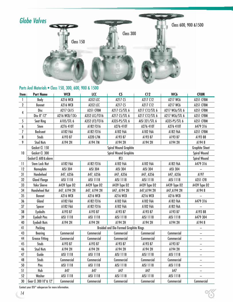
Globe Valves
Parts And Materials • Class 150, 300, 600, 900 & 1500Item Part Name WCB LCC C5 C12 WC6 CF8M
1 Body A216 WCB A352 LCC A217 C5 A217 C12 A217 WC6 A351 CF8M2 Bonnet A216 WCB A352 LCC A217 C5 A217 C12 A217 WC6 A351 CF8M
4Disc A217 CA15 A351 CF8M A217 C5/STL 6 A217 C12/STL 6 A217 WC6/STL 6 A351 CF8M
Disc 8"-12" A216 WCB/13Cr A352 LCC/F316 A217 C5/STL 6 A217 C12/STL 6 A217 WC6/STL 6 A351 CF8M5 Seat Ring A105/STL 6 A352 LF2/F316 A335-P5/STL 6 AISI 321/STL 6 A335-P5/STL 6 A351 CF8M6 Stem A276 410T A182 F316 A276 410T A276 410T A276 410T A479 3167 Backseat A182 F6A A182 F316 A182 F6A A182 F6A A182 F6A A351 CF8M8 Studs A193 B7 A320 L7M A193 B7 A193 B7 A193 B7 A193 B89 Stud Nuts A194 2H A194 7M A194 2H A194 2H A194 2H A194 8
Gasket Cl. 150 Spiral Wound Graphite Graphite Sheet10 Gasket Cl. 300 Spiral Wound Graphite Spiral Wound
Gasket Cl. 600 & above RTJ Spiral Wound11 Stem Lock Nut A182 F6A A182 F316 A182 F6A A182 F6A A182 F6A A479 31612 Nameplate AISI 304 AISI 304 AISI 304 AISI 304 AISI 304 –31 Handwheel A47, A356 A47, A356 A47, A356 A47, A356 A47, A356 A19732 Gland Flange AISI 1118 AISI 1118 AISI 1118 AISI 1118 AISI 1118 A351 CF833 Yoke Sleeve A439 Type D2 A439 Type D2 A439 Type D2 A439 Type D2 A439 Type D2 A439 Type D234 Handwheel Nut A47, A194 2H A47, A194 2H A47, A194 2H A47,A194 2H A47,A194 2H A194 835 Bonnet A216 WCB A216 WCB A216 WCB A216 WCB A216 WCB –36 Gland A182 F6A A182 F316 A182 F6A A182 F6A A182 F6A A479 31637 Spacer A182 F6A A182 F316 A182 F6A A182 F6A A182 F6A –38 Eyebolts A193 B7 A193 B7 A193 B7 A193 B7 A193 B7 A193 B839 Eyebolt Pins AISI 1118 AISI 1118 AISI 1118 AISI 1118 AISI 1118 A479 30440 Eyebolt Nuts A194 2H A194 2H A194 2H A194 2H A194 2H A194 841 Packing Braided and Die-Formed Graphite Rings –43 Bearing Commercial Commercial Commercial Commercial Commercial –44 Grease Fitting Commercial Commercial Commercial Commercial Commercial –45 Studs A193 B7 A193 B7 A193 B7 A193 B7 A193 B7 –46 Stud Nuts A194 2H A194 2H A194 2H A194 2H A194 2H –47 Guide AISI 1118 AISI 1118 AISI 1118 AISI 1118 AISI 1118 –48 Studs Commercial Commercial Commercial Commercial Commercial –50 Pins AISI 1118 AISI 1118 AISI 1118 AISI 1118 AISI 1118 –51 Hub A47 A47 A47 A47 A47 –52 Washer AISI 1118 AISI 1118 AISI 1118 AISI 1118 AISI 1118 –30 Gear Cl. 300 10" & 12" Commercial Commercial Commercial Commercial Commercial Commercial
Contact your DSI® salesperson for more information.
Class 600, 900 &1500
Class 300
Class 150
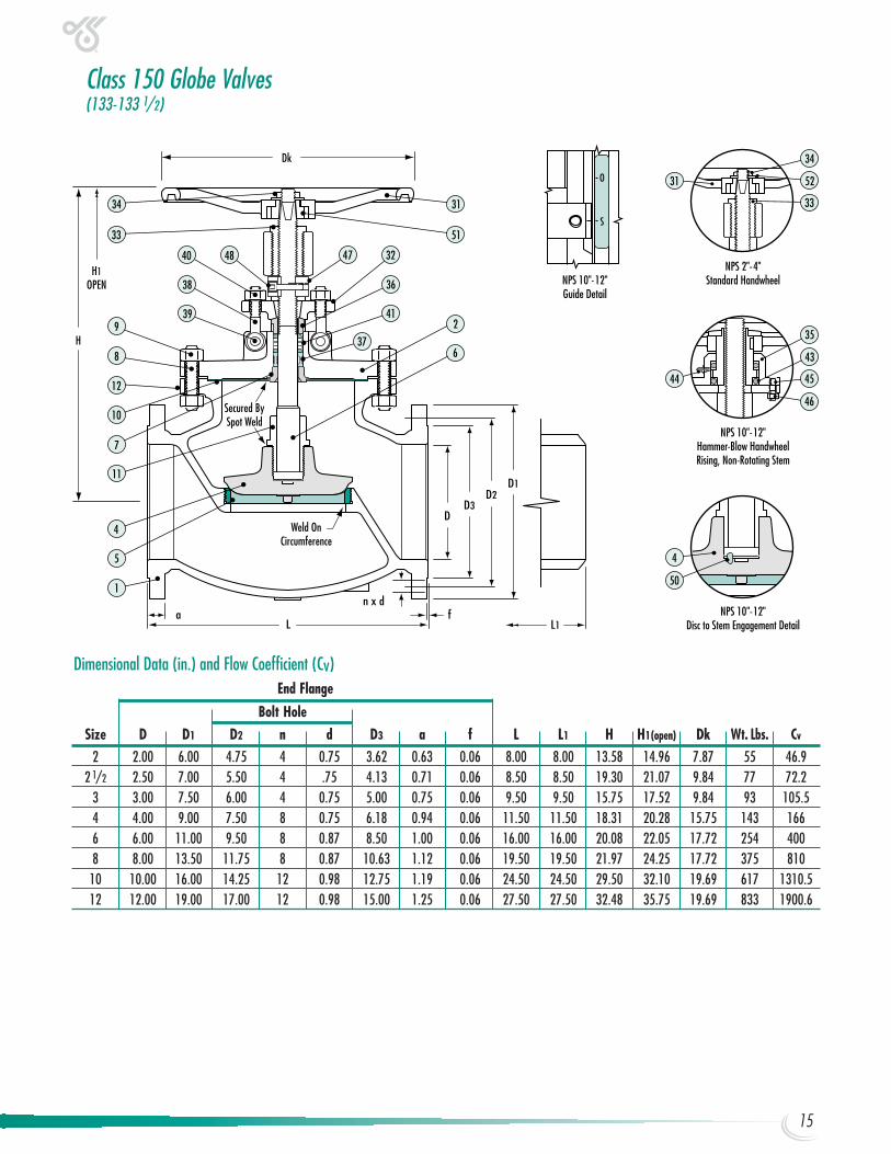
Class 150 Globe Valves(133-133 1/2)
NPS 10"-12"Disc to Stem Engagement Detail
NPS 2"-4"Standard HandwheelNPS 10"-12"
Guide Detail
50
4
34
33
5231
35
44
NPS 10"-12"Hammer-Blow HandwheelRising, Non-Rotating Stem
45
46
43H
D1D2
D3D
Dk
L L1fa
n x d
Weld OnCircumference
Secured BySpot Weld
2
6
31
51
41
37
36
32
34
33
9
12
10
7
8
11
4
1
5
40
39
38H1
OPEN
4748
End Flange
Bolt HoleSize D D1 D2 n d D3 a f L L1 H H1(open) Dk Wt. Lbs. Cv
2 2.00 6.00 4.75 4 0.75 3.62 0.63 0.06 8.00 8.00 13.58 14.96 7.87 55 46.92 1/2 2.50 7.00 5.50 4 .75 4.13 0.71 0.06 8.50 8.50 19.30 21.07 9.84 77 72.2
3 3.00 7.50 6.00 4 0.75 5.00 0.75 0.06 9.50 9.50 15.75 17.52 9.84 93 105.54 4.00 9.00 7.50 8 0.75 6.18 0.94 0.06 11.50 11.50 18.31 20.28 15.75 143 1666 6.00 11.00 9.50 8 0.87 8.50 1.00 0.06 16.00 16.00 20.08 22.05 17.72 254 4008 8.00 13.50 11.75 8 0.87 10.63 1.12 0.06 19.50 19.50 21.97 24.25 17.72 375 810
10 10.00 16.00 14.25 12 0.98 12.75 1.19 0.06 24.50 24.50 29.50 32.10 19.69 617 1310.512 12.00 19.00 17.00 12 0.98 15.00 1.25 0.06 27.50 27.50 32.48 35.75 19.69 833 1900.6
Dimensional Data (in.) and Flow Coefficient (Cv)
15
16
NPS 2"-3"Standard HandwheelRising, Rotating Stem
NPS 10"-12"Hammer-Blow Handwheel With Gear
Rising, Non-Rotating Stem
NPS 8"Guide Detail
34
33
5231
30 31
45
34
52
31
33
NPS 2"-8"Disc to Stem Engagement Detail
NPS 4"-8"Hammer-Blow HandwheelRising, Non-Rotating Stem
51
SecuredBy Weld
SecuredBy Weld
Dk
H
A
AxisOf Stem
33
46
51
34
4
H
Dk
Weld OnCircumference
Secured BySpot Weld
D1D2
D3D
L L1fa
n x d
36
41
37
7
1
2
31
4435
326
34
3343
4645
48
4038
47
4
11
5
50
399
12
8
10
H1OPEN
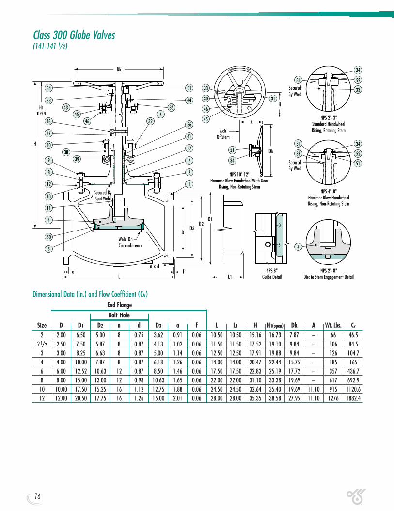
Class 300 Globe Valves(141-141 1/2)
End Flange
Bolt HoleSize D D1 D2 n d D3 a f L L1 H H1(open) Dk A Wt. Lbs. Cv
2 2.00 6.50 5.00 8 0.75 3.62 0.91 0.06 10.50 10.50 15.16 16.73 7.87 – 66 46.52 1/2 2.50 7.50 5.87 8 0.87 4.13 1.02 0.06 11.50 11.50 17.52 19.10 9.84 – 106 84.5
3 3.00 8.25 6.63 8 0.87 5.00 1.14 0.06 12.50 12.50 17.91 19.88 9.84 – 126 104.74 4.00 10.00 7.87 8 0.87 6.18 1.26 0.06 14.00 14.00 20.47 22.44 15.75 – 185 1656 6.00 12.52 10.63 12 0.87 8.50 1.46 0.06 17.50 17.50 22.83 25.19 17.72 – 357 436.78 8.00 15.00 13.00 12 0.98 10.63 1.65 0.06 22.00 22.00 31.10 33.38 19.69 – 617 692.9
10 10.00 17.50 15.25 16 1.12 12.75 1.88 0.06 24.50 24.50 32.64 35.40 19.69 11.10 915 1120.612 12.00 20.50 17.75 16 1.26 15.00 2.01 0.06 28.00 28.00 35.35 38.58 27.95 11.10 1276 1882.4
Dimensional Data (in.) and Flow Coefficient (Cv)
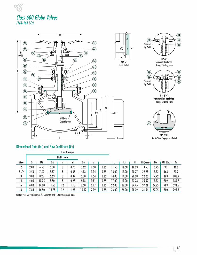
Class 600 Globe Valves(161-161 1/2)
NPS 2"Standard HandwheelRising, Rotating Stem
NPS 6"Guide Detail
34
33
5231
34
52
31
33
NPS 2"-8"Disc to Stem Engagement Detail
4
NPS 3"-4"Hammer-Blow Handwheel
Rising, Rotating Stem
51
SecuredBy Weld
SecuredBy Weld
H
Dk
Weld OnCircumference
Secured BySpot Weld
D1D2
D3D
L L1fa
n x d
34
3343
48 46
4038
47
45
4
5
50
31
44
36
41
37
7
2
1
399
12
8
35
326
10
11
H1OPEN
End Flange
Bolt HoleSize D D1 D2 n d D3 a f L L1 H H1(open) Dk Wt. Lbs. Cv
2 2.00 6.50 5.00 8 0.75 3.62 1.30 0.25 11.50 11.50 16.93 18.50 15.75 95 46.22 1/2 2.50 7.50 5.87 8 0.87 4.13 1.14 0.25 13.00 13.00 20.27 22.25 17.72 163 73.2
3 3.00 8.25 6.63 8 0.87 5.00 1.54 0.25 14.00 14.00 20.28 22.25 17.72 163 103.94 4.00 10.75 8.50 8 0.98 6.18 1.81 0.25 17.00 17.00 23.23 25.59 17.72 309 189.76 6.00 14.00 11.50 12 1.10 8.50 2.17 0.25 22.00 22.00 34.45 37.21 27.95 789 394.58 7.88 16.50 13.75 12 1.25 10.62 2.19 0.25 26.00 26.00 28.39 31.54 22.05 800 795.8
Contact your DSI® salesperson for Class 900 and 1500 Dimensional Data.
Dimensional Data (in.) and Flow Coefficient (Cv)
17
18
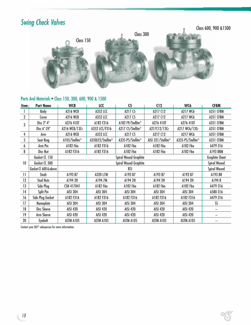
Swing Check Valves
Parts And Materials • Class 150, 300, 600, 900 & 1500Item Part Name WCB LCC C5 C12 WC6 CF8M
1 Body A216 WCB A352 LCC A217 C5 A217 C12 A217 WC6 A351 CF8M2 Cover A216 WCB A352 LCC A217 C5 A217 C12 A217 WC6 A351 CF8M
3 Disc 2"-4" A276 410T A182 F316 A182 F9/Stellite® A276 410T A276 410T A351 CF8MDisc 6"-24" A216 WCB/13Cr A352 LCC/F316 A217 C5/Stellite® A217C12/13Cr A217 WC6/13Cr A351 CF8M
4 Arm A216 WCB A352 LCC A217 C5 A217 C12 A217 WC6 A351 CF8M5 Seat Ring A105/Stellite® A350LF2/Stellite® A335-P5/Stellite® AISI 321/Stellite® A335-P5/Stellite® A351 CF8M6 Arm Pin A182 F6a A182 F316 A182 F6a A182 F6a A182 F6a A479 3168 Disc Nut A182 F316 A182 F316 A182 F6a A182 F6a A182 F6a A193 B8M
Gasket Cl. 150 Spiral Wound Graphite Graphite Sheet10 Gasket Cl. 300 Spiral Wound Graphite Spiral Wound
Gasket Cl. 600 &above RTJ Spiral Wound11 Studs A193 B7 A320 L7M A193 B7 A193 B7 A193 B7 A193 B812 Stud Nuts A194 2H A194 7M A194 2H A194 2H A194 2H A194 813 Side Plug CSN 417041 A182 F6a A182 F6a A182 F6a A182 F6a A479 31614 Split Pin AISI 304 AISI 304 AISI 304 AISI 304 AISI 304 A580 31616 Side Plug Gasket A182 F316 A182 F316 A182 F316 A182 F316 A182 F316 A479 31617 Nameplate AISI 304 AISI 304 AISI 304 AISI 304 AISI 304 SS18 Disc Sleeve AISI 420 AISI 420 AISI 420 AISI 420 AISI 420 –19 Arm Sleeve AISI 420 AISI 420 AISI 420 AISI 420 AISI 420 –20 Eyebolt ASTM A105 ASTM A105 ASTM A105 ASTM A105 ASTM A105 –
Contact your DSI® salesperson for more information.
Class 300Class 600, 900 &1500
Class 150
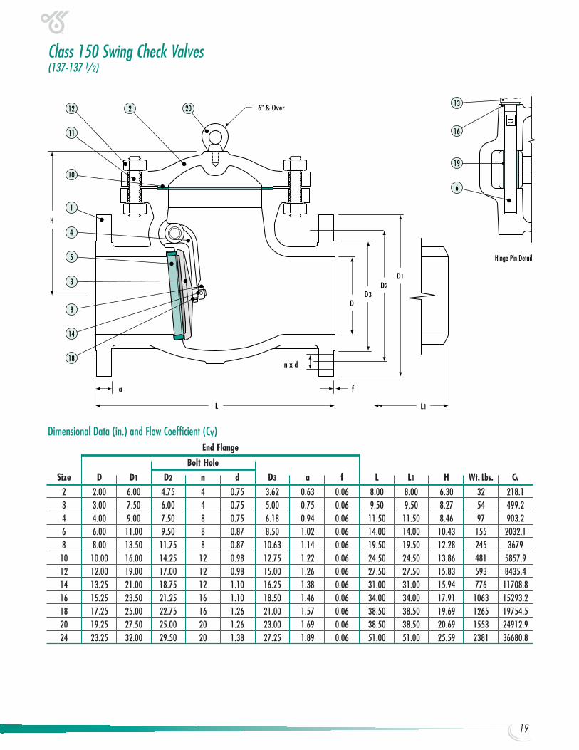
Class 150 Swing Check Valves(137-137 1/2)
H
D1D2
D3D
L L1
fa
n x d
6" & Over
19
16
6
13
11
4
5
10
2012 2
3
18
14
1
8
Hinge Pin Detail
End Flange
Bolt HoleSize D D1 D2 n d D3 a f L L1 H Wt. Lbs. Cv
2 2.00 6.00 4.75 4 0.75 3.62 0.63 0.06 8.00 8.00 6.30 32 218.13 3.00 7.50 6.00 4 0.75 5.00 0.75 0.06 9.50 9.50 8.27 54 499.24 4.00 9.00 7.50 8 0.75 6.18 0.94 0.06 11.50 11.50 8.46 97 903.26 6.00 11.00 9.50 8 0.87 8.50 1.02 0.06 14.00 14.00 10.43 155 2032.18 8.00 13.50 11.75 8 0.87 10.63 1.14 0.06 19.50 19.50 12.28 245 3679
10 10.00 16.00 14.25 12 0.98 12.75 1.22 0.06 24.50 24.50 13.86 481 5857.912 12.00 19.00 17.00 12 0.98 15.00 1.26 0.06 27.50 27.50 15.83 593 8435.414 13.25 21.00 18.75 12 1.10 16.25 1.38 0.06 31.00 31.00 15.94 776 11708.816 15.25 23.50 21.25 16 1.10 18.50 1.46 0.06 34.00 34.00 17.91 1063 15293.218 17.25 25.00 22.75 16 1.26 21.00 1.57 0.06 38.50 38.50 19.69 1265 19754.520 19.25 27.50 25.00 20 1.26 23.00 1.69 0.06 38.50 38.50 20.69 1553 24912.924 23.25 32.00 29.50 20 1.38 27.25 1.89 0.06 51.00 51.00 25.59 2381 36680.8
Dimensional Data (in.) and Flow Coefficient (Cv)
19
14
H
D1D2
D3D
L L1
fa
n x d
6" & Over
19
16
6
13
11
4
5
10
2012 2
3
18
14
1
8
Hinge Pin Detail
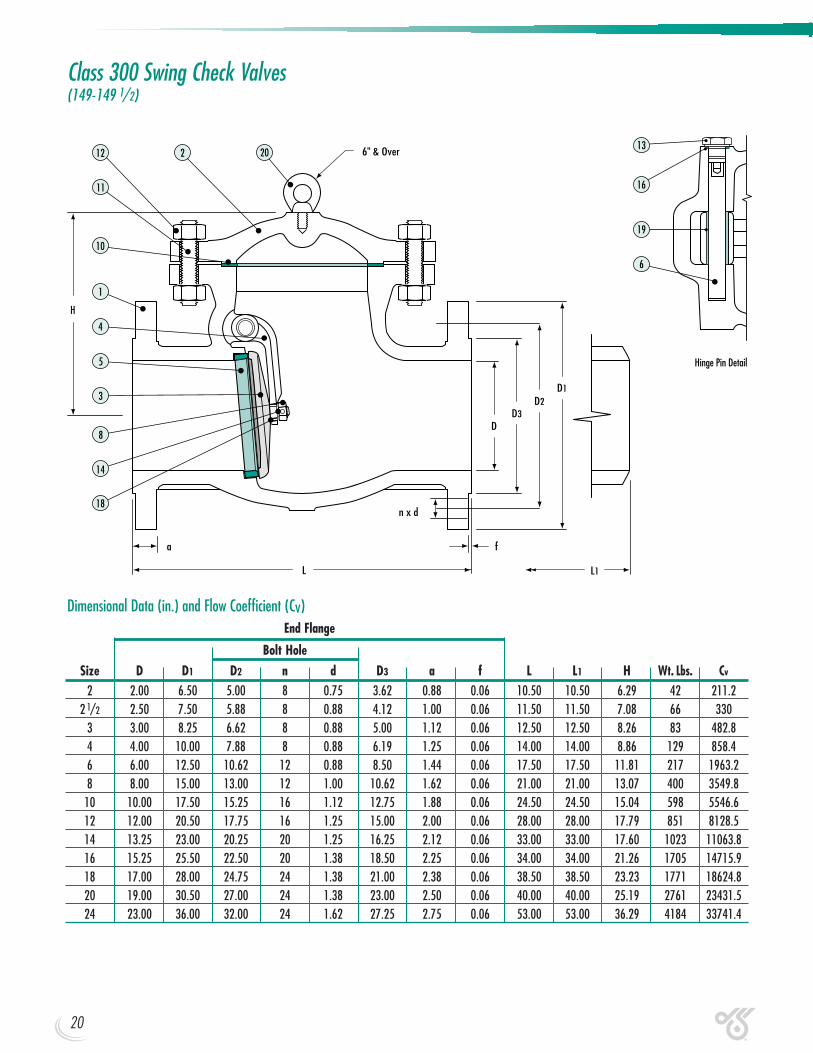
Class 300 Swing Check Valves(149-149 1/2)
End Flange
Bolt HoleSize D D1 D2 n d D3 a f L L1 H Wt. Lbs. Cv
2 2.00 6.50 5.00 8 0.75 3.62 0.88 0.06 10.50 10.50 6.29 42 211.22 1/2 2.50 7.50 5.88 8 0.88 4.12 1.00 0.06 11.50 11.50 7.08 66 330
3 3.00 8.25 6.62 8 0.88 5.00 1.12 0.06 12.50 12.50 8.26 83 482.84 4.00 10.00 7.88 8 0.88 6.19 1.25 0.06 14.00 14.00 8.86 129 858.46 6.00 12.50 10.62 12 0.88 8.50 1.44 0.06 17.50 17.50 11.81 217 1963.28 8.00 15.00 13.00 12 1.00 10.62 1.62 0.06 21.00 21.00 13.07 400 3549.8
10 10.00 17.50 15.25 16 1.12 12.75 1.88 0.06 24.50 24.50 15.04 598 5546.612 12.00 20.50 17.75 16 1.25 15.00 2.00 0.06 28.00 28.00 17.79 851 8128.514 13.25 23.00 20.25 20 1.25 16.25 2.12 0.06 33.00 33.00 17.60 1023 11063.816 15.25 25.50 22.50 20 1.38 18.50 2.25 0.06 34.00 34.00 21.26 1705 14715.918 17.00 28.00 24.75 24 1.38 21.00 2.38 0.06 38.50 38.50 23.23 1771 18624.820 19.00 30.50 27.00 24 1.38 23.00 2.50 0.06 40.00 40.00 25.19 2761 23431.524 23.00 36.00 32.00 24 1.62 27.25 2.75 0.06 53.00 53.00 36.29 4184 33741.4
Dimensional Data (in.) and Flow Coefficient (Cv)
20
14
H
D1D2
D3D
L L1
fa
n x d
6" & Over
19
16
6
13
11
4
5
2012 2
3
18
14
1
8
10
Hinge Pin Detail
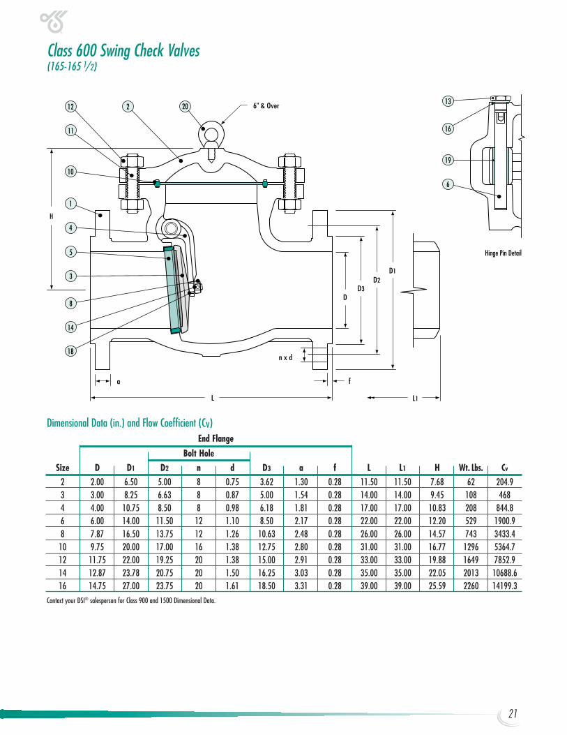
Class 600 Swing Check Valves(165-165 1/2)
End Flange
Bolt HoleSize D D1 D2 n d D3 a f L L1 H Wt. Lbs. Cv
2 2.00 6.50 5.00 8 0.75 3.62 1.30 0.28 11.50 11.50 7.68 62 204.93 3.00 8.25 6.63 8 0.87 5.00 1.54 0.28 14.00 14.00 9.45 108 4684 4.00 10.75 8.50 8 0.98 6.18 1.81 0.28 17.00 17.00 10.83 208 844.86 6.00 14.00 11.50 12 1.10 8.50 2.17 0.28 22.00 22.00 12.20 529 1900.98 7.87 16.50 13.75 12 1.26 10.63 2.48 0.28 26.00 26.00 14.57 743 3433.4
10 9.75 20.00 17.00 16 1.38 12.75 2.80 0.28 31.00 31.00 16.77 1296 5364.712 11.75 22.00 19.25 20 1.38 15.00 2.91 0.28 33.00 33.00 19.88 1649 7852.914 12.87 23.78 20.75 20 1.50 16.25 3.03 0.28 35.00 35.00 22.05 2013 10688.616 14.75 27.00 23.75 20 1.61 18.50 3.31 0.28 39.00 39.00 25.59 2260 14199.3
Contact your DSI® salesperson for Class 900 and 1500 Dimensional Data.
Dimensional Data (in.) and Flow Coefficient (Cv)
21
22
For years Industry professionals have specified DSI® valve products for theirmost demanding projects, and consistently Zy-Tech Global Industries deliversthe highest performance fluid control products available anywhere.
Ask your DSI® representative about our other fine flow control products.
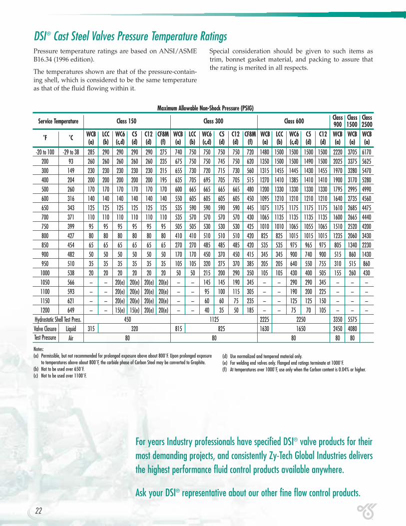
Pressure temperature ratings are based on ANSI/ASMEB16.34 (1996 edition).
The temperatures shown are that of the pressure-contain-ing shell, which is considered to be the same temperatureas that of the fluid flowing within it.
Notes:(a) Permissible, but not recommended for prolonged exposure above about 800˚F. Upon prolonged exposure
to temperatures above about 800˚F, the carbide phase of Carbon Steel may be converted to Graphite.(b) Not to be used over 650˚F.(c) Not to be used over 1100˚F.
Special consideration should be given to such items astrim, bonnet gasket material, and packing to assure thatthe rating is merited in all respects.
Maximum Allowable Non-Shock Pressure (PSIG)
Service Temperature Class 150 Class 300 Class 600 Class Class Class900 1500 2500
˚F ˚C WCB LCC WC6 C5 C12 CF8M WCB LCC WC6 C5 C12 CF8M WCB LCC WC6 C5 C12 WCB WCB WCB(a) (b) (c,d) (d) (d) (f) (a) (b) (c,d) (d) (d) (f) (a) (b) (c,d) (d) (d) (a) (a) (a)
-20 to 100 -29 to 38 285 290 290 290 290 275 740 750 750 750 750 720 1480 1500 1500 1500 1500 2220 3705 6170200 93 260 260 260 260 260 235 675 750 750 745 750 620 1350 1500 1500 1490 1500 2025 3375 5625300 149 230 230 230 230 230 215 655 730 720 715 730 560 1315 1455 1445 1430 1455 1970 3280 5470400 204 200 200 200 200 200 195 635 705 695 705 705 515 1270 1410 1385 1410 1410 1900 3170 5280500 260 170 170 170 170 170 170 600 665 665 665 665 480 1200 1330 1330 1330 1330 1795 2995 4990600 316 140 140 140 140 140 140 550 605 605 605 605 450 1095 1210 1210 1210 1210 1640 2735 4560650 343 125 125 125 125 125 125 535 590 590 590 590 445 1075 1175 1175 1175 1175 1610 2685 4475700 371 110 110 110 110 110 110 535 570 570 570 570 430 1065 1135 1135 1135 1135 1600 2665 4440750 399 95 95 95 95 95 95 505 505 530 530 530 425 1010 1010 1065 1055 1065 1510 2520 4200800 427 80 80 80 80 80 80 410 410 510 510 510 420 825 825 1015 1015 1015 1235 2060 3430850 454 65 65 65 65 65 65 270 270 485 485 485 420 535 535 975 965 975 805 1340 2230900 482 50 50 50 50 50 50 170 170 450 370 450 415 345 345 900 740 900 515 860 1430950 510 35 35 35 35 35 35 105 105 320 275 370 385 205 205 640 550 755 310 515 8601000 538 20 20 20 20 20 20 50 50 215 200 290 350 105 105 430 400 505 155 260 4301050 566 – – 20(e) 20(e) 20(e) 20(e) – – 145 145 190 345 – – 290 290 345 – – –1100 593 – – 20(e) 20(e) 20(e) 20(e) – – 95 100 115 305 – – 190 200 225 – – –1150 621 – – 20(e) 20(e) 20(e) 20(e) – – 60 60 75 235 – – 125 125 150 – – –1200 649 – – 15(e) 15(e) 20(e) 20(e) – – 40 35 50 185 – – 75 70 105 – – –
Hydrostatic Shell Test Press. 450 1125 2225 2250 3350 5575Valve Closure Liquid 315 320 815 825 1630 1650 2450 4080Test Pressure Air 80 80 80 80 80
DSI® Cast Steel Valves Pressure Temperature Ratings
(d) Use normalized and tempered material only.(e) For welding end valves only. Flanged end ratings terminate at 1000˚F.(f) At temperatures over 1000˚F, use only when the Carbon content is 0.04% or higher.
Zy-Tech Global Industries, Inc. is dedicated to continuallyimproving their state-of-the-art engineering and manufac-turing capabilities to improve the overall quality of theirproducts and customer service. Zy-Tech’s entire global net-work of flow control experts consist of highly trained tech-nicians, engineers, and superior testing laboratories toensure that all products supplied to our customers are 100%in accordance with industry standards as well as our ownQuality Management System.
WarrantyFor a period of (18) months from date of purchase or for a period of (12) months from date of installation of any ofthe goods described herein, whichever period comes first expires, ZY-TECH GLOBAL INDUSTRIES (Seller) war-rants such goods shall remain free from failure due to defects in workmanship and material incorporated therein byor for ZY-TECH GLOBAL INDUSTRIES (Seller) provided such failure shall not have been caused or contributed to,by improper usage, service or application, improper installation, maintenance, repairs, alterations, or modificationseffected by or for the user negligence or obligations hereunder, and provided written notification of such failure shallbe immediately given to ZY-TECH GLOBAL INDUSTRIES at the following address: ZY-TECH GLOBAL INDUS-TRIES, 10600 Corporate Drive, Stafford, TX 77477.ZY-TECH GLOBAL INDUSTRIES agrees to repair, or at its sole option, to replace the goods sold at its sole expense.Apart from the warranty and undertakings of above set forth, ZY-TECH GLOBAL INDUSTRIES assumes no obligation or lia-bility for losses, expense, or damages, direct or consequential, suffered or incurred as a result of any failure of, or defect in, thegoods described herein, including but not limited to, such costs, expenses or damages as may result from the necessityto remove, replace, restore or transport the goods from any location or service in which they may be used, regard-less of the cause of such failure or defect.This warranty is the only warranty made by ZY-TECH GLOBAL INDUSTRIES in connection herewith. There are not otherwarranties, express or implied, of any kind given with respect to the goods, their merchantability, fitness for any particular pur-pose or usage, or otherwise, nor is any person authorized to extend on behalf of ZY-TECH GLOBAL INDUSTRIES any formof warranty other than that above set forth.
The goods described herein are not sold or distributed by ZY-TECH GLOBAL INDUSTRIES for personal, family orhousehold purposes, nor are they normally suited for use as such.
Return Goods Policy1) Material returned to Zy-Tech Global Industries must be
accompanied with an authorized Return Goods Authorization (RGA).
2) Material received with proper authorization is subject to Inspection & Final Disposition by Zy-Tech Global Industries Quality Department.
3) Special items, buyouts, and modified productsare non-returnable.
4) Returns are not accepted after sixty (60) days of shipment.
5) Standard Restocking Charge for returned materialsis 15% with a $125.00 minimum.
6) Freight for material being returned to Zy-Tech Global Industries to be prepaid.
7) If clean up or re-certification is required, chargeswill be deducted from the applicable credit.
8) Cancellation of orders prior to shipment and/or stock transferred to a branch may incur a minimum10% Cancellation Charge.
Warranty And Return Policy
Our Quality Commitment...
Note: This catalog is for reference only. All information issubject to change without notice.
23
Contact yourlocal Zy-Techrepresentativefor more informationabout other DSI® Brandflow control products,or visit our website atwww.zy-tech.com
©2002 Zy-Tech Global Industries, Inc. • DSI® is a registered trademark of Zy-tech Global Industries, Inc. • ZGI-DSI-CSV-5/02Grafoil® is a registered trademark of Union Carbide Corporation. • Stellite® is a registered trademark of Stoody Deloro Stellite, Inc. • Teflon® is a registered trademark of DuPont.
Contact yourlocal Zy-Techrepresentativefor more informationabout other DSI® Brandflow control products,or visit our website atwww.zy-tech.com
10600 Corporate Drive, Stafford, Texas 77477(281) 565-1010 • (800) 231-3530 • Fax (281) 565-3171
Your Local Representative


![Chapter 17 PROJECT-BASED VOUCHER (PBV)AND RENTAL ...Section 8)/Kansas City HCV … · Description of the HAKC PBV Program Commitment and Priorities [24 CFR 983.5] HAKC’s PBV program](https://img.pdfslide.net/doc/110x75/5fac32f1fcb492674000079e/chapter-17-project-based-voucher-pbvand-rental-section-8kansas-city-hcv.jpg)