Embed Size (px)
Citation preview
PC BASED SMALL ARM ROBOT
MUHAMMAD ZULHILMI BIN MANSOR
A report submitted in partial fulfillment of the requirements for the award of the degree of
Bachelor of Electrical Engineering (Electronics)
Faculty of Electrical and Electronics Engineering
Universiti Malaysia Pahang
NOVEMBER 2010
“I hereby acknowledge that the scope and quality of this thesis is qualified for the award
of the Bachelor Degree of Electrical Engineering (Electronics)”
Signature : ______________________________
Name : AIRUL SHARIZLI BIN ABDULLAH
Date : 26 NOVEMBER 2010
“All the trademark and copyrights use herein are property of their respective owner.
References of information from other sources are quoted accordingly; otherwise the
information presented in this report is solely work of the author.”
Signature : ____________________________
Author : MUHAMMAD ZULHILMI BIN MANSOR
Date : 26 NOVEMBER 2010
ACKNOWLEDGEMENT
Alhamdulillah, first of all I would like to thanks a lot to Allah S.W.T for
blessing me with good health, physical and mental and time, also giving me patient and
spirit through this starting of my final year project. With mercifulness from Allah
S.W.T, therefore I can start to create a useful and brilliance idea to this project.
To my beloved parent, Mansor Bin Kembar and Ramisah Binti Awang, I am
grateful to have both of you in my life and giving support through this life. I am also
wanted to thank my supervisor, Mr. Airul Sharizli Bin Abdullah and Mr. Fairuz Reza
Bin Rashidi, the lecturer from the Faculty of Electric and Electronic that also as my
Academic Advisor, for his advice, comment and generous support. Thanks for your
guidance and without your guidance this project cannot be started and will not well
organized.
Not forget, to all my friends, especially to my Bachelor of Electrical
(Electronics) BEE, especially Mohd Amirul Aiman, Khairul, Khairul Anuar, Wan Mohd
Nur Hasif, Thanachelvan, and Muhammad Hafiz, who is part of my members of same
under supervisor that help me a lot in this making of this final project. May us all are
going through this final project together and success together.
I also would like to thank all parties that involved in my final project, whether
directly or indirectly in helping me to start this project and for their invaluable time,
guidance and advice. That support although small, but it means a lot to me in order to
make sure this project will be successful.
For the last, I will prepare my mind and body to face anything that coming in my
way to finish this project. Thank you very much and may Allah S.W.T bless all of you.
ABSTRACT
PC Based Small Arm Robot project is represented a small arm robot that controlled by Personal Computer (PC) using Graphical User Interface (GUI). The idea behind this project is able to enhance the student knowledge about industrial robot application. Basically, this project is focused on the designing the system include controlling elements. The project was involving mechanical part, hardware and software. These three elements are the main system of this project. A small arm robot is a mechanical part that represented the system output overall. Besides that, the Graphical User Interface (GUI) is developed by using Visual Basic software acted as the panel control through the personal computer (PC). The hardware element of the project is microcontroller circuit in order to manipulate and control the final system. As the additional information, a small arm robot has five degree of freedom (DOF) based on human’s arm. These all degree of freedoms is functioned as joint which is base, shoulder, elbow, wrist and end-effectors. The small arm robot is totally run by servo motors. For this project, the system is interfaced by using Atmel microcontroller. The Atmel microcontroller can manipulate the movement of small arm robot according to the Graphical User Interface (GUI) data signal. Data signal from personal computer (PC) triggered the function program code in microcontroller as the output signal that controls the servo motor rotational motions. Communication between personal computer (PC) and microcontroller circuit is connected by the serial communication integrated circuit (IC) that combined with microcontroller board.
ABSTRAK
PC Based Small Arm Robot merupakan sebuah projek mengaplikasikan robot lengan kecil yang dikawal oleh komputer (PC) dengan menggunakan Graphical User Interface (GUI). Matlamat sebenar projek ini adalah berupaya untuk membantu menambahkan pengetahuan pelajar tentang aplikasi robot industri. Projek ini pada asasnya memfokuskan tentang pembinaan sistem termasuklah elemen pengawalannya. Projek ini melibatkan pembinaan bahagian mekanikal, hardware dan software. Ketiga-tiga elemen ini merupakan sistem yang terpenting dalam projek ini. Robot lengan kecil ini merupakan bahagian mekanikal yang menggambarkan output keseluruhan sistem. Selain daripada itu, Graphical User Interface (GUI) dibangunkan dengan menggunakan perisian Visual Basic yang bertindak sebagai panel kawalan melalui komputer (PC). Elemen hardware dalam projek ini ialah litar microcontroller yang mana dapat memanipulasi dan mengawal keseluruhan sistem akhir. Sebagai maklumat tambahannya, robot lengan kecil ini mempunyai lima sudut kebebasan atau lebih di kenali dengan degree of freedom (DOF) yang berpandukan kepada lengan manusia. Kesemua sudut kebebasan ini (DOF) berfungsi sebagai sendi lengan manusia seperti bahu, siku, pergelangan tangan dan faktor terakhir. Robot lengan kecil ini keseluruhannya digerakkan dengan menggunakan servo motor. Sistem untuk projek ini diperantarakan dengan menggunakan Atmel microcontroller. Atmel microcontroller dapat memanipulasi pergerakan robot lengan kecil berdasarkan kepada isyarat data Graphical User Interface (GUI). Isyarat data daripada komputer (PC) mendetik fungsi kod program di dalam microcontroller sebagai isyarat keluaran yang dapat mengawal pergerakan pusingan servo motor. Komunikasi antara komputer (PC) dan litar microcontroller disambungkan dengan sebuah litar bersepadu komunikasi siri yang bergabung dengan litar microcontroller.
TABLE OF CONTENTS
CHAPTER TITLE PAGE
SUPERVISOR’S DECLARATION ii
STUDENTS’S DECLARATION iii
DEDICATION iv
ACKNOWLEDGEMENTS vi
ABSTRACT vi
ABSTRAK vii
TABLE OF CONTENTS viii LIST OF TABLES xi
LIST OF FIGURES xii
LIST OF ABBREVIATIONS xiv
1 INTRODUCTION
1.1 Background of Project 1
1.2 Project Objective 2
1.3 Problem Statement 2
1.4 Project Scope 2
1.5 Thesis Outline 3
2 LITERATURE REVIEW
2.1 Robot Definition 4
2.2 Industrial Arm Robot 7
2.3 Literature Survey 8
TABLE OF CONTENTS
CHAPTER TITLE PAGE
3 METHODOLOGY
3.1 Introduction 11
3.2 Project Flow and Block Diagram 12
3.3 Priminilary Study 14
3.4 Mechanical Part Designing and Development
3.4.1 Small Arm Robot Designing 15
3.4.2 Robot Casing Designing 19
3.5 Hardware Designing and Development
3.5.1 Circuit Designing 21
3.5.2 Servo Motor Interface 28
3.6 Software Designing and Development
3.6.1 Microcontroller Software Designing and
Development 32
3.6.2 Graphical User Interface (GUI) Deigning and
Development 34
3.7 Testing Overall System
3.7.1 Basic Circuit 40
3.7.2 Microcontroller Port 41
3.7.3 Serial Communication Circuit 42
3.7.4 Servo Motor 44
3.7.5 Graphical User Interface (GUI) and
Microcontroller Software 45
TABLE OF CONTENTS
CHAPTER TITLE PAGE
4 RESULT AND DISCUSSION
4.1 Introduction 50
4.2 Result 50
4.3 Discussion 62
5 CONCLUSION
5.1 Conclusion 65
6 FUTURE RECOMMENDATION
6.1 Future Recommendation 66
REFFERENCES 68
APPENDIX A 69
APPENDIX B 71
APPENDIX C 73
APPENDIX D 79
APPENDIX E 84
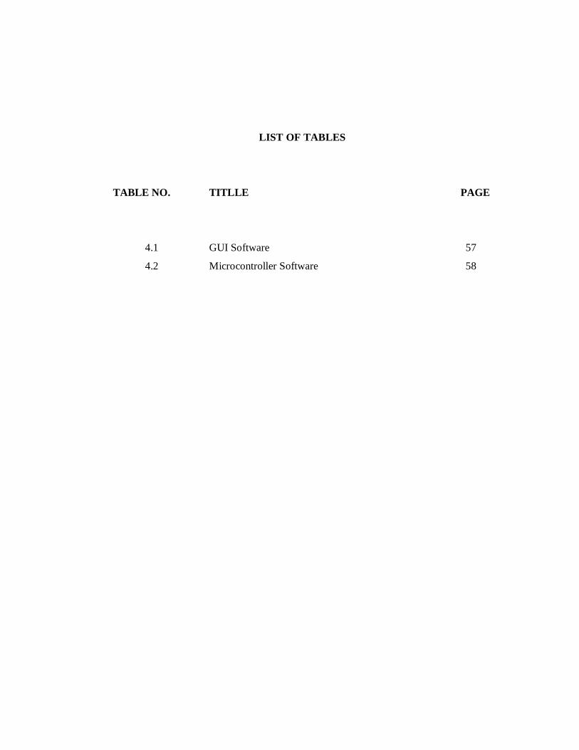
LIST OF TABLES
TABLE NO. TITLLE PAGE
4.1 GUI Software 57
4.2 Microcontroller Software 58
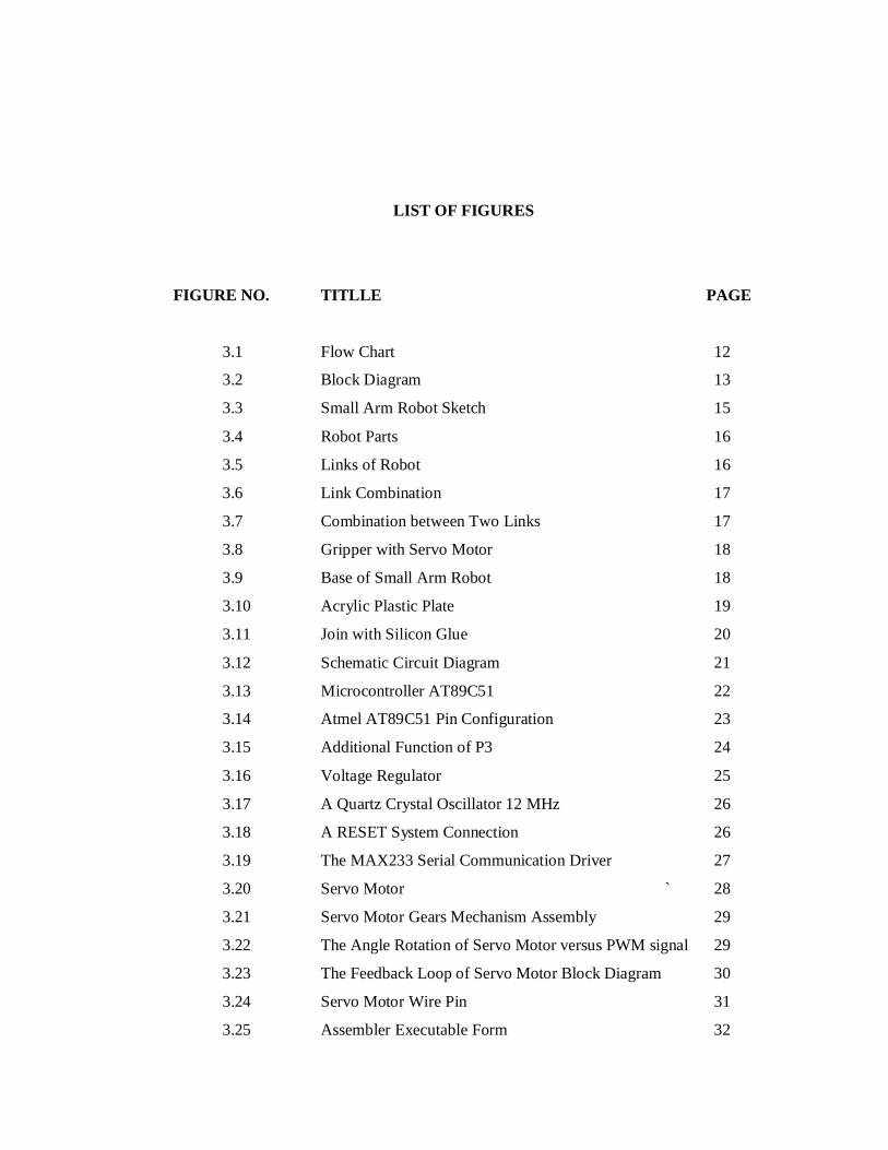
LIST OF FIGURES
FIGURE NO. TITLLE PAGE
3.1 Flow Chart 12
3.2 Block Diagram 13
3.3 Small Arm Robot Sketch 15
3.4 Robot Parts 16
3.5 Links of Robot 16
3.6 Link Combination 17
3.7 Combination between Two Links 17
3.8 Gripper with Servo Motor 18
3.9 Base of Small Arm Robot 18
3.10 Acrylic Plastic Plate 19
3.11 Join with Silicon Glue 20
3.12 Schematic Circuit Diagram 21
3.13 Microcontroller AT89C51 22
3.14 Atmel AT89C51 Pin Configuration 23
3.15 Additional Function of P3 24
3.16 Voltage Regulator 25
3.17 A Quartz Crystal Oscillator 12 MHz 26
3.18 A RESET System Connection 26
3.19 The MAX233 Serial Communication Driver 27
3.20 Servo Motor ` 28
3.21 Servo Motor Gears Mechanism Assembly 29
3.22 The Angle Rotation of Servo Motor versus PWM signal 29
3.23 The Feedback Loop of Servo Motor Block Diagram 30
3.24 Servo Motor Wire Pin 31
3.25 Assembler Executable Form 32
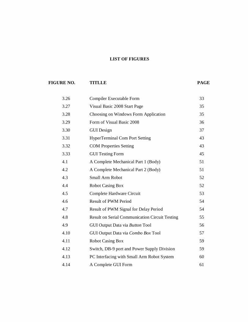
LIST OF FIGURES
FIGURE NO. TITLLE PAGE
3.26 Compiler Executable Form 33
3.27 Visual Basic 2008 Start Page 35
3.28 Choosing on Windows Form Application 35
3.29 Form of Visual Basic 2008 36
3.30 GUI Design 37
3.31 HyperTerminal Com Port Setting 43
3.32 COM Properties Setting 43
3.33 GUI Testing Form 45
4.1 A Complete Mechanical Part 1 (Body) 51
4.2 A Complete Mechanical Part 2 (Body) 51
4.3 Small Arm Robot 52
4.4 Robot Casing Box 52
4.5 Complete Hardware Circuit 53
4.6 Result of PWM Period 54
4.7 Result of PWM Signal for Delay Period 54
4.8 Result on Serial Communication Circuit Testing 55
4.9 GUI Output Data via Button Tool 56
4.10 GUI Output Data via Combo Box Tool 57
4.11 Robot Casing Box 59
4.12 Switch, DB-9 port and Power Supply Division 59
4.13 PC Interfacing with Small Arm Robot System 60
4.14 A Complete GUI Form 61
LIST OF ABBREVIATIONS
PC Personal Computer
GUI Graphical User Interface
VB Visual Basic
PWM Pulse Width Modulation
LED Light Emitting Diode
CHAPTER 1
INTRODUCTION
1.1 BACKGROUND OF PROJECT
PC Based Small Arm Robot is described as a model for arm robot that controlled
by PC using Graphical User Interface (GUI) software. A robot has 4-axis and one end-
effector or manipulator that functions as joint to make movement like human’s arm that
each joint completed by servo motors. Data are sent through the Graphical User
Interface (GUI) that interfacing with personal computer (PC) to control the output, a
small arm robot. The end-effector for this small arm robot was gripper.
For this project, the overall system is controlled by using Atmel microcontroller.
The Atmel microcontroller function as controller where all the data that send by user
using GUI software will be process first before it can manipulate the servo motors to
run whatever condition, for example the degree of motor movements or angular motor
shaft position. Both programming code for GUI software and microcontroller are totally
different. The PC Based Small Arm Robot is the integrated project because the
combination of hardware, GUI software and microcontroller software.
1.2 PROJECT OBJECTIVE
The objective of this project is to;
i- Design and develop circuit for interfacing microcontroller
with five servo motor including one gripper.
ii- Design and develop Graphical User Interface (GUI) using
Visual Basic software.
iii- Develop small scale PC Based Small Arm Robot.
1.3 PROBLEM STATEMENT
The problem statements of this project are;
i- Small arm robot as model learning kit to create multiple
applications.
ii- More knowledge and skills in hardware designing.
iii- Reduce dependence on human work to save energy, cost
and time.
1.4 PROJECT SCOPE
The scope of this project is to;
i. Design and construct mechanical parts of robot. It is
consist of 4-axis joint and one gripper.
ii. Build microcontroller assembly programming. The
assembly programming is for servo motor movement.
iii. Build a visual basic interfacing assembly programming.
The Graphical User Interface (GUI) is design using this
software.
1.5 THESIS OUTLINE
This thesis contains 6 chapters and they are outlined as below:
Chapter 1 explains the introduction that includes concept of PC based system. It also
outlines objective and scope of this system.
Chapter 2 describes the revision about literature review and relationship with this
project development.
Chapter 3 provides description about methodology and discussion on the architecture
used and gives a brief review of microcontroller system board architecture.
Chapter 4 presents the result and discussion that conducted to each module. This chapter
includes the integrated system testing which all the modules are combined.
Chapter 5 summarizes the overall conclusion for this project.
Chapter 6 explains about features recommendation for this project.
CHAPTER 2
LITERATURE REVIEW
2.1 ROBOT DEFINITION
Generally, robot can be defined as a programmable device. It is the combination
of mechanical, electrical and electronic elements. Besides that, it is a machine that
functions in place of a living agent. Robots are especially desirable for certain work
functions because, unlike humans, they never get tired. For the examples, they can
endure physical conditions that are uncomfortable or even dangerous, they can operate
in airless conditions and they do not get bored by repetition. There will be save the
human energy and time.
There are many definitions of robots. It seems to be of difficulty to suggest an
accurate meaning for the word robot, that there are various definitions of this word,
different according to the points of view. Some view a robot through the aspect of
reprogramability while others more concern on the manipulation of the robot, behavior,
intelligence and so on.
The British Robot Association (BRA) defines robot as a programmable device
with a minimum of four degrees of freedom designed to both manipulate and transport
parts, tools or specialized manufacturing implements through variable programmed
motion for the performance of the specific manufacturing task.
While the Robotic Institute of America, on the other hand defines the robot as a
reprogrammable multifunctional manipulator designed to move material, parts, tools or
specialized devices through variable programmed motion for the performance of a
variety of tasks.
Based on the definition of robot by the two institutes, it can be concluded that a
robot must be an automatic machine and be able to deal with the changing information
received from the environment.
2.1.1 Word History
The word robot comes from the Czech word robota (compare with the Russian
rabota for "to work") meaning "drudgery", "servitude", or "forced labor", especially the
so-called "labor rent" that survived in the Austro-Hungarian Empire until 1848.
Isaac Asimov, coined the word robotics as the science of the study of robots, in
his science fiction stories about robot in 1940s.Where in Europe, robotics is define as
‘the science of robotology’ and robotology is defines as ‘the means by which robot
machines are put together and made to work’.
Many people think of robotics as a single area of technology, but in fact robotics
encompasses such diverse areas of technology as mechanical, electrical, electronics,
systems, computer, hardware and software and a host of other advanced technology.
2.1.2 The Distinction between Automation and Robotics
'Robots' is only a small sub-set of the technologies covered by the much broader
term Automation'. 'Automation' refers to a mode of operation in which any machine or
piece of equipment is capable of working without human intervention. Originally,
automation was limited in its potential, as automatic machines could only replace
physical effort and not mental effort.
Robots are just one example of flexible automation. Other examples in the
industrial sector are NC machine tools, automated assembly machines (including
automated component insertion machines), automated guided vehicles (AGV's)
automated storage and retrieval systems (ASRS's), co-ordinate measuring machines
(CMM's) laser / plasma / water jet cutting machines etc.
The terms 'robot' and ‘robotics' both therefore originated in science fiction and
the original perception was one of human-like machines or androids. In popular culture,
and particularly in films, robots are often considered to have all the human attributes
with some capabilities considerably enhanced over that normally found in humans, but
in reality current technology is not yet able to match this vision.
2.2 INDUSTRIAL ARM ROBOT
An industrial robot is officially defined by International Standardization
Organization (ISO) as an automatically controlled, reprogrammable, multipurpose
manipulator programmable in three or more axes. The field of industrial robotics may
be more practically defined as the study, design and use of robot systems for
manufacturing.
Typical applications of industrial robots include welding, painting, ironing,
assembly, pick and place, palletizing, product inspection, and testing, all accomplished
with high endurance, speed, and precision. Manufacturers of industrial robots include
ABB (ASEA Brown-Boveri), Intelligent Actuator, Adept, Epson Robots, and Yaskawa-
Motoman.
ABB is a leading supplier of robots and automation for automotive,
manufacturing and the consumer goods industry. ABB produced its first robot in 1974.
At that time, the company's robots were mainly used for machine tending and material
handling. Nearly 30 years later, that market accounts for some 30 percent of robots sold
worldwide. According to the International Federation of Robotics, welding-spot and arc,
particularly in the automotive industry, is today's largest robot application.
2.3 LITERATURE SURVEY
From the review of some articles and journals, there is some knowledge that can
be related to the PC Based Small Arm Robot project. The overall thesis project mainly
focuses on how to control an arm robot. The first journal “Q-Robot A Multitasking PC
Based Robot Control System” written by N.Costescu, M.Loffler, E.Zergeroglu and
D.Dawson form Department of Electrical and Computer Engineering, Clemson
University, Clemson, SC 29634, USA [1]. Based on this journal, PUMA robot is used as
arm robot.
The thesis of this paper used PUMA robot as the arm robot in order to complete
the purpose of the project. Actually, PUMA word is an abbreviation of Programmable
Universal Machine for Assembly. It is widely used in industry especially automobile
industry. A standard PUMA robot manipulator is controlled by a VAL-II based
Unimation Mark II controller. There are several disadvantages or limitations of the
VAL-II based Mark II controller system, many of which are attributable to the age of
the product. The proposed PC-based control system involves a hardware retrofit of the
Mark II controller, low level control software development, and high level application
program interface and trajectory generation software development. [1] This journal
applies the software to control the movement of arm robot.
The combination of the following three technical developments has made the
PC-based QRobot PUMA retrofit possible: i) the advent of high-speed, PC-based
microcomputer CPUs, ii) the availability of a hardware interface that can connect an
external controlling computer directly to the PUMA servo amplifiers and arm cable in
the existing Mark II controller, and iii) the availability of hard real time operating
systems for PCs (e.g., the QNX operating system). Specifically, the availability of
cheap, powerful PCs and efficient PC real-time operating systems make the
implementation of a PC-based robot control system possible; moreover, the TRC board
set for the Mark II controller makes a PC-based retrofit quite painless. [1]
Besides that, there are several data that can be related to the project from the
second journal written by Daniel G.Bihn and T.C Steve Hsia with thesis title about
“Universal Six-Joint Robot Controller” [2]. This project was to design and implement a
computer-based robotic controller that allows the researcher to write programs and
implement algorithms that control the robot arm from the lowest level of the closed-
loop servo system to the higher levels of kinematics, dynamics, path planning, and
robot language. The use of a familiar software environment was chosen with the intent
of making the user interface as clean and simple as possible. This paper presents the
design and implementation of the controller consisting of the Joint Interface Board (JIB)
electronics and the operating system interface to this hardware. A simple low-level six-
joint PID (proportional-integral-derivative) controller is implemented and presented to
serve as both a functional test of the system and as an application example. [2]
From the third journal of “Hardware and Software Co-design for Robot Arm
Position Control Using VHDL & FPGA”, authors by Mrs.Urmila Meshram, M.Tech.
VLSI Design Student, RKNEC, Nagpur, India, Mr.Pankaj Bande, Embedded System
Designer, LARE, Mumbai, India and Prof. R. R. Harkare, Asst. Prof. E&TC RKNEC,
Nagpur (MH), India [3] basically focuses on hardware and software interfacing for robot
arm controller application. The project of this paper is using FPGA chip in order to
control the arm robot. The purpose of this project is to design and build a control system
for position control for robot arm with an FPGA chip. This is closed loop control
system. In which Controller, Drive circuits and the Sensor circuit plays important role.
Plus Width Modulation (PWM) is used to control the speed of DC motor. The hardware
functional block is to be design in software module with the help of VHDL coding. [3]
For the hardware description, this paper used five-joint or five degree of
freedom (DOF) arm robot. The robot consists of an arm with Five degrees of freedom
(DOF). Entire system bounded by hardware and software co-design. This signal is
provided from the FPGA through the drive components. With each movement the motor
makes, a Rotary encoder reads the position off of a disk attached to the motor. [3] There
is the difference to the PC Based Small Arm Robot project as known that it applied
four-joint of movements.
The fourth journal is “Development of A Microcontroller Based Robotic Arm”
that written by Jegede Olawale, Awodele Oludele, Ajayi Ayodele, and Ndong Miko
Alenjadro from Babcock University, Ilisan-Remo, Nigeria [4]. This journal explained
how to interfacing robotic arm with the programmed 8051 microcontroller by using
stepper motor in order to control the robot operations. According to their block diagram,
the project of microcontroller based robotic arm is included with input controlling. This
journal used keypad and magnetic sensors as inputs or their interfacing. Based on this
journal also, it also provides more interfaces to the outsides and has expanded memory
to store many programs. The development of 8051 microcontroller based robotic arm is
used the assembly programming in order to develop the program for EPROM 2732 that
take the robot’s output signal as input and output and lastly controls the robot
programmatically.
Based on the journals and articles review, the concept of the project is
approximately same as the PC Based Small Arm Robot project. Compare to the PC
Based Small Arm Robot project, there are some differences about controller unit that
used in order to control the arm robot. For this project, the Atmel microcontroller will
be used to control and process the system compare to the third journal that FPGA is
used for controller unit.
Besides that, this project uses the servo motor as the robot actuator. This is very
different robot’s output application. As a comparison, the fourth journal used the stepper
motor in order to make the robot operation. This journal also applied the expanded
memory such as EEPROM in order to save more programs meanwhile this PC Based
Small Arm Robot only used the built in memory in ATMEL microcontroller.
The four reviewed journals exactly not used the Graphical User Interface (GUI)
as the interfacing, there are mainly focused on controlling the arm robot using the
controller unit and collect the data analysis. So, this is additional elements for the PC
Based Small Arm Robot to implement the (GUI) software application.
CHAPTER 3
METHODOLOGY
3.1 INTRODUCTION
Basically, this PC Based Small Arm robot project contained three main
elements. There are mechanical parts, hardware and software development. To ensure
the project is running rise smoothly without any problems, this project was carried out
by according to the Gantt chart that can be referred in Appendix A.
Based on the Gantt chart planning, this project should be completed within
twenty-two weeks. Priminilary study on all three elements must be implemented during
this project such as study on microcontroller, servo motor, PC interfacing and Graphical
User Interface (GUI).
Besides that, in the Gantt chart planning has also divided into some task. There
are mechanical parts designing, basic microcontroller circuit developing, servo motor
and microcontroller interfacing, serial communication ports interfacing, Graphical User
Interface (GUI) designing and overall project testing.
So, the project can be completed with the perfect one by following the Gantt
chart without postpone it even a week.


![Engineering In Society - ENERGY EFFICIENT [UNGKU MUHAMMAD ZULHILMI BIN UNGKU ZAKARIA]](https://img.pdfslide.net/doc/110x75/58eda39c1a28abe51f8b4657/engineering-in-society-energy-efficient-ungku-muhammad-zulhilmi-bin-ungku.jpg)