Embed Size (px)
Citation preview

The Fastest Flow Controller Company in the World!
Operating Manual
Portable Calibration Unit

05/31/2017 Rev.9 DOC-PCUMAN16
RECALIBRATIONYour Alicat instrument is a precision device and Alicat strongly recommends that you send it to us on a yearly basis for recalibration.
A yearly recalibration does a few things:
► It insures that your unit is functioning according to specification.
► Contamination may cause the instrument to measure flow improperly. Recalibration insures the instrument is clean and free from debris.
► Recalibration maintains your LIFETIME WARRANTY!
Sending your unit for recalibration is easy and inexpensive. Recalibrations are usually shipped within five days of receipt, so it’s fast too.
Please keep the original box to return your Alicat instrument for recalibration.
For more information regarding recalibration see page 38.
ACCESSORIESNow that you have your Alicat instrument are you sure you’ve got everything you need? Alicat accessories can make your job easier.
Many of our customers also order:
► Power Supplies — A universal wall power supply that makes it easy to power your Alicat unit just about anywhere in the world.
► BB9 — Alicat’s multi-drop box that allows easy connection of up to nine Alicat instruments to a single USB, RS-232 port.
► MD8DB9 — An RS-232 to 8 pin Mini-DIN cable to connect your Alicat instrument to a computer. A variety of other cables are also available.
► Flow Vision™ SC — A GUI based Windows®program that allows easy computer access and control for one or multiple Alicat instruments.
► Fittings and filters — Keep your instrument properly connected to your process and free from harmful contamination.
See pages 40 - 42 for a complete description and list of Alicat accessories.
FULL TECHNICAL SUPPORT | LIFETIME WARRANTY

3
Thank you for purchasing an Alicat Scientific Portable Calibration Unit (PCU).
Please take the time to find and read the information contained in this manual. This will help to ensure that you get the best possible service from your instrument.
The Alicat Scientific Portable Calibration Unit (PCU) is designed to accurately measure gas flow rates of common gases with up to three separate flow meters with ranges determined by your needs.
The laminar flow, differential pressure flow meters housed in the PCU are accurate and exceptionally repeatable devices, making the PCU an excellent portable secondary standard for field flow meter calibration.
Each of the PCU’s three separate displays allow you to monitor Mass Flow Rate, Absolute Pressure, Volumetric Flow Rate, and Temperature simultaneously. The PCU is also equipped with an RS-232 output port that can be connected to a computer or other data-logging device.
A USB “B” connector allows direct connection to a computer. This USB connection automatically creates a virtual Com Port, which then replicates the function of a standard serial port.
The PCU is a USB 2.0 full speed device.
If a Windows® computer is connected to the internet it should be able to find and automatically install the required drivers. For Linux, Mac OS 10.3, or Windows® drivers visit: http://www.ftdichip.com/Drivers/VCP.htm
The Alicat PCU is designed for CLEAN, DRY, NON-CORROSIVE gases.
Please contact Alicat at 1-888-290-6060 or [email protected] if you have any questions regarding the use or operation of this device.
You can find a number of instructional videos related to the operation of this device by visiting the Alicat web site or scanning the QR code below.http://www.alicat.com/support/instructional-videos/

4
TABLE OF CONTENTS PageCONNECTING THE PCU 5POWER 7PRESSURE 7DISPLAYS AND MENUS 8 MAIN 9 Gas Absolute Pressure 9 Gas Temperature 9 Tare 9 Volumetric Flow Rate 9 Mass Flow Rate 9 Flashing Error Message 10 Choosing Engineering Units from Main Mode 10 SELECT MENU 11 ABOUT 12 DEVICE INFO 12 MFG INFO 12 DEVICE STATE 12 TARES 13 BASIC CONFIG 14 GAS SELECT 14 COMPOSER 15 DEVICE UNITS 17 STP/NTP 18 ADV SETUP 19 Zero Band 19 Pressure Averaging and Flow Averaging 19 COMM SETUP 20 Unit ID 20 Baud 20 DISP SETUP 21 LCD Contrast 21 Rotate Display 21RS-232 Output and Input 22 Sending a Command 23 Polling Mode 23 Streaming Mode 23 Data Format 24 Changing The Gas Selection Using Gas Select Via RS-232 24 Additional Serial Commands 24Operating Principle 25Gas Data Tables 25Gas Lists with Viscosities, Densities and Compressibilities 26Supported Units List 34Troubleshooting 36

5
CONNECTING THE PCUThe inlet and outlet connections to the PCU are located below the displays for their respective flow ranges. Inlet connections are located on the left and the outlet connections are located on the right (see page 6) The connections are either 1/8”, 1/4”, 3/8”, 1/2” or 6mm, 10mm, 12mm push-connect style tubing fittings with each fitting corresponding to a single flow range. Use appropriately sized plastic tubing to connect the flow source to the corresponding inlet fitting. If necessary, connect the corresponding outlet fitting to the original source destination with proper tubing.
CAUTION: Push-connect fittings are easy to use, as no special tools are required to make the joints. However, special attention must be paid when cutting the tube — as the O-ring inside of the fittings can easily be damaged.
It is essential to use the correct cutter such as a pipe slice for copper pipe or dedicated plastic pipe cutters for plastic tube — Do not use a saw because any burrs left on the tube can damage the O-ring and cause the joint to leak!
Cut your tube to the required length using the dedicated plastic pipe cutters, making sure you have a straight cut with no burrs. Then push the tubing carefully into the fitting on the bulkhead panel. Softer polyurethane tubing will work best, as opposed to some of the harder plastic tubings available. It decreases the chances of damaging the O-rings.
If the outlet fittings are not connected to your piping, the gas being measured will vent to atmosphere at the outlet fittings!
Use protective eyewear!
Never Vent Flammable Gases To Atmosphere!
TABLE OF CONTENTS PageMaintenance and Recalibration 38Option: Totalizing Mode 39Accessory: Flow Vision™ SC / Accessory: Flow Vision™ MX 40Accessories 41Information for Alicat TFT (Color Display) Instruments 43PCU Meter Technical Specifications 44

6
PCU
Con
trol
s an
d C
onne
ctio
ns
Inle
t - 1
/2" O
.D. P
ush
conn
ect
Hig
h Ra
nge
Flow
Met
er (H
)
Tub
e Fi
ttin
g
Tub
e Fi
ttin
g
Tub
e Fi
ttin
g
RS 2
32 P
ort -
9 P
in D
-sub
Hig
h Ra
nge
Flow
Met
er (H
)
Oul
et -
1/4"
O.D
. Pus
h co
nnec
t
Inle
t - 3
/8" O
.D. P
ush
conn
ect
Med
ium
Ra
nge
Flow
Met
er (M
)
Con
nect
orLo
w B
att
ery
Light
AC
Cha
rge
Port
USB
Typ
e-B
Com
mun
ica
tion
Low
Ra
nge
Flow
Met
er (L
)
Disp
lay
and
Con
trol
Tub
e Fi
ttin
g
Low
Ra
nge
Flow
Met
er (L
)
Pow
er S
witc
h
Out
let -
1/2
" O.D
. Pus
h co
nnec
t
Batt
ery
Com
pa
rtmen
t
Disp
lay
and
Con
trol
Tub
e Fi
ttin
g
Hig
h Ra
nge
Flow
Met
er (H
)
Out
let -
3/8
" O.D
. Pus
h co
nnec
t
Low
Ra
nge
Flow
Met
er (L
)
Tub
e Fi
ttin
gIn
let -
1/4
" O.D
. Pus
h co
nnec
t
Med
ium
Ra
nge
Flow
Met
er (M
)
Disp
lay
and
Con
trol
Med
ium
Ra
nge
Flow
Met
er (M
)

7
POWERThe PCU is designed to operate on either four AA Alkaline batteries or via a 9-30 Vdc power supply (minimum 150 mA @ 24Vdc). The batteries will operate the PCU for about 8 hours under normal usage.If the batteries drop below 7 volts, the low battery light will come on and the batteries should be replaced or alternate power should be applied. When the replace battery light is on the accuracy of the meters’ readings cannot be guaranteed.
If your unit has color displays please see page 43.
PRESSUREMaximum operating line pressure for PCUs with M-Series units is 145 psig (1 MPa).If the line pressure is higher than 145 psig (1 MPa), use a pressure regulator upstream from the flow meter to reduce the pressure to 145 psig (1 MPa) or less.Maximum operating line pressure for PCUs with WHISPER units is 50 psig.
Exceeding the maximum specified line pressure may cause permanent damage to the solid-state differential pressure sensor.
Do Not subject an M-Series Differential Pressure sensor to upstream-downstream pressure differentials exceeding 75 PSID.Do Not subject a WHISPER Differential Pressure sensor to upstream-downstream pressure differentials exceeding 15 PSID.
While high static pressure will typically not damage the dp sensor, sudden pressure “spikes” can result in complete failure of the sensor. A common cause of this problem is instantaneous application of high-pressure gas as from a snap acting solenoid valve either upstream or downstream of the meter. If you suspect that your pressure sensor is damaged please discontinue use of the meter and contact Alicat.

8
MPEAK+0.0
MENU/MAIN
SCCM+0.0
TOTAL/ TIMER
Totalizer (option only)
RESET
#C+21.50
+0.000 CCM
TOTAL/MENU
TARE FLOW
PSIA+13.60
+0.000 SCCM
SCCMAir+0.00
The Main display shows pressure, temperature, volumetric flow and mass flow.Pressing the button adjacent to a parameter will make that parameter the primary display unit.By hitting the MENU button at the bottom right of the screen you will enter the Select Menu display.
If your meter was ordered with the Totalizer option (page 39), pushing the TOTAL/MENU button once will bring up the Totalizing Mode display. Pushing MENU will bring up the Select Menu display.
DISPLAYS AND MENUSThe device screen defaults to Main display as soon as power is applied to the meter.
Select MenuFrom Select Menu you can change the selected gas, interact with your RS-232 settings or read manufacturer’s data. Push MAIN to return to the Main display.
Display On/Off: Pushing the button under the Alicat name will turn the device display back light on or off.
ADV SETUP
TARESABOUT
MAIN
BASIC CONFIG
Select Menu
Main
00123.45Scm3
2:05 h:m:s
Mass Flow

9
MAIN The following parameters are displayed in the Main mode: Pressure; Temperature; Volumetric Flow and Mass Flow.This mode defaults on power up, with mass flow as the primary displayed parameter. Pressing the button next to the parameter will put that parameter in the primary display.Press the button a second time to change the engineering unit associated with the device display (button units) and /or the data feed (device units). See page 17.Gas Pressure: This sensor references hard vacuum and reads incoming pressure both above and below local atmospheric
pressure. This parameter is moved to the primary display by pushing the button above PSIA. Pushing this button again will allow you to show Absolute Pressure, Gauge Pressure or Barometric Pressure in devices that have a barometer.Gas Temperature: M-Series flow meters measure the incoming temperature of the gas flow. The temperature is displayed in degrees Celsius (°C). This parameter is moved to the primary display by pushing the button above °C. Pushing the button again allows you to select 0C (Celsius), K (Kelvin), 0F (Fahrenheit) or 0R (Rankine) for the temperature scale. Tare: Pushing the TARE FLOW button tares the flow meter and provides it with a reference point for zero flow. This is an important step in obtaining accurate measurements. It is best to zero the flow meter each time it is powered up. If the flow reading varies significantly from zero after an initial tare, give the unit a minute or so to warm up and re-zero it.If possible, zero the unit near the expected operating pressure by positively blocking the flow downstream of the flow meter prior to pushing the TARE button.
Zeroing the unit while there is any flow will directly affect the accuracy by providing a false zero point. If in doubt about whether a zero flow
condition exists, remove the unit from the line and positively block both ports before pressing the TARE button. If the unit reads a significant negative value when removed from the line and blocked, it was given a false zero. It is better to zero the unit at atmospheric pressure and a confirmed no flow condition than to give it a false zero under line pressure.Volumetric Flow Rate: This parameter is located in the lower left of the display. It is moved to the primary display by pushing the button below CCM in this example. Your display may show a different unit of measure.Mass Flow Rate: The mass flow rate is the volumetric flow rate corrected to a standard temperature and pressure (typically 14.696 psia and 25 °C). This parameter is located in the lower middle of the display. It can be moved to the primary display by pushing the button below SCCM in this example. Your display may show a different unit of measure preceded by the letter S.
To get an accurate volumetric or mass flow rate, the gas being measured must be selected. See Gas Select, page 14.
Mass flow in units preceded by an S or N is impacted by the STP / NTP. See page 18.MENU: Pressing MENU switches the screen to the Select Menu display.
SCCMAir
#C+21.50
+0.000CCM
MENU/TOTAL
TAREFLOW
PSIA+13.60
+0.000SCCM
+0.00Mass Flow
SCCMAir
10
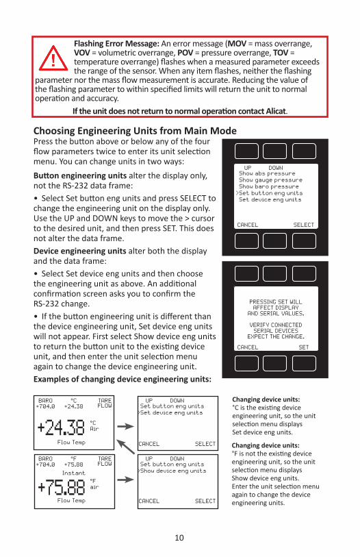
Flashing Error Message: An error message (MOV = mass overrange, VOV = volumetric overrange, POV = pressure overrange, TOV = temperature overrange) flashes when a measured parameter exceeds the range of the sensor. When any item flashes, neither the flashing
parameter nor the mass flow measurement is accurate. Reducing the value of the flashing parameter to within specified limits will return the unit to normal operation and accuracy.
If the unit does not return to normal operation contact Alicat.
Choosing Engineering Units from Main ModePress the button above or below any of the four flow parameters twice to enter its unit selection menu. You can change units in two ways:Button engineering units alter the display only, not the RS-232 data frame:• Select Set button eng units and press SELECT to change the engineering unit on the display only. Use the UP and DOWN keys to move the > cursor to the desired unit, and then press SET. This does not alter the data frame.Device engineering units alter both the display and the data frame:• Select Set device eng units and then choose the engineering unit as above. An additional confirmation screen asks you to confirm the RS-232 change.• If the button engineering unit is different than the device engineering unit, Set device eng units will not appear. First select Show device eng units to return the button unit to the existing device unit, and then enter the unit selection menu again to change the device engineering unit.Examples of changing device engineering units:
SETCANCEL
PRESSING SET WILLAFFECT DISPLAY
AND SERIAL VALUES.
VERIFY CONNECTEDSERIAL DEVICES
EXPECT THE CHANGE.
SELECTCANCEL
Show baro pressure
DOWNUP
Set button eng unitsSet device eng units
Show gauge pressureShow abs pressure
>
SELECTCANCEL
DOWNUP
Set device eng unitsSet button eng units
>
SELECTCANCEL
DOWNUP
Show device eng unitsSet button eng units
>
#CAir
Flow Temp
+24.38
TAREFLOW
#C+24.38
BARO+704.0
#Fair
Flow Temp+75.88
Instant
TAREFLOW
#F+75.88
BARO+704.0
Changing device units:°C is the existing device engineering unit, so the unit selection menu displays Set device eng units.
Changing device units:°F is not the existing device engineering unit, so the unit selection menu displays Show device eng units.Enter the unit selection menu again to change the device engineering units.

11
SELECT MENUFrom Select Menu you can change the selected gas, interact with your RS-232 settings or read manufacturer’s data.Press the button next to the desired operation to bring that function to the screen.
An explanation for each screen can be found on the following pages.
TARES
ADV SETUP
MAIN
ABOUT
#C+21.50
+0.00CCM MENU
TARE FLOW
SCCMAir
PSIA+13.60
+0.00SCCM
BASIC CONFIG
DEVICE STATE
BACK MAIN
MFG INFO
DEVICE INFO
COMMSETUP
BACK MAIN
SENSOR SETUP
DEVICEUNITS
BACK MAIN
STP/NTP
GASN2
BACK MAIN
TARE PRESS
TARE FLOW
DISP SETUP
ADVSETUP
TARESABOUT
MAINBASIC
CONFIG
Select Menu
+ 0.00

12
ABOUTPress DEVICE INFO to show important information about your flow device including the model number, serial number, and date of manufacture.
Press BACK to return to the About display.
Push MAIN to return to the Main display.
Manufacturer information is accessed by pressing the MFG INFO button on the About Menu display.
The initial display shows the name and telephone number of the manufacturer.
BACK MAIN
MODEL: M-100SCCM-DSERIAL NO: 100903DATE MFG: 03/17/2017DATE CAL: 03/17/2017CAL BY: DLSW REV: 7V01.0-R22
DEVICE STATE
BACK MAIN
MFGINFO
DEVICE INFO
DEVICE STATE: This diagnostic screen displays the current internal register values, which is useful for noting factory settings prior to making any changes. It is also helpful for troubleshooting with Alicat customer service personnel.Select the DEVICE STATE button from the ABOUT screen to view a list of select register values. Pressing the PAGE button will cycle the display through the register screens. An example screen is shown at left.
BACK MAIN
R8: AP Sig 7871R9: Temp Sig 39071R10: DP Sig 9986R11: DP Brdg 36673R13: AP Brdg 36673R16: Meter Func 199R18: Power Up 32768
PAGE
BACK MAIN
A L I C A T S C I E N T I F I Cw w w . a l i c a t . c o mPh 520-290-6060Fax 520-290-0109
DEVICE INFO MFG INFO
ABOUT
DEVICE STATE
13
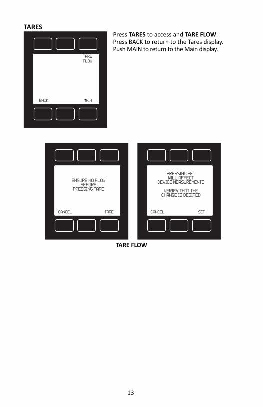
TARESPress TARES to access and TARE FLOW.Press BACK to return to the Tares display.Push MAIN to return to the Main display.
BACK MAIN
TAREFLOW
CANCEL TARE
ENSURE NO FLOWBEFORE
PRESSING TARE
CANCEL SET
PRESSING SET WILL AFFECT
DEVICE MEASUREMENTS
VERIFY THAT THE CHANGE IS DESIRED
TARE FLOW

14
BASIC CONFIGPress BASIC CONFIG to select gases, device units, and change STP and NTP references. Press BACK to return to the Select Menu display. Push MAIN to return to the Main display.Gas Select allows you to set your device to up to 150 gases and mixes. You can also use COMPOSER to program and store up to 20 gas mixes.Gas Select is accessed by pressing the button above GAS on the BASIC CONFIG display. To select a gas, use the UP and DOWN buttons to position the arrow in front of the desired gas category. » Recent: Eight most recent selections » Standard: Gases and mixes standard on
earlier Alicat instruments (page 26) » Factory Custom: Present only if customer
requested gases were added at the factory » COMPOSER User Mixes: Gas mixes
programmed by the user (page 15) » Bioreactor (page 30) » Breathing (page 31) » Chromatography (page 33) » Fuel (page 32) » Laser (page 32) » O2 Concentrator (page 33) » Pure Corrosive* (page 27) » Pure Non-Corrosive (page 26) » Refrigerant* (page 28) » Stack (page 33) » Welding (page 29)
Press PAGE to view a new page in the gas category list.Press SELECT to view the gases in the selected category. Align the arrow with the desired gas. Press SET to record your selection and return to the MAIN display. The selected gas will be displayed on the screen.
* Pure Corrosive and Refrigerant gases are only available on S-Series instruments that are compatible with these gases.Note: Gas Select may not be available on units ordered with a custom gas or blend.
See pages 26 -33 for a full list of gases in each category.
DEVICEUNITS
BACK MAIN
STP/NTP
GASN2
DOWN
BACK SELECT
PAGE
>Recent Standard Factory Custom COMPOSER User Mixes Bioreactor Breathing Chromatography Fuel
UP
DOWN
CANCEL SET
PAGE
> Fuel Laser O2 Concentrator Pure Corrosive Pure Non-Corrosive Refrigerant Stack Welding
UP

15
COMPOSERComposer allows you to program and save up to 20 custom gas mixes containing 2 to 5 component gases found in the gas lists (pages 32-39). The minimum resolution is 0.01%.
Composer is accessed by selecting COMPOSER User Mixes on the GAS SELECT display.
Press SET when the arrow is aligned with Add Mix.
Name the mix by pressing the UP and DOWN buttons for letters, numerals and symbols.
CHANGE CASE – Toggles the letter case. Letters remain in selected case until CHANGE CASE is pushed again.
Press SET to save the name.
After naming the mix, press ADD GAS and select the gas category and the component gas.
Select the digit with arrow and adjust the % with the UP and DOWN buttons. Press set to save. Add up to 4 more gases as needed. The total must equal 100% or an error message will appear.
GAS OPTNS allows you to adjust the percentage of the constituents or delete a gas from the mix. Gas mixes cannot be adjusted after they have been saved.
DOWN
CANCEL SET
>Add Mix: 20 FreeUP
DOWN
BACK/CANCEL
CHANGE CASE SET
NEXTLETTER
COMPOSER Mix name:
MyGas ------˄
UP
ADD GAS
BACK/CANCEL
CHANGE CASE SET
GAS OPTNS
COMPOSER Mix: MyGAS
0.00% of Total
EDIT NAME

16
Once the mix has been saved, you may press CREATE SIMILAR to compose an additional mix based on the mix you have just saved. This CREATE SIMILAR option is not available after leaving this screen.
Press CREATE NEW to add a completely new mix.
Press SELECT MIXTURE to bring the custom mix onto the MAIN display.
MAINSELECT MIXTURE
CREATE SIMILAR
COMPOSER USER MIXMyGas
HAS BEEN SAVED
CREATE NEW
DOWN
BACK/CANCEL CLEAR SET
SELECT DIGIT
Percent of Air:
50.00 ˄
UP DOWN
BACK/CANCEL CLEAR SET
SELECT DIGIT
Percent of Ar Argon:
30.00 ˄
UP
DOWN
BACK/CANCEL CLEAR SET
SELECT DIGIT
Percent of He Helium:
20.00 ˄
UP ADD GAS
CANCEL SAVE
GAS OPTNS
COMPOSER Mix: MyGAS 50% Air 30% AR Argon 20% He Helium 100.00% Total
EDIT NAME

17
DEVICE UNITSPress DEVICE UNITS to access menus of units of measure for each parameter (and totalizer if so equipped).Scroll to the desired unit and press select.Once selected, you will see the message shown below. Verify that all connected devices expect the change.See pages 34 and 35 for a full list of available units.
DOWN
BACK SELECT
Mass FlowVolumetric FlowPressureTemperatureMass TotalizerTotalizer Time
UP
DOWN
CANCEL SET
PAGE
SCCMScm3/hSm3/hSm3/dSin3/mSCFHNmL/s
UPPRESSING SET WILL
AFFECT DISPLAYAND SERIAL VALUES
VERIFY CONNECTED SERIAL DEVICES
EXPECT THE CHANGE
SETCANCEL
DEVICE UNITS
MASS FLOW UNITS

18
STP/NTPSTP/NTP allows selection of the temperature and pressure reference condition for mass flow. For standardardized flow (when using mass flow units that begin with S), Stan T and Stan P define the reference temperature and pressure. For normalized flow (when using mass flow units that begin with N), Norm T and Norm P define the reference temperature and pressure.This feature is generally useful for comparing to other devices or systems that may be at a different temperature or pressure standard. The same flow, when referenced to different
temperatures and/or pressures, will result in different reported values. Standardized and normalized flow references define the temperature and pressure conditions for which the flow is calculated; this allows flows measured under different conditions to be compared by calculating them using a common set of conditions.Use the UP/DOWN buttons to select a catagory from the displayed list as shown.Press CHANGE to access the parameter's display. Now use the SELECT DIGIT and UP/DOWN buttons to make your changes and press SET.Once a selection has been made and recorded using the SET button, a change acknowledgement message will be displayed on screen. Selecting "Ref temp units" or "Ref pressure units" will allow changing of the temperature or pressure unit for the reference.Press BACK to return to the BASIC CONFIG screen.
DOWN
BACK
Stan T: 25.00#CStan P: 14.700 PSIANorm T: 25.00#CNorm P: 14.70 PSIARef temp unitsRef pressure units
CHANGE
UP
Std P
14.69595
DOWN
BACK/CANCEL SET
UP SELECTDIGIT
Ref Pressure: PSIA
CLEAR
Std T
CLEAR
DOWN
BACK/CANCEL
Ref Temperature: #C
SET
UP SELECTDIGIT
25.0000
CLEAR

19
ADV SETUPPress ADV SETUP to adjust the sensor settings, unit ID, baud rate, or display settings. Press BACK to return to the Select Menu display. Push MAIN to return to the Main display.SENSOR SETUPZERO BAND refers to Display Zero Deadband. Zero deadband is a value below which the display jumps to zero. This deadband is often desired to prevent electrical noise from showing up on the display as minor flows or pressures that do not exist. Display Zero Deadband does not affect the analog or digital signal outputs.ZERO BAND can be adjusted between 0 and 6.3% of the sensor’s Full Scale (FS). Press ZERO BAND. Then use SELECT to choose the digit with the arrow and the UP/DOWN buttons to change the value. Press SET to record your value. Press CLEAR to return to zero.Pressure Averaging and Flow Averaging may be useful to make it easier to read and interpret rapidly fluctuating pressures and flows. Pressure and flow averaging can be adjusted between 1 (no averaging) and 255 (maximum averaging). These are geometric running averages where the number between 1 and 255 can be considered roughly equivalent to the response time constant in milliseconds. This can be effective at “smoothing” high frequency process oscillations such as those caused by diaphragm pumps. Press PRESS AVG. Then use SELECT to choose the digit with the arrow and the UP and DOWN buttons to change the value. Press SET to record your value. Press CLEAR to return to zero.Press FLOW AVG. Then use SELECT to choose the digit with the arrow and the UP and DOWN buttons to change the value. Press SET to record your value. Press CLEAR to return to zero.Setting a higher number will equal a smoother display.
ZERO BAND
CLEAR
DOWN
BACK/CANCEL
Zero: % Of Full Scale
SET
UP SELECTDIGIT
0.0
CLEAR
PRESS AVG
BACK MAIN
FLOW AVG
ZERO BAND
SENSOR SETUP
COMM SETUP
BACK MAIN
DISP SETUP
SENSOR SETUP
ADV SETUP

20
COMM SETUPPress COMM SETUP to adjust the unit ID or baud rate.
UNIT ID – Valid unit identifiers are the letters A-Z and @. The identifier allows you to assign a unique address to each device so that multiple units can be connected to a single RS-232 computer port. Press UNIT ID. Use the UP and DOWN buttons to change the Unit ID. Press SET to record the ID. Press Reset to return to the previously recorded Unit ID. Any Unit ID change will take effect when SET is pressed.If the symbol @ is selected as the Unit ID, the device will enter streaming mode when SET is pressed. See RS-232 Communications (page 23) for
information about the streaming mode.BAUD – Both this instrument and your computer must send/receive data at the same baud rate. The default baud rate for this device is 19200 baud. Press BAUD. Use the UP and DOWN buttons to select the baud rate that matches your computer. The choices are 57600, 38400, 19200, 9600, or 2400 baud. Press SET to record the baud rate. Any baud rate change will take effect when SET is pressed..
PRESS AVG
CLEAR
DOWN
BACK/CANCEL
Avg Time Const: msec
SET
UP SELECTDIGIT
001
CLEAR
FLOW AVG
CLEAR
DOWN
BACK/CANCEL
Avg Time Const: msec
SET
UP SELECTDIGIT
127
CLEAR
DOWN
BACK SET
BAUD UP
19200
BACK MAIN
UNIT IDA
BAUD19200
UP
BACK RESET A SET
UNIT IDC
DOWN
C
COMM SETUP
BAUDUNIT ID
Comm:RS232Serial

21
DISP SETUPPress DISP SETUP to adjust the LCD contrast or rotate the display.
LCD CONTRAST: The display contrast can be adjusted between 0 and 28, with zero being the lightest and 31 being the darkest. Use the UP and DOWN buttons to adjust the contrast. Press SET when you are satisfied. Press BACK to return to DISP SETUP. Press RESET to revert to the default contrast level (10)ROTATE DISP: Press ROTATE DISP and select Inverted 180° if your device is inverted. The display and buttons will rotate together.
BACK MAIN
LCD CONTRAST
ROTATE DISP
DISP SETUP
LCD CONTRAST
DOWN
BACK/CANCEL RESET SET
UP
11LCD Contrast
DOWN
CANCEL
Defualt - 0#Inverted - 180#
SET
UP
ROTATE DISPLAY

22
RS-232 Output and Input
Connect the male RS-232 DB9 port of the PCU to the serial port of your computer or data logger. This will normally require a female/female DB9 cable (included).
Alicat’s Flow Vision Software
Flow Vision is an affordable software program that interfaces with RS-232 and is compatible with most Alicat flow and pressure instruments. The graphical user interface (GUI) provides automatic configuration, session saving for easy configuration and experiment setup reloads, data capturing and logging (including a graphing tool), simple script building for automating meter and control command sequences, software alarms, and support for multiple devices.
Flow Vision SC™ is for general use with up to 26 different Alicat devices, while Flow Vision MX™ is specifically designed for gas mixing applications.
Alicat’s Free Serial Terminal Application
Serial Terminal was written by Alicat as a preconfigured program for RS-232 communication with Alicat devices and can be downloaded from www.alicat.com/support/software-drivers. Serial Terminal requires a Microsoft® .Net Framework to run properly which is usually preinstalled on the PC.
Once downloaded, simply run SerialTerminal.exe and enter the COM port number and baud rate of your Alicat device as prompted. The COM port number may be determined using the Device Manager on the computer, and the default baud rate of an Alicat device is 19200.
Additional Programs that are compatible with Alicat products
Alicat products are compatible with many serial communication type software packages including PuTTy and LabVIEW. A brief set of instructions for each of these programs is available at www.alicat.com/support/software-drivers.
Many other programs are also compatible with Alicat devices. To set up serial communication it is important to note which COM port the Alicat is connected to and the communication settings required. The default communication settings are as follows: baud rate = 19200, data bits = 8, stop bits = 1, parity = none, and flow control = none. Not all programs have these options and care should be taken to determine the proper communication setup with the desired program.
Alicat has written drivers specifically for LabVIEW which are available for download at www.alicat.com/support/software-drivers.

23
Sending a Command
In this section, a command will be denoted with a different font. For example, command<CR> . <CR> will be used to symbolize a carriage return. How a carriage return is entered is dependent on the serial communication program being used. With Serial Terminal, this can commonly be accomplished by pressing “Enter” or “Return”.
Parenthesis denote a value that must be filled in by the user. For example,(unit ID)<CR> should be changed to A<CR> when using a device with Unit ID “A”. It may also be useful to note that commands are case insensitive. For example, A<CR> is equivalent to a<CR>.
Polling Mode
All Alicat devices are sent in Polling Mode with Unit ID A unless otherwise requested. Polling a device will return a data frame of the current measurements in the device in units shown on the display. See Data Format, later in this section, for more information. Each unit may be polled individually using the command (unit ID)<CR>.
A device’s Unit ID may be changed using the command (current unit ID)@=(desired unit ID)<CR>. The Unit ID can also be changed via the front panel using the RS-232 communication select menu.
Care should be taken not to assign the same unit ID to more than one device on a single COM port. Up to 26 units may be connected simultaneously as Unit IDs between A and Z are allowed.
Streaming Mode
In Streaming Mode, a device will automatically output the data stream at a pre-determined rate. The default rate is set to 50 ms and can be changed via register values for units with software version 4v30 or newer. Only one unit on a given COM port may be in streaming mode at a time.
To change a unit from Polling Mode to Streaming Mode, type (unit ID)@=@<CR>. This is equivalent to changing the unit ID to “@”. If data does not appear, check all the connections and COM port settings.
When sending a command to a unit in streaming mode, the flow of information will not stop while the user is typing; and the typed text may not be readable depending on the terminal settings.
If the unit does not receive a valid command, it will ignore it. If in doubt, simply perform another carriage return and start again.
To change a unit from Streaming Mode to Polling Mode, type @@=(unit ID)<CR>. If entered correctly, the data stream will stop and the device will now be in polling mode.
Communication Set Uphttp://www.alicat.com/support/instructional-videos/

24
Data Format
The data frame on the screen represents the current measurements in the device in the units shown on the display. By default, mass flow meters are configured to output six columns of data.
All data is displayed in the “device units” selected on the unit. Devices come standard with units of PSIA, °C, and either SLPM/LPM or SCCM/CCM, depending on the flow range of the device.
Note that the “button units” available on portable units will not affect the serial output. The first column is the unit ID. This column will be excluded if the device is in streaming mode. The next columns are absolute pressure, temperature, volumetric flow rate, mass flow rate, and selected gas, respectively.
For example, suppose a meter with unit ID A was ordered with units of SCFM or the “device units” are currently selected as SCFM. If air is selected, at atmospheric temperature, the data frame may read:
A +014.70 +025.00 +02.004 +02.004 AirUnit ID Pressure Temp Vol. Flow Mass Flow Gas
M-Series Mass Flow Meter Data Format
On units with the totalizer function, the totalized flow will be displayed in column six, with the selected gas moving to column seven. Additional columns, including status codes, may be present to the right of the gas selection column.
Changing the gas selection using Gas Select via RS-232
To change the selected gas, type (unit ID)G(gas number)<CR>. For a complete list of gas numbers available on the device, see “Gas Lists with Viscosities, Densities and Compressibilities” in this manual.
This list is also available on the gas select menu on the unit. For example, Helium has a gas number of 7. To change the selected gas on unit “A” to Helium, type AG7<CR>. On devices with GP software, use the command (unit ID)$$G(gas number)<CR> instead.
Additional Serial Commands
For more advanced serial communication commands, please contact Alicat or view the User’s Guide to Advanced Serial Programming at Alicat.com/knowledge/documents-resources

25
Operating Principle
All M-Series Gas Flow Meters (and MC Series Gas Flow Controllers) are based on the accurate measurement of volumetric flow. The volumetric flow rate is determined by creating a pressure drop across a unique internal restriction, known as a Laminar Flow Element (LFE), and measuring differential pressure across it. The restriction is designed so that the gas molecules are forced to move in parallel paths along the entire length of the passage; hence laminar (streamline) flow is established for the entire range of operation of the device. Unlike other flow measuring devices, in laminar flow meters the relationship between pressure drop and flow is linear.
Please visit the Alicat web site for a detailed explanation this principle.http://www.alicat.com/technical-information/theory-of-operation/
STANDARD GAS DATA TABLES: Those of you who have older Alicat products may notice small discrepancies between the gas property tables of your old and new units. Alicat Scientific, Inc. has incorporated the latest data sets from NIST (including their REFPROP 9 data where available) in our products’ built-in gas property models. Be aware that the calibrators that you may be using may be checking against older data sets such as the widely distributed Air Liquide data. This may generate apparent calibration discrepancies of up to 0.6% of reading on well behaved gases and as much as 3% of reading on some gases such as propane and butane, unless the standard was directly calibrated on the gas in question. As the older standards are phased out, this difference in readings will cease to be a problem. If you see a difference between the Alicat meter and your in-house standard, in addition to calling Alicat Scientific at (520) 290-6060, call the manufacturer of your standard for clarification as to which data set they used in their calibration. This comparison will in all likelihood resolve the problem.

26
PURE
NO
N-C
ORR
OSI
VE
GA
SES
25°C
0°C
Gas
N
umbe
rSh
ort
Nam
eLo
ng N
ame
Abso
lute
Vi
scos
ityD
ensit
y 14
.696
PSI
ACo
mpr
essib
ilty
14.6
96 P
SIA
Abso
lute
Vi
scos
ity
Den
sity
14.6
96
PSIA
Com
pres
sibilt
y 14
.696
PSI
A
14C2
H2
Acet
ylen
e10
4.44
800
1.07
200
0.99
2800
097
.374
1.17
280.
9905
0A
irA
ir18
4.89
890
1.18
402
0.99
9696
717
2.57
41.
2930
0.99
941
Ar
Arg
on22
6.23
990
1.63
387
0.99
9365
621
0.16
71.
7840
0.99
9116
i-C4H
10i-B
utan
e74
.978
462.
4402
80.
9735
331
68.7
592.
6887
0.96
4513
n-C4
H10
n-Bu
tane
74.0
5358
2.44
930
0.96
9949
367
.690
2.70
370.
9591
4CO
2Ca
rbon
Dio
xide
149.
3184
01.
8079
80.
9949
545
137.
107
1.97
680.
9933
3CO
Carb
on M
onox
ide
176.
4933
01.
1453
00.
9996
406
165.
151
1.25
050.
9993
60D
2D
eute
rium
126.
5983
60.
1645
51.
0005
970
119.
196
0.17
961.
0006
5C2
H6
Etha
ne93
.541
171.
2384
60.
9923
987
86.1
291.
3550
0.99
0115
C2H
4Et
hyle
ne (E
then
e)10
3.18
390
1.15
329
0.99
4255
094
.697
1.26
110.
9925
7H
e H
eliu
m19
8.45
610
0.16
353
1.00
0472
018
6.94
50.
1785
1.00
056
H2
Hyd
roge
n89
.153
550.
0823
51.
0005
940
83.9
690.
0899
1.00
0617
KrKr
ypto
n25
1.32
490
3.43
229
0.99
7926
623
2.19
33.
7490
0.99
722
CH4
Met
hane
110.
7595
00.
6568
80.
9982
472
102.
550
0.71
750.
9976
10N
eN
eon
311.
1264
00.
8244
21.
0004
810
293.
822
0.89
991.
0005
8N
2N
itrog
en17
8.04
740
1.14
525
0.99
9801
616
6.28
71.
2504
0.99
959
N2O
Nitr
ous
Oxi
de14
8.41
240
1.80
888
0.99
4532
713
6.31
01.
9779
0.99
2811
O2
Oxy
gen
205.
5021
01.
3087
90.
9993
530
191.
433
1.42
900.
9990
12C3
H8
Prop
ane
81.4
6309
1.83
204
0.98
3805
474
.692
2.01
050.
9785
19SF
6Su
lfur H
exafl
uorid
e15
3.53
200
6.03
832
0.98
8668
114
0.89
06.
6162
0.98
4918
XeXe
non
229.
8483
05.
3950
20.
9947
117
212.
157
5.89
800.
9932
GA
S SE
LECT
> S
tand
ard:
M
Met
ers
will
dis
play
: Ace
tyle
ne, A
ir, A
rgon
, But
ane,
Car
bon
Dio
xide
, Car
bon
Mon
oxid
e, E
than
e, E
thyl
ene
(Eth
ene)
, Hel
ium
, Hyd
roge
n,
Iso-
Buta
ne, K
rypt
on, M
etha
ne, N
eon,
Nitr
ogen
, Nitr
ous
Oxi
de, O
xyge
n, P
ropa
ne, S
ulfu
r Hex
afluo
ride,
Xen
on, A
-25,
A-7
5, A
1025
, C-2
, C-8
, C-1
0,
C-25
, C-7
5, P
-5, S
tar2
9.
MS
Met
ers
add
the
follo
win
g: A
mm
onia
, Chl
orin
e G
as, H
ydro
gen
Sulfi
de, N
itric
Oxi
de, N
itrog
en T
riflou
ride,
Pro
pyle
ne,
Sulfu
r Dio
xide
, and
N
itrog
en D
ioxi
de to
0.5
% in
an
iner
t car
rier,
Refr
iger
ant g
ases
.

27
PURE
CO
RRO
SIV
ES*
25°C
0°C
Gas
N
umbe
rSh
ort
Nam
eLo
ng N
ame
Abso
lute
Vi
scos
ityD
ensit
y 14
.696
PSI
ACo
mpr
essib
ilty
14.6
96 P
SIA
Abso
lute
Vi
scos
ityD
ensit
y 14
.696
PSI
ACo
mpr
essib
ilty
14.6
96 P
SIA
32N
H3
Am
mon
ia10
0.92
580
0.70
352
0.98
9455
591
.930
0.77
150.
9848
612
801B
uten
eBu
tyle
ne (1
-But
ene)
81.6
2541
2.35
906
0.97
2125
174
.354
2.60
360.
9614
456
81cB
uten
eCi
s-Bu
tene
(c
is-2
-but
ene)
79.9
6139
2.36
608
0.96
9240
5Li
quid
Liqu
idLi
quid
82iB
uten
eIs
o-Bu
tene
80.8
4175
2.35
897
0.97
2162
673
.640
2.60
380.
9613
501
83tB
uten
eTr
ans-
Bute
ne80
.280
182.
3659
60.
9692
902
Liqu
idLi
quid
Liqu
id84
COS
Carb
onyl
Sul
fide
124.
0960
02.
4832
20.
9888
443
113.
127
2.72
020.
9853
2833
Cl2
Chlo
rine
134.
5660
02.
9350
60.
9874
470
125.
464
3.16
350.
9840
785
CH3O
CH3
Dim
ethy
leth
er
90.9
9451
1.91
822
0.98
1645
382
.865
2.10
900.
9745
473
34H
2SH
ydro
gen
Sulfi
de (H
2S)
123.
8689
01.
4037
60.
9923
556
112.
982
1.53
610.
9898
858
31N
F3N
F3 (N
itrog
en T
rifluo
ride)
175.
4250
02.
9133
90.
9963
859
162.
426
3.18
400.
9951
506
30N
ON
O (N
itric
Oxi
de)
190.
0595
01.
2267
20.
9997
970
176.
754
1.33
940.
9995
317
36C3
H6
Prop
ylen
e (P
ropy
lene
)85
.598
951.
7450
90.
9856
064
78.1
291.
9139
0.98
0937
386
SiH
4Si
lane
(SiH
4)11
5.94
400
1.32
003
0.99
4500
010
7.05
31.
4433
0.99
282
35SO
2Su
lfur D
ioxi
de12
7.83
100
2.66
427
0.98
2840
711
6.71
72.
9312
0.97
5086
6*P
ure
Corr
osiv
e ga
ses
are
only
ava
ilabl
e on
S-S
erie
s in
stru
men
ts th
at a
re c
ompa
tible
with
thes
e ga
ses.
Gas
num
bers
33
and
35 a
re n
ot
avai
labl
e on
con
trol
lers
.

28
REFR
IGER
AN
TS25
°C0°
CG
as
Num
ber
Shor
t N
ame
Long
Nam
eAb
solu
te
Visc
osity
Den
sity
14.6
96 P
SIA
Com
pres
sibilt
y 14
.696
PSI
AAb
solu
te
Visc
osity
Den
sity
14.6
96 P
SIA
Com
pres
sibilt
y 14
.696
PSI
A10
0R-
11Tr
ichl
orofl
uoro
met
hane
101.
6048
05.
8235
80.
9641
448
Liqu
idLi
quid
Liqu
id10
1R-
115
Chlo
rope
ntafl
uoro
etha
ne12
5.14
780
6.43
293
0.98
1462
811
4.89
17.
0666
0.97
5228
710
2R-
116
Hex
afluo
roet
hane
137.
8173
05.
7009
70.
9895
011
126.
635
6.24
580.
9858
448
103
R-12
4Ch
loro
tetr
afluo
roet
hane
115.
9311
05.
7282
10.
9738
286
105.
808
6.31
750.
9638
0710
4R-
125
Pent
afluo
roet
hane
129.
6174
04.
9816
90.
9847
599
118.
793
5.46
890.
9791
3710
5R-
134A
Tetr
afluo
roet
hane
118.
1882
04.
2578
40.
9794
810
108.
311
4.68
630.
9713
825
106
R-14
Tetr
afluo
rom
etha
ne17
2.44
680
3.61
084
0.99
6255
315
9.68
83.
9467
0.99
4896
410
7R-
142b
Chlo
rodi
fluor
oeth
ane
104.
2019
04.
2163
20.
9742
264
95.0
924.
6509
0.96
4037
110
8R-
143a
Trifl
uoro
etha
ne11
0.86
600
3.49
451
0.98
3001
110
1.34
43.
8394
0.97
6575
510
9R-
152a
Difl
uoro
etha
ne10
0.81
320
2.75
903
0.97
8524
591
.952
3.03
770.
9701
025
110
R-22
Difl
uoro
mon
ochl
orom
etha
ne12
6.30
390
3.58
679
0.98
5364
111
5.32
53.
9360
0.98
0112
811
1R-
23Tr
ifluo
rom
etha
ne14
9.13
160
2.88
404
0.99
2273
413
6.99
73.
1568
0.98
9520
411
2R-
32D
ifluo
rom
etha
ne12
6.13
140
2.15
314
0.98
7596
011
5.30
32.
3619
0.98
2716
111
3RC
-318
Oct
afluo
rocy
clob
utan
e11
5.04
690
8.42
917
0.97
0015
610
4.78
59.
3017
0.95
9473
811
4R-
404A
44%
R-1
25 /
4% R
-134
A / 5
2% R
-143
A12
0.30
982
4.18
002
0.98
3634
211
1.58
44.
5932
0.97
7088
911
5R-
407C
23%
R-3
2 / 2
5% R
-125
/ 52
% R
-134
A12
3.55
369
3.95
268
0.98
2667
211
2.69
84.
3427
0.97
6284
911
6R-
410A
50%
R-3
2 / 5
0% R
-125
130.
2438
43.
5653
80.
9861
780
122.
417
3.91
180.
9811
061
117
R-50
7A50
% R
-125
/ 50
% R
-143
A12
1.18
202
4.23
876
0.98
3880
511
2.44
54.
6573
0.97
7420
7*R
efri
gera
nt g
ases
are
onl
y av
aila
ble
on S
-Ser
ies
inst
rum
ents
that
are
com
patib
le w
ith th
ese
gase
s.

29
WEL
DIN
G G
ASE
S25
°C0°
CG
as
Num
ber
Shor
t N
ame
Long
Nam
eAb
solu
te
Visc
osity
Den
sity
14.6
96 P
SIA
Com
pres
sibilt
y 14
.696
PSI
AAb
solu
te
Visc
osity
Den
sity
14.6
96 P
SIA
Com
pres
sibilt
y 14
.696
PSI
A23
C-2
2% C
O2
/ 98%
Ar
224.
7148
01.
6372
70.
9993
165
208.
673
1.78
770.
9989
9322
C-8
8% C
O2
/ 92%
Ar
220.
1352
01.
6474
90.
9991
624
204.
199
1.79
890.
9987
964
21C-
1010
% C
O2
/ 90%
Ar
218.
6026
01.
6509
10.
9991
086
202.
706
1.80
270.
9987
278
140
C-15
15%
CO
2 / 8
5% A
r21
4.74
960
1.65
945
0.99
8968
719
8.96
01.
8121
0.99
8549
314
1C-
2020
% C
O2
/ 80%
Ar
210.
8696
01.
6680
00.
9988
210
195.
198
1.82
150.
9983
605
20C-
2525
% C
O2
/ 75%
Ar
206.
9763
01.
6765
80.
9986
652
191.
436
1.83
090.
9981
609
142
C-50
50%
CO
2 / 5
0% A
r18
7.53
160
1.71
972
0.99
7748
417
2.84
31.
8786
0.99
6977
724
C-75
75%
CO
2 / 2
5% A
r16
8.22
500
1.76
344
0.99
6548
415
4.67
01.
9271
0.99
5401
25H
e-25
25%
He
/ 75%
Ar
231.
6056
31.
2659
80.
9996
422
216.
008
1.38
140.
9999
341
143
He-
5050
% H
e / 5
0% A
r23
6.15
149
0.89
829
0.99
9918
822
0.46
40.
9800
1.00
039
26H
e-75
75%
He
/ 25%
Ar
234.
6860
10.
5308
11.
0001
954
216.
937
0.57
921.
0005
7114
4H
e-90
90%
He
/ 10%
Ar
222.
1456
60.
3104
11.
0003
614
205.
813
0.33
881.
0005
727
A10
2590
% H
e / 7.
5% A
r / 2.
5% C
O2
214.
9760
80.
3146
01.
0002
511
201.
175
0.34
331.
0005
56
28St
ar29
Star
gon
CS 9
0% A
r /
8% C
O2
/ 2%
O2
219.
7934
01.
6409
90.
9991
638
203.
890
1.79
180.
9987
98

30
BIO
REA
CTO
R G
ASE
S25
°C0°
CG
as
Num
ber
Shor
t N
ame
Long
Nam
eAb
solu
te
Visc
osity
Den
sity
14.6
96 P
SIA
Com
pres
sibilt
y 14
.696
PSI
AAb
solu
te
Visc
osity
Den
sity
14.6
96 P
SIA
Com
pres
sibilt
y 14
.696
PSI
A14
5Bi
o-5M
5% C
H4
/ 95%
CO
214
8.46
635
1.75
026
0.99
5119
113
6.26
81.
9134
0.99
3581
614
6Bi
o-10
M10
% C
H4
/ 90%
CO
214
7.54
809
1.69
254
0.99
5283
813
5.38
31.
8500
0.99
3893
147
Bio-
15M
15%
CH
4 / 8
5% C
O2
146.
5585
91.
6348
40.
9954
484
134.
447
1.78
670.
9941
932
148
Bio-
20M
20%
CH
4 / 8
0% C
O2
145.
4923
81.
5771
60.
9956
130
133.
457
1.72
350.
9944
8214
9Bi
o-25
M25
% C
H4
/ 75%
CO
214
4.34
349
1.51
950
0.99
5777
713
2.40
71.
6603
0.99
4759
415
0Bi
o-30
M30
% C
H4
/ 70%
CO
214
3.10
541
1.46
186
0.99
5942
313
1.29
01.
5971
0.99
5025
515
1Bi
o-35
M35
% C
H4
/ 65%
CO
214
1.77
101
1.40
424
0.99
6106
913
0.10
21.
5340
0.99
5280
315
2Bi
o-40
M40
% C
H4
/ 60%
CO
214
0.33
250
1.34
664
0.99
6271
612
8.83
41.
4710
0.99
5523
915
3Bi
o-45
M45
% C
H4
/ 55%
CO
213
8.78
134
1.28
905
0.99
6436
212
7.47
81.
4080
0.99
5756
415
4Bi
o-50
M50
% C
H4
/ 50%
CO
213
7.10
815
1.23
149
0.99
6600
912
6.02
51.
3450
0.99
5977
915
5Bi
o-55
M55
% C
H4
/ 45%
CO
213
5.30
261
1.17
394
0.99
6765
512
4.46
21.
2821
0.99
6188
615
6Bi
o-60
M60
% C
H4
/40%
CO
213
3.35
338
1.11
642
0.99
6930
112
2.77
91.
2193
0.99
6388
515
7Bi
o-65
M65
% C
H4
/35%
CO
213
1.24
791
1.05
891
0.99
7094
812
0.95
91.
1564
0.99
6577
915
8Bi
o-70
M70
% C
H4
/ 30%
CO
212
8.97
238
1.00
142
0.99
7259
411
8.98
71.
0936
0.99
6756
715
9Bi
o-75
M75
% C
H4
/ 25%
CO
212
6.51
146
0.94
395
0.99
7424
011
6.84
21.
0309
0.99
6925
116
0Bi
o-80
M80
% C
H4
/ 20%
CO
212
3.84
817
0.88
650
0.99
7588
711
4.50
10.
9681
0.99
7083
216
1Bi
o-85
M85
% C
H4
/ 15%
CO
212
0.96
360
0.82
907
0.99
7753
311
1.93
80.
9054
0.99
7230
916
2Bi
o-90
M90
% C
H4
/ 10%
CO
211
7.83
674
0.77
166
0.99
7917
910
9.11
90.
8427
0.99
7368
416
3Bi
o-95
M95
% C
H4
/ 5%
CO
211
4.44
413
0.71
426
0.99
8082
610
6.00
50.
7801
0.99
7495
7

31
BREA
THIN
G G
ASE
S25
°C0°
CG
as
Num
ber
Shor
t N
ame
Long
Nam
eAb
solu
te
Visc
osity
Den
sity
14.6
96 P
SIA
Com
pres
sibilt
y 14
.696
PSI
AAb
solu
te
Visc
osity
Den
sity
14.6
96 P
SIA
Com
pres
sibilt
y 14
.696
PSI
A16
4EA
N-3
232
% O
2 / 6
8% N
218
6.86
315
1.19
757
0.99
9658
017
4.92
51.
3075
0.99
9371
516
5EA
N36
% O
2 / 6
4% N
218
7.96
313
1.20
411
0.99
9640
117
5.96
31.
3147
0.99
9350
816
6EA
N-4
040
% O
2 / 6
0% N
218
9.06
268
1.21
065
0.99
9622
217
6.99
31.
3218
0.99
9330
216
7H
eOx-
2020
% O
2 / 8
0% H
e21
7.88
794
0.39
237
1.00
0248
220
4.17
50.
4281
1.00
0593
168
HeO
x-21
21%
O2
/ 79%
He
218.
1598
40.
4038
21.
0002
370
204.
395
0.44
061.
0005
9116
9H
eOx-
3030
% O
2 / 7
0% H
e21
9.24
536
0.50
683
1.00
0136
320
5.14
00.
5530
1.00
0565
170
HeO
x-40
40%
O2
/ 60%
He
218.
5991
30.
6213
21.
0000
244
204.
307
0.67
791.
0005
0217
1H
eOx-
5050
% O
2 / 5
0% H
e21
6.95
310
0.73
583
0.99
9912
520
2.59
20.
8028
1.00
0401
172
HeO
x-60
60%
O2
/ 40%
He
214.
8262
60.
8503
70.
9998
006
200.
467
0.92
781.
0002
5717
3H
eOx-
8080
% O
2 / 2
0% H
e21
0.11
726
1.07
952
0.99
9576
819
5.87
21.
1781
0.99
9801
917
4H
eOx-
9999
% O
2 / 1
% H
e20
5.72
469
1.29
731
0.99
9364
219
1.64
61.
4165
0.99
9079
617
5EA
-40
Enric
hed
Air-4
0% O
218
9.42
518
1.21
429
0.99
9617
717
7.39
61.
3258
0.99
9326
117
6EA
-60
Enric
hed
Air-6
0% O
219
4.79
159
1.24
578
0.99
9529
518
2.26
11.
3602
0.99
9226
617
7EA
-80
Enric
hed
Air-8
0% O
220
0.15
060
1.27
727
0.99
9441
218
6.93
71.
3946
0.99
9128
8
178
Met
abol
Met
abol
ic E
xhal
ant (
16%
O2
/ 78
.04%
N2
/ 5%
CO
2 / 0
.96%
Ar)
180.
9593
61.
2090
90.
9994
833
170.
051
1.32
000.
9992
587

32
FUEL
GA
SES
25°C
0°C
Gas
N
umbe
rSh
ort
Nam
eLo
ng N
ame
Abso
lute
Vi
scos
ityD
ensit
y 14
.696
PSI
ACo
mpr
essib
ilty
14.6
96 P
SIA
Abso
lute
Vi
scos
ityD
ensit
y 14
.696
PSI
ACo
mpr
essib
ilty
14.6
96 P
SIA
185
Syn
Gas
-140
% H
2 +
29%
CO
+ 2
0% C
O2
+ 11
% C
H4
155.
6474
40.
7977
40.
9989
315
144.
565
0.87
040.
9992
763
186
Syn
Gas
-264
% H
2 +
28%
CO
+ 1
% C
O2
+ 7%
CH
415
1.98
915
0.43
715
1.00
0106
414
2.24
90.
4771
1.00
0263
187
Syn
Gas
-370
% H
2 +
4% C
O +
25%
CO
2 +
1% C
H4
147.
3368
60.
5602
40.
9991
225
136.
493
0.61
110.
9997
559
188
Syn
Gas
-483
% H
2 + 14
% CO
+ 3%
CH4
133.
6368
20.
2482
51.
0003
901
125.
388
0.27
091.
0005
0918
9N
at G
as-1
93%
CH4
/ 3%
C2H
6 / 1%
C3H
8 / 2%
N2 /
1% C
O2
111.
7702
70.
7070
90.
9979
255
103.
189
0.77
220.
9973
965
190
Nat
Gas
-295
% C
H4
/ 3%
C2H
6 / 1
% N
2 / 1
% C
O2
111.
5557
00.
6906
10.
9980
544
103.
027
0.75
430.
9974
642
191
Nat
Gas
-395
.2%
CH
4 / 2
.5%
C2H
6 / 0
.2%
C3H
8 / 0
.1%
C4
H10
/ 1.
3% N
2 / 0
.7%
CO
211
1.49
608
0.68
980
0.99
8041
010
2.98
00.
7534
0.99
7472
5
192
Coal
Gas
50%
H2
/ 35%
CH
4 / 1
0% C
O /
5% C
2H4
123.
6851
70.
4428
10.
9993
603
115.
045
0.65
890.
9963
8719
3En
do75
% H
2 +
25%
N2
141.
7210
00.
3478
71.
0005
210
133.
088
0.37
971.
0005
1119
4H
HO
66.6
7% H
2 / 3
3.33
% O
218
0.46
190
0.49
078
1.00
0180
416
8.66
40.
5356
1.00
0396
195
HD
-5LP
G
96.1
% C
3H8
/ 1.5
% C
2H6
/ 0.4
%
C3H
6 / 1
.9%
n-C
4H10
81.4
5829
1.83
428
0.98
3678
174
.933
2.01
280.
9784
565
196
HD
-10
LPG
85%
C3H
8 /
10%
C3H
6 / 5
% n
-C4H
1081
.419
971.
8537
80.
9832
927
74.9
342.
0343
0.97
8049
9
LASE
R G
ASE
S25
°C0°
CG
as
Num
ber
Shor
t N
ame
Long
Nam
eAb
solu
te
Visc
osity
Den
sity
14.6
96 P
SIA
Com
pres
sibilt
y 14
.696
PSI
AAb
solu
te
Visc
osity
Den
sity
14.6
96 P
SIA
Com
pres
sibilt
y 14
.696
PSI
A17
9LG
-4.5
4.5%
CO
2 / 1
3.5%
N2
/ 82%
He
199.
2430
00.
3696
31.
0001
332
187.
438
0.40
331.
0005
5118
0LG
-66%
CO
2 / 1
4% N
2 / 8
0% H
e19
7.87
765
0.39
910
1.00
0047
118
6.67
00.
4354
1.00
053
181
LG-7
7% C
O2
/ 14%
N2
/ 79%
He
197.
0051
90.
4154
80.
9999
919
186.
204
0.45
331.
0005
1418
2LG
-99%
CO
2 / 1
5% N
2 / 7
6% H
e19
5.06
655
0.45
805
0.99
9874
918
4.83
50.
4997
1.00
0478
183
HeN
e-9
9% N
e / 9
1% H
e22
4.68
017
0.22
301
1.00
0472
821
1.75
60.
2276
1.00
0516
184
LG-9
.49.
4% C
O2
/ 19.
25%
N2
/ 71.
35%
He
193.
7831
10.
5063
30.
9998
243
183.
261
0.55
231.
0004
58

33
O2
CON
CEN
TRAT
OR
GA
SES
25°C
0°C
Gas
N
umbe
rSh
ort
Nam
eLo
ng N
ame
Abso
lute
Vi
scos
ityD
ensit
y 14
.696
PSI
ACo
mpr
essib
ilty
14.6
96 P
SIA
Abso
lute
Vi
scos
ityD
ensit
y 14
.696
PSI
ACo
mpr
essib
ilty
14.6
96 P
SIA
197
OCG
-89
89%
O2
/ 7%
N2
/ 4%
Ar
204.
5331
31.
3103
30.
9993
849
190.
897
1.43
070.
9990
695
198
OCG
-93
93%
O2
/ 3%
N2
/ 4%
Ar
205.
6211
41.
3168
70.
9993
670
191.
795
1.43
790.
9990
499
199
OCG
-95
95%
O2
/ 1%
N2
/ 4%
Ar
206.
1649
71.
3201
40.
9993
580
192.
241
1.44
140.
9990
4
STA
CK G
ASE
S25
°C0°
CG
as
Num
ber
Shor
t N
ame
Long
Nam
eAb
solu
te
Visc
osity
Den
sity
14.6
96 P
SIA
Com
pres
sibilt
y 14
.696
PSI
AAb
solu
te
Visc
osity
Den
sity
14.6
96 P
SIA
Com
pres
sibilt
y 14
.696
PSI
A20
0FG
-12.
5% O
2 / 1
0.8%
CO
2 / 8
5.7%
N2
/ 1%
Ar
175.
2257
51.
2255
00.
9992
625
165.
222
1.33
790.
9990
842
201
FG-2
2.9%
O2
/ 14%
CO
2 / 8
2.1%
N2
/ 1%
Ar
174.
1800
21.
2472
90.
9991
056
164.
501
1.36
170.
9989
417
202
FG-3
3.7%
O2
/ 15%
CO
2 / 8
0.3%
N2
/ 1%
Ar
174.
0284
01.
2552
00.
9990
536
164.
426
1.37
030.
9988
933
203
FG-4
7% O
2 / 1
2% C
O2
/ 80%
N2
/ 1%
Ar
175.
9520
01.
2407
80.
9991
842
166.
012
1.35
460.
9990
116
204
FG-5
10%
O2
/ 9.5
% C
O2
/ 79.
5% N
2 / 1
% A
r17
7.65
729
1.22
918
0.99
9291
916
7.40
11.
3419
0.99
9104
420
5FG
-613
% O
2 / 7
% C
O2
/ 79%
N2
/ 1%
Ar
179.
3991
41.
2175
90.
9993
996
168.
799
1.32
930.
9991
932
CHRO
MAT
OG
RAPH
Y G
ASE
S25
°C0°
CG
as
Num
ber
Shor
t N
ame
Long
Nam
eAb
solu
te
Visc
osity
Den
sity
14.6
96 P
SIA
Com
pres
sibilt
y 14
.696
PSI
AAb
solu
te
Visc
osity
Den
sity
14.6
96 P
SIA
Com
pres
sibilt
y 14
.696
PSI
A29
P-5
5% C
H4
/ 95%
Ar
223.
9106
01.
5850
50.
9993
265
207.
988
1.73
070.
9990
036
206
P-10
10%
CH
4 90
% A
r22
1.41
810
1.53
622
0.99
9285
720
5.65
71.
6774
0.99
895

34
Supported Units: This device supports many different units. You may select the desired units (see page 17). Note that only units appropriate to this device are available for selection.
Pressure UnitsAbsolute Gauge Differential Notes
PaA PaG PaD pascalhPaA hPaG hPaD hectopascalkPaA kPaG kPaD kilopascalMPaA MPaG MPaD megapascalmbarA mbarG mbarD millibarbarA barG barD bar
g/cm2A g/cm2G g/cm2D gram force per square centimeterkg/cmA kg/cmG kg/cmD kilogram force per square centimeter
PSIA PSIG PSID pound force per square inchPSFA PSFG PSFD pound force per square foot
mTorrA mTorrG mTorrD millitorrtorrA torrG torrD torr
mmHgA mmHgG mmHgD millimeter of mercury at 0 CinHgA inHgG inHgD inch of mercury at 0 C
mmH2OA mmH2OG mmH2OD millimeter of water at 4 C (NIST conventional)mmH2OA mmH2OG mmH2OD millimeter of water at 60 CcmH2OA cmH2OG cmH2OD centimeter of water at 4 C (NIST conventional)cmH2OA cmH2OG cmH2OD centimeter of water at 60 CinH2OA inH2OG inH2OD inch of water at 4 C (NIST conventional)inH2OA inH2OG inH2OD inch of water at 60 C
atm atmospherem asl meter above sea level (only in /ALT builds)ft asl foot above sea level (only in /ALT builds)
V volt; no conversions are performed to or from other unitscount count count setpoint count, 0 – 64000
% % % percent of full scale
Flow UnitsVolumetric Standard Normal Notes
uL/m SuL/m NuL/m microliter per minutemL/s SmL/s NmL/s milliliter per second
mL/m SmL/m NmL/m milliliter per minutemL/h Sml/h NmL/h milliliter per hour
L/s SL/s NL/s liter per secondLPM SLPM NLPM liter per minuteL/h SL/h NL/h liter per hour
US GPM US gallon per minuteUS GPH US gallon per hour
CCS SCCS NCCS cubic centimeter per secondCCM SCCM NCCM cubic centimeter per minute
cm3/h Scm3/h Ncm3/h cubic centimeter per hourm3/m Sm3/m Nm3/m cubic meter per minutem3/h Sm3/h Nm3/h cubic meter per hourm3/d Sm3/d Nm3/d cubic meter per dayin3/m Sin3/m cubic inch per minuteCFM SCFM cubic foot per minuteCFH SCFH cubic foot per hour
kSCFM 1000 cubic feet per minutecount count count setpoint count, 0 – 64000
% % % percent of full scale

35
True Mass Flow UnitsLabel Notesmg/s milligram per second
mg/m milligram per minuteg/s gram per second
g/m gram per minuteg/h gram per hour
kg/m kilogram per minutekg/h kilogram per houroz/s ounce per second
oz/m ounce per minutelb/m pound per minutelb/h pound per hour
These can be used for mass flow on gas devices. These can also be used for volumetric flow on liquid devices calibrated in one of these units (liquid density is not yet supported).
Totalizer UnitsVolumetric Standard Normal Notes
uL SuL NuL microlitermL SmL NmL milliliterL SL NL liter
US GAL US galloncm3 Scm3 Ncm3 cubic centimeterm3 Sm3 Nm3 cubic meterin3 Sin3 cubic inchft3 Sft3 cubic foot
kSft3 1000 cubic feet
uP micropoise, a measure of viscosity; no conversions are performed to or from other units
Total Mass UnitsLabel Notes
mg milligramg gram
kg kilogramoz ouncelb pound
These can be used for totalized mass on gas devices. These can also be used for totalized volume on liquid devices calibrated in one of these units (liquid density is not yet supported).
Temperature UnitsLabel Notes
°C degree Celsius°F degree FarenheitK Kelvin°R degree Rankine
Time UnitsLabel Notesh:m:s Displayed value is hours:minutes:seconds
ms milliseconds second
m minutehour hourday day

36
TROUBLESHOOTING
Display does not come on or is weak.Check power and ground connections.
Flow reading is approximately fixed either near zero or near full scale regardless of actual line flow.Differential pressure sensor may be damaged. Avoid installations that can subject sensor to pressure drops in excess of 10 psid. A common cause of this problem is instantaneous application of high-pressure gas as from a snap acting solenoid valve upstream of the meter. If you suspect that your pressure sensor is damaged please discontinue use of the meter and contact Alicat.
Displayed mass flow, volumetric flow, pressure or temperature is flashing and message MOV, VOV, POV or TOV is displayed:Our flow meters and controllers display an error message (MOV = mass overrange, VOV = volumetric overrange, POV = pressure overrange, TOV = temperature overrange) when a measured parameter exceeds the range of the sensors in the device. When any item flashes on the display, neither the flashing parameter nor the mass flow measurement is accurate. Reducing the value of the flashing parameter to within specified limits will return the unit to normal operation and accuracy. If the unit does not return to normal contact Alicat.
Meter reads negative flow when there is a confirmed no flow condition.This is an indication of an improper tare. If the meter is tared while there is flow, that flow is accepted as zero flow. When an actual zero flow condition exists, the meter will read a negative flow. Simply re-tare at the confirmed zero flow condition. Also note that while the meter is intended for positive flow, it will read negative flow with reasonable accuracy, but not to the full scale flow rate (it is not calibrated for bi-directional flow) and no damage will result.
Meter does not agree with another meter I have in line.Volumetric meters are affected by pressure drops. Volumetric flow meters should not be compared to mass flow meters. Mass flow meters can be compared against one another provided there are no leaks between the two meters and they are set to the same standard temperature and pressure. Both meters must also be calibrated (or set) for the gas being measured. M-Series mass flow meters are normally set to Standard Temperature and Pressure conditions of 25° C and 14.696 psia. Note: it is possible to special order meters with a customer specified set of standard conditions. The calibration sheet provided with each meter lists its standard conditions. When performing this comparison it is best to use the smallest transition possible between the two devices. Using small transitions will minimize lag and dead volume.

37
Flow flutters or is jumpy.The meters are very fast and will pick up any actual flow fluctuations such as from a diaphragm pump, etc. Also, inspect the inside of the upstream connection for debris such a Teflon tape shreds. Note: PCU meters feature a programmable geometric running average (GRA) that can aid in allowing a rapidly fluctuating flow to be read (see “Pressure Averaging” and “Flow Averaging” page 19).
The output signal is lower than the reading at the display.This can occur if the output signal is measured some distance from the meter, as voltage drops in the wires increase with distance. Using heavier gauge wires, especially in the ground wire, can reduce this effect.
RS-232 Serial Communications is not responding.Check that your meter is powered and connected properly. Be sure that the port on the computer to which the meter is connected is active. Confirm that the port settings are correct per the RS-232 instructions in this manual (Check the RS-232 communications select screen for current meter readings). Close Hyperterminal® and reopen it. Reboot your PC. See pages 22 - 24 for more information on RS-232 signals and communications.
Slower response than specified.PCU Meters feature a programmable Geometric Running Average (GRA). Depending on the full scale range of the meter, it may have the GRA set to enhance the stability/readability of the display, which would result in slower perceived response time. Please see “Pressure Averaging” and “Flow Averaging” on page 19.
Jumps to zero at low flow.PCU Meters feature a programmable zero deadband. The factory setting is usually 0.5% of full scale. This can be adjusted between NONE and 6.3% of full scale. See page 19.
Discrepancies between old and new units.Please see “Standard Gas Data Tables” explanation on page 25.

38
Maintenance and Recalibration
General: Portable Calibration Units require minimal maintenance. They have no moving parts. The single most important thing that affects the life and accuracy of these devices is the quality of the gas being measured. The meters are designed to measure CLEAN, DRY, NON-CORROSIVE gases.
Moisture, oil and other contaminants can affect the laminar flow elements.
Recalibration: The recommended period for recalibration is once every year. A label located on the PCU lists the most recent calibration date. The PCU should be returned to the factory for recalibration within one year from the listed date. Before calling to schedule a recalibration, please note the serial number on the back of the meter. The Serial Number, Model Number, and Date of Manufacture are also available on the Model Info display (page 12).
Cleaning: PCU meters require no periodic cleaning. If necessary, the outside of the meter can be cleaned with a soft dry cloth. Avoid excess moisture or solvents.
For repair, recalibration or recycling of this product contact:
Alicat Scientific, Inc.7641 N Business Park Drive
Tucson, Arizona 85743USA
Phone: 520-290-6060Fax: 520-290-0109
e-mail: [email protected] site: www.alicat.com

39
Option: Totalizing Mode - MetersMeters can be purchased with the Totalizing Mode option. This option adds an additional mode screen that displays the total flow (normally in the units of the main flow screen) that has passed through the device since the last time the totalizer was cleared. The Totalizing Mode screen is accessed by pushing the TOTAL/TIMER button on the MAIN display.
TOTAL/TIMER: Pushing the TOTAL/TIMER button will cycle the large numbers on the display between total mass and time elapsed.Rollover – The customer can also specify at the time of order what the totalizer is to do when the maximum count is reached. The following options may be specified:No Rollover – When the counter reaches the maximum count it stops counting until the counter is cleared.Rollover – When the counter reaches the maximum count it automatically rolls over to
zero and continues counting until the counter is cleared.Rollover with Notification – When the counter reaches the maximum count it automatically rolls over to zero, displays an overflow error, and continues counting until the counter is cleared.TOTAL MASS: The counter can have as many as seven digits. At the time of order, the customer must specify the range. This directly affects the maximum count. For instance, if a range of 1/100ths of a liter is specified on a meter which is totalizing in liters, the maximum count would be 99999.99 liters. If the same unit were specified with a 1 liter range, the maximum count would be 9999999 liters.ELAPSED TIME: The small numbers below the mass total show the elapsed time since the last reset in hours, minutes and seconds. The maximum measurable elapsed time is 9999 hours 59 minutes 59 seconds. The hours count resets when RESET is pushed, an RS-232 clear is executed or on loss of power. Press TOTAL/TIMER to show this as the primary display.MPEAK: MPEAK will display the most recent peak flow rate until totalizer is reset.RESET – The counter can be reset to zero at any time by pushing the RESET button. To clear the counter via RS-232, establish serial communication with the meter or controller as described in the RS-232 section of the manual. To reset the counter, enter the following commands:In Polling (addressable) Mode: Address$$T <Enter> (e.g. B$$T <Enter>)
MPEAK0.00
MENU/MAIN
SCCM+123.4
TOTAL/TIMER
RESET
50:56 h:m:s+123.45
Scm3

40
Accessory: Flow Vision™ SC SoftwareFlow Vision™ SC is an intuitive software interface to help your test cycles run smoother and shorten your engineering time!
Flow Vision™ SC lets you connect to and communicate with multiple Alicat units simultaneously. Now you can view virtual displays, control tabs, charts and data lines from every connected Alicat device on the same screen.
Flow Vision™ SC supports all RS-232 and RS-485 Serial communication functions, including: gas selection, tareing, set-point control, valve tuning and flow averaging.Session Saving: Save and reload your configuration data with confidence. Script Building: Create scripts to adjust a controller’s set-point value at variable specified time intervals.Charting: Chart as many parameters as you want off as many devices as you want, with color coding, zooming, and printing functionality.Alarms: Create software alarms that will notify you of given parameter conditions.Data Capture & Logging: Capture and log data to either a .csv file or a .txt file. Improved Data Logging and Data Log File Splitting for easy to manage data.
Accessory: Flow Vision™ MX SoftwareAlicat’s Flow Vision™ MX software gives you an easy way to do GAS BLENDING using Alicat Mass Flow Controllers and your own PC.
Flow Vision™ MX software is a simple way to connect up to six Alicat mass flow controllers and create your own gas mix concentrations.
Using our inexpensive BB9-USB and a single USB connection you can:
• Create your own gas blends • Adjust flow rates • Save your specific blend formulas.
All the controllers can be powered through the BB9-USB with a single power supply.
Just connect your unique gases to each controller, select the gas type either locally on the controller or through Flow Vision™ MX, manifold the flow outputs and create your gas mix.

41
AccessoriesPart Number Description
FLOWVISIONSC Flow Vision™ SC software for interface with all Alicat instruments
FLOWVISIONMX Flow Vision™ MX software for gas blending
BB9 9 position Multi-Drop Box
BB9-I 9 position Multi-Drop Box, Industrial connectors
PVPS24U Universal 100-240 VAC to 24 Volt DC Power Supply Adapter
PS24VHC High current power supply for BB9 use with Large Valve Controllers
PCASE Industrial carry and storage case for portable meters/gauges
DC-61 8 Pin Male Mini-DIN connector cable, single ended, 6 foot length
DC-251 8 Pin Male Mini-DIN connector cable, single ended, 25 foot length
DC-301 8 Pin Male Mini-DIN connector cable, single ended, 30 foot length
DC-501 8 Pin Male Mini-DIN connector cable, single ended, 50 foot length
DC-751 8 Pin Male Mini-DIN connector cable, single ended, 75 foot length
DC-6RT 8 Pin Male Right Angle Mini-Din Cable, single ended, 6 foot lengthDC-62 8 Pin Male Mini-DIN connector cable, double ended, 6 foot lengthDC-252 8 Pin Male Mini-DIN connector cable, double ended, 25 foot lengthDC-502 8 Pin Male Mini-DIN connector cable, double ended, 50 foot length
DC-602 8 Pin Male Mini-DIN connector cable, double ended, 60 foot length
MD8DB9 8 Pin Male Mini-DIN to DB9 Female Adapter, 6 foot length
DBC-251 DB15 cable, single ended, 25 foot length
510199 DB9 cable, double-ended female, 3 meter length
IC10 Industrial cable, 6 Pin, single ended, 10 foot length
IC10-18G 18 gauge industrial cable, 6 Pin, single ended, 10 foot length
IC20 Industrial cable, 6 Pin, single ended, 20 foot length
IC24-18G 18 gauge industrial cable, 6 Pin, single ended, 24 foot length
IC50 Industrial cable, 6 Pin, single ended, 50 foot length
IC-102 Industrial cable, 6 pin double ended, 10 foot length
USB-RS232 RS-232 to USB Converter

42
MNPT to Compression Fittings10-32 - 1/8” SS-200-1-015710-32 - 1/4” SS-400-1-02561/8” - 1/8” SS-200-1-21/8” - 1/4” SS-400-1-21/8” - 3/8” SS-600-1-21/8” - 1/2” SS-810-1-21/8” - 3mm SS-3M0-1-21/8” - 4mm SS-4M0-1-21/8” - 6mm SS-6M0-1-21/8” - 8mm SS-8M0-1-2
1/8” - 12mm SS-12M0-1-21/4” - 1/8” SS-200-1-41/4” - 1/4” SS-400-1-41/4” - 3/8” SS-600-1-41/4” - 1/2” SS-810-1-41/4” - 3mm SS-3M0-1-41/4” - 4mm SS-4M0-1-41/4” - 6mm SS-6M0-1-41/4” - 8mm SS-8M0-1-4
1/4” - 12mm SS-12M0-1-41/2” - 1/8” SS-200-1-81/2” - 1/4” SS-400-1-81/2” - 3/8” SS-600-1-81/2” - 1/2” SS-810-1-81/2” - 3/4” SS-1210-1-81/2” - 6mm SS-6M0-1-81/2” - 8mm SS-8M0-1-8
1/2” - 12mm SS-12M0-1-81/2” - 16mm SS-16M0-1-83/4” - 1/4” SS-400-1-123/4” - 1/2” SS-810-1-123/4” - 3/4” SS-1210-1-12
3/4” - 12mm SS-12M0-1-123/4” - 16mm SS-16M0-1-12
Filters & Elements FNPT-MNPT10-32 5μ 510053
10-32 20μ 5100541/8” 20μ ILF-1/8-201/4” 40μ ILF-1/4-401/2” 40μ ILF-1/2-40*3/4” 40μ ILF-3/4-40*
20μ element ILFE2040μ element ILFE4040μ element ILFE40L*
Filters & Elements FNPT-FNPT*10-32 5μ CF-303-20-316
*requires MNPT to MNPT coupler to interface with Alicat flow bodies
10-32 Male UNF to 1/8 FNPT Adapter
410133
Male M5 (10-32) Buna-N O-ring face seal to 1/8”Female NPT
Accessories

43
Information for Alicat TFT (Color Display) InstrumentsAlicat TFT (color display) instruments have a high contrast back-lit LCD display. TFT instruments operate in accordance with Alicat standard operating instructions for our monochrome menus and displays with the following differences.
Multi-Color Display Color Codes:
GREEN: Green labels identify the parameters and/or adjustments associated with the button directly above or below the label.
WHITE: The color of each parameter is displayed in white while operating under normal conditions.
RED: The color of a parameter is displayed in red when operating conditions for that parameter exceed 128% of the device’s specifications.
YELLOW: Yellow is the equivalent of the selection arrow on the monochrome display.
LCD Contrast: LCD contrast is ranged from 0 to 11 on color displays with 11 being the greatest contrast.
NOTE: A color display will result in significantly reduced battery life in PCU and portable instruments. Turning the display off for meters not in use will help prolong battery life.
Technical Data for TFT (Color Display) Meters, Gauges and Controllers
The following specifications are applicable to Alicat TFT (color display) meters, gauges and controllers only. All other operating specifications are shown in the Technical Data page for standard Alicat instruments. All standard device features and functions are available and operate in accordance with the Alicat operating manual provided with the device.
Specification Meter or Gauge
Small Valve Controller
Large Valve Controller
Supply Voltage 7 to 30 Vdc 12 to 30 Vdc 24 to 30 VdcSupply Current 80 mA @ 12Vdc
70 mA @ 24Vdc290 mA @ 12Vdc200 mA @ 24Vdc
780 mA @ 24Vdc

44
Technical Data for Alicat PCU Mass Flow MetersM Series 0 to 0.5 sccm Full Scale through 0 to 1500 slpm Full ScaleWhisper 0 to 0.5 sccm Full Scale through 0 to 250 slpm Full Scale
Standard Operating Specifications (Contact Alicat for available options)Performance PCU Mass Flow Meter
Accuracy at calibration conditions after tare ± (0.8% of Reading + 0.2% of Full Scale)High Accuracy at calibration conditions
after tare± (0.4% of Reading + 0.2% of Full Scale)
High Accuracy option not available for units ranged under 5 sccm or over 500 slpm.Repeatability ± 0.2% Full Scale
Zero Shift and Span Shift 0.02% Full Scale / ºCelsius / Atm
Operating Range / Turndown Ratio 0.5% to 100% Full Scale / 200:1 Turndown
Maximum Measurable Flow Rate 128% Full Scale
Typical Response Time 10 ms (Adjustable)
Warm-up Time < 1 Second
Communications / Power PCU Mass Flow MeterMonochrome LCD Display with
integrated touchpadEach display simultaneously displays Mass Flow, Volumetric Flow,
Pressure and Temperature
Digital Output Signal1 RS-232 Serial
Electrical Supply Four AA Vdc batteries2 9-30 Vdc wall outlet adaptor (minimum 150 mA @ 24 Vdc)
1. The Digital Output Signal communicates Mass Flow, Volumetric Flow, Pressure and Temperature2. Four AA 1.5 Vdc Alkaline, Zinc-Carbon or Lithium Ion batteries. Use of 1.2 Vdc rechargeable batteries is not recommended.
Operating Conditions PCU Mass Flow Meter
Mass Reference Conditions (STP) 25 ºC & 14.696 psia (standard — others available on request)
Operating Temperature −10 to +60 ºCelsius
Humidity Range (Non–Condensing) 0 to 100%
Maximum Internal Pressure (Static) M Series: 145 psig Whisper: 45 psigMaximum Allowable Instantaneous Differential
Pressure Across Device (Inlet to Outlet) M Series: 75 psid Whisper: 15 psid
Proof Pressure 175 psig
Ingress Protection IP40
Wetted Materials303 & 302 Stainless Steel, Viton®, Heat Cured Silicone Rubber, Glass Reinforced Polyphenylene Sulfide, Heat Cured Epoxy, Aluminum, Gold, Silicon, Glass. If your application demands a different material, please contact Alicat.
FS Flow M-Series Meter Pressure Drop at FS Flow (psid)*
0.5 sccm to 1 sccm 1.02 sccm to 50 sccm 1.0
100 sccm to 20 slpm 1.050 slpm 2.0
100 slpm 2.5250 slpm 2.1500 slpm 4.0
1000 slpm 6.01500 slpm 9.0
*Venting to atmosphere
Range Specific SpecificationsFS Flow Whisper Meter Pressure Drop at
FS Flow (psid)* 0.5 sccm to 2 sccm 0.065 sccm to 20 sccm 0.07
50 sccm 0.07100 sccm to 200 sccm 0.06
500 sccm 0.071 slpm to 5 slpm 0.07
10 slpm 0.0820 slpm 0.2540 slpm 0.1250 slpm 0.14
100 slpm 0.24250 slpm 0.60
*Venting to atmosphereWeight: 12 - 20 lb depending on configuration PCU Case Dimensions: 16” L x 13” W x 7” H Process Connections: 1/8”, 1/4”, 3/8”, 1/2”, 6mm, 10mm, or 12mm push-connect style tubing fittings
Features M-Series Mass Flow Meter
Gas Select™ 5.0
Gas Select™ 5.0 provides 98 Preloaded Gas Calibrations: See the following page for a complete list.If your application calls for a gas not on this list, please let us know. We can also calibrate to a wide variety of complex gas mixtures involving up to eight gas constituents. For corrosive gases and refrigerants see Alicat’s MS-Series meters (www.alicat.com/ms).
COMPOSER™ COMPOSER™ is a feature of Gas Select™ 5.0 that allows users to defines up to 20 user gas compositions with up to 5 constituent gases per mix (www.alicat.com/composer).

Serial Number: ______________________Model Number: _________________________Notice: Alicat Scientific, Inc. reserves the right to make any changes and improvements to the products described in this manual at any time and without notice. This manual is copyrighted. This document may not, in whole or in part, be copied, reproduced, translated, or converted to any electronic medium or machine readable form, for commercial purposes, without prior written consent from the copyright holder.Note: Although we provide assistance on Alicat Scientific products both personally and through our literature, it is the complete responsibility of the user to determine the suitability of any product to their application.
Limited Lifetime WarrantyAlicat Scientific, Inc. warrants to the original purchaser (hereinafter referred to as “Buyer”) that instruments manufactured by Alicat Scientific (hereinafter referred to as “Product”) shall be free from defects in materials and workmanship for the life of the Products.Under this warranty, the Products will be repaired or replaced at manufacturer’s option, without charge for parts or labor when the Product is carried or shipped prepaid to the factory together with proof of purchase.The foregoing shall constitute the exclusive and sole remedy in lieu of other remedies of the Buyer for any breach by Alicat Scientific of this warranty to the maximum extent permitted by law.This warranty does not apply to any Product which has not been installed or used in accordance with the Product operation and installation specifications provided to Buyer verbally or in writing by Alicat Scientific for the proper and normal use of the Product.Buyer agrees hereunder that Alicat reserves the right to void any warranty, written or implied, if upon Alicat’s examination of Product shall disclose to Alicat’s satisfaction that the Product failure was due solely, or in part, to accident, misuse, neglect, abuse, alteration, improper installation, unauthorized repair or improper testing by Buyer or agent of Buyer.Alicat Scientific shall not be liable under any circumstances for indirect, special, consequential, or incidental damages in connection with, or arising out of, the sale, performance, or use of the Products covered by this warranty.Alicat Scientific does not recommend, warrant or assume responsibility for the use of the Products in life support applications or systems.Alicat’s warranties as herein above set forth shall not be enlarged, diminished or affected by, and no obligation or liability shall arise or grow out of Alicat’s rendering of technical advice in connection with Buyer’s order of the Products furnished hereunder.If Product becomes obsolete, Alicat Scientific, at its own discretion, reserves the right to repair the Product with available replacement parts or upgrade the Product to a current, commercially available version of the original Product. Should upgrading the Product be deemed necessary by Alicat, Buyer hereby agrees to pay an upgrade fee equal to seventy percent of the retail value of the replacement Product. Alicat Scientific hereunder makes no claim that replacement Products will look, function or operate in the same or similar manner as the original product.When a Product is returned to Alicat Scientific for recalibration this service is considered normal preventative maintenance. Recalibration of Product shall not be treated as a warranty service unless recalibration of Product is required as the result of repairs to Product pursuant to this Warranty. Failure of Buyer to send Product to Alicat Scientific for recalibration on a yearly basis after a period of 36 months from date of manufacture will remove any and all obligations regarding repair or replacement of Product as outlined by this Warranty to Buyer from Alicat Scientific.This Warranty is in lieu of all other relevant warranties, expressed or implied, including the implied warranty of merchantability and the implied warranty of fitness for a particular purpose, and any warranty against infringement of any patent.Continued use or possession of Products after expiration of the applicable warranty period stated above shall be conclusive evidence that the warranty is fulfilled to the full satisfaction of Buyer. Alicat makes no warranty as to experimental, non-standard or developmental Products.Accessories purchased from Alicat are not covered by this warranty.
The product complies with the requirements of the Low Voltage Directive 2014/35/EU, the EMC Directive 2014/30/EU and the RoHS Directive 2011/65/EU and carries the CE Marking accordingly. Contact the manufacturer for more information.

SCFM
1.00=
28.3160SLPM
SLPM100.00
=3.5316
SCFM
SCFH
1.00=
0.4719SLPM
SLPM100.00
=211.9093
SCFH
SCIM
100.00=
1.6390SLPM
SLPM1.00
=61.0128
SCIM
SCIH
1000.00=
0.2732SLPM
SLPM1.00
=3660.7688
SCIH
Flow C
onversions:
alicat.com
The Fastest Flow C
ontroller Com
pany in the World!
7641 N B
usiness Park Drive
Tucson AZ 85743 U
SAPhone: 888-290-6060
Fax: 520-290-0109
#G
asA
bsoluteViscosity*
25°C
Density **25°C
14.696PSIA
Com
pressibility 25°C
14.696PSIA0
Air
Air
184.89891.1840
0.99971
Argon
Ar
226.23991.6339
0.99942
Methane
CH
4110.7595
0.65690.9982
3C
arbon Monoxide
CO
176.49331.1453
0.99964
Carbon D
ioxide C
O2
149.31841.8080
0.99505
Ethane C
2H6
93.54121.2385
0.99246
Hydrogen
H2
89.15350.08235
1.00067
Helium
H
e198.4561
0.163531.0005
8N
itrogen N
2178.0474
1.14530.9998
9N
itrous Oxide
N2O
148.41241.8089
0.994510
Neon
Ne
311.12640.8244
1.000511
Oxygen
O2
205.50211.3088
0.999412
Propane C
3H8
81.46311.8320
0.983813
normal-B
utane n-C
4H10
74.05362.4493
0.969914
Acetylene
C2H
2104.4480
1.07200.9928
15Ethylene
C2H
4103.1839
1.15330.9943
16iso-B
utane i-C
4H10
74.78462.4403
0.973517
Krypton
Kr
251.32493.4323
0.997918
Xenon Xe
229.84835.3950
0.994719
Sulfur Hexafluoride
SF6153.5320
6.03830.9887
#G
asA
bsoluteViscosity*
25°C
Density **25°C
14.696PSIA
Com
pressibility 25°C
14.696PSIA20
75%A
r / 25% C
O2
C-25
206.97631.6766
0.998721
90% A
r / 10% C
O2
C-10
218.60261.6509
0.999122
92% A
r / 8% C
O2
C-8
220.13521.6475
0.999223
98% A
r / 2% C
O2
C-2
224.71481.6373
0.999324
75% C
O2 / 25%
Ar
C-75
168.22501.7634
0.996625
75% A
r / 25% H
eH
E-75231.6056
1.26600.9997
2675%
He / 25%
Ar
HE-25
234.68600.5308
1.0002
2790%
He / 7.5%
Ar /
2.5% C
O2
Helistar®
A1025
A1025
214.97600.3146
1.0003
2890%
Ar / 8%
CO
2 / 2%
O2
Stargon® C
SStar29
219.79341.6410
0.9992
2995%
Ar / 5%
CH
4P-5
223.91061.5850
0.9993*in m
icropoise (1 Poise = gram / (cm
) (sec)) **Gram
s/Liter R
eference: NIST R
EFPRO
P 9 Database
Gas V
iscosity, Density and C
ompressibility: