Embed Size (px)
Citation preview
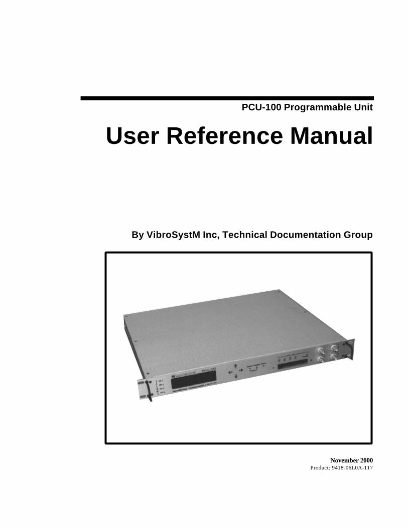
PCU-100 Programmable Unit
User Reference Manual
By VibroSystM Inc, Technical Documentation Group
November 2000Product: 9418-06L0A-117

Copyright © 1999 VibroSystM Inc. Corporation All rights reserved. This document and the PCU operating softwaredescribed herein are protected by copyright laws. Therefore, the manual may not be reproduced without the expresswritten consent of VibroSystM Inc. .
PCU-100 is a registered trademark of VibroSystM Inc.All other brands are the property of their respective manufacturers.
The VibroSystM Inc. Corporation shall not be held responsible for any damages to products, hardware or devices withwhich the aforementioned product is used. The VibroSystM Inc. Corporation shall not be held responsible for any loss ofrevenues, or production, accidental damages or damages pursuant to the use of the aforementioned product.
VibroSystM Inc.2727 East Jacques-Cartier Street
Longueuil, Quebec, CanadaJ4N 1L7
Telephone: (450) 646-2157U.S. Toll Free: 1-800 663-8379
Fax: (450) 646-2164e-mail: [email protected]

PCU-100 Programmable Unit - User Reference Manual Table of Contents • i
TABLE OF CONTENTS
Chapter 1: Introducing the PCU-100 1.11.1 System Features ...............................................................................................................................1.2
1.2 About Digital Signal Processing Technology.............................................................................1.2
1.3 Safety Precautions...........................................................................................................................1.31.3.1 Installation and Handling ............................................................................................1.3
1.4 Warranty Information......................................................................................................................1.4
Chapter 2: System Hardware 2.12.1 Parts and Controls ...........................................................................................................................2.2
2.2 Using Task Modules .......................................................................................................................2.72.2.1 Overview........................................................................................................................2.72.2.2 The Vibration Input Module .....................................................................................2.102.2.3 The Processing and Analog Output Module .........................................................2.162.2.4 The Internal Relay Module........................................................................................2.212.2.5 The Internal Relay Driver Module with External Relay Card................................2.232.2.6 The Digital I/O and 1/rev Module ............................................................................2.27
2.3 Electrical Supply.............................................................................................................................2.382.3.1 Input..............................................................................................................................2.382.3.2 Ground..........................................................................................................................2.38
2.4 The ICRS-485 Communication Interface.....................................................................................2.392.4.1 Overview of the ZOOM System...............................................................................2.392.4.2 System requirements ..................................................................................................2.402.4.3 Operation......................................................................................................................2.402.4.4 Connections.................................................................................................................2.42
Chapter 3: The User Interface 3.13.1 System Ergonomics .........................................................................................................................3.2
3.1.1 Visualization Menus.....................................................................................................3.23.1.2 Entering and Leaving Menus......................................................................................3.33.1.3 Scrolling through Menus.............................................................................................3.33.1.4 Selecting an Option ......................................................................................................3.43.1.5 Canceling a Selected Option .......................................................................................3.43.1.6 Setting the Current Date ..............................................................................................3.53.1.7 Setting the Current Time ..............................................................................................3.73.1.8 Entering a Number........................................................................................................3.93.1.9 Entering an Alphanumeric String .............................................................................3.113.1.10 Selecting a Tag..........................................................................................................3.133.1.11 Accessing Bargraphs and Acknowledging Alarms ............................................3.143.1.12 Saving Configuration Parameters ...........................................................................3.173.1.13 Updating Configuration Parameters.......................................................................3.183.1.14 Updating System Software ......................................................................................3.193.1.15 Misceleaneous User Prompts .................................................................................3.213.1.16 Displaying Task Module Assignment...................................................................3.22
3.2 The Configuration Process...........................................................................................................3.233.2.1 General System Parameters........................................................................................3.243.2.2 Vibration Input Modules ...........................................................................................3.323.2.3 Processing and Analog Output Module .................................................................3.393.2.4 Digital I/O and 1/rev Module ....................................................................................3.553.2.5 Internal Relay Module and External Relay Card Unit ............................................3.583.2.6 Logic Parameters .........................................................................................................3.623.2.7 Monitoring Displays ..................................................................................................3.67
ii • Table of Contents PCU-100 Programmable Unit - User Reference Manual
Chapter 4: Technical Specifications 4.14.1 Task Modules...................................................................................................................................4.1
4.2 RS-485 Communication Interface (optional) ................................................................................4.3
4.3 Data Storage Section.......................................................................................................................4.3
4.4 PCU-100 General...............................................................................................................................4.3
4.5. Electrical Supply..............................................................................................................................4.4
Appendix A: Unit Configuration A.1
Appendix B: Process Overview B.1
Appendix C: The VibraWatch Software Menu Structure C.1
Appendix E: Tag Selection Chart D.1
Index
PCU-100 Programmable Unit - User Reference Manual Chapter I: Introducing the PCU-100 •••• 1.1
Chapter 1
Introducing the PCU-100
Welcome to a new dimension in customizable signal monitoring and data processing.With the advent of the PCU-100, VibroSystM affirms its commitment to thevibration monitoring industry by putting state-of-the-art technology at work in thefield to provide extensive machine monitoring and protection.
The PCU-100 is a programmable signal conditioning and data management unitdesigned to process raw vibration measurements from up to eight measuring pointslocated on one or several generators. The unit features large scale componentintegration with an array of dedicated data processors. This design enables thecentral processing unit (CPU) to share tasks with those processors runningsimultaneously, thus preventing overloading from routine operations.
The unit is industry compliant. It connects to a broad range of proximity,acceleration and velocity sensors and, with several keystrokes, can be programmed tomatch their exact operating characteristics. Furthermore, the PCU-100 keeps up withyour growing monitoring and protection needs by providing eight expansion slots tomix and match the family of optional task modules.
The PCU-100 is also a feature-rich event management system offering a wide rangeof evolutive options. For instance, real-time monitoring combined with voting logicmakes it possible to focus on those events which could prove detrimental to the safeoperation of your machine. Machine protection and user notification also impliesaccess to alarm-triggered relays for connectivity to various annunciation or controldevices.
Users of VibroSystM’s ZOOM monitoring system can also take advantage of thePCU-100 unit’s ability to interface with the acquisition units. When in place, thecommunication interface option sends measurement data to the AGMS or ZOOMacquisition unit for storage into the ZOOM database and correlation with otherZOOM parameters for overall machine condition.
1.2 •••• Chapter I: Introducing the PCU-100 PCU-100 Programmable Unit - User Reference Manual
1.1: System FeaturesHere are the main features of the PCU-100 unit:
• fully programmable, multitasking instrumentation unit for vibrationmonitoring, machine protection, and real-time measurement display;
• compatibility with VibroSystM’s full range of proximity andacceleration measurement sensors and most third-party input devices;
• modular design allowing the mix and match and upgrade capabilities ofVibroSystM's task modules over eight expansion slots;
• two front-loading PCMCIA card sockets convenient fordownloading/uploading user configurations and new system software;
• continuous high-speed sampling and processing rate up to 4 065 s/sec;
• DSP technology onboard selected task modules for optimum processingpower and resolution;
• easy-to-read front panel alphanumerical display with navigation keypadfor quick access to menu selections and measurement characteristics;
• high-contrast LED indicators suitable for notification on alarmtriggering, measuring chain condition (OK), and system status;
• 12 selectable bargraphs for real-time display of processed outputs;
• voting logic (1 or 0) capability to extend the range of reported events;
• digital inputs for control of system features by remote switches anddigital outputs for remote annunciation of system events and alarms;
• four front-panel BNC connectors supplying conditioned vibrationoutputs to portable display instrumentation;
• optional RS-485 communication capability for measurement datatransmission to AGMS or ZOOM acquisition units;
• 1 U high, low profile unit, can be installs almost anywhere.
1.2: About Digital Signal Processing (DSP) TechnologyThe PCU-100 unit employs signal processing (DSP) technology. This state-of-the-artfeature enables signal processing right at the point of entry of the signals, thusrelieving the main CPU. DSP processors are mounted on the vibration input moduleas well as on the processing and analog output module, performing such functions asnoise filtering, linearization and signal translation into user selected parameterinformation. The information available through digital processing of vibrationmeasurements includes AC, RMS, Peak, Average, Svector and Smax values.
PCU-100 Programmable Unit - User Reference Manual Chapter I: Introducing the PCU-100 •••• 1.3
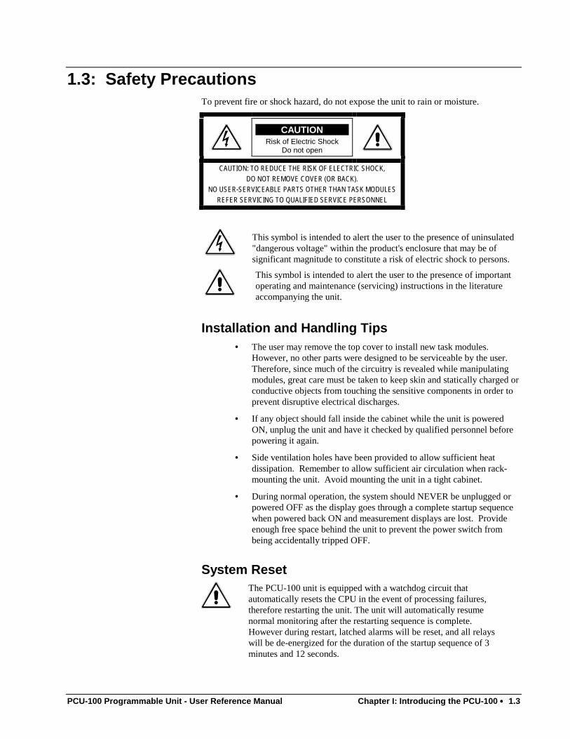
1.3: Safety PrecautionsTo prevent fire or shock hazard, do not expose the unit to rain or moisture.
CAUTIONRisk of Electric Shock
Do not open
CAUTION: TO REDUCE THE RISK OF ELECTRIC SHOCK,DO NOT REMOVE COVER (OR BACK).
NO USER-SERVICEABLE PARTS OTHER THAN TASK MODULESREFER SERVICING TO QUALIFIED SERVICE PERSONNEL
This symbol is intended to alert the user to the presence of uninsulated"dangerous voltage" within the product's enclosure that may be ofsignificant magnitude to constitute a risk of electric shock to persons.
This symbol is intended to alert the user to the presence of importantoperating and maintenance (servicing) instructions in the literatureaccompanying the unit.
Installation and Handling Tips• The user may remove the top cover to install new task modules.
However, no other parts were designed to be serviceable by the user.Therefore, since much of the circuitry is revealed while manipulatingmodules, great care must be taken to keep skin and statically charged orconductive objects from touching the sensitive components in order toprevent disruptive electrical discharges.
• If any object should fall inside the cabinet while the unit is poweredON, unplug the unit and have it checked by qualified personnel beforepowering it again.
• Side ventilation holes have been provided to allow sufficient heatdissipation. Remember to allow sufficient air circulation when rack-mounting the unit. Avoid mounting the unit in a tight cabinet.
• During normal operation, the system should NEVER be unplugged orpowered OFF as the display goes through a complete startup sequencewhen powered back ON and measurement displays are lost. Provideenough free space behind the unit to prevent the power switch frombeing accidentally tripped OFF.
System ResetThe PCU-100 unit is equipped with a watchdog circuit thatautomatically resets the CPU in the event of processing failures,therefore restarting the unit. The unit will automatically resumenormal monitoring after the restarting sequence is complete.However during restart, latched alarms will be reset, and all relayswill be de-energized for the duration of the startup sequence of 3minutes and 12 seconds.
1.4 •••• Chapter I: Introducing the PCU-100 PCU-100 Programmable Unit - User Reference Manual
1.4: Warranty Information
LIMITED WARRANTYVibroSystM warrants the PCU-100 and its task modules against defective parts andworkmanship for a period of twelve (12) months from date of commissioning or fora maximum of eighteen (18) months after date of purchase. No other warrantyapplies.
This precision instrument requires no field calibration and contains no user-serviceable components except for replacement or upgrade of task modules. ThePCU-100 programmable unit is factory-configured to operate strictly according tothe specifications set forth and agreed upon by the customer. Any attempt tomodify this unit represents a violation of the terms and conditions of the expressedwarranty. We cannot be held responsible for erroneous data resulting frommodified configuration settings. The task of reviewing software settings is left tothe initiative of the experienced user.
If any item is found to be defective and therefore needs to be replaced, please usethe original packing box, when possible, to send it back to us. In cases where thebox is damaged, use any other box as long as the items are well packed andprotected against shocks. Our shipping address is:
VibroSystM Inc.2727 East Jacques-Cartier Street
Longueuil, Quebec, CanadaJ4N 1L7
PCU-100 Programmable Unit - User Reference Manual Chapter II: Using the System •••• 2.1
Chapter 2
System Hardware
The PCU-100 is a versatile unit which connects to a broad family of sensors. Afterassessing the monitoring needs of the plant, each PCU unit can be factory-customized and shipped with the required hardware in the form of task modules. Theuser then uses the front panel keypad to configure the new modules according to hisown specifications and preferences and switch to on-line monitoring. Real-time alarmreporting is done through front panel LEDs while on-board relays are tripped forannunciation by field equipment. Measurement readout uses the two-line VFDdisplay. The user may also choose to route raw or processed information to third-party analog display units by way of the front-panel BNC connectors or to interfacethe PCU with the ZOOM monitoring system through RS-485 communication.
This chapter is pivotal to adequate operation of the PCU-100 unit. It is divided intofour sections:
Section I: System Parts and Controls identifies and briefly describes all user-accessible parts and controls found on both front and rear panels as well as on theinternal circuit board which hosts the task modules.
Section II: Using Task Modules surveys the various task modules available andelaborates on the mix and match possibilities that best suit practical monitoring andprotection applications. Installation procedures as well as field wiring diagrams arealso included for each task module.
Section III: Electrical Supply focuses on the power supply and instructs users how toprovide adequate power to the PCU unit in regards to worldwide use.
Section IV: The Communication Interface discusses the communication interfaceoption available for all PCU units equipped with system software v. 1.40 and later.
Note: Configuration and operation of the PCU-100 software are the subject ofChapter III entitled: The User Interface.
2.2 •••• Chapter II: Using the System PCU-100 Programmable Unit - User Reference Manual
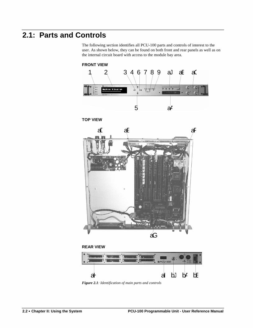
2.1: Parts and ControlsThe following section identifies all PCU-100 parts and controls of interest to theuser. As shown below, they can be found on both front and rear panels as well as onthe internal circuit board with access to the module bay area.
FRONT VIEW
1 2 3 4 6 7 8 9 aJ aB aC
aA5
Machine Vibration Machine Vibration Machine Vibration Machine Vibration •••••••••••••••• •••••••••••••••• •••••••••••••••• ••••••••••••••••
TOP VIEW
aD aE
aG
aF
REAR VIEW
aH bJ bA bBaIFigure 2.1: Identification of main parts and controls
PCU-100 Programmable Unit - User Reference Manual Chapter II: Using the System •••• 2.3
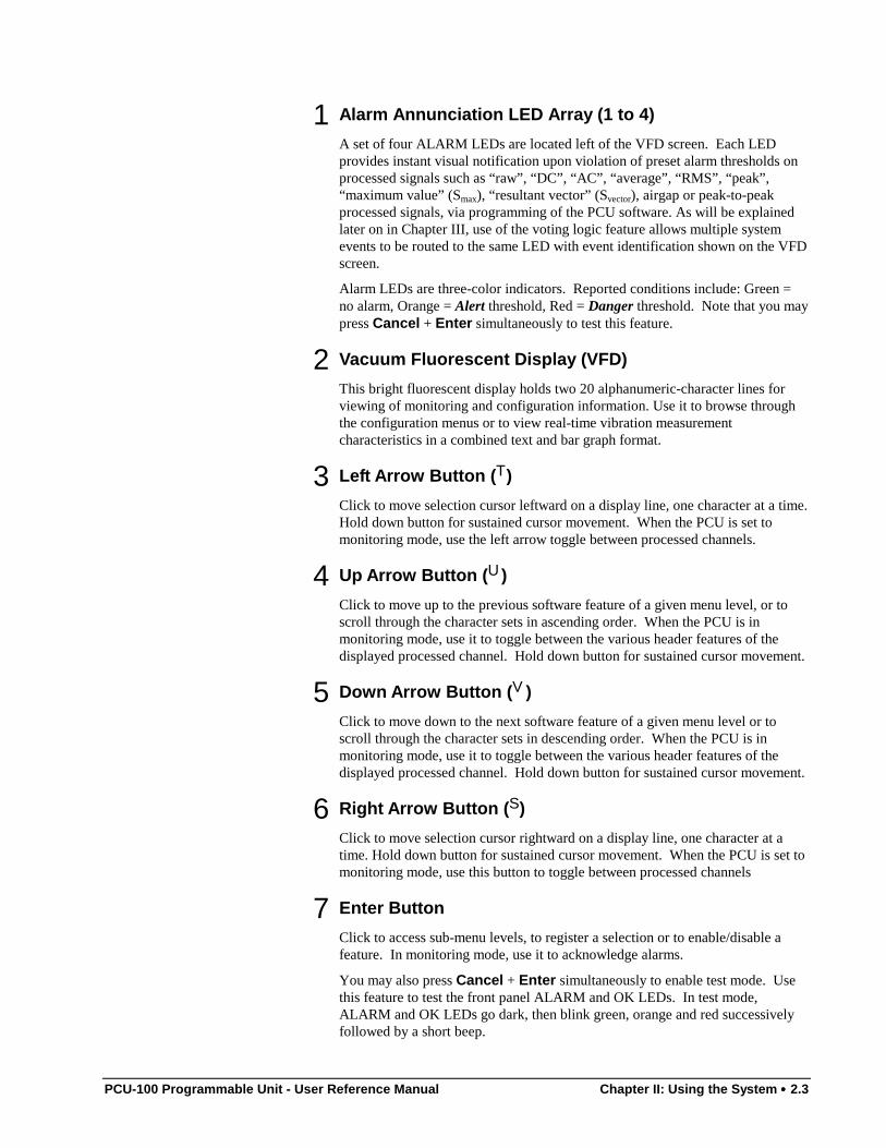
1Alarm Annunciation LED Array (1 to 4)
A set of four ALARM LEDs are located left of the VFD screen. Each LEDprovides instant visual notification upon violation of preset alarm thresholds onprocessed signals such as “raw”, “DC”, “AC”, “average”, “RMS”, “peak”,“maximum value” (Smax), “resultant vector” (Svector), airgap or peak-to-peakprocessed signals, via programming of the PCU software. As will be explainedlater on in Chapter III, use of the voting logic feature allows multiple systemevents to be routed to the same LED with event identification shown on the VFDscreen.
Alarm LEDs are three-color indicators. Reported conditions include: Green =no alarm, Orange = Alert threshold, Red = Danger threshold. Note that you maypress Cancel + Enter simultaneously to test this feature.
2Vacuum Fluorescent Display (VFD)
This bright fluorescent display holds two 20 alphanumeric-character lines forviewing of monitoring and configuration information. Use it to browse throughthe configuration menus or to view real-time vibration measurementcharacteristics in a combined text and bar graph format.
3Left Arrow Button (T)
Click to move selection cursor leftward on a display line, one character at a time.Hold down button for sustained cursor movement. When the PCU is set tomonitoring mode, use the left arrow toggle between processed channels.
4 Up Arrow Button (U)
Click to move up to the previous software feature of a given menu level, or toscroll through the character sets in ascending order. When the PCU is inmonitoring mode, use it to toggle between the various header features of thedisplayed processed channel. Hold down button for sustained cursor movement.
5Down Arrow Button (V)
Click to move down to the next software feature of a given menu level or toscroll through the character sets in descending order. When the PCU is inmonitoring mode, use it to toggle between the various header features of thedisplayed processed channel. Hold down button for sustained cursor movement.
6Right Arrow Button (S)
Click to move selection cursor rightward on a display line, one character at atime. Hold down button for sustained cursor movement. When the PCU is set tomonitoring mode, use this button to toggle between processed channels
7Enter Button
Click to access sub-menu levels, to register a selection or to enable/disable afeature. In monitoring mode, use it to acknowledge alarms.
You may also press Cancel + Enter simultaneously to enable test mode. Usethis feature to test the front panel ALARM and OK LEDs. In test mode,ALARM and OK LEDs go dark, then blink green, orange and red successivelyfollowed by a short beep.
2.4 •••• Chapter II: Using the System PCU-100 Programmable Unit - User Reference Manual
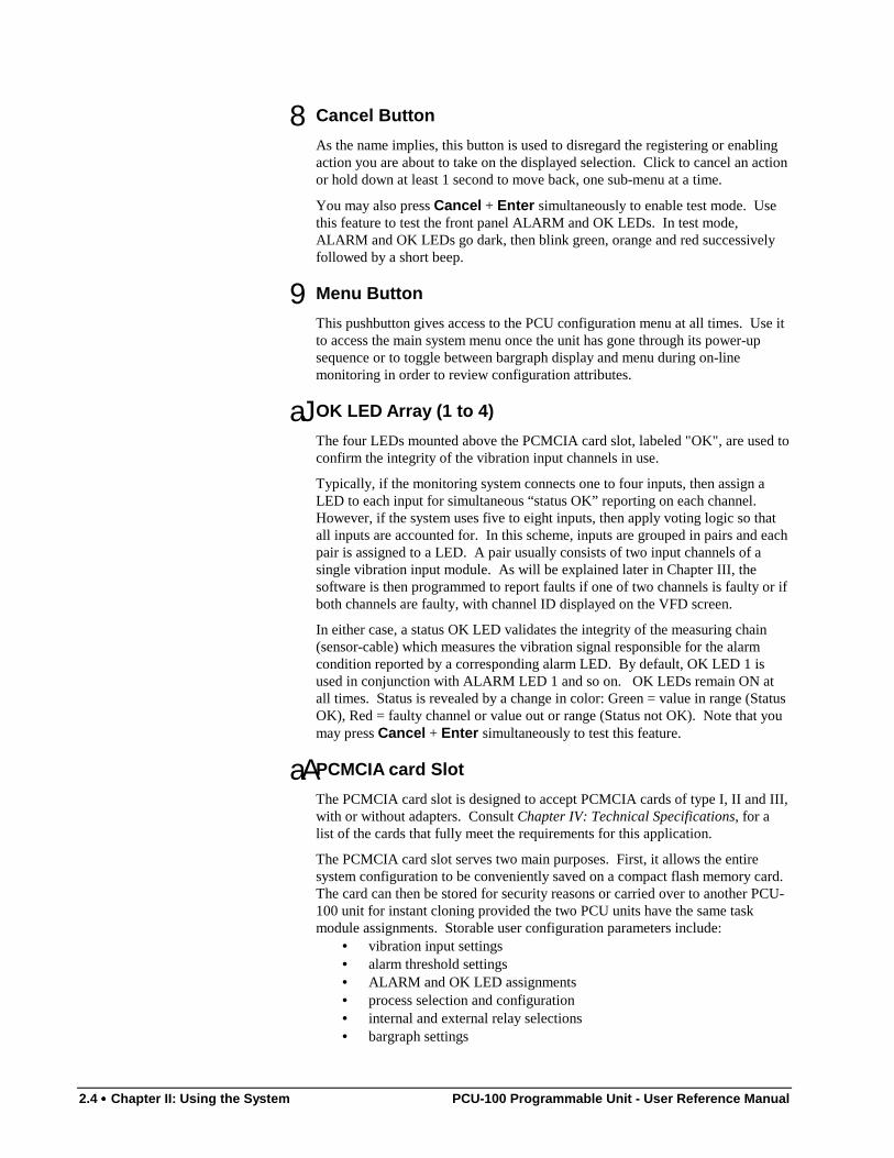
8Cancel Button
As the name implies, this button is used to disregard the registering or enablingaction you are about to take on the displayed selection. Click to cancel an actionor hold down at least 1 second to move back, one sub-menu at a time.
You may also press Cancel + Enter simultaneously to enable test mode. Usethis feature to test the front panel ALARM and OK LEDs. In test mode,ALARM and OK LEDs go dark, then blink green, orange and red successivelyfollowed by a short beep.
9Menu Button
This pushbutton gives access to the PCU configuration menu at all times. Use itto access the main system menu once the unit has gone through its power-upsequence or to toggle between bargraph display and menu during on-linemonitoring in order to review configuration attributes.
aJOK LED Array (1 to 4)
The four LEDs mounted above the PCMCIA card slot, labeled "OK", are used toconfirm the integrity of the vibration input channels in use.
Typically, if the monitoring system connects one to four inputs, then assign aLED to each input for simultaneous “status OK” reporting on each channel.However, if the system uses five to eight inputs, then apply voting logic so thatall inputs are accounted for. In this scheme, inputs are grouped in pairs and eachpair is assigned to a LED. A pair usually consists of two input channels of asingle vibration input module. As will be explained later in Chapter III, thesoftware is then programmed to report faults if one of two channels is faulty or ifboth channels are faulty, with channel ID displayed on the VFD screen.
In either case, a status OK LED validates the integrity of the measuring chain(sensor-cable) which measures the vibration signal responsible for the alarmcondition reported by a corresponding alarm LED. By default, OK LED 1 isused in conjunction with ALARM LED 1 and so on. OK LEDs remain ON atall times. Status is revealed by a change in color: Green = value in range (StatusOK), Red = faulty channel or value out or range (Status not OK). Note that youmay press Cancel + Enter simultaneously to test this feature.
aAPCMCIA card Slot
The PCMCIA card slot is designed to accept PCMCIA cards of type I, II and III,with or without adapters. Consult Chapter IV: Technical Specifications, for alist of the cards that fully meet the requirements for this application.
The PCMCIA card slot serves two main purposes. First, it allows the entiresystem configuration to be conveniently saved on a compact flash memory card.The card can then be stored for security reasons or carried over to another PCU-100 unit for instant cloning provided the two PCU units have the same taskmodule assignments. Storable user configuration parameters include:
• vibration input settings• alarm threshold settings• ALARM and OK LED assignments• process selection and configuration• internal and external relay selections• bargraph settings
PCU-100 Programmable Unit - User Reference Manual Chapter II: Using the System •••• 2.5
PCMCIA slots are also provided to allow field upgrade of the system software.VibroSystM will inform clients of new releases as they become available. Otherapplications that will take advantage of this interface are also planned.
When inserting a card, press gently to snap into position. Release card bypressing the eject button. The activity LED located next to the eject lever lightswhen a card is inserted. Consult Chapter III: The User Interface to learn how toaccess the system software in order to download or upload software.
aBPower LED (SYSTEM)
This is the Power indicator LED. It remains ON (green light) for as long aspower is applied to the unit. The same power LED indicator can be found on theback panel, between the two fuse compartments.
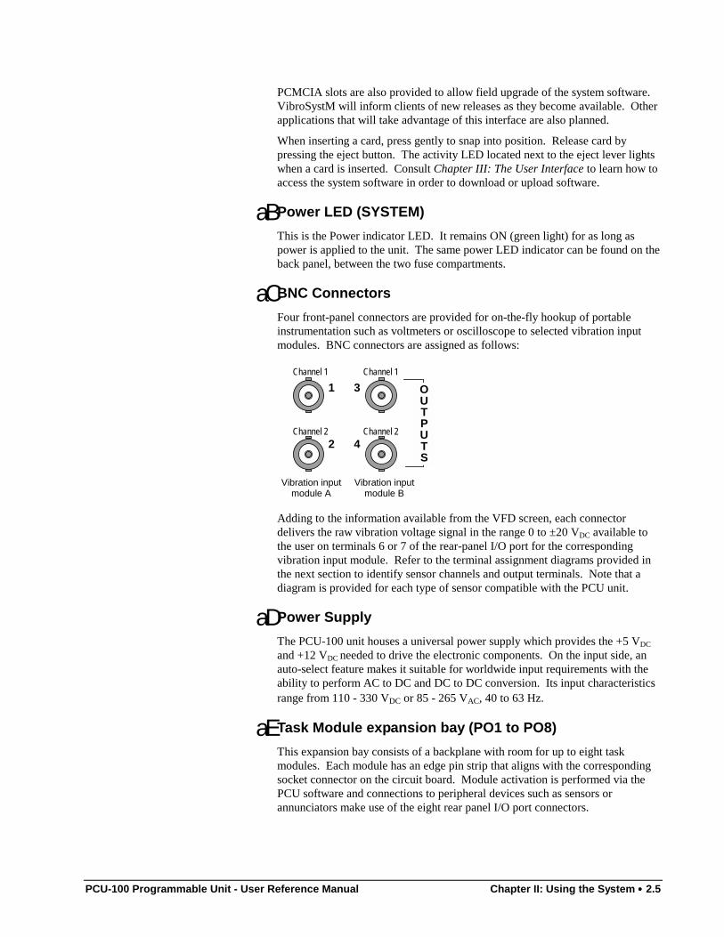
aCBNC Connectors
Four front-panel connectors are provided for on-the-fly hookup of portableinstrumentation such as voltmeters or oscilloscope to selected vibration inputmodules. BNC connectors are assigned as follows:
1 3
2 4
OUTPUTS
Vibration inputmodule B
Vibration inputmodule A
Channel 1 Channel 1
Channel 2 Channel 2
Adding to the information available from the VFD screen, each connectordelivers the raw vibration voltage signal in the range 0 to ±20 VDC available tothe user on terminals 6 or 7 of the rear-panel I/O port for the correspondingvibration input module. Refer to the terminal assignment diagrams provided inthe next section to identify sensor channels and output terminals. Note that adiagram is provided for each type of sensor compatible with the PCU unit.
aD Power Supply
The PCU-100 unit houses a universal power supply which provides the +5 VDC
and +12 VDC needed to drive the electronic components. On the input side, anauto-select feature makes it suitable for worldwide input requirements with theability to perform AC to DC and DC to DC conversion. Its input characteristicsrange from 110 - 330 VDC or 85 - 265 VAC, 40 to 63 Hz.
aE Task Module expansion bay (PO1 to PO8)
This expansion bay consists of a backplane with room for up to eight taskmodules. Each module has an edge pin strip that aligns with the correspondingsocket connector on the circuit board. Module activation is performed via thePCU software and connections to peripheral devices such as sensors orannunciators make use of the eight rear panel I/O port connectors.
2.6 •••• Chapter II: Using the System PCU-100 Programmable Unit - User Reference Manual
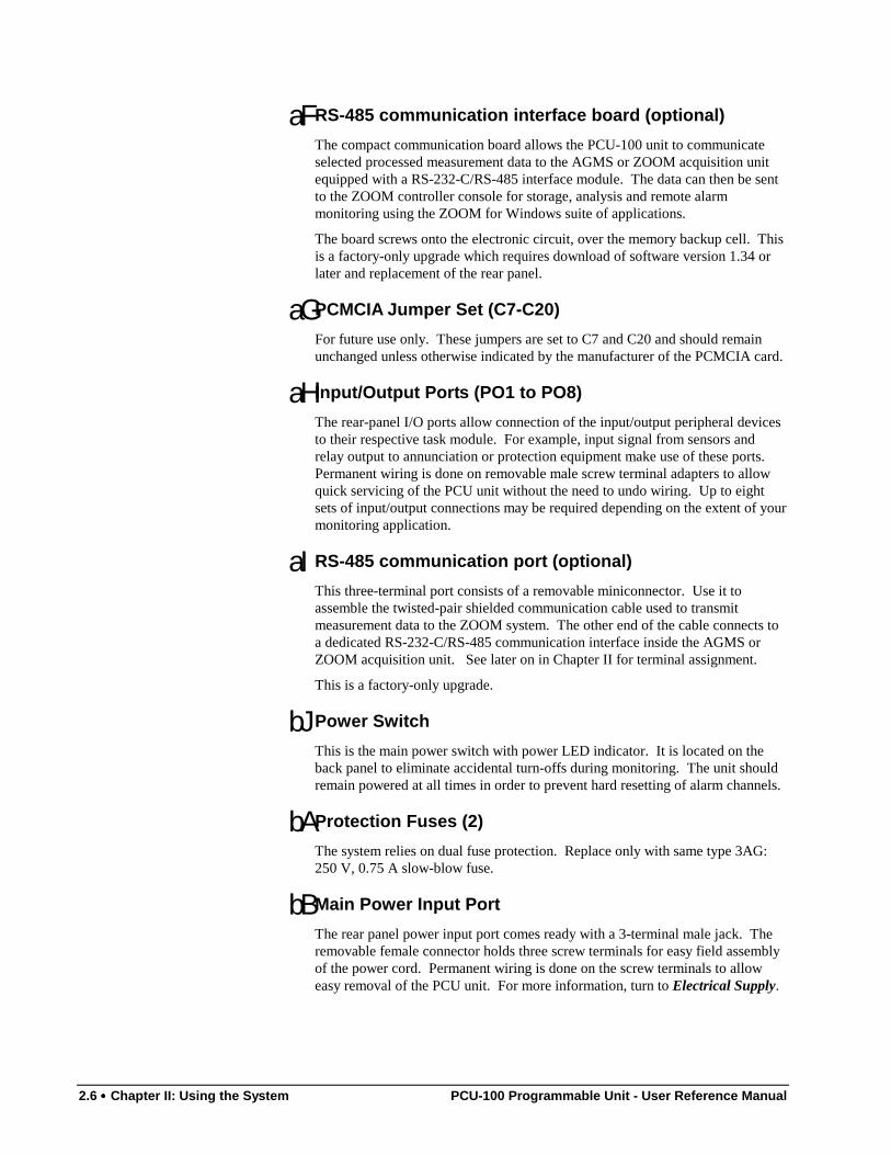
aFRS-485 communication interface board (optional)
The compact communication board allows the PCU-100 unit to communicateselected processed measurement data to the AGMS or ZOOM acquisition unitequipped with a RS-232-C/RS-485 interface module. The data can then be sentto the ZOOM controller console for storage, analysis and remote alarmmonitoring using the ZOOM for Windows suite of applications.
The board screws onto the electronic circuit, over the memory backup cell. Thisis a factory-only upgrade which requires download of software version 1.34 orlater and replacement of the rear panel.
aGPCMCIA Jumper Set (C7-C20)
For future use only. These jumpers are set to C7 and C20 and should remainunchanged unless otherwise indicated by the manufacturer of the PCMCIA card.
aH Input/Output Ports (PO1 to PO8)
The rear-panel I/O ports allow connection of the input/output peripheral devicesto their respective task module. For example, input signal from sensors andrelay output to annunciation or protection equipment make use of these ports.Permanent wiring is done on removable male screw terminal adapters to allowquick servicing of the PCU unit without the need to undo wiring. Up to eightsets of input/output connections may be required depending on the extent of yourmonitoring application.
aIRS-485 communication port (optional)
This three-terminal port consists of a removable miniconnector. Use it toassemble the twisted-pair shielded communication cable used to transmitmeasurement data to the ZOOM system. The other end of the cable connects toa dedicated RS-232-C/RS-485 communication interface inside the AGMS orZOOM acquisition unit. See later on in Chapter II for terminal assignment.
This is a factory-only upgrade.
bJPower Switch
This is the main power switch with power LED indicator. It is located on theback panel to eliminate accidental turn-offs during monitoring. The unit shouldremain powered at all times in order to prevent hard resetting of alarm channels.
bAProtection Fuses (2)
The system relies on dual fuse protection. Replace only with same type 3AG:250 V, 0.75 A slow-blow fuse.
bBMain Power Input Port
The rear panel power input port comes ready with a 3-terminal male jack. Theremovable female connector holds three screw terminals for easy field assemblyof the power cord. Permanent wiring is done on the screw terminals to alloweasy removal of the PCU unit. For more information, turn to Electrical Supply.
PCU-100 Programmable Unit - User Reference Manual Chapter II: Using the System •••• 2.7
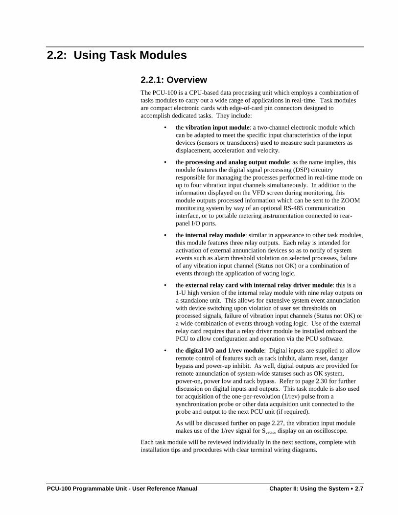
2.2: Using Task Modules
2.2.1: OverviewThe PCU-100 is a CPU-based data processing unit which employs a combination oftasks modules to carry out a wide range of applications in real-time. Task modulesare compact electronic cards with edge-of-card pin connectors designed toaccomplish dedicated tasks. They include:
• the vibration input module: a two-channel electronic module whichcan be adapted to meet the specific input characteristics of the inputdevices (sensors or transducers) used to measure such parameters asdisplacement, acceleration and velocity.
• the processing and analog output module: as the name implies, thismodule features the digital signal processing (DSP) circuitryresponsible for managing the processes performed in real-time mode onup to four vibration input channels simultaneously. In addition to theinformation displayed on the VFD screen during monitoring, thismodule outputs processed information which can be sent to the ZOOMmonitoring system by way of an optional RS-485 communicationinterface, or to portable metering instrumentation connected to rear-panel I/O ports.
• the internal relay module: similar in appearance to other task modules,this module features three relay outputs. Each relay is intended foractivation of external annunciation devices so as to notify of systemevents such as alarm threshold violation on selected processes, failureof any vibration input channel (Status not OK) or a combination ofevents through the application of voting logic.
• the external relay card with internal relay driver module: this is a1-U high version of the internal relay module with nine relay outputs ona standalone unit. This allows for extensive system event annunciationwith device switching upon violation of user set thresholds onprocessed signals, failure of vibration input channels (Status not OK) ora wide combination of events through voting logic. Use of the externalrelay card requires that a relay driver module be installed onboard thePCU to allow configuration and operation via the PCU software.
• the digital I/O and 1/rev module: Digital inputs are supplied to allowremote control of features such as rack inhibit, alarm reset, dangerbypass and power-up inhibit. As well, digital outputs are provided forremote annunciation of system-wide statuses such as OK system,power-on, power low and rack bypass. Refer to page 2.30 for furtherdiscussion on digital inputs and outputs. This task module is also usedfor acquisition of the one-per-revolution (1/rev) pulse from asynchronization probe or other data acquisition unit connected to theprobe and output to the next PCU unit (if required).
As will be discussed further on page 2.27, the vibration input modulemakes use of the 1/rev signal for Svector display on an oscilloscope.
Each task module will be reviewed individually in the next sections, complete withinstallation tips and procedures with clear terminal wiring diagrams.
2.8 •••• Chapter II: Using the System PCU-100 Programmable Unit - User Reference Manual
By incorporating task modules into a modular design, the central processor can focuson software operations, data routing, alarm management, display and communication.The CPU centers around an Intel microprocessor running under MS-DOS allowingconnectivity to conventional PC hardware. This allows PCU units to communicateamong themselves as well as with AGMS and ZOOM acquisition units.
Using task modules requires a thorough understanding of your monitoring andprotection needs. Your planning must account for the actual number of sensors andthe number of protection relays per input or processed signal. Since the PCU unit isfully programmable and extensively customizable, you must mix and match moduleskeeping in mind the requirements and limitations one module sets on other modules.
As discussed in the next paragraphs, many system upgrades can be performed in thefield. Remember however that each task module must be given a specific busaddress through factory-set address DIP switches. The “bus” represents a chainscanned by the system software and each module represents a link in this chain
It is therefore expected that the user be able to provide VibroSystM with a clearlayout of the current configuration when ordering extra modules. This requirementwill allow VSM to properly set the new modules before shipment and thus preventconflicts with preinstalled modules.
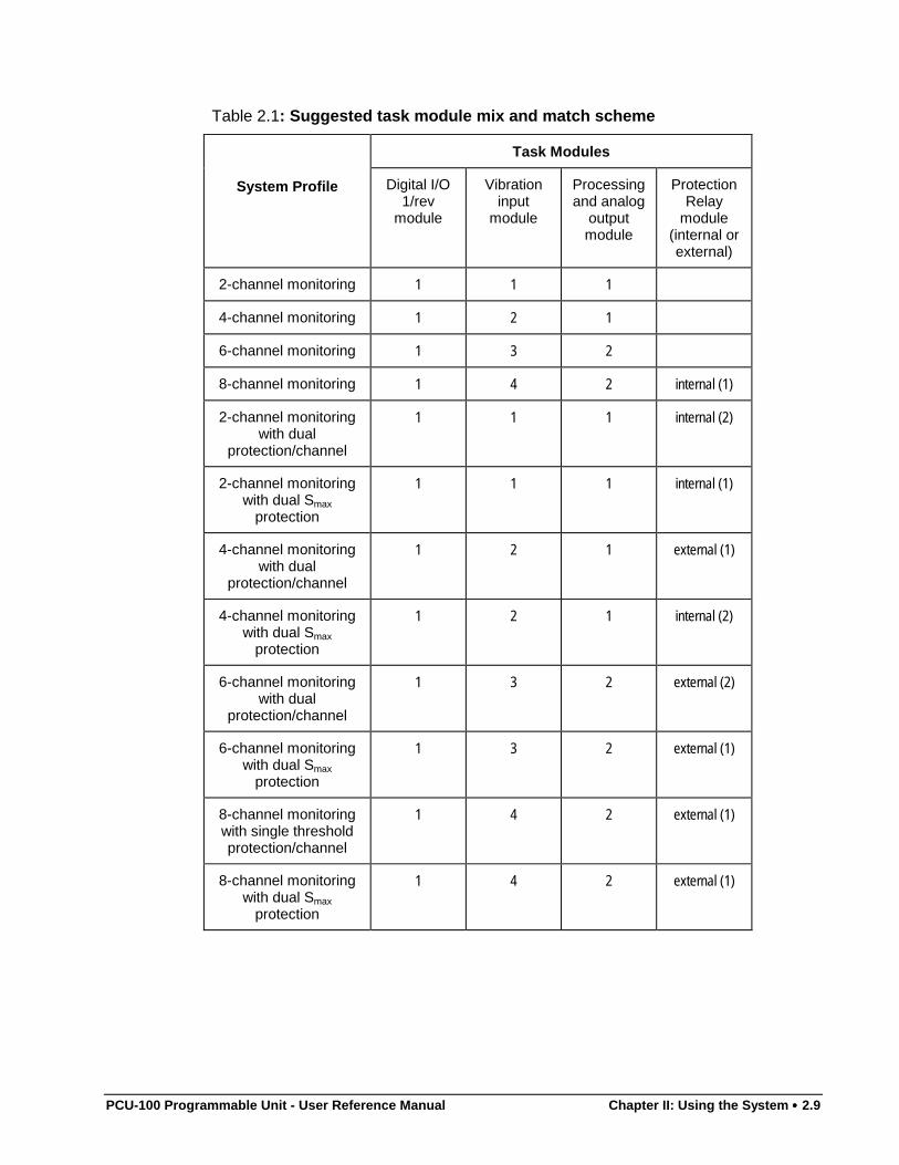
Table 2.1 summarizes typical module combinations with respect to the followingcriteria:
• each PCU unit features 8 expansion slots for up to 8 task modules;
• one digital I/O and 1/rev module is needed for capture of the 1/revsignal required in some applications;
• use of an external relay card requires that an internal relay drivermodule occupy one expansion slot;
• one processing and analog output module is required for each set offour input channels;
• depending on the type of data requested and the extent of machineprotection, the number of vibration input signals may differ from thenumber of available processed analog outputs.
Note that this example makes use of the PCS-10x sensor at the front-end of themeasuring chain.
PCU-100 Programmable Unit - User Reference Manual Chapter II: Using the System •••• 2.9
Table 2.1: Suggested task module mix and match scheme
Task Modules
System Profile Digital I/O1/rev
module
Vibrationinput
module
Processingand analog
outputmodule
ProtectionRelay
module(internal orexternal)
2-channel monitoring 1 1 1
4-channel monitoring 1 2 1
6-channel monitoring 1 3 2
8-channel monitoring 1 4 2 internal (1)
2-channel monitoringwith dual
protection/channel
1 1 1 internal (2)
2-channel monitoringwith dual Smax
protection
1 1 1 internal (1)
4-channel monitoringwith dual
protection/channel
1 2 1 external (1)
4-channel monitoringwith dual Smax
protection
1 2 1 internal (2)
6-channel monitoringwith dual
protection/channel
1 3 2 external (2)
6-channel monitoringwith dual Smax
protection
1 3 2 external (1)
8-channel monitoringwith single thresholdprotection/channel
1 4 2 external (1)
8-channel monitoringwith dual Smax
protection
1 4 2 external (1)
2.10 •••• Chapter II: Using the System PCU-100 Programmable Unit - User Reference Manual
2.2.2: The Vibration Input ModuleAs the name implies, the vibration input module is the point of entry of all sensorsignals into the PCU-100 system. This task module is a dual-channel electronic cardcapable of acquiring and filtering the raw vibration measurement signal collectedfrom a variety of sensing devices. Each module is factory-configured to thecustomer’s requirements for one of the following input sources:
• PCS-series proximity sensors – raw vibration-to-frequency, inputmodule range between 85 kHz to 155 kHz;
• FOA-100 fiber-optic accelerometer – MODE 1 (wide) rawacceleration-to-velocity, input sensitivity: 0.1V/g, maximum input30 gpeak, velocity range 585 mm/s, output ±10V;
• FOA-100 fiber-optic accelerometer – MODE 1I (narrow) rawacceleration-to-velocity, input sensitivity: 0.1V/g, maximum input12 gpeak, velocity range 234 mm/s, output ±10V;
• velocity transducer with bloc conditioner – conditioned velocity-to-voltage, input module range of 0 to -20 V;
• Wilcoxon 797L piezoelectric accelerometer – acceleration-to-voltage:input module range 9 VDC, 17.6 mV peak or 0.035 g; minimumcalibration:0.8 Hz (0dB), 0.16 Hz (3 dB);
• Wilcoxon 797V velocimeter – conditioned velocity-to-voltage, inputrange 8 to 12 VDC, 3.94 mV/mm/sec sensitivity;
• Eddy current proximity transducers with bloc conditioner –conditioned vibration-to-voltage, input module range of 0 to -20 V;
• piezoresistive accelerometer with built-in conditioner – conditionedacceleration-to-current, input module range 0 to 20 mA;
• VM-series air gap sensors with conditioning module – conditioneddisplacement-to-current, input module range 4 to 20 mA.
Regardless of the type of input signal it receives, the vibration input moduleaccomplishes three basic functions.
• First, it collects, at a rate of 4 065 samples/second, the raw or pre-conditioned sensor signals on two separate channels. Signals are thenfiltered and linearized before they are sent to the processing and analogoutput module.
• Second, it generates a linearized 0 to ±20 V dynamic vibration outputavailable to metering equipment through rear-panel I/O ports or front-panel BNC connectors.
• Finally, it serves as a power source rated at a max. 24 V, 15 mA forboth sensor and conditioner (when applicable). This feature isparticularly useful when connecting to unibody accelerometers.
Considering that all configurations of the module basically perform the same tasks,we will limit ourselves to describing the most commonly used in PCU-100 basedapplications: the relative vibration input module which receives the frequency signaltransmitted by the PCS vibration sensor.
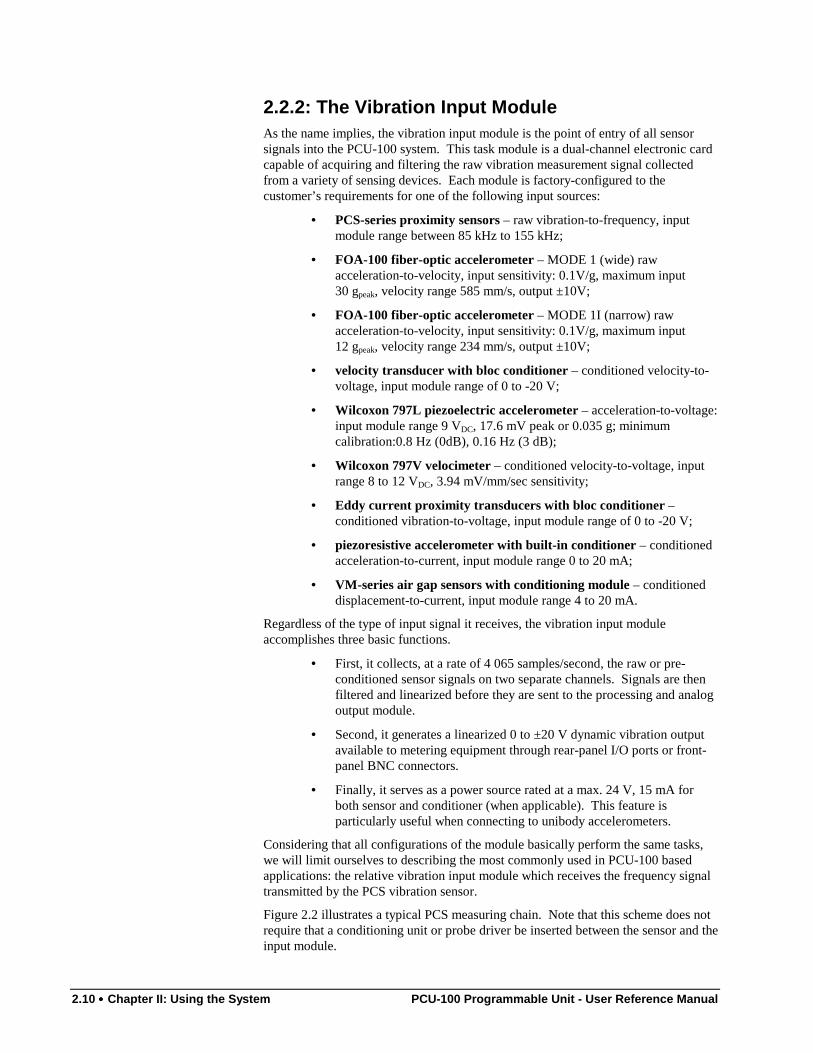
Figure 2.2 illustrates a typical PCS measuring chain. Note that this scheme does notrequire that a conditioning unit or probe driver be inserted between the sensor and theinput module.
PCU-100 Programmable Unit - User Reference Manual Chapter II: Using the System •••• 2.11
PCS-102 capacitiveProximity Probe with
integral cable
Tapping box forconnection of upto three sensors
PCS-typeextension cable
up to 300 m(1000 ft) long
PCU-100programmable
vibration monitoringand protection Unit
Synchronizationsignal
Sensor signal tothe vibrationinput module
Figure 2.2: The PCS-102 measuring chain. The raw vibration information takes the form ofa frequency signal acquired and linearized by the vibration input module. The optionaltapping box extends the range of the sensor's integral cable (either 5, 10 or 15 meters) tomore than 300 meters.
In all cases, the digitally linearized signal is sent to the processing and analog outputmodule for processing and comparison to alarm thresholds for machine protection.The linearized – or raw vibration – signal is also available for user equipment such asvibration meters or oscilloscopes with output levels of -2 to -18V on terminals 6 and7 of the rear panel I/O port assigned to the vibration input module. See Figures 2.4to 2.10 for a complete rundown of I/O port terminal assignment. Front panel BNCconnectors are also provided for capture of the linearized signals by user meteringequipment.
2.2.2.1: Installation and WiringPCU-100 units are shipped fully configured with all specified task modules installed.However if your monitoring or protection needs grow, you can upgrade your existingequipment in the field by adding one or many vibration input modules Whenassessing your needs, consult Table 2.1 to find out if they meet the PCU unit's taskmodule integration capacity. Then contact your local VibroSystM representative sothat the new modules be factory-set to prevent conflicts.
Proceed as follows to install new vibration input modules:
1. Power OFF the unit and remove from rack.
2. Remove top cover by unscrewing the six hex-socket set screws. Thiswill reveal the circuit board and power supply unit. Locate theexpansion bay on the circuit board (see Figure 1 early in this chapter forlocation and identification of parts).
3. Before unpacking the new vibration input module, you must removeany static electricity buildup from your skin. Do so by touching anyconductive material put to ground such as a water pipe.
4. Grab the new task module by the edges and precisely align both pinarrays with corresponding socket strip on the expansion slot. Gentlypress until module is firmly in position.
5. Run one end of the supplied flat cable to the 12-pin strip connectorfound on the back of the task module. Notice the plastic guidemoldings on each connector which prevent reverse connection.
6. Connect the other end of the supplied flat cable to the correspondingI/O port. It consists in a 12-pin strip found on the inner-back panelUse top or bottom pin strips only. Make sure to match the slot number(PO1, PO2, …) printed on the circuit board to that of the inner backpanel (see Figure 2.3).
2.12 •••• Chapter II: Using the System PCU-100 Programmable Unit - User Reference Manual
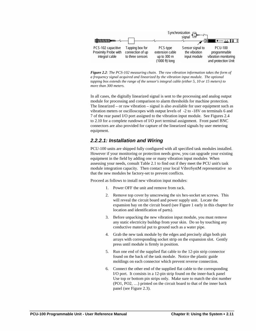
7. Notice two pairs of twisted black/red wires terminated with connectors.Match each connector with the 12-pin strip as shown next. Each pairbrings the raw signal from both vibration channels to the front-panelBNC connectors. See earlier in this chapter for BNC connectorassignment.
PO7
PO8
Pin strip for vibrationinput module
connector on PO7 slot
Pin strip for PO7 rawsignal output to front-panel BNC connector
Pin strip for vibrationinput module
connector on PO8 slot
Pin strip for PO8 rawsignal output to front-panel BNC connector
Figure 2.3: View of the PO7 and PO8 I/O ports as seen from inside the cabinet.
Once module installation is complete, connect the leads of the extension cablecoming from the sensor to the rear panel I/O port. Proceed as follows:
1. Remove the female terminal adapter from its rear panel I/O port.
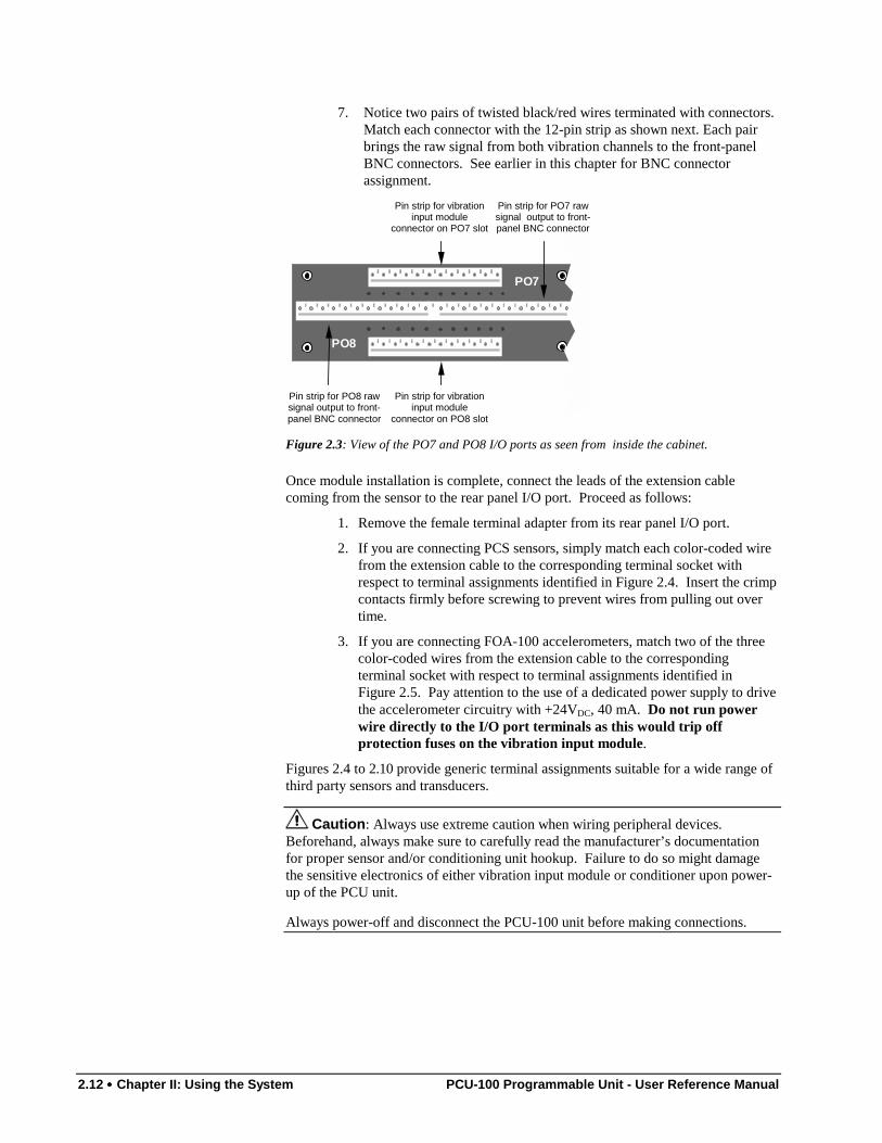
2. If you are connecting PCS sensors, simply match each color-coded wirefrom the extension cable to the corresponding terminal socket withrespect to terminal assignments identified in Figure 2.4. Insert the crimpcontacts firmly before screwing to prevent wires from pulling out overtime.
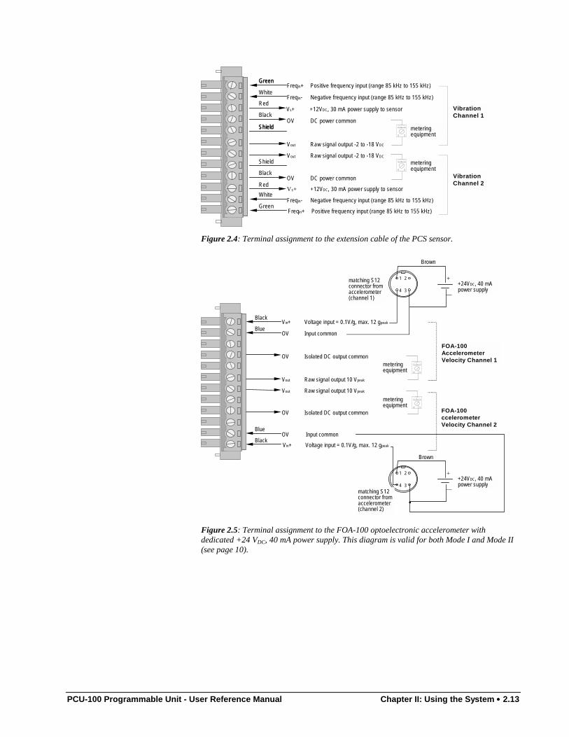
3. If you are connecting FOA-100 accelerometers, match two of the threecolor-coded wires from the extension cable to the correspondingterminal socket with respect to terminal assignments identified inFigure 2.5. Pay attention to the use of a dedicated power supply to drivethe accelerometer circuitry with +24VDC, 40 mA. Do not run powerwire directly to the I/O port terminals as this would trip offprotection fuses on the vibration input module.
Figures 2.4 to 2.10 provide generic terminal assignments suitable for a wide range ofthird party sensors and transducers.
Caution: Always use extreme caution when wiring peripheral devices.Beforehand, always make sure to carefully read the manufacturer’s documentationfor proper sensor and/or conditioning unit hookup. Failure to do so might damagethe sensitive electronics of either vibration input module or conditioner upon power-up of the PCU unit.
Always power-off and disconnect the PCU-100 unit before making connections.
PCU-100 Programmable Unit - User Reference Manual Chapter II: Using the System •••• 2.13
Shield
Shield
Vout Raw signal output -2 to -18 VDC
Vout Raw signal output -2 to -18 VDC
Vs+ +12VDC, 30 mA power supply to sensor
OV DC power common
OV DC power common
Vs+ +12VDC, 30 mA power supply to sensor VibrationChannel 1
VibrationChannel 2
Green
Red
Black
Red
White
Green
Black
White
Green
Shield
Freqin+ Positive frequency input (range 85 kHz to 155 kHz)
Freqin- Negative frequency input (range 85 kHz to 155 kHz)
Freqin- Negative frequency input (range 85 kHz to 155 kHz)
Freqin+ Positive frequency input (range 85 kHz to 155 kHz)
meteringequipment
meteringequipment
Figure 2.4: Terminal assignment to the extension cable of the PCS sensor.
Vout Raw signal output 10 Vpeak
Vout Raw signal output 10 Vpeak
Vin+ Voltage input = 0.1V/g, max. 12 gpeak
OV Input common
OV Input common
OV Isolated DC output common
OV Isolated DC output common
Vin+ Voltage input = 0.1V/g, max. 12 gpeak
FOA-100AccelerometerVelocity Channel 1
FOA-100ccelerometerVelocity Channel 2
meteringequipment
Black
Blue
Black
Blue
matching S12connector fromaccelerometer(channel 1)
meteringequipment
4+24VDC, 40 mApower supply
+
—
matching S12connector fromaccelerometer(channel 2)
•
+24VDC, 40 mApower supply
+
—
Brown
Brown
3
1 2
4 3
1 2
Figure 2.5: Terminal assignment to the FOA-100 optoelectronic accelerometer withdedicated +24 VDC, 40 mA power supply. This diagram is valid for both Mode I and Mode II(see page 10).
2.14 •••• Chapter II: Using the System PCU-100 Programmable Unit - User Reference Manual
Vout Raw signal output ±10 V
Vout Raw signal output ±10 V
Vin+ Voltage input (0 to -20 V)
Vs- -24VDC, 15 mA power supply to conditioner
OV DC power common
OV DC power common
Vs- -24VDC, 15 mA power supply to conditioner
Vin+ Voltage input (0 to -20 V)
VelocityChannel 1
VelocityChannel 2
ShieldShield
Shield
meteringequipment
meteringequipment
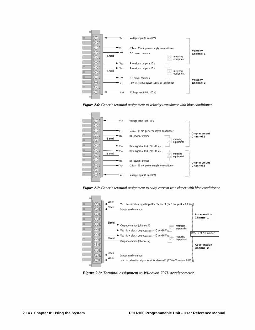
Figure 2.6: Generic terminal assignment to velocity transducer with bloc conditioner.
Vout Raw signal output -2 to -18 VDC
Vout Raw signal output -2 to -18 VDC
Vin+ Voltage input (0 to -20 V)
Vs- -24VDC, 15 mA power supply to conditioner
OV DC power common
OV DC power common
Vs- -24VDC, 15 mA power supply to conditioner
Vin+ Voltage input (0 to -20 V)
DisplacementChannel 1
DisplacementChannel 2
ShieldShield
Shield
meteringequipment
meteringequipment
Figure 2.7: Generic terminal assignment to eddy-current transducer with bloc conditioner.
Shield
Shield
Vout Raw signal output peak-peak –10 to +10 VDC
Vout Raw signal output peak-peak –10 to +10 VDC
AccelerationChannel 1
AccelerationChannel 2
White
Black
Black
White
Shield
Vi+ acceleration signal input for channel 2 (17.6 mV peak = 0.035 g)
Input signal common
Input signal common
Vi+ acceleration signal input for channel 1 (17.6 mV peak = 0.035 g)
meteringequipment
Output common (channel 1)
Output common (channel 2)
meteringequipment
10VDC = 68.91 mm/sec
Figure 2.8: Terminal assignment to Wilcoxon 797L accelerometer.
PCU-100 Programmable Unit - User Reference Manual Chapter II: Using the System •••• 2.15
Shield
Shield
Vout Raw signal output 0 to 10 VDC
Vout Raw signal output 0 to 10 VDC
VelocityChannel 1
VelocityChannel 2
White
Black
Black
White
Shield
Vi+ Velocity signal input for channel 2
Input signal common
Input signal common
Vi+ Velocity signal input for channel 1
meteringequipment
Output common (channel 1)
Output common (channel 2)
meteringequipment
Velocity (mm/s)peak =Voutpeak / 0.352
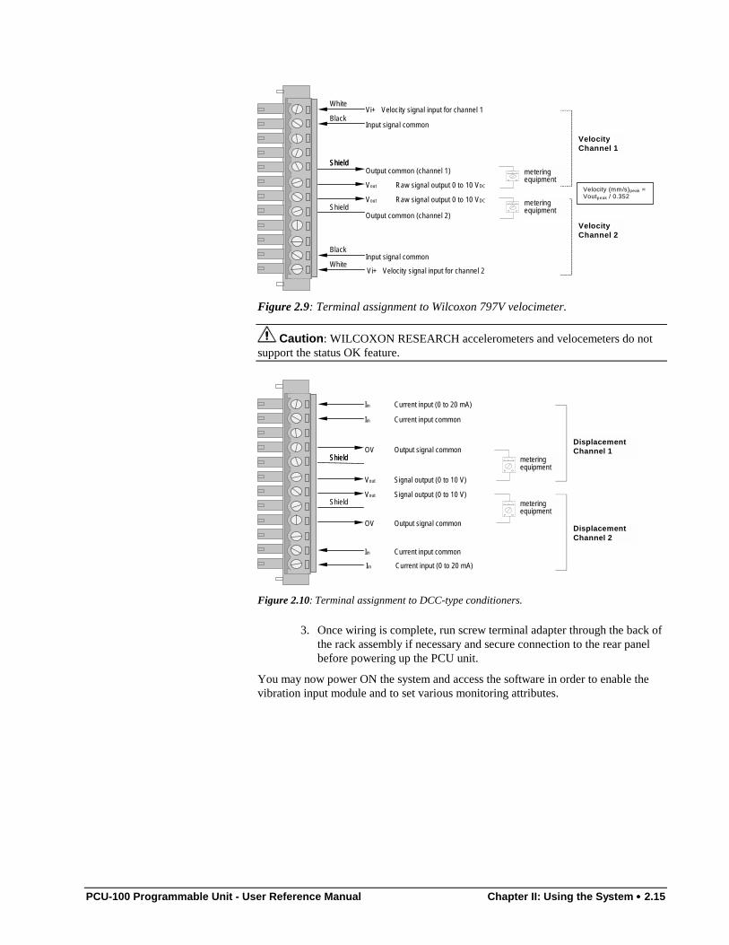
Figure 2.9: Terminal assignment to Wilcoxon 797V velocimeter.
Caution: WILCOXON RESEARCH accelerometers and velocemeters do notsupport the status OK feature.
Vout Signal output (0 to 10 V)
Vout Signal output (0 to 10 V)
Iin Current input (0 to 20 mA)
Iin Current input common
Iin Current input common
OV Output signal common
OV Output signal common
Iin Current input (0 to 20 mA)
DisplacementChannel 1
DisplacementChannel 2
ShieldShield
Shield
meteringequipment
meteringequipment
Figure 2.10: Terminal assignment to DCC-type conditioners.
3. Once wiring is complete, run screw terminal adapter through the back ofthe rack assembly if necessary and secure connection to the rear panelbefore powering up the PCU unit.
You may now power ON the system and access the software in order to enable thevibration input module and to set various monitoring attributes.
2.16 •••• Chapter II: Using the System PCU-100 Programmable Unit - User Reference Manual
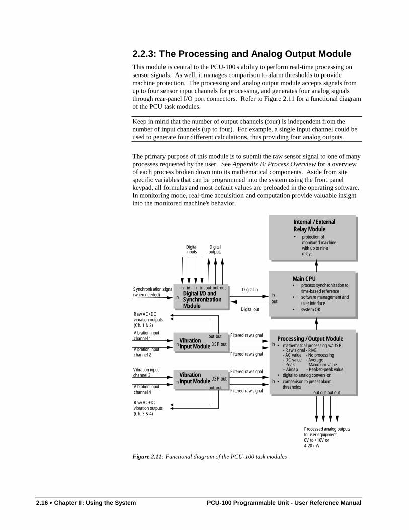
2.2.3: The Processing and Analog Output ModuleThis module is central to the PCU-100's ability to perform real-time processing onsensor signals. As well, it manages comparison to alarm thresholds to providemachine protection. The processing and analog output module accepts signals fromup to four sensor input channels for processing, and generates four analog signalsthrough rear-panel I/O port connectors. Refer to Figure 2.11 for a functional diagramof the PCU task modules.
Keep in mind that the number of output channels (four) is independent from thenumber of input channels (up to four). For example, a single input channel could beused to generate four different calculations, thus providing four analog outputs.
The primary purpose of this module is to submit the raw sensor signal to one of manyprocesses requested by the user. See Appendix B: Process Overview for a overviewof each process broken down into its mathematical components. Aside from sitespecific variables that can be programmed into the system using the front panelkeypad, all formulas and most default values are preloaded in the operating software.In monitoring mode, real-time acquisition and computation provide valuable insightinto the monitored machine's behavior.
Vibration inputchannel 1
Filtered raw signal
Filtered raw signal
Processing / Output Module• mathematical processing w/ DSP:
- Raw signal - RMS- AC value - No processing- DC value - Average- Peak - Maximum value– Airgap - Peak-to-peak value
• digital to analog conversion• comparison to preset alarm
thresholdsin
in
outoutout
Vibration inputchannel 2
Vibration inputchannel 3
Vibration inputchannel 4
Filtered raw signal
Filtered raw signal
Main CPU• process synchronization to
time-based reference• software management and
user interface• system OK
Internal / ExternalRelay Module• protection of
monitored machinewith up to ninerelays.
Processed analog outputsto user equipment:0V to +10V or4-20 mA
Digital I/O andSynchronizationModule
inSynchronization signal(when needed)
Digital in
Digitalinputs
Digitaloutputs
inout
out out outin in in in
out
in DSP outVibrationInput Module
out out
inDSP out
VibrationInput Module
out out
Raw AC+DCvibration outputs(Ch. 1 & 2)
Raw AC+DCvibration outputs(Ch. 3 & 4)
Digital out
Figure 2.11: Functional diagram of the PCU-100 task modules
PCU-100 Programmable Unit - User Reference Manual Chapter II: Using the System •••• 2.17
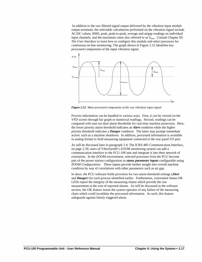
In addition to the raw filtered signal output delivered by the vibration input moduleoutput terminals, the selectable calculations performed on the vibration signal includeAC/DC values, RMS, peak, peak-to-peak, average and airgap readings on individualinput channels, and the maximum value also referred to as Smax. Consult Chapter III:The User Interface to learn how to configure this module and select processes forcontinuous on-line monitoring. The graph shown in Figure 2.12 identifies keyprocessed components of the input vibration signal.
XPeak
XPeak-Peak
XRMS
XAverage
t
X (t)
XRMS
Figure 2.12: Main processed components of the raw vibration input signal.
Process information can be handled in various ways. First, it can be viewed on theVFD screen through bar graph or numerical readings. Second, readings can becompared with user-set dual alarm thresholds for real-time machine protection. Here,the lower priority alarm threshold indicates an Alert condition while the higherpriority threshold indicates a Danger condition. The latter may prompt immediateaction: such as a machine shutdown. In addition, processed information is availablein analog format to field measuring equipment connected to the rear panel I/O port.
As will be discussed later in paragraph 2.4: The ICRS-485 Communication Interface,on page 2.39, users of VibroSystM’s ZOOM monitoring system can add acommunication interface to the PCU-100 unit and integrate it into their network ofextensions. In the ZOOM environment, selected processes from the PCU becomepart of the power station configuration as status parameter inputs configurable usingZOOM Configuration. These inputs provide further insight into overall machinecondition by way of correlations with other parameters such as air gap.
In short, the PCU software holds provision for two alarm threshold settings (Alertand Danger) for each process identified earlier. Furthermore, convenient Status OKLEDs report the integrity of the measuring chains which provide the rawmeasurement at the root of reported alarms. As will be discussed in the softwaresection, the OK feature warns the system operator of any failure of the measuringchain which could invalidate the processed information. As such, this featuresafeguards against falsely triggered alarm.
2.18 •••• Chapter II: Using the System PCU-100 Programmable Unit - User Reference Manual
2.2.3.1: Installation and WiringPCU-100 units are shipped fully configured with all specified task modules installed.However, as your monitoring requirements grow, you may need to install additionalsensors, vibration input modules and ultimately add an extra processing and analogoutput module. When considering your options, consult Table 2.1 as a generalguideline, to find out if they meet the PCU unit's task module integration capacity.
Proceed as follows to install a new processing and analog output module:
1. Power OFF the unit and unmount from rack.
2. Remove top cover by unscrewing the six hex-socket set screws. Thiswill reveal the circuit board and power supply unit. Locate theexpansion bay on the circuit board (see Figure 1 early in this chapter foridentification and location of parts).
3. Before unpacking the new processing and analog output module, youmust remove any static electricity buildup from your skin. Do so bytouching any conductive material put to ground such as a water pipe.
4. Grab the new processing and analog output module by the edges andprecisely align both pin arrays with corresponding socket strip on theexpansion slot. Gently press until module is firmly in position.
5. Run one end of the supplied flat cable to the 12-pin strip connectorfound on the back of the task module. Notice the plastic guidemoldings on each connector which prevent reverse connection.
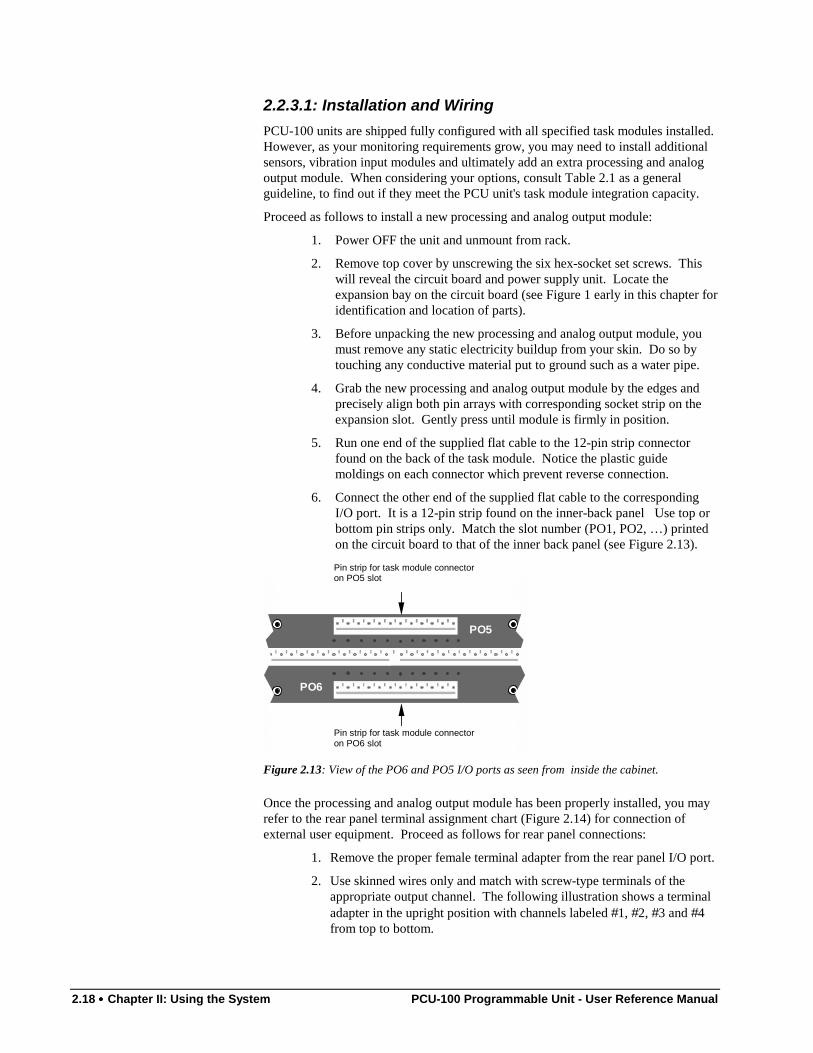
6. Connect the other end of the supplied flat cable to the correspondingI/O port. It is a 12-pin strip found on the inner-back panel Use top orbottom pin strips only. Match the slot number (PO1, PO2, …) printedon the circuit board to that of the inner back panel (see Figure 2.13).
PO5
PO6
Pin strip for task module connectoron PO5 slot
Pin strip for task module connectoron PO6 slot
Figure 2.13: View of the PO6 and PO5 I/O ports as seen from inside the cabinet.
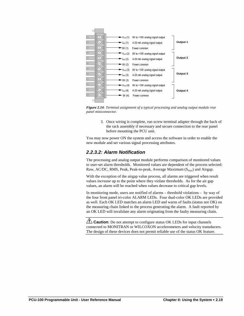
Once the processing and analog output module has been properly installed, you mayrefer to the rear panel terminal assignment chart (Figure 2.14) for connection ofexternal user equipment. Proceed as follows for rear panel connections:
1. Remove the proper female terminal adapter from the rear panel I/O port.
2. Use skinned wires only and match with screw-type terminals of theappropriate output channel. The following illustration shows a terminaladapter in the upright position with channels labeled #1, #2, #3 and #4from top to bottom.
PCU-100 Programmable Unit - User Reference Manual Chapter II: Using the System •••• 2.19
Iout (1) 4-20 mA analog signal output
Iout (4) 4-20 mA analog signal output
Vout (4) 0V to +10V analog signal output
0V (3) Power common
Iout (3) 4-20 mA analog signal output
Vout (3) 0V to +10V analog signal output
0V (2) Power common
Iout (2) 4-20 mA analog signal output
Vout (2) 0V to +10V analog signal output
0V (1) Power common
Vout (1) 0V to +10V analog signal output
0V (4) Power common
Output 1
Output 2
Output 3
Output 4
Figure 2.14: Terminal assignment of a typical processing and analog output module rearpanel miniconnector.
3. Once wiring is complete, run screw terminal adapter through the back ofthe rack assembly if necessary and secure connection to the rear panelbefore mounting the PCU unit.
You may now power ON the system and access the software in order to enable thenew module and set various signal processing attributes.
2.2.3.2: Alarm NotificationThe processing and analog output module performs comparison of monitored valuesto user-set alarm thresholds. Monitored values are dependent of the process selected:Raw, AC/DC, RMS, Peak, Peak-to-peak, Average Maximum (Smax) and Airgap.
With the exception of the airgap value process, all alarms are triggered when resultvalues increase up to the point where they violate thresholds. As for the air gapvalues, an alarm will be reached when values decrease to critical gap levels.
In monitoring mode, users are notified of alarms – threshold violations – by way ofthe four front panel tri-color ALARM LEDs. Four dual-color OK LEDs are providedas well. Each OK LED matches an alarm LED and warns of faults (status not OK) onthe measuring chain linked to the process generating the alarm. A fault reported byan OK LED will invalidate any alarm originating from the faulty measuring chain.
Caution: Do not attempt to configure status OK LEDs for input channelsconnected to MONITRAN or WILCOXON accelerometers and velocity transducers.The design of these devices does not permit reliable use of the status OK feature.
2.20 •••• Chapter II: Using the System PCU-100 Programmable Unit - User Reference Manual
The software typically assigns two alarm thresholds – Alert and Danger – perprocessed signal at one time. Thresholds are usually programmed in the systembefore unit shipment and are reported as follows:
• Alarm LEDs remain ON at all times. They glow Green for as long asreadings remain in the "safe" area of the measuring range.
• Alarm LEDs turn Orange if output values equal or exceed the loweralarm threshold (Alert) set via the PCU software.
• Alarm LEDs turn Red if output values reach the higher alarmthreshold (or Danger level) set via the PCU software.
• OK LEDs remain ON at all times. They shine Green for as long as nofailure of the measuring chain is reported.
• OK LEDs turn Red if measuring chains fail. An example of this wouldbe a broken extension cable. Such an indication would invalidate alarmconditions reported simultaneously by the associated alarm LEDs.
As discussed on page 2.30, a digital input can be assigned to remote thresholdselection, a feature which allows users to toggle between two threshold sets.
Notice to Users of the ZOOM system
PCU-100 units connected to the ZOOM monitoring system through RS-485communication behave like STATE extensions. Therefore, when registeringthe new inputs in your station configuration, set the alarm threshold valuesusing ZOOM Configuration’s Edit input window. Alarm threshold values areprinted in the Configuration Report issued for each PCU-100 unit shipped.Alarm threshold values can also be displayed on the VFD screen when thePCU-100 is in monitoring mode. To view these values, simply toggle betweenbargraph headers using the U and V scroll buttons. See paragraph 3.1.11:Bargraph and Alarm Acknowledgement, to learn how to consult bargraph headers.
The PCU unit complements your annunciation system or other active safety measuresby managing device switching upon alarms reported on any or all of the raw orprocessed data channels. For that purpose, two types of relay modules are available.Relay modules will be discussed further in the next two paragraphs.
PCU-100 Programmable Unit - User Reference Manual Chapter II: Using the System •••• 2.21
2.2.4: The Internal Relay ModuleAs the name implies, the internal relay module is a typical task module which fits anyavailable expansion slot. This module features three miniature dry-contact double-pole-single-throw (DPST) relays for safety device control on any combination ofalarm and OK signals.
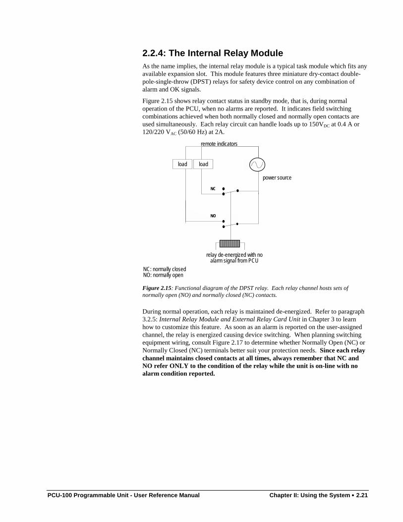
Figure 2.15 shows relay contact status in standby mode, that is, during normaloperation of the PCU, when no alarms are reported. It indicates field switchingcombinations achieved when both normally closed and normally open contacts areused simultaneously. Each relay circuit can handle loads up to 150VDC at 0.4 A or120/220 VAC (50/60 Hz) at 2A.
power source
remote indicators
relay de-energized with noalarm signal from PCU
NC: normally closedNO: normally open
loadload
NC
NO
Figure 2.15: Functional diagram of the DPST relay. Each relay channel hosts sets ofnormally open (NO) and normally closed (NC) contacts.
During normal operation, each relay is maintained de-energized. Refer to paragraph3.2.5: Internal Relay Module and External Relay Card Unit in Chapter 3 to learnhow to customize this feature. As soon as an alarm is reported on the user-assignedchannel, the relay is energized causing device switching. When planning switchingequipment wiring, consult Figure 2.17 to determine whether Normally Open (NC) orNormally Closed (NC) terminals better suit your protection needs. Since each relaychannel maintains closed contacts at all times, always remember that NC andNO refer ONLY to the condition of the relay while the unit is on-line with noalarm condition reported.
2.22 •••• Chapter II: Using the System PCU-100 Programmable Unit - User Reference Manual
2.2.4.1: Installation and WiringPCU-100 units are shipped fully configured with all specified task modules installed.However your system can be easily upgraded for basic machine protection byinstalling an internal relay module. When assessing your protection needs, consultTable 2.1 to find out if they meet the PCU unit's task module integration capacity.
Proceed as follows to install the new internal relay module:
1. Power OFF the unit and unmount from rack.
2. Remove top cover by unscrewing the six hex-socket set screws. Locatethe expansion bay on the circuit board (see Figure 1 early in thischapter for identification and location of parts).
3. Before unpacking the new internal relay module, you must remove anystatic electricity buildup from your skin. Do so by touching anyconductive material put to ground such as a water pipe.
4. Grab the new task module by the edges and precisely align both pinarrays with corresponding socket strip on the expansion slot. Gentlypress until module is firmly in position.
5. Run one end of the supplied flat cable to the 12-pin strip connectorfound on the back of the task module. Notice the plastic guidemoldings on each connector which prevent reverse connection.
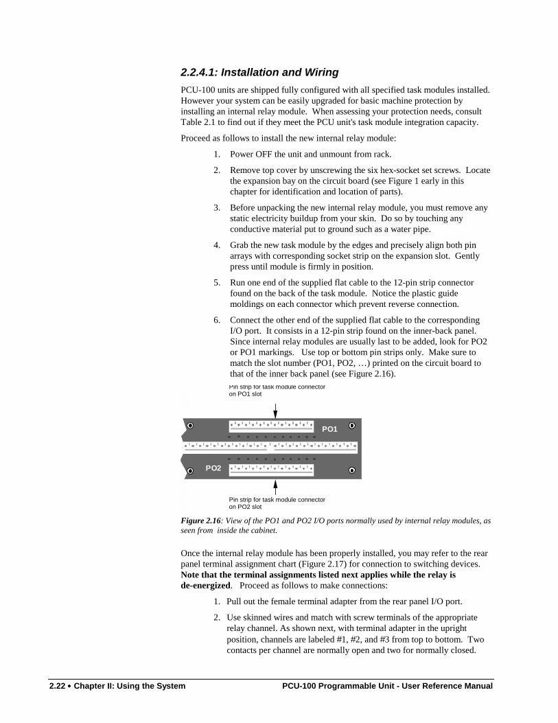
6. Connect the other end of the supplied flat cable to the correspondingI/O port. It consists in a 12-pin strip found on the inner-back panel.Since internal relay modules are usually last to be added, look for PO2or PO1 markings. Use top or bottom pin strips only. Make sure tomatch the slot number (PO1, PO2, …) printed on the circuit board tothat of the inner back panel (see Figure 2.16).
PO1
PO2
Pin strip for task module connectoron PO1 slot
Pin strip for task module connectoron PO2 slot
Figure 2.16: View of the PO1 and PO2 I/O ports normally used by internal relay modules, asseen from inside the cabinet.
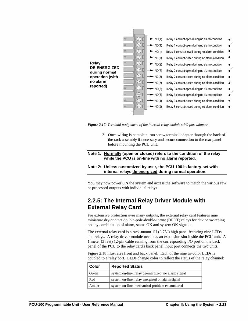
Once the internal relay module has been properly installed, you may refer to the rearpanel terminal assignment chart (Figure 2.17) for connection to switching devices.Note that the terminal assignments listed next applies while the relay isde-energized. Proceed as follows to make connections:
1. Pull out the female terminal adapter from the rear panel I/O port.
2. Use skinned wires and match with screw terminals of the appropriaterelay channel. As shown next, with terminal adapter in the uprightposition, channels are labeled #1, #2, and #3 from top to bottom. Twocontacts per channel are normally open and two for normally closed.
PCU-100 Programmable Unit - User Reference Manual Chapter II: Using the System •••• 2.23
NO(2) Relay 2 contact open during no alarm condition
NC(1) Relay 1 contact closed during no alarm condition
NO(1) Relay 1 contact open during no alarm condition
NC(3) Relay 3 contact closed during no alarm condition
NO(3) Relay 3 contact open during no alarm condition
NO(3) Relay 3 contact open during no alarm condition
NC(2) Relay 2 contact closed during no alarm condition
NC(2) Relay 2 contact closed during no alarm condition
NO(2) Relay 2 contact open during no alarm condition
NC(1) Relay 1 contact closed during no alarm condition
NO(1) Relay 1 contact open during no alarm condition
NC(3) Relay 3 contact closed during no alarm condition
RelayDE-ENERGIZEDduring normaloperation (withno alarmreported)
Figure 2.17: Terminal assignment of the internal relay module's I/O port adapter.
3. Once wiring is complete, run screw terminal adapter through the back ofthe rack assembly if necessary and secure connection to the rear panelbefore mounting the PCU unit.
Note 1: Normally (open or closed) refers to the condition of the relaywhile the PCU is on-line with no alarm reported.
Note 2: Unless customized by user, the PCU-100 is factory-set withinternal relays de-energized during normal operation.
You may now power ON the system and access the software to match the various rawor processed outputs with individual relays.
2.2.5: The Internal Relay Driver Module withExternal Relay CardFor extensive protection over many outputs, the external relay card features nineminiature dry-contact double-pole-double-throw (DPDT) relays for device switchingon any combination of alarm, status OK and system OK signals.
The external relay card is a rack-mount 1U (3.75") high panel featuring nine LEDsand relays. A relay driver module occupies an expansion slot inside the PCU unit. A1 meter (3 feet) 12-pin cable running from the corresponding I/O port on the backpanel of the PCU to the relay card's back panel input port connects the two units.
Figure 2.18 illustrates front and back panel. Each of the nine tri-color LEDs iscoupled to a relay port. LEDs change color to reflect the status of the relay channel:
Color Reported Status
Green system on-line, relay de-energized, no alarm signal
Red system on-line, relay energized on alarm signal
Amber system on-line, mechanical problem encountered
2.24 •••• Chapter II: Using the System PCU-100 Programmable Unit - User Reference Manual
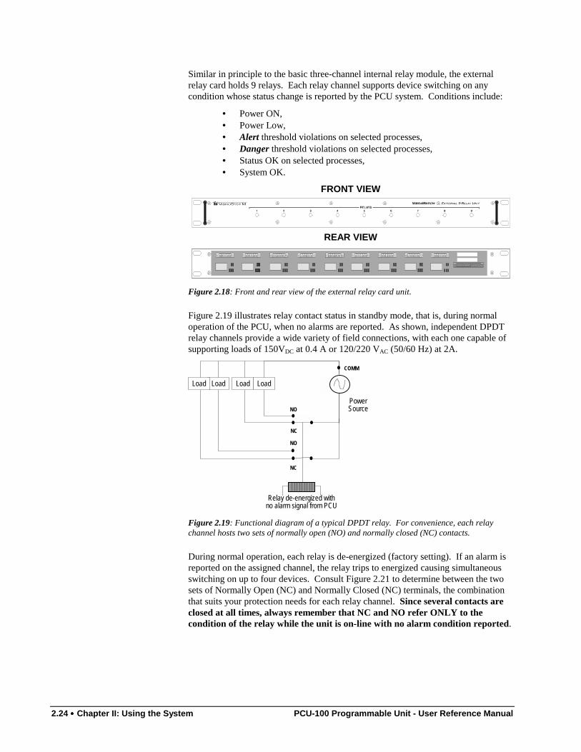
Similar in principle to the basic three-channel internal relay module, the externalrelay card holds 9 relays. Each relay channel supports device switching on anycondition whose status change is reported by the PCU system. Conditions include:
• Power ON,• Power Low,• Alert threshold violations on selected processes,• Danger threshold violations on selected processes,• Status OK on selected processes,• System OK.
FRONT VIEW
REAR VIEW
Figure 2.18: Front and rear view of the external relay card unit.
Figure 2.19 illustrates relay contact status in standby mode, that is, during normaloperation of the PCU, when no alarms are reported. As shown, independent DPDTrelay channels provide a wide variety of field connections, with each one capable ofsupporting loads of 150VDC at 0.4 A or 120/220 VAC (50/60 Hz) at 2A.
PowerSource
Relay de-energized withno alarm signal from PCU
NC
NC
NO
NO
COMM
LoadLoadLoadLoad
Figure 2.19: Functional diagram of a typical DPDT relay. For convenience, each relaychannel hosts two sets of normally open (NO) and normally closed (NC) contacts.
During normal operation, each relay is de-energized (factory setting). If an alarm isreported on the assigned channel, the relay trips to energized causing simultaneousswitching on up to four devices. Consult Figure 2.21 to determine between the twosets of Normally Open (NC) and Normally Closed (NC) terminals, the combinationthat suits your protection needs for each relay channel. Since several contacts areclosed at all times, always remember that NC and NO refer ONLY to thecondition of the relay while the unit is on-line with no alarm condition reported.
PCU-100 Programmable Unit - User Reference Manual Chapter II: Using the System •••• 2.25
2.2.5.1: Installation and WiringPCU-100 units are shipped fully configured with all specified task modules installed.However if your installation requires extensive protection, you may upgrade to fullrelay capacity by installing an internal relay driver module with external relay cardunit. When assessing your protection needs, consult Table 2.1 to find out if theymeet the PCU unit's task module integration capacity.
Installation of the task module and external card unit is done in three steps. First, theinternal relay driver module must be installed inside the PCU unit; which is thenconnected to the external relay card unit and finally field (user) equipment must bewired to the external relay card unit's back panel I/O port.
Step One:
Proceed as follows to install the internal relay driver module:
1. Power OFF the PCU unit and unmount from rack.
2. Remove top cover by unscrewing the six hex-socket set screws. Thiswill reveal the circuit board and power supply unit. Locate theexpansion bay on the circuit board (see Figure 1 early in this chapter foridentification and location of parts).
3. Before unpacking the new internal relay driver module, you mustremove any static electricity buildup from your skin. Do so by touchingany conductive material put to ground such as a water pipe.
4. Grab the internal relay driver module by the edges and precisely alignboth pin arrays with corresponding socket strip on the expansion slot.Gently press until module is firmly in position.
5. Run one end of the supplied flat cable to the 12-pin strip connectorfound on the back of the task module. Notice the plastic guidemoldings on each connector which prevent reverse connection.
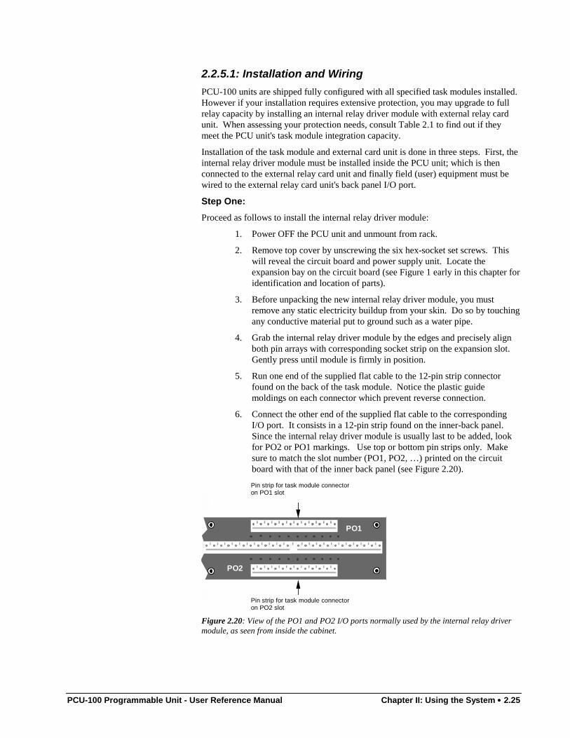
6. Connect the other end of the supplied flat cable to the correspondingI/O port. It consists in a 12-pin strip found on the inner-back panel.Since the internal relay driver module is usually last to be added, lookfor PO2 or PO1 markings. Use top or bottom pin strips only. Makesure to match the slot number (PO1, PO2, …) printed on the circuitboard with that of the inner back panel (see Figure 2.20).
PO1
PO2
Pin strip for task module connectoron PO1 slot
Pin strip for task module connectoron PO2 slot
Figure 2.20: View of the PO1 and PO2 I/O ports normally used by the internal relay drivermodule, as seen from inside the cabinet.
2.26 •••• Chapter II: Using the System PCU-100 Programmable Unit - User Reference Manual
Step Two:
1. Once you have properly installed the internal relay driver module, youmay proceed with connection to the external relay card unit. To do so:simply grab the interface cord and connect one end to the designatedI/O port on the PCU-100 unit.
2. Connect the other end of the interface cord to the input port connectorlocated on the extreme right of the relay unit's back panel.
Step Three:
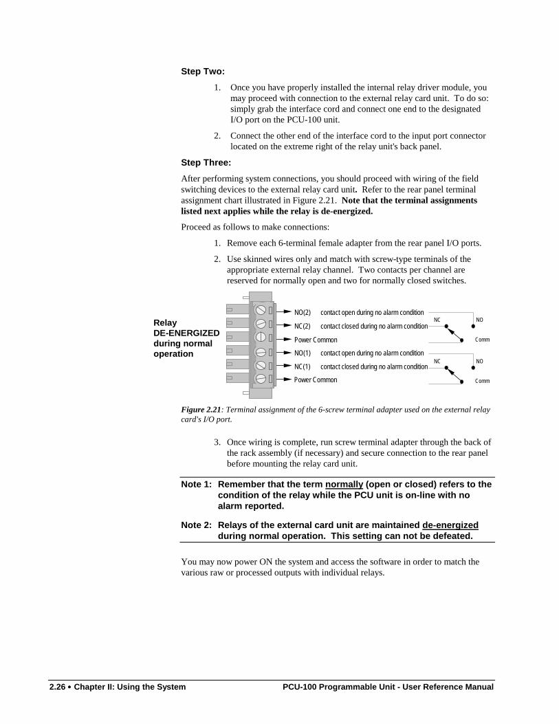
After performing system connections, you should proceed with wiring of the fieldswitching devices to the external relay card unit. Refer to the rear panel terminalassignment chart illustrated in Figure 2.21. Note that the terminal assignmentslisted next applies while the relay is de-energized.
Proceed as follows to make connections:
1. Remove each 6-terminal female adapter from the rear panel I/O ports.
2. Use skinned wires only and match with screw-type terminals of theappropriate external relay channel. Two contacts per channel arereserved for normally open and two for normally closed switches.
NC(1) contact closed during no alarm condition
NO(1) contact open during no alarm condition
Power Common
NC(2) contact closed during no alarm condition
NO(2) contact open during no alarm condition
Power Common
NO
Comm
NO
Comm
NC
NCRelayDE-ENERGIZEDduring normaloperation
Figure 2.21: Terminal assignment of the 6-screw terminal adapter used on the external relaycard's I/O port.
3. Once wiring is complete, run screw terminal adapter through the back ofthe rack assembly (if necessary) and secure connection to the rear panelbefore mounting the relay card unit.
Note 1: Remember that the term normally (open or closed) refers to thecondition of the relay while the PCU unit is on-line with noalarm reported.
Note 2: Relays of the external card unit are maintained de-energizedduring normal operation. This setting can not be defeated.
You may now power ON the system and access the software in order to match thevarious raw or processed outputs with individual relays.
PCU-100 Programmable Unit - User Reference Manual Chapter II: Using the System •••• 2.27
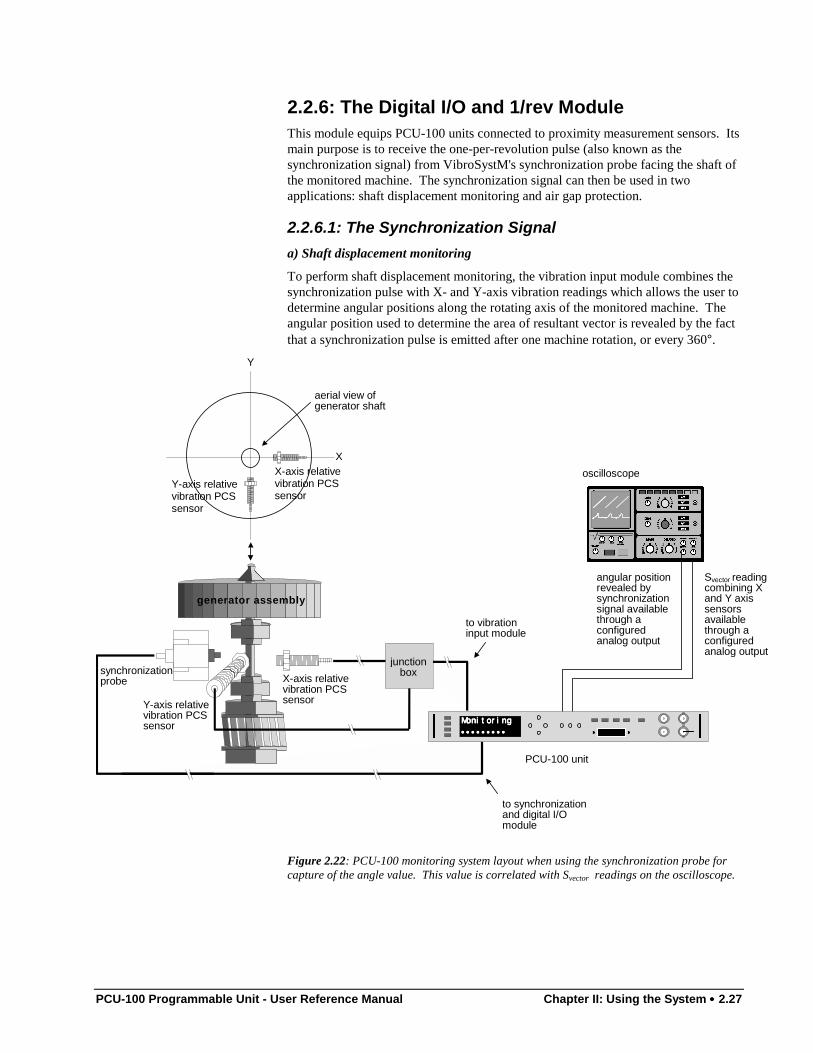
2.2.6: The Digital I/O and 1/rev ModuleThis module equips PCU-100 units connected to proximity measurement sensors. Itsmain purpose is to receive the one-per-revolution pulse (also known as thesynchronization signal) from VibroSystM's synchronization probe facing the shaft ofthe monitored machine. The synchronization signal can then be used in twoapplications: shaft displacement monitoring and air gap protection.
2.2.6.1: The Synchronization Signala) Shaft displacement monitoring
To perform shaft displacement monitoring, the vibration input module combines thesynchronization pulse with X- and Y-axis vibration readings which allows the user todetermine angular positions along the rotating axis of the monitored machine. Theangular position used to determine the area of resultant vector is revealed by the factthat a synchronization pulse is emitted after one machine rotation, or every 360°.
MonitoringMonitoringMonitoringMonitoring
••••••••••••••••••••••••••••••••••••
X-axis relativevibration PCSsensor
aerial view ofgenerator shaft
synchronizationprobe X-axis relative
vibration PCSsensorY-axis relative
vibration PCSsensor
PCU-100 unit
oscilloscope
junctionbox
generator assembly
angular positionrevealed bysynchronizationsignal availablethrough aconfiguredanalog output
Svector readingcombining Xand Y axissensorsavailablethrough aconfiguredanalog output
Y-axis relativevibration PCSsensor
X
Y
to vibrationinput module
to synchronizationand digital I/Omodule
Figure 2.22: PCU-100 monitoring system layout when using the synchronization probe forcapture of the angle value. This value is correlated with Svector readings on the oscilloscope.
2.28 •••• Chapter II: Using the System PCU-100 Programmable Unit - User Reference Manual
Figure 2.22 shows PCS sensor position and signal paths to user equipment such as anoscilloscope. The graphs plotted in Figure 2.23 are typical of those displayed on anoscilloscope screen. They illustrate the information provided simultaneously by thesynchronization probe (Graph A) and two PCS sensors used for the measurement ofgenerator shaft displacement (Graph B). For this purpose, individual sensorsconnected to input channel 1 and input channel 2 of the vibration input module facethe generator shaft at X and Y positions relative to each other (see Figure 2.22).
Note: This application requires that you access the configuration software to assignanalog outputs to the 1/REV pulse and Svector signals and that you connect youroscilloscope to the matching rear-panel I/O port. See paragraph 3.2.3 for more onassigning analog outputs.
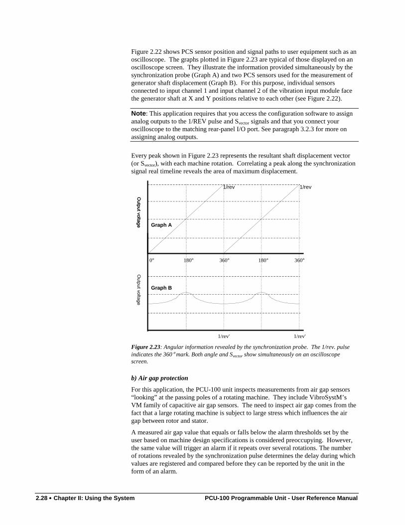
Every peak shown in Figure 2.23 represents the resultant shaft displacement vector(or Svector), with each machine rotation. Correlating a peak along the synchronizationsignal real timeline reveals the area of maximum displacement.
360°
1/rev 1/rev
360°180° 180°0°
Graph A
Graph B
1/rev' 1/rev'
Figure 2.23: Angular information revealed by the synchronization probe. The 1/rev. pulseindicates the 360° mark. Both angle and Svector show simultaneously on an oscilloscopescreen.
b) Air gap protection
For this application, the PCU-100 unit inspects measurements from air gap sensors“looking” at the passing poles of a rotating machine. They include VibroSystM’sVM family of capacitive air gap sensors. The need to inspect air gap comes from thefact that a large rotating machine is subject to large stress which influences the airgap between rotor and stator.
A measured air gap value that equals or falls below the alarm thresholds set by theuser based on machine design specifications is considered preoccupying. However,the same value will trigger an alarm if it repeats over several rotations. The numberof rotations revealed by the synchronization pulse determines the delay during whichvalues are registered and compared before they can be reported by the unit in theform of an alarm.
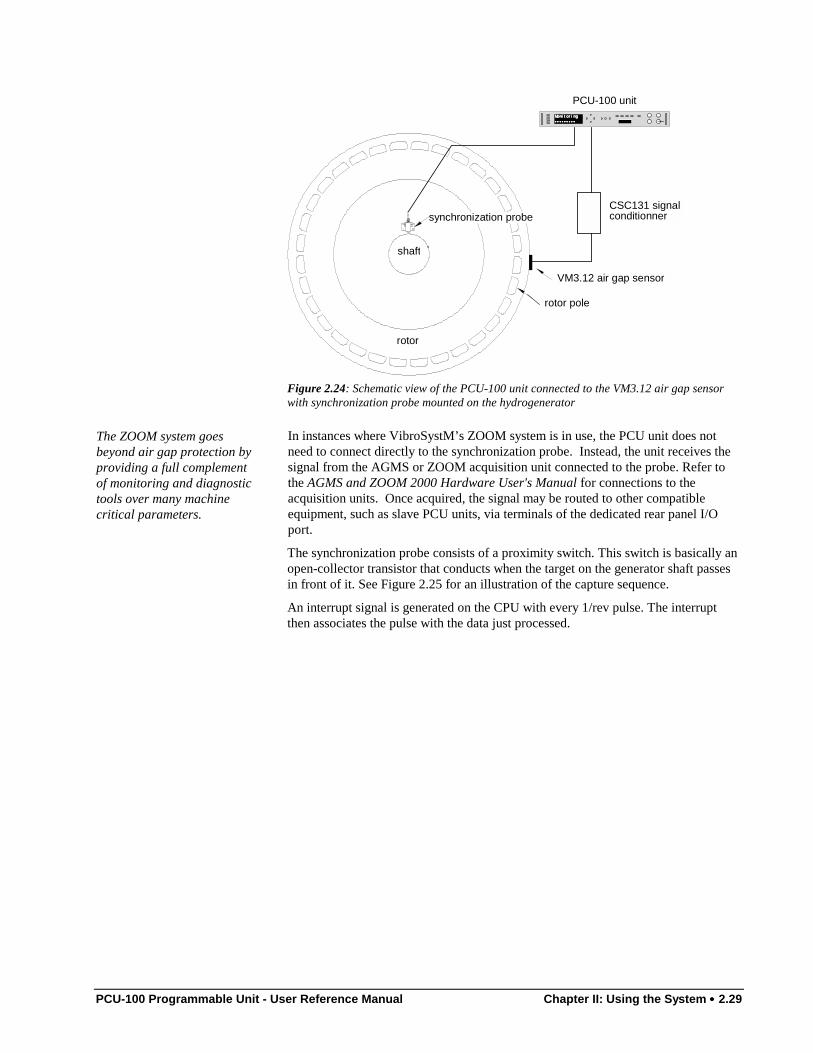
PCU-100 Programmable Unit - User Reference Manual Chapter II: Using the System •••• 2.29
MonitoringMonitoringMonitoringMonitoring
••••••••••••••••••••••••••••••••••••
synchronization probeCSC131 signalconditionner
VM3.12 air gap sensor
PCU-100 unit
shaft
rotor
rotor pole
Figure 2.24: Schematic view of the PCU-100 unit connected to the VM3.12 air gap sensorwith synchronization probe mounted on the hydrogenerator
The ZOOM system goesbeyond air gap protection byproviding a full complementof monitoring and diagnostictools over many machinecritical parameters.
In instances where VibroSystM’s ZOOM system is in use, the PCU unit does notneed to connect directly to the synchronization probe. Instead, the unit receives thesignal from the AGMS or ZOOM acquisition unit connected to the probe. Refer tothe AGMS and ZOOM 2000 Hardware User's Manual for connections to theacquisition units. Once acquired, the signal may be routed to other compatibleequipment, such as slave PCU units, via terminals of the dedicated rear panel I/Oport.
The synchronization probe consists of a proximity switch. This switch is basically anopen-collector transistor that conducts when the target on the generator shaft passesin front of it. See Figure 2.25 for an illustration of the capture sequence.
An interrupt signal is generated on the CPU with every 1/rev pulse. The interruptthen associates the pulse with the data just processed.
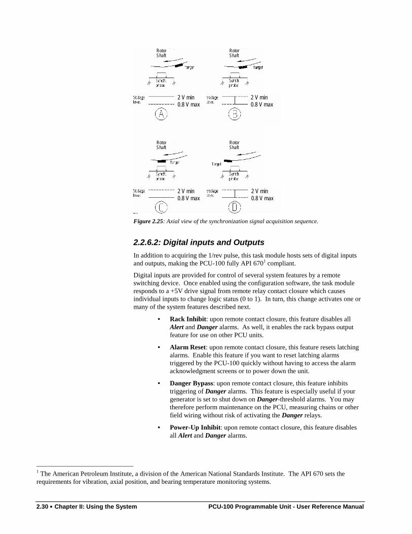
2.30 •••• Chapter II: Using the System PCU-100 Programmable Unit - User Reference Manual
2 V min0.8 V max
2 V min0.8 V max
2 V min0.8 V max
2 V min0.8 V max
RotorShaft
RotorShaft
RotorShaft
RotorShaft
Figure 2.25: Axial view of the synchronization signal acquisition sequence.
2.2.6.2: Digital inputs and OutputsIn addition to acquiring the 1/rev pulse, this task module hosts sets of digital inputsand outputs, making the PCU-100 fully API 6701 compliant.
Digital inputs are provided for control of several system features by a remoteswitching device. Once enabled using the configuration software, the task moduleresponds to a +5V drive signal from remote relay contact closure which causesindividual inputs to change logic status (0 to 1). In turn, this change activates one ormany of the system features described next.
• Rack Inhibit: upon remote contact closure, this feature disables allAlert and Danger alarms. As well, it enables the rack bypass outputfeature for use on other PCU units.
• Alarm Reset: upon remote contact closure, this feature resets latchingalarms. Enable this feature if you want to reset latching alarmstriggered by the PCU-100 quickly without having to access the alarmacknowledgment screens or to power down the unit.
• Danger Bypass: upon remote contact closure, this feature inhibitstriggering of Danger alarms. This feature is especially useful if yourgenerator is set to shut down on Danger-threshold alarms. You maytherefore perform maintenance on the PCU, measuring chains or otherfield wiring without risk of activating the Danger relays.
• Power-Up Inhibit: upon remote contact closure, this feature disablesall Alert and Danger alarms.
1 The American Petroleum Institute, a division of the American National Standards Institute. The API 670 sets therequirements for vibration, axial position, and bearing temperature monitoring systems.
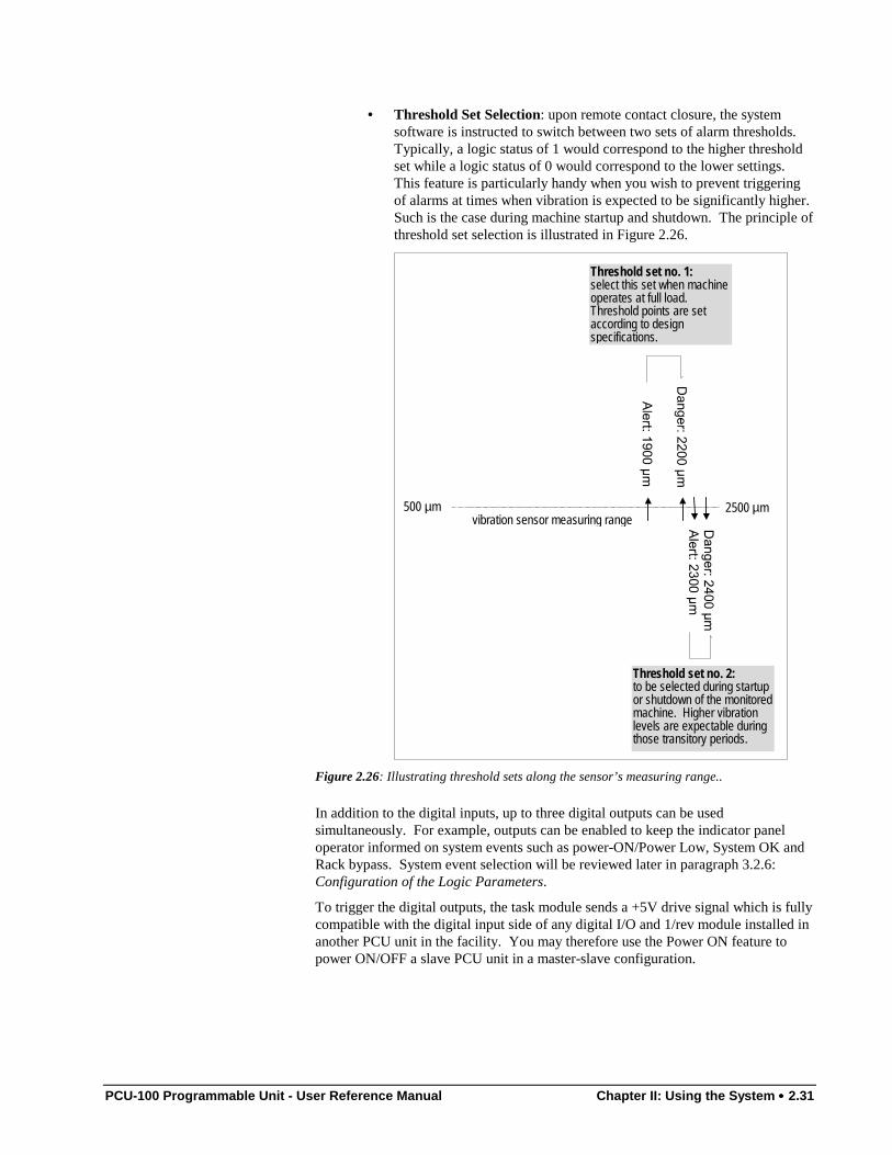
PCU-100 Programmable Unit - User Reference Manual Chapter II: Using the System •••• 2.31
• Threshold Set Selection: upon remote contact closure, the systemsoftware is instructed to switch between two sets of alarm thresholds.Typically, a logic status of 1 would correspond to the higher thresholdset while a logic status of 0 would correspond to the lower settings.This feature is particularly handy when you wish to prevent triggeringof alarms at times when vibration is expected to be significantly higher.Such is the case during machine startup and shutdown. The principle ofthreshold set selection is illustrated in Figure 2.26.
500 µm 2500 µmvibration sensor measuring range
Threshold set no. 2:to be selected during startupor shutdown of the monitoredmachine. Higher vibrationlevels are expectable duringthose transitory periods.
Threshold set no. 1:select this set when machineoperates at full load.Threshold points are setaccording to designspecifications.
Figure 2.26: Illustrating threshold sets along the sensor’s measuring range..
In addition to the digital inputs, up to three digital outputs can be usedsimultaneously. For example, outputs can be enabled to keep the indicator paneloperator informed on system events such as power-ON/Power Low, System OK andRack bypass. System event selection will be reviewed later in paragraph 3.2.6:Configuration of the Logic Parameters.
To trigger the digital outputs, the task module sends a +5V drive signal which is fullycompatible with the digital input side of any digital I/O and 1/rev module installed inanother PCU unit in the facility. You may therefore use the Power ON feature topower ON/OFF a slave PCU unit in a master-slave configuration.
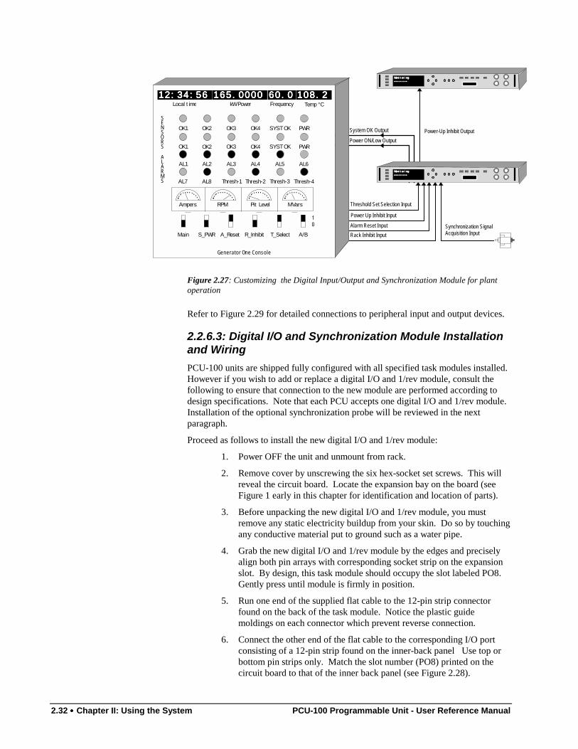
2.32 •••• Chapter II: Using the System PCU-100 Programmable Unit - User Reference Manual
Threshold Set Selection Input
Power Up Inhibit Input
Alarm Reset Input
Rack Inhibit Input
Power ON/Low Output
System OK Output Power-Up Inhibit OutputOK1 OK2 OK3 OK4 SYST OK PWR
OK1 OK2 OK3 OK4 SYST OK PWR
AL1 AL2 AL3 AL4 AL5 AL6
AL7 AL8 Thresh-1 Thresh-2 Thresh-3 Thresh-4
Local t ime kW Power Frequency
10
Generator One Console
S_PWR
Temp °C
Main A_Reset R_Inhibit T_Select A/B
SENSORS
ALARMS
Ampers
12:34:5612:34:5612:34:5612:34:56 165.0000165.0000165.0000165.0000 60.060.060.060.0 108.2108.2108.2108.2
RPM Pit Level MVars
MonitoringMonitoringMonitoringMonitoring
••••••••••••••••••••••••••••••••••••
MonitoringMonitoringMonitoringMonitoring
••••••••••••••••••••••••••••••••••••
Synchronization SignalAcquisition Input
Figure 2.27: Customizing the Digital Input/Output and Synchronization Module for plantoperation
Refer to Figure 2.29 for detailed connections to peripheral input and output devices.
2.2.6.3: Digital I/O and Synchronization Module Installationand WiringPCU-100 units are shipped fully configured with all specified task modules installed.However if you wish to add or replace a digital I/O and 1/rev module, consult thefollowing to ensure that connection to the new module are performed according todesign specifications. Note that each PCU accepts one digital I/O and 1/rev module.Installation of the optional synchronization probe will be reviewed in the nextparagraph.
Proceed as follows to install the new digital I/O and 1/rev module:
1. Power OFF the unit and unmount from rack.
2. Remove cover by unscrewing the six hex-socket set screws. This willreveal the circuit board. Locate the expansion bay on the board (seeFigure 1 early in this chapter for identification and location of parts).
3. Before unpacking the new digital I/O and 1/rev module, you mustremove any static electricity buildup from your skin. Do so by touchingany conductive material put to ground such as a water pipe.
4. Grab the new digital I/O and 1/rev module by the edges and preciselyalign both pin arrays with corresponding socket strip on the expansionslot. By design, this task module should occupy the slot labeled PO8.Gently press until module is firmly in position.
5. Run one end of the supplied flat cable to the 12-pin strip connectorfound on the back of the task module. Notice the plastic guidemoldings on each connector which prevent reverse connection.
6. Connect the other end of the flat cable to the corresponding I/O portconsisting of a 12-pin strip found on the inner-back panel Use top orbottom pin strips only. Match the slot number (PO8) printed on thecircuit board to that of the inner back panel (see Figure 2.28).
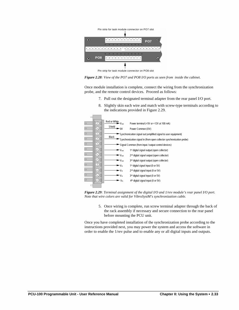
PCU-100 Programmable Unit - User Reference Manual Chapter II: Using the System •••• 2.33
PO7
PO8
Pin strip for task module connector on PO7 slot
Pin strip for task module connector on PO8 slot
Figure 2.28: View of the PO7 and PO8 I/O ports as seen from inside the cabinet.
Once module installation is complete, connect the wiring from the synchronizationprobe, and the remote control devices. Proceed as follows:
7. Pull out the designated terminal adapter from the rear panel I/O port.
8. Slightly skin each wire and match with screw-type terminals according tothe indications provided in Figure 2.29.
Vout 3rd digital signal output (open collector)
Signal Common (from input / output control devices)
Synchronization signal out (amplified signal to user equipment)
Synchronization signal in (from open collector synchronization probe)
Vout Power terminal (+5V or +12V at 100 mA)
0V Power Common (OV)
Vin 3rd digital signal input (0 or 5V)
Vin 2nd digital signal input (0 or 5V)
Vin 1st digital signal input (0 or 5V)
Vout 2nd digital signal output (open collector)
Vout 1st digital signal output (open collector)
Vin 4th digital signal input (0 or 5V)
Red or White
Shield
Black
Figure 2.29: Terminal assignment of the digital I/O and 1/rev module’s rear panel I/O port.Note that wire colors are valid for VibroSystM’s synchronization cable.
5. Once wiring is complete, run screw terminal adapter through the back ofthe rack assembly if necessary and secure connection to the rear panelbefore mounting the PCU unit.
Once you have completed installation of the synchronization probe according to theinstructions provided next, you may power the system and access the software inorder to enable the 1/rev pulse and to enable any or all digital inputs and outputs.
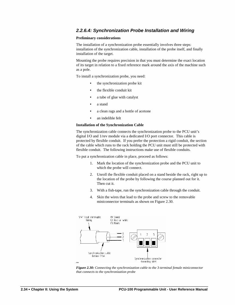
2.34 •••• Chapter II: Using the System PCU-100 Programmable Unit - User Reference Manual
2.2.6.4: Synchronization Probe Installation and WiringPreliminary considerations
The installation of a synchronization probe essentially involves three steps:installation of the synchronization cable, installation of the probe itself, and finallyinstallation of the target.
Mounting the probe requires precision in that you must determine the exact locationof its target in relation to a fixed reference mark around the axis of the machine suchas a pole.
To install a synchronization probe, you need:
• the synchronization probe kit
• the flexible conduit kit
• a tube of glue with catalyst
• a stand
• a clean rags and a bottle of acetone
• an indelible felt
Installation of the Synchronization Cable
The synchronization cable connects the synchronization probe to the PCU unit’sdigital I/O and 1/rev module via a dedicated I/O port connector. This cable isprotected by flexible conduit. If you prefer the protection a rigid conduit, the sectionof the cable which runs to the rack holding the PCU unit must still be protected withflexible conduit. The following instructions make use of flexible conduits.
To put a synchronization cable in place, proceed as follows:
1. Mark the location of the synchronization probe and the PCU unit towhich the probe will connect.
2. Unroll the flexible conduit placed on a stand beside the rack, right up tothe location of the probe by following the course planned out for it.Then cut it.
3. With a fish-tape, run the synchronization cable through the conduit.
4. Skin the wires that lead to the probe and screw to the removableminiconnector terminals as shown on Figure 2.30.
Figure 2.30: Connecting the synchronization cable to the 3-terminal female miniconnectorthat connects to the synchronization probe
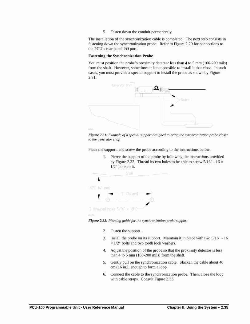
PCU-100 Programmable Unit - User Reference Manual Chapter II: Using the System •••• 2.35
5. Fasten down the conduit permanently.
The installation of the synchronization cable is completed. The next step consists infastening down the synchronization probe. Refer to Figure 2.29 for connections tothe PCU’s rear panel I/O port.
Fastening the Synchronization Probe
You must position the probe’s proximity detector less than 4 to 5 mm (160-200 mils)from the shaft. However, sometimes it is not possible to install it that close. In suchcases, you must provide a special support to install the probe as shown by Figure2.31.
Figure 2.31: Example of a special support designed to bring the synchronization probe closerto the generator shaft
Place the support, and screw the probe according to the instructions below.
1. Pierce the support of the probe by following the instructions providedby Figure 2.32. Thread its two holes to be able to screw 5/16" - 16 ×1/2" bolts to it.
Figure 2.32: Piercing guide for the synchronization probe support
2. Fasten the support.
3. Install the probe on its support. Maintain it in place with two 5/16" - 16× 1/2" bolts and two tooth lock washers.
4. Adjust the position of the probe so that the proximity detector is lessthan 4 to 5 mm (160-200 mils) from the shaft.
5. Gently pull on the synchronization cable. Slacken the cable about 40cm (16 in.), enough to form a loop.
6. Connect the cable to the synchronization probe. Then, close the loopwith cable straps. Consult Figure 2.33.
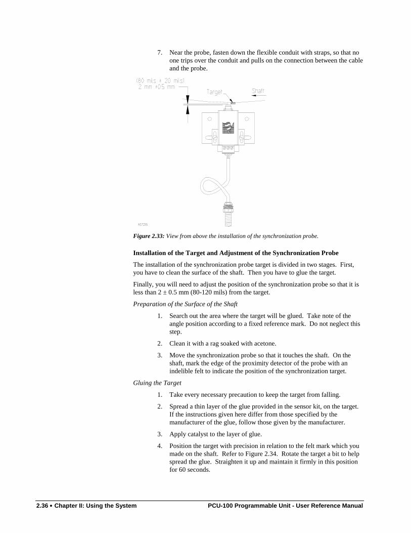
2.36 •••• Chapter II: Using the System PCU-100 Programmable Unit - User Reference Manual
7. Near the probe, fasten down the flexible conduit with straps, so that noone trips over the conduit and pulls on the connection between the cableand the probe.
Figure 2.33: View from above the installation of the synchronization probe.
Installation of the Target and Adjustment of the Synchronization Probe
The installation of the synchronization probe target is divided in two stages. First,you have to clean the surface of the shaft. Then you have to glue the target.
Finally, you will need to adjust the position of the synchronization probe so that it isless than 2 ± 0.5 mm (80-120 mils) from the target.
Preparation of the Surface of the Shaft
1. Search out the area where the target will be glued. Take note of theangle position according to a fixed reference mark. Do not neglect thisstep.
2. Clean it with a rag soaked with acetone.
3. Move the synchronization probe so that it touches the shaft. On theshaft, mark the edge of the proximity detector of the probe with anindelible felt to indicate the position of the synchronization target.
Gluing the Target
1. Take every necessary precaution to keep the target from falling.
2. Spread a thin layer of the glue provided in the sensor kit, on the target.If the instructions given here differ from those specified by themanufacturer of the glue, follow those given by the manufacturer.
3. Apply catalyst to the layer of glue.
4. Position the target with precision in relation to the felt mark which youmade on the shaft. Refer to Figure 2.34. Rotate the target a bit to helpspread the glue. Straighten it up and maintain it firmly in this positionfor 60 seconds.
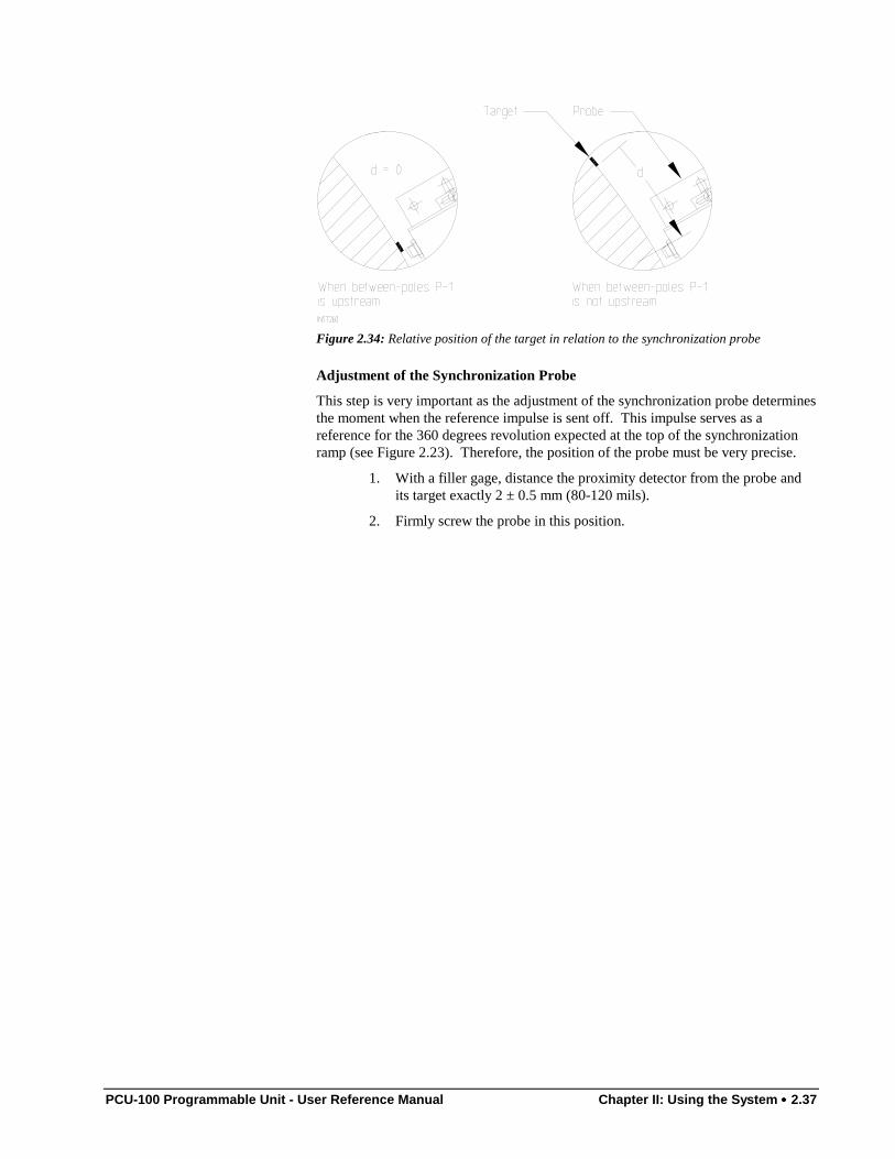
PCU-100 Programmable Unit - User Reference Manual Chapter II: Using the System •••• 2.37
Figure 2.34: Relative position of the target in relation to the synchronization probe
Adjustment of the Synchronization Probe
This step is very important as the adjustment of the synchronization probe determinesthe moment when the reference impulse is sent off. This impulse serves as areference for the 360 degrees revolution expected at the top of the synchronizationramp (see Figure 2.23). Therefore, the position of the probe must be very precise.
1. With a filler gage, distance the proximity detector from the probe andits target exactly 2 ± 0.5 mm (80-120 mils).
2. Firmly screw the probe in this position.
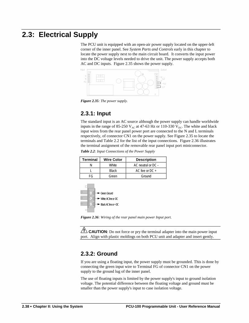
2.38 •••• Chapter II: Using the System PCU-100 Programmable Unit - User Reference Manual
2.3: Electrical SupplyThe PCU unit is equipped with an open-air power supply located on the upper-leftcorner of the inner panel. See System Parts and Controls early in this chapter tolocate the power supply next to the main circuit board. It converts the input powerinto the DC voltage levels needed to drive the unit. The power supply accepts bothAC and DC inputs. Figure 2.35 shows the power supply.
Figure 2.35: The power supply.
2.3.1: InputThe standard input is an AC source although the power supply can handle worldwideinputs in the range of 85-250 VAC at 47-63 Hz or 110-330 VDC. The white and blackinput wires from the rear panel power port are connected to the N and L terminalsrespectively, of connector CN1 on the power supply. See Figure 2.35 to locate theterminals and Table 2.2 for the list of the input connections. Figure 2.36 illustratesthe terminal assignment of the removable rear panel input port miniconnector.Table 2.2: Input Connections of the Power Supply
Terminal Wire Color Description
N White AC neutral or DC -L Black AC live or DC +
FG Green Ground
White: AC line or -DC
Black: AC line or + DC
Green: Ground
Figure 2.36: Wiring of the rear panel main power Input port.
CAUTION: Do not force or pry the terminal adapter into the main power inputport. Align with plastic moldings on both PCU unit and adapter and insert gently.
2.3.2: GroundIf you are using a floating input, the power supply must be grounded. This is done byconnecting the green input wire to Terminal FG of connector CN1 on the powersupply to the ground lug of the inner panel.
The use of floating inputs is limited by the power supply's input to ground isolationvoltage. The potential difference between the floating voltage and ground must besmaller than the power supply's input to case isolation voltage.
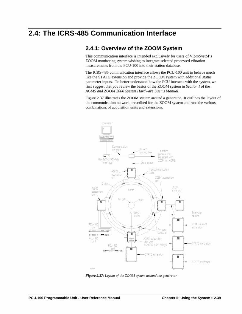
PCU-100 Programmable Unit - User Reference Manual Chapter II: Using the System •••• 2.39
2.4: The ICRS-485 Communication Interface
2.4.1: Overview of the ZOOM SystemThis communication interface is intended exclusively for users of VibroSystM’sZOOM monitoring system wishing to integrate selected processed vibrationmeasurements from the PCU-100 into their station database.
The ICRS-485 communication interface allows the PCU-100 unit to behave muchlike the STATE extension and provide the ZOOM system with additional statusparameter inputs. To better understand how the PCU interacts with the system, wefirst suggest that you review the basics of the ZOOM system in Section I of theAGMS and ZOOM 2000 System Hardware User’s Manual.
Figure 2.37 illustrates the ZOOM system around a generator. It outlines the layout ofthe communication network prescribed for the ZOOM system and runs the variouscombinations of acquisition units and extensions.
Figure 2.37: Layout of the ZOOM system around the generator
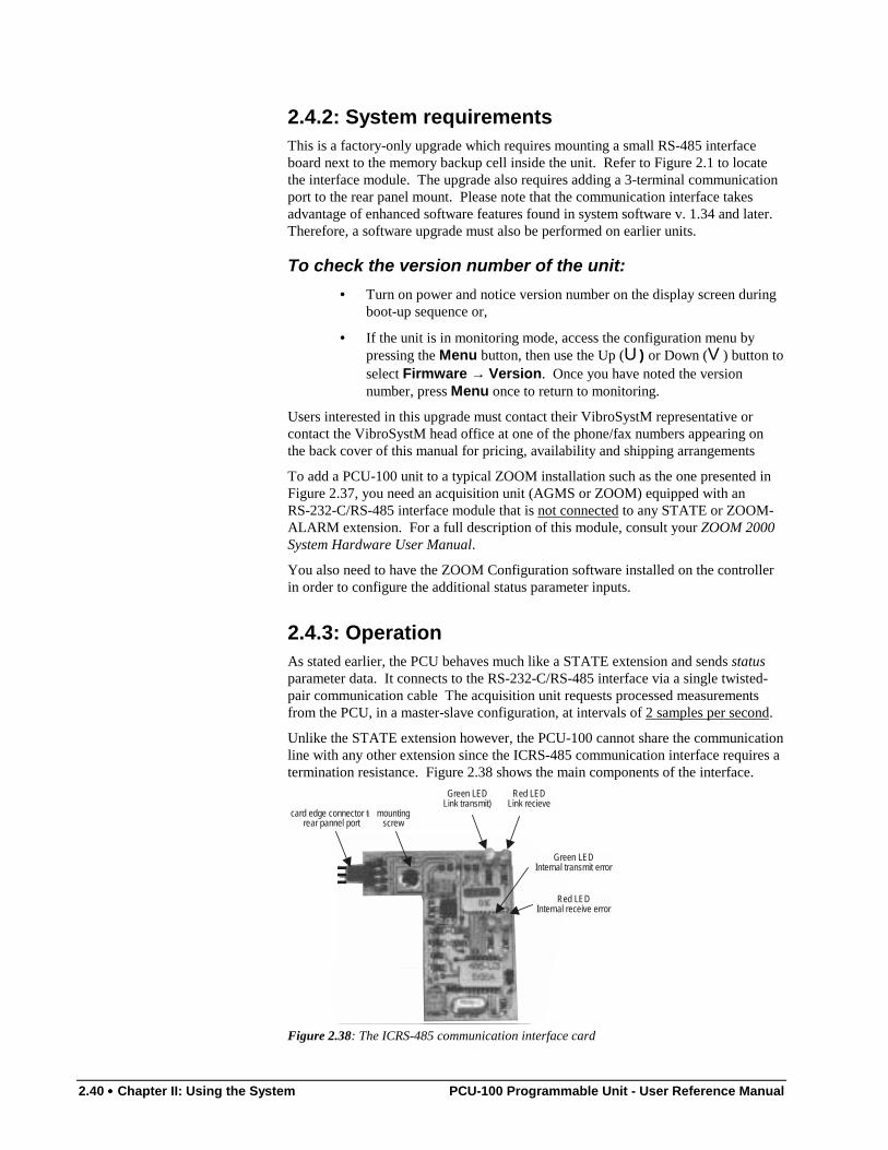
2.40 •••• Chapter II: Using the System PCU-100 Programmable Unit - User Reference Manual
2.4.2: System requirementsThis is a factory-only upgrade which requires mounting a small RS-485 interfaceboard next to the memory backup cell inside the unit. Refer to Figure 2.1 to locatethe interface module. The upgrade also requires adding a 3-terminal communicationport to the rear panel mount. Please note that the communication interface takesadvantage of enhanced software features found in system software v. 1.34 and later.Therefore, a software upgrade must also be performed on earlier units.
To check the version number of the unit:• Turn on power and notice version number on the display screen during
boot-up sequence or,
• If the unit is in monitoring mode, access the configuration menu bypressing the Menu button, then use the Up (U) or Down (V) button toselect Firmware → Version. Once you have noted the versionnumber, press Menu once to return to monitoring.
Users interested in this upgrade must contact their VibroSystM representative orcontact the VibroSystM head office at one of the phone/fax numbers appearing onthe back cover of this manual for pricing, availability and shipping arrangements
To add a PCU-100 unit to a typical ZOOM installation such as the one presented inFigure 2.37, you need an acquisition unit (AGMS or ZOOM) equipped with anRS-232-C/RS-485 interface module that is not connected to any STATE or ZOOM-ALARM extension. For a full description of this module, consult your ZOOM 2000System Hardware User Manual.
You also need to have the ZOOM Configuration software installed on the controllerin order to configure the additional status parameter inputs.
2.4.3: OperationAs stated earlier, the PCU behaves much like a STATE extension and sends statusparameter data. It connects to the RS-232-C/RS-485 interface via a single twisted-pair communication cable The acquisition unit requests processed measurementsfrom the PCU, in a master-slave configuration, at intervals of 2 samples per second.
Unlike the STATE extension however, the PCU-100 cannot share the communicationline with any other extension since the ICRS-485 communication interface requires atermination resistance. Figure 2.38 shows the main components of the interface.
Green LEDLink transmit)
Red LEDLink recieve
Green LEDInternal transmit error
card edge connector torear pannel port
mountingscrew
Red LEDInternal receive error
Figure 2.38: The ICRS-485 communication interface card
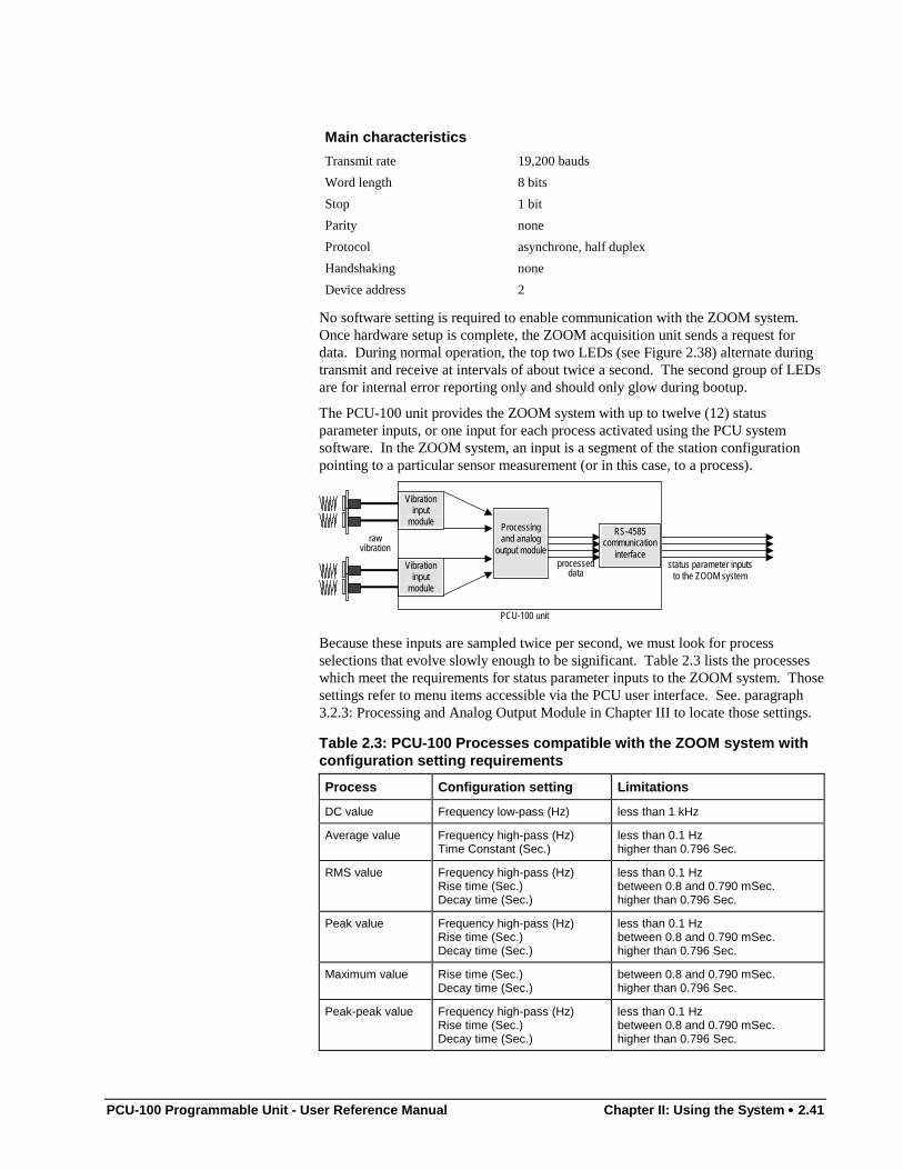
PCU-100 Programmable Unit - User Reference Manual Chapter II: Using the System •••• 2.41
Main characteristics
Transmit rate 19,200 bauds
Word length 8 bits
Stop 1 bit
Parity none
Protocol asynchrone, half duplex
Handshaking none
Device address 2
No software setting is required to enable communication with the ZOOM system.Once hardware setup is complete, the ZOOM acquisition unit sends a request fordata. During normal operation, the top two LEDs (see Figure 2.38) alternate duringtransmit and receive at intervals of about twice a second. The second group of LEDsare for internal error reporting only and should only glow during bootup.
The PCU-100 unit provides the ZOOM system with up to twelve (12) statusparameter inputs, or one input for each process activated using the PCU systemsoftware. In the ZOOM system, an input is a segment of the station configurationpointing to a particular sensor measurement (or in this case, to a process).
Processingand analog
output module
Vibrationinput
module
Vibrationinput
moduleRS-4585
communicationinterface
status parameter inputsto the ZOOM system
processeddata
rawvibration
PCU-100 unit
Because these inputs are sampled twice per second, we must look for processselections that evolve slowly enough to be significant. Table 2.3 lists the processeswhich meet the requirements for status parameter inputs to the ZOOM system. Thosesettings refer to menu items accessible via the PCU user interface. See. paragraph3.2.3: Processing and Analog Output Module in Chapter III to locate those settings.
Table 2.3: PCU-100 Processes compatible with the ZOOM system withconfiguration setting requirements
Process Configuration setting Limitations
DC value Frequency low-pass (Hz) less than 1 kHz
Average value Frequency high-pass (Hz)Time Constant (Sec.)
less than 0.1 Hzhigher than 0.796 Sec.
RMS value Frequency high-pass (Hz)Rise time (Sec.)Decay time (Sec.)
less than 0.1 Hzbetween 0.8 and 0.790 mSec.higher than 0.796 Sec.
Peak value Frequency high-pass (Hz)Rise time (Sec.)Decay time (Sec.)
less than 0.1 Hzbetween 0.8 and 0.790 mSec.higher than 0.796 Sec.
Maximum value Rise time (Sec.)Decay time (Sec.)
between 0.8 and 0.790 mSec.higher than 0.796 Sec.
Peak-peak value Frequency high-pass (Hz)Rise time (Sec.)Decay time (Sec.)
less than 0.1 Hzbetween 0.8 and 0.790 mSec.higher than 0.796 Sec.
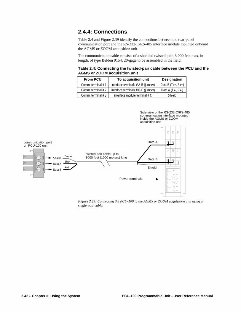
2.42 •••• Chapter II: Using the System PCU-100 Programmable Unit - User Reference Manual
2.4.4: ConnectionsTable 2.4 and Figure 2.39 identify the connections between the rear-panelcommunication port and the RS-232-C/RS-485 interface module mounted onboardthe AGMS or ZOOM acquisition unit.
The communication cable consists of a shielded twisted pair, 3 000 feet max. inlength, of type Belden 9154, 20-gage to be assembled in the field.
Table 2.4: Connecting the twisted-pair cable between the PCU and theAGMS or ZOOM acquisition unit
From PCU To acquisition unit Designation
Comm. terminal # 1 interface terminals # A-B (jumper) Data B (Tx+, Rx+)Comm. terminal # 2 interface terminals # D-E (jumper) Data A (Tx-, Rx-)Comm. terminal # 3 interface module terminal # C Shield
Data A
Data B
Shieldtwisted-pair cable up to3000 feet (1000 meters) long
Data A
Data B
Shield
communication porton PCU-100 unit
Side-view of the RS-232-C/RS-485communication interface mountedinside the AGMS or ZOOMacquisition unit
Power terminals
Red
Black
Copper
Figure 2.39: Connecting the PCU-100 to the AGMS or ZOOM acquisition unit using asingle-pair cable.
PCU-100 Programmable Unit - User Reference Manual Chapter III: The User Interface •••• 3.1
Chapter 3
The User Interface
The PCU is a software-driven programmable unit. It is designed to collect real-timesensor signals for processing into useful information and alarm event detection,management and ultimately, protection of your rotating machine investment. All thisis accomplished by the gathering and processing of the raw signals from sensorsconnected to as many as four vibration input modules. In order for the PCU unit toperform adequately in the field, it must be fitted with the appropriate hardware interms of task modules and sensors. As well, the system software must be configuredwith sensor-specific information which takes into account some design specificationsof the rotating machines. The latter is usually provided by the customer in the form ofa site survey to be forwarded to the supplier. This information will then be added tothe PCU software prior to shipment.
This chapter is provided for reference purposes only as your PCU unit comes fullyconfigured and ready for operation. Nonetheless, the next pages should prove quiteuseful in understanding unit operation as well as helping station personnel performfield upgrades to new sensors, task modules and relay cards.
Understanding of the user interface also allows users to manage the reporting ofsystem events such as alarms and OK statuses and to customize some practicalfeatures of the unit such as bar graph display IDs and conditional access codes.
Users will also be guided through the step-by-step procedures of saving aconfiguration, updating a configuration or updating the system software using thePCMCIA card slot.
Access to the various configuration and monitoring menus and sub-menus makes useof the user programmable interface by means of the VFD screen and the seven-buttonkeypad, namely:
T, U, V, S, Enter, Cancel, Menu.
This chapter will survey each menu as a step in the configuration process. Therefore,we will address each step in a chronological order. Configuration breaks down to thefollowing steps:
• General system parameters;• Vibration input modules;• Processing and analog output modules;• Digital input / output and 1/rev module;• Internal relay module;• External relay card;• Logic parameters;• Monitoring (bar graph) displays.
The next few pages will introduce some basic system characteristics and explain howthe software behaves. They will help you familiarize with the various keypad featuresas well as with the ergonomics of the user interface.
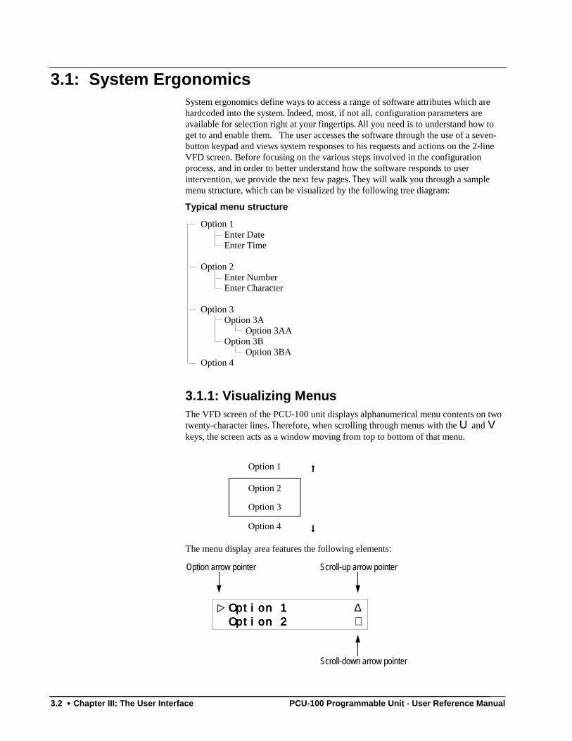
3.2 •••• Chapter III: The User Interface PCU-100 Programmable Unit - User Reference Manual
3.1: System ErgonomicsSystem ergonomics define ways to access a range of software attributes which arehardcoded into the system. Indeed, most, if not all, configuration parameters areavailable for selection right at your fingertips. All you need is to understand how toget to and enable them. The user accesses the software through the use of a seven-button keypad and views system responses to his requests and actions on the 2-lineVFD screen. Before focusing on the various steps involved in the configurationprocess, and in order to better understand how the software responds to userintervention, we provide the next few pages. They will walk you through a samplemenu structure, which can be visualized by the following tree diagram:
Typical menu structure
Option 1 Enter Date Enter Time
Option 2 Enter Number Enter Character
Option 3 Option 3A Option 3AA Option 3B Option 3BA Option 4
3.1.1: Visualizing MenusThe VFD screen of the PCU-100 unit displays alphanumerical menu contents on twotwenty-character lines. Therefore, when scrolling through menus with the U and Vkeys, the screen acts as a window moving from top to bottom of that menu.
Option 1 ↑↑↑↑
Option 2
Option 3
Option 4 ↓↓↓↓
The menu display area features the following elements:
Option 1 Option 1 Option 1 Option 1 ∆ Option 2 Option 2 Option 2 Option 2 ∇
Option arrow pointer Scroll-up arrow pointer
Scroll-down arrow pointer
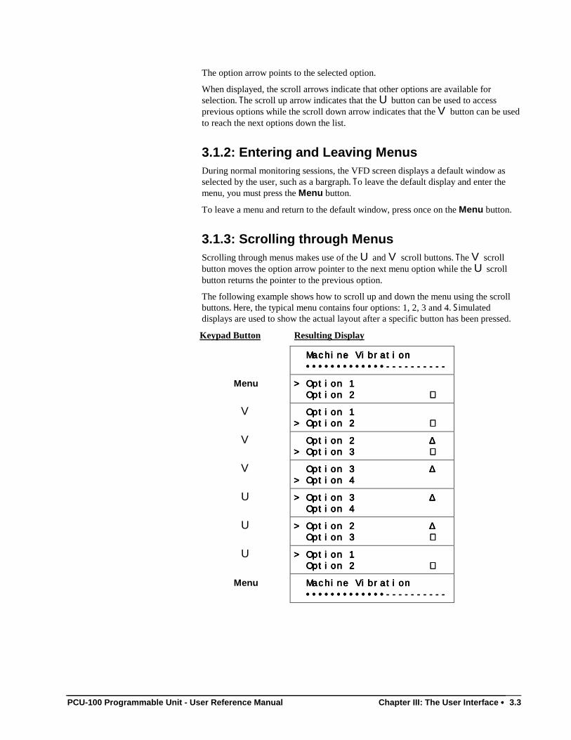
PCU-100 Programmable Unit - User Reference Manual Chapter III: The User Interface •••• 3.3
The option arrow points to the selected option.
When displayed, the scroll arrows indicate that other options are available forselection. The scroll up arrow indicates that the U button can be used to accessprevious options while the scroll down arrow indicates that the V button can be usedto reach the next options down the list.
3.1.2: Entering and Leaving MenusDuring normal monitoring sessions, the VFD screen displays a default window asselected by the user, such as a bargraph. To leave the default display and enter themenu, you must press the Menu button.
To leave a menu and return to the default window, press once on the Menu button.
3.1.3: Scrolling through MenusScrolling through menus makes use of the U and V scroll buttons. The V scrollbutton moves the option arrow pointer to the next menu option while the U scrollbutton returns the pointer to the previous option.
The following example shows how to scroll up and down the menu using the scrollbuttons. Here, the typical menu contains four options: 1, 2, 3 and 4. Simulateddisplays are used to show the actual layout after a specific button has been pressed.
Keypad Button Resulting Display
Machine Vibration Machine Vibration Machine Vibration Machine Vibration
•••••••••••••---------- •••••••••••••---------- •••••••••••••---------- •••••••••••••----------
Menu > Option 1> Option 1> Option 1> Option 1
Option 2 Option 2 Option 2 Option 2 ∇∇∇∇
V Option 1 Option 1 Option 1 Option 1
> Option 2 > Option 2 > Option 2 > Option 2 ∇∇∇∇
V Option 2 Option 2 Option 2 Option 2 ∆∆∆∆> Option 3 > Option 3 > Option 3 > Option 3 ∇∇∇∇
V Option 3 Option 3 Option 3 Option 3 ∆∆∆∆> Option 4> Option 4> Option 4> Option 4
U > Option 3 > Option 3 > Option 3 > Option 3 ∆∆∆∆ Option 4 Option 4 Option 4 Option 4
U > Option 2 > Option 2 > Option 2 > Option 2 ∆∆∆∆ Option 3 Option 3 Option 3 Option 3 ∇∇∇∇
U > Option 1> Option 1> Option 1> Option 1
Option 2 Option 2 Option 2 Option 2 ∇∇∇∇
Menu Machine Vibration Machine Vibration Machine Vibration Machine Vibration
•••••••••••••---------- •••••••••••••---------- •••••••••••••---------- •••••••••••••----------
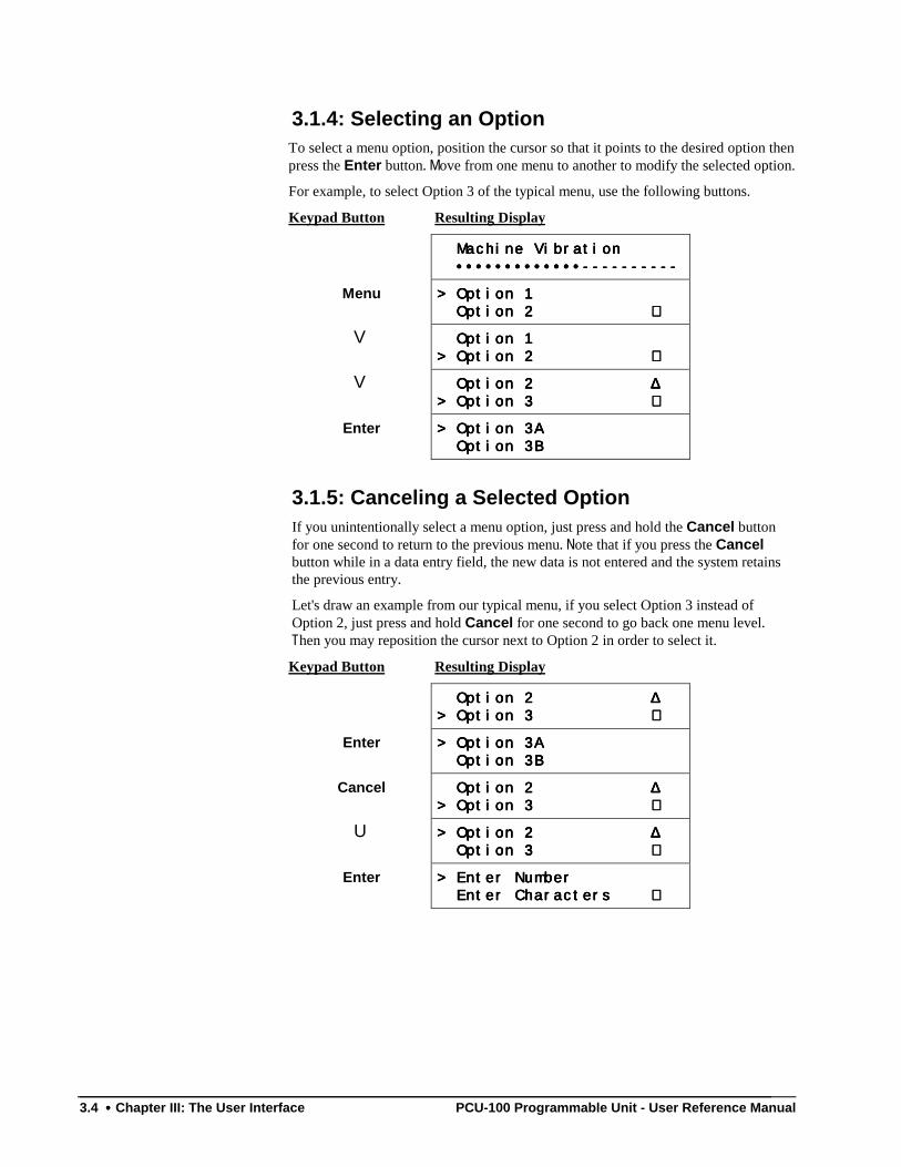
3.4 •••• Chapter III: The User Interface PCU-100 Programmable Unit - User Reference Manual
3.1.4: Selecting an OptionTo select a menu option, position the cursor so that it points to the desired option thenpress the Enter button. Move from one menu to another to modify the selected option.
For example, to select Option 3 of the typical menu, use the following buttons.
Keypad Button Resulting Display
Machine Vibration Machine Vibration Machine Vibration Machine Vibration
•••••••••••••---------- •••••••••••••---------- •••••••••••••---------- •••••••••••••----------
Menu > Option 1> Option 1> Option 1> Option 1
Option 2 Option 2 Option 2 Option 2 ∇∇∇∇
V Option 1 Option 1 Option 1 Option 1
> Option 2 > Option 2 > Option 2 > Option 2 ∇∇∇∇
V Option 2 Option 2 Option 2 Option 2 ∆∆∆∆> Option 3 > Option 3 > Option 3 > Option 3 ∇∇∇∇
Enter > Option 3A> Option 3A> Option 3A> Option 3A
Option 3B Option 3B Option 3B Option 3B
3.1.5: Canceling a Selected OptionIf you unintentionally select a menu option, just press and hold the Cancel buttonfor one second to return to the previous menu. Note that if you press the Cancelbutton while in a data entry field, the new data is not entered and the system retainsthe previous entry.
Let's draw an example from our typical menu, if you select Option 3 instead ofOption 2, just press and hold Cancel for one second to go back one menu level.Then you may reposition the cursor next to Option 2 in order to select it.
Keypad Button Resulting Display
Option 2 Option 2 Option 2 Option 2 ∆∆∆∆> Option 3 > Option 3 > Option 3 > Option 3 ∇∇∇∇
Enter > Option 3A> Option 3A> Option 3A> Option 3A
Option 3B Option 3B Option 3B Option 3B
Cancel Option 2 Option 2 Option 2 Option 2 ∆∆∆∆> Option 3 > Option 3 > Option 3 > Option 3 ∇∇∇∇
U > Option 2 > Option 2 > Option 2 > Option 2 ∆∆∆∆ Option 3 Option 3 Option 3 Option 3 ∇∇∇∇
Enter > Enter Number> Enter Number> Enter Number> Enter Number
Enter Characters Enter Characters Enter Characters Enter Characters ∇∇∇∇
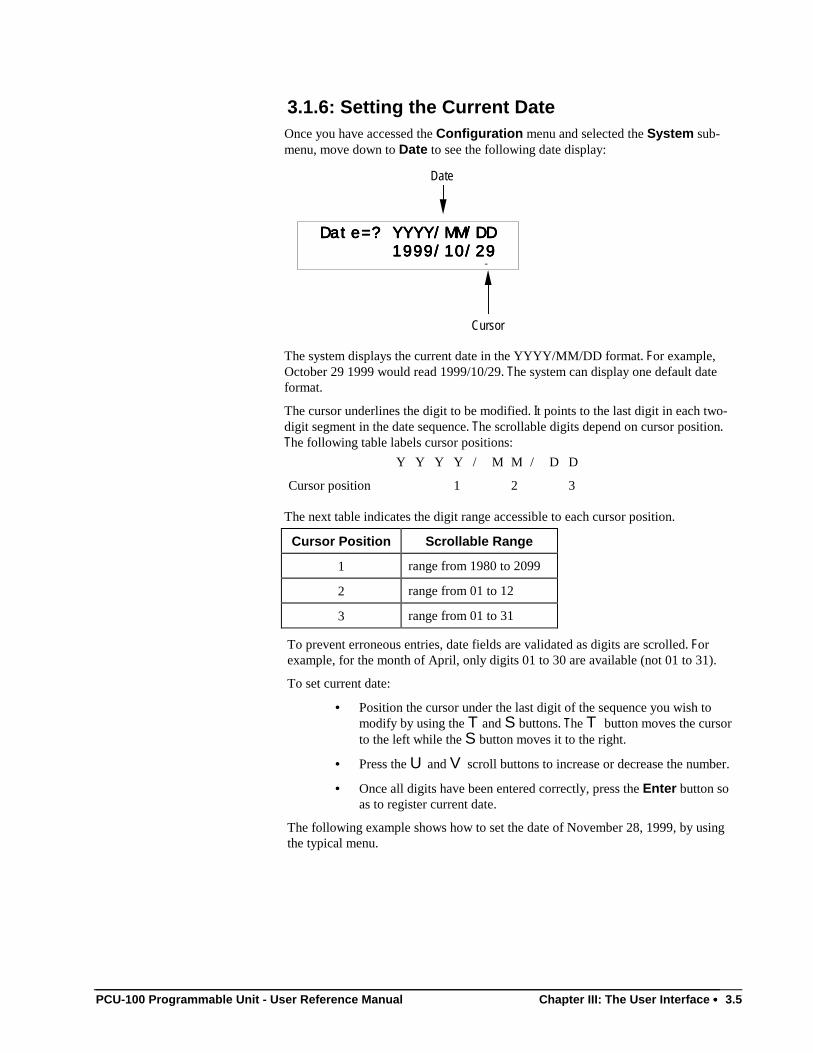
PCU-100 Programmable Unit - User Reference Manual Chapter III: The User Interface •••• 3.5
3.1.6: Setting the Current DateOnce you have accessed the Configuration menu and selected the System sub-menu, move down to Date to see the following date display:
Date=? YYYY/MM/DD Date=? YYYY/MM/DD Date=? YYYY/MM/DD Date=? YYYY/MM/DD
1999/10/29 1999/10/29 1999/10/29 1999/10/29 -
Date
Cursor
The system displays the current date in the YYYY/MM/DD format. For example,October 29 1999 would read 1999/10/29. The system can display one default dateformat.
The cursor underlines the digit to be modified. It points to the last digit in each two-digit segment in the date sequence. The scrollable digits depend on cursor position.The following table labels cursor positions:
Y Y Y Y / M M / D D
Cursor position 1 2 3
The next table indicates the digit range accessible to each cursor position.
Cursor Position Scrollable Range
1 range from 1980 to 2099
2 range from 01 to 12
3 range from 01 to 31
To prevent erroneous entries, date fields are validated as digits are scrolled. Forexample, for the month of April, only digits 01 to 30 are available (not 01 to 31).
To set current date:
• Position the cursor under the last digit of the sequence you wish tomodify by using the T and S buttons. The T button moves the cursorto the left while the S button moves it to the right.
• Press the U and V scroll buttons to increase or decrease the number.
• Once all digits have been entered correctly, press the Enter button soas to register current date.
The following example shows how to set the date of November 28, 1999, by usingthe typical menu.
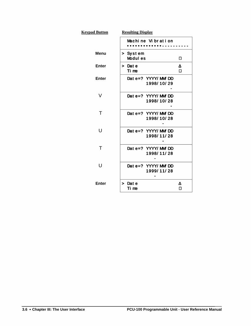
3.6 •••• Chapter III: The User Interface PCU-100 Programmable Unit - User Reference Manual
Keypad Button Resulting Display
Machine Vibration Machine Vibration Machine Vibration Machine Vibration
•••••••••••••---------- •••••••••••••---------- •••••••••••••---------- •••••••••••••----------
Menu > System> System> System> System
Modules Modules Modules Modules ∇∇∇∇
Enter > Date > Date > Date > Date ∆∆∆∆ Time Time Time Time ∇∇∇∇
Enter Date=? YYYY/MM/DD Date=? YYYY/MM/DD Date=? YYYY/MM/DD Date=? YYYY/MM/DD
1998/10/29 1998/10/29 1998/10/29 1998/10/29
- - - -
V Date=? YYYY/MM/DD Date=? YYYY/MM/DD Date=? YYYY/MM/DD Date=? YYYY/MM/DD
1998/10/28 1998/10/28 1998/10/28 1998/10/28
- - - -
T Date=? YYYY/MM/DD Date=? YYYY/MM/DD Date=? YYYY/MM/DD Date=? YYYY/MM/DD
1998/10/28 1998/10/28 1998/10/28 1998/10/28
- - - -
U Date=? YYYY/MM/DD Date=? YYYY/MM/DD Date=? YYYY/MM/DD Date=? YYYY/MM/DD
1998/11/28 1998/11/28 1998/11/28 1998/11/28
- - - -
T Date=? YYYY/MM/DD Date=? YYYY/MM/DD Date=? YYYY/MM/DD Date=? YYYY/MM/DD
1998/11/28 1998/11/28 1998/11/28 1998/11/28
- - - -
U Date=? YYYY/MM/DD Date=? YYYY/MM/DD Date=? YYYY/MM/DD Date=? YYYY/MM/DD
1999/11/28 1999/11/28 1999/11/28 1999/11/28
- - - -
Enter > Date > Date > Date > Date ∆∆∆∆ Time Time Time Time ∇∇∇∇
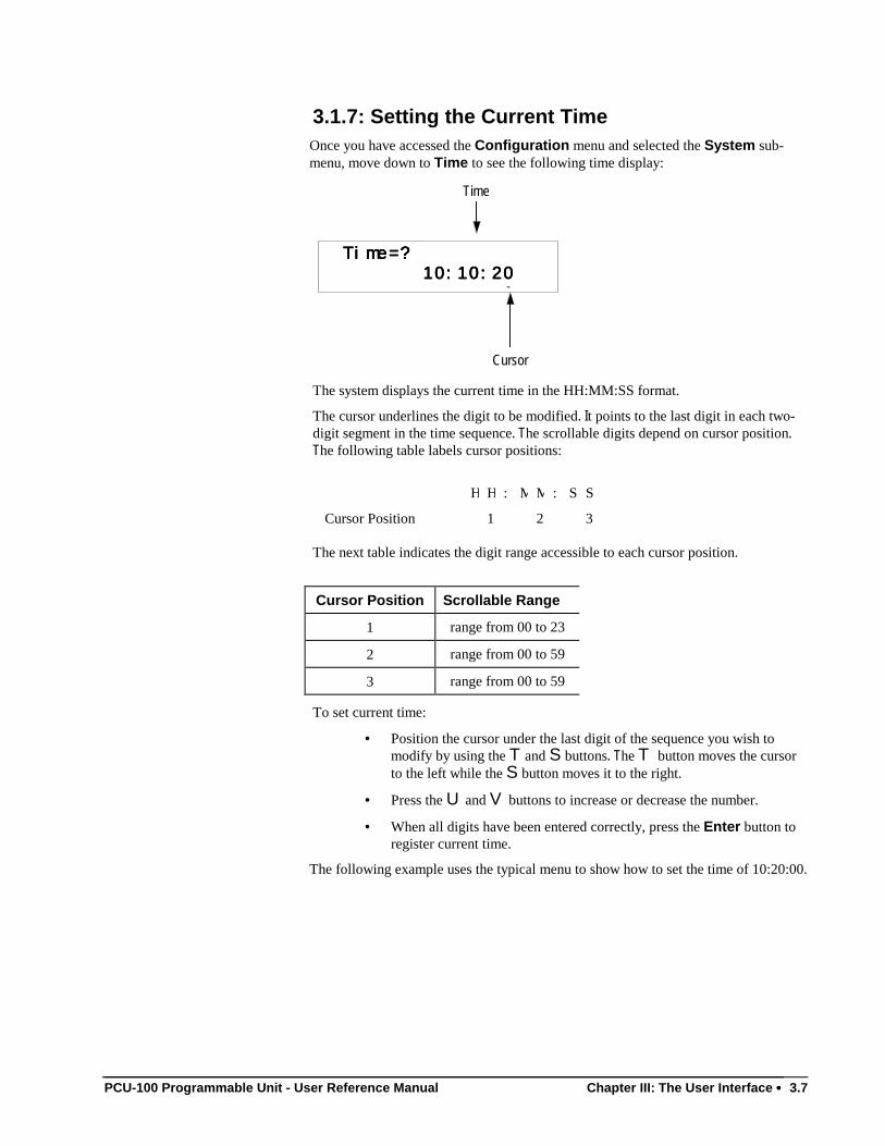
PCU-100 Programmable Unit - User Reference Manual Chapter III: The User Interface •••• 3.7
3.1.7: Setting the Current TimeOnce you have accessed the Configuration menu and selected the System sub-menu, move down to Time to see the following time display:
Time=? Time=? Time=? Time=?
10:10:20 10:10:20 10:10:20 10:10:20 -
Time
Cursor
The system displays the current time in the HH:MM:SS format.
The cursor underlines the digit to be modified. It points to the last digit in each two-digit segment in the time sequence. The scrollable digits depend on cursor position.The following table labels cursor positions:
H H : M M : S S
Cursor Position 1 2 3
The next table indicates the digit range accessible to each cursor position.
Cursor Position Scrollable Range
1 range from 00 to 23
2 range from 00 to 59
3 range from 00 to 59
To set current time:
• Position the cursor under the last digit of the sequence you wish tomodify by using the T and S buttons. The T button moves the cursorto the left while the S button moves it to the right.
• Press the U and V buttons to increase or decrease the number.
• When all digits have been entered correctly, press the Enter button toregister current time.
The following example uses the typical menu to show how to set the time of 10:20:00.
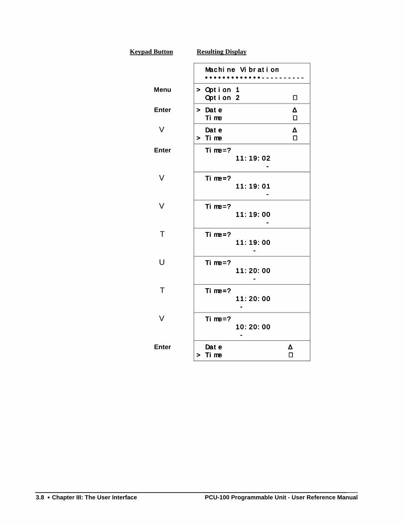
3.8 •••• Chapter III: The User Interface PCU-100 Programmable Unit - User Reference Manual
Keypad Button Resulting Display
Machine Vibration Machine Vibration Machine Vibration Machine Vibration
•••••••••••••---------- •••••••••••••---------- •••••••••••••---------- •••••••••••••----------
Menu > Option 1> Option 1> Option 1> Option 1
Option 2 Option 2 Option 2 Option 2 ∇∇∇∇
Enter > Date > Date > Date > Date ∆∆∆∆ Time Time Time Time ∇∇∇∇
V Date Date Date Date ∆∆∆∆> Time > Time > Time > Time ∇∇∇∇
Enter Time=? Time=? Time=? Time=?
11:19:02 11:19:02 11:19:02 11:19:02
- - - -
V Time=? Time=? Time=? Time=?
11:19:01 11:19:01 11:19:01 11:19:01
- - - -
V Time=? Time=? Time=? Time=?
11:19:00 11:19:00 11:19:00 11:19:00
- - - -
T Time=? Time=? Time=? Time=?
11:19:00 11:19:00 11:19:00 11:19:00
- - - -
U Time=? Time=? Time=? Time=?
11:20:00 11:20:00 11:20:00 11:20:00
- - - -
T Time=? Time=? Time=? Time=?
11:20:00 11:20:00 11:20:00 11:20:00
- - - -
V Time=? Time=? Time=? Time=?
10:20:00 10:20:00 10:20:00 10:20:00
- - - -
Enter Date Date Date Date ∆∆∆∆> Time > Time > Time > Time ∇∇∇∇
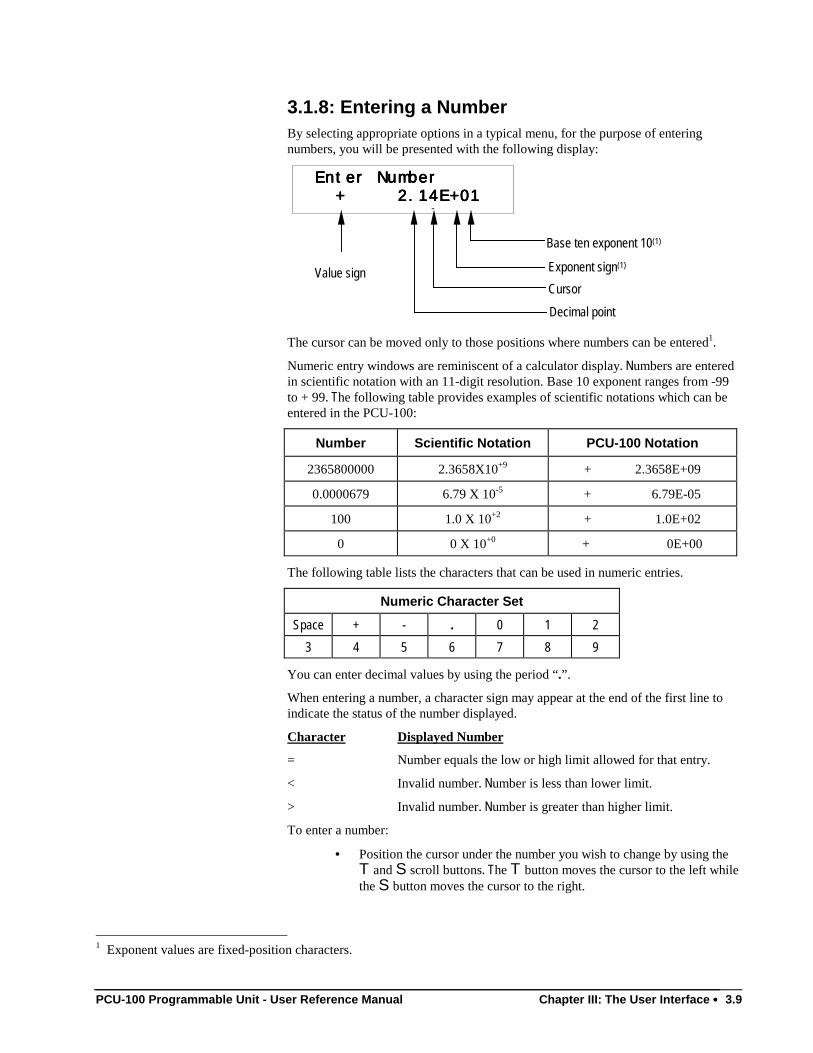
PCU-100 Programmable Unit - User Reference Manual Chapter III: The User Interface •••• 3.9
3.1.8: Entering a NumberBy selecting appropriate options in a typical menu, for the purpose of enteringnumbers, you will be presented with the following display:
Enter Number Enter Number Enter Number Enter Number
+ 2.14E+01 + 2.14E+01 + 2.14E+01 + 2.14E+01 -
Value sign
Base ten exponent 10(1)
Exponent sign(1)
Cursor
Decimal point
The cursor can be moved only to those positions where numbers can be entered1.
Numeric entry windows are reminiscent of a calculator display. Numbers are enteredin scientific notation with an 11-digit resolution. Base 10 exponent ranges from -99to + 99. The following table provides examples of scientific notations which can beentered in the PCU-100:
Number Scientific Notation PCU-100 Notation
2365800000 2.3658X10+9 + 2.3658E+09
0.0000679 6.79 X 10⁻⁵ + 6.79E-05
100 1.0 X 10+2 + 1.0E+02
0 0 X 10+0 + 0E+00
The following table lists the characters that can be used in numeric entries.
Numeric Character Set
Space + - . 0 1 2
3 4 5 6 7 8 9
You can enter decimal values by using the period “.”.
When entering a number, a character sign may appear at the end of the first line toindicate the status of the number displayed.
Character Displayed Number
= Number equals the low or high limit allowed for that entry.
< Invalid number. Number is less than lower limit.
> Invalid number. Number is greater than higher limit.
To enter a number:
• Position the cursor under the number you wish to change by using theT and S scroll buttons. The T button moves the cursor to the left whilethe S button moves the cursor to the right.
1 Exponent values are fixed-position characters.
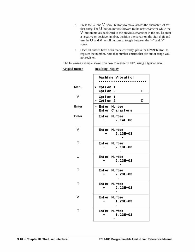
3.10 •••• Chapter III: The User Interface PCU-100 Programmable Unit - User Reference Manual
• Press the U and V scroll buttons to move across the character set forthat entry. The U button moves forward to the next character while theV button moves backward to the previous character in the set. To entera negative or positive number, position the cursor on the sign digit anduse the U and V scroll buttons to toggle between the “+” and “-”signs.
• Once all entries have been made correctly, press the Enter button toregister the number. Note that number entries that are out of range willnot register.
The following example shows you how to register 0.0123 using a typical menu.
Keypad Button Resulting Display
Machine Vibration Machine Vibration Machine Vibration Machine Vibration
•••••••••••••---------- •••••••••••••---------- •••••••••••••---------- •••••••••••••----------
Menu > Option 1> Option 1> Option 1> Option 1
Option 2 Option 2 Option 2 Option 2 ∇∇∇∇
V Option 1 Option 1 Option 1 Option 1
> Option 2 > Option 2 > Option 2 > Option 2 ∇∇∇∇
Enter > Enter Number> Enter Number> Enter Number> Enter Number
Enter Characters Enter Characters Enter Characters Enter Characters
Enter Enter Number Enter Number Enter Number Enter Number
+ 2.14E+03 + 2.14E+03 + 2.14E+03 + 2.14E+03
- - - -
V Enter Number Enter Number Enter Number Enter Number
+ 2.13E+03 + 2.13E+03 + 2.13E+03 + 2.13E+03
- - - -
T Enter Number Enter Number Enter Number Enter Number
+ 2.13E+03 + 2.13E+03 + 2.13E+03 + 2.13E+03
- - - -
U Enter Number Enter Number Enter Number Enter Number
+ 2.23E+03 + 2.23E+03 + 2.23E+03 + 2.23E+03
- - - -
T Enter Number Enter Number Enter Number Enter Number
+ 2.23E+03 + 2.23E+03 + 2.23E+03 + 2.23E+03
- - - -
T Enter Number Enter Number Enter Number Enter Number
+ 2.23E+03 + 2.23E+03 + 2.23E+03 + 2.23E+03
- - - -
V Enter Number Enter Number Enter Number Enter Number
+ 1.23E+03 + 1.23E+03 + 1.23E+03 + 1.23E+03
- - - -
T Enter Number Enter Number Enter Number Enter Number
+ 1.23E+03 + 1.23E+03 + 1.23E+03 + 1.23E+03
- - - -
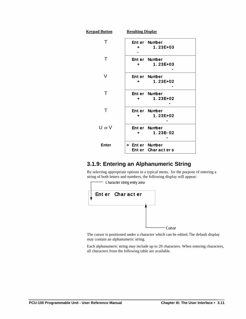
PCU-100 Programmable Unit - User Reference Manual Chapter III: The User Interface •••• 3.11
Keypad Button Resulting Display
T Enter Number Enter Number Enter Number Enter Number
+ 1.23E+03 + 1.23E+03 + 1.23E+03 + 1.23E+03
- - - -
T Enter Number Enter Number Enter Number Enter Number
+ 1.23E+03 + 1.23E+03 + 1.23E+03 + 1.23E+03
- - - -
V Enter Number Enter Number Enter Number Enter Number
+ 1.23E+02 + 1.23E+02 + 1.23E+02 + 1.23E+02
- - - -
T Enter Number Enter Number Enter Number Enter Number
+ 1.23E+02 + 1.23E+02 + 1.23E+02 + 1.23E+02
- - - -
T Enter Number Enter Number Enter Number Enter Number
+ 1.23E+02 + 1.23E+02 + 1.23E+02 + 1.23E+02
- - - -
U or V Enter Number Enter Number Enter Number Enter Number
+ 1.23E-02 + 1.23E-02 + 1.23E-02 + 1.23E-02
- - - -
Enter > Enter Number> Enter Number> Enter Number> Enter Number
Enter Characters Enter Characters Enter Characters Enter Characters
3.1.9: Entering an Alphanumeric StringBy selecting appropriate options in a typical menu, for the purpose of entering astring of both letters and numbers, the following display will appear:
Enter Character Enter Character Enter Character Enter Character
-
Character string entry area
Cursor
The cursor is positioned under a character which can be edited. The default displaymay contain an alphanumeric string.
Each alphanumeric string may include up to 20 characters. When entering characters,all characters from the following table are available.
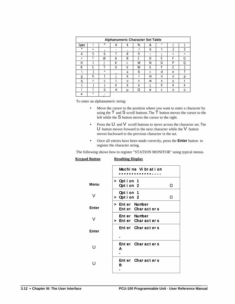
3.12 •••• Chapter III: The User Interface PCU-100 Programmable Unit - User Reference Manual
Alphanumeric Character Set Table
Space ! “ # $ % & ‘ ( )* + , - . / 0 1 2 34 5 6 7 8 9 : ; < => ? @ A B C D E F GH I J K L M N O P QR S T U V W X Y Z [\ ] ^ _ a b c d e fg h I j k l m n o pq r s t u v w x y z | é â à ç ê ë èï î û π µ Ω ø ± ≥ ≤÷÷÷÷ °
To enter an alphanumeric string:
• Move the cursor to the position where you want to enter a character byusing the T and S scroll buttons. The T button moves the cursor to theleft while the S button moves the cursor to the right.
• Press the U and V scroll buttons to move across the character set. TheU button moves forward to the next character while the V buttonmoves backward to the previous character in the set.
• Once all entries have been made correctly, press the Enter button toregister the character string.
The following shows how to register "STATION MONITOR" using typical menus.
Keypad Button Resulting Display
Machine Vibration Machine Vibration Machine Vibration Machine Vibration
•••••••••••••---- •••••••••••••---- •••••••••••••---- •••••••••••••----
Menu> Option 1> Option 1> Option 1> Option 1
Option 2 Option 2 Option 2 Option 2 ∇∇∇∇
V Option 1 Option 1 Option 1 Option 1
> Option 2 > Option 2 > Option 2 > Option 2 ∇∇∇∇
Enter> Enter Number> Enter Number> Enter Number> Enter Number
Enter Characters Enter Characters Enter Characters Enter Characters
V Enter Number Enter Number Enter Number Enter Number
> Enter Characters> Enter Characters> Enter Characters> Enter Characters
Enter Enter Characters Enter Characters Enter Characters Enter Characters
- - - -
U Enter Characters Enter Characters Enter Characters Enter Characters
A A A A
- - - -
U Enter Characters Enter Characters Enter Characters Enter Characters
B B B B
- - - -
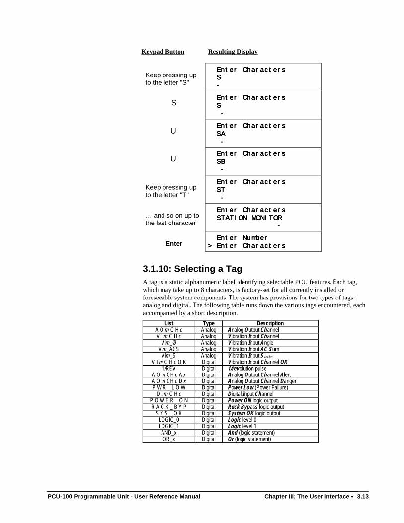
PCU-100 Programmable Unit - User Reference Manual Chapter III: The User Interface •••• 3.13
Keypad Button Resulting Display
Keep pressing upto the letter "S"
Enter Characters Enter Characters Enter Characters Enter Characters
S S S S
- - - -
S Enter Characters Enter Characters Enter Characters Enter Characters
S S S S
- - - -
U Enter Characters Enter Characters Enter Characters Enter Characters
SA SA SA SA
- - - -
U Enter Characters Enter Characters Enter Characters Enter Characters
SB SB SB SB
- - - -
Keep pressing upto the letter "T"
Enter Characters Enter Characters Enter Characters Enter Characters
ST ST ST ST
- - - -
… and so on up tothe last character
Enter Characters Enter Characters Enter Characters Enter Characters
STATION MONITOR STATION MONITOR STATION MONITOR STATION MONITOR
- - - -
Enter Enter Number Enter Number Enter Number Enter Number
> Enter Characters> Enter Characters> Enter Characters> Enter Characters
3.1.10: Selecting a TagA tag is a static alphanumeric label identifying selectable PCU features. Each tag,which may take up to 8 characters, is factory-set for all currently installed orforeseeable system components. The system has provisions for two types of tags:analog and digital. The following table runs down the various tags encountered, eachaccompanied by a short description.
List Type DescriptionA O m C H c Analog Analog Output ChannelV I m C H c Analog Vibration Input Channel
Vim_Ø Analog Vibration Input AngleVim_ACS Analog Vibration Input AC Sum
Vim_S Analog Vibration Input SvectorV I m C H c O K Digital Vibration Input Channel OK
1/REV Digital 1/revolution pulseA O m CH c A x Digital Analog Output Channel AlertA O m CH c D x Digital Analog Output Channel DangerP W R _ L O W Digital Power Low (Power Failure)
D I m C H c Digital Digital Input ChannelP O W E R _ O N Digital Power ON logic outputR A C K _ B Y P Digital Rack Bypass logic output
S Y S _ O K Digital System OK logic outputLOGIC_0 Digital Logic level 0LOGIC_1 Digital Logic level 1AND_x Digital And (logic statement)OR_x Digital Or (logic statement)
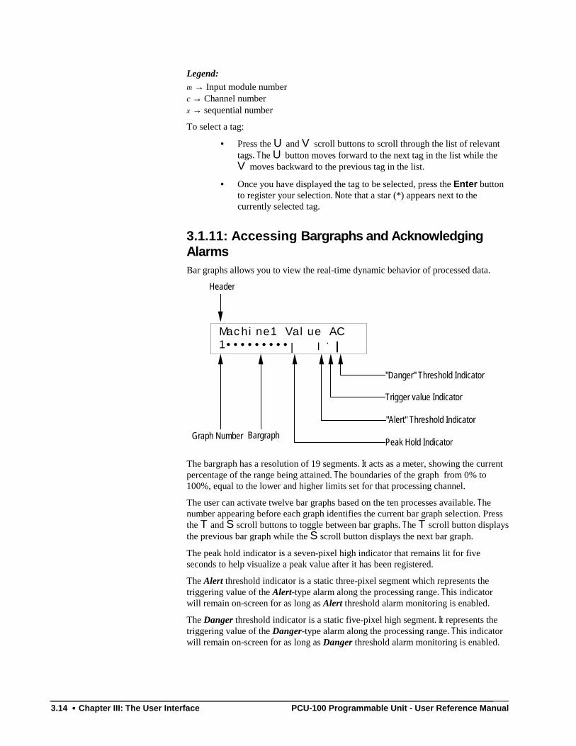
3.14 •••• Chapter III: The User Interface PCU-100 Programmable Unit - User Reference Manual
Legend:m → Input module numberc → Channel numberx → sequential number
To select a tag:
• Press the U and V scroll buttons to scroll through the list of relevanttags. The U button moves forward to the next tag in the list while theV moves backward to the previous tag in the list.
• Once you have displayed the tag to be selected, press the Enter buttonto register your selection. Note that a star (*) appears next to thecurrently selected tag.
3.1.11: Accessing Bargraphs and AcknowledgingAlarmsBar graphs allows you to view the real-time dynamic behavior of processed data.
Machine1 Value AC
1•••••••••| |||| .... ||||
Graph Number BargraphPeak Hold Indicator
"Alert" Threshold Indicator
Trigger value Indicator
"Danger" Threshold Indicator
Header
The bargraph has a resolution of 19 segments. It acts as a meter, showing the currentpercentage of the range being attained. The boundaries of the graph from 0% to100%, equal to the lower and higher limits set for that processing channel.
The user can activate twelve bar graphs based on the ten processes available. Thenumber appearing before each graph identifies the current bar graph selection. Pressthe T and S scroll buttons to toggle between bar graphs. The T scroll button displaysthe previous bar graph while the S scroll button displays the next bar graph.
The peak hold indicator is a seven-pixel high indicator that remains lit for fiveseconds to help visualize a peak value after it has been registered.
The Alert threshold indicator is a static three-pixel segment which represents thetriggering value of the Alert-type alarm along the processing range. This indicatorwill remain on-screen for as long as Alert threshold alarm monitoring is enabled.
The Danger threshold indicator is a static five-pixel high segment. It represents thetriggering value of the Danger-type alarm along the processing range. This indicatorwill remain on-screen for as long as Danger threshold alarm monitoring is enabled.
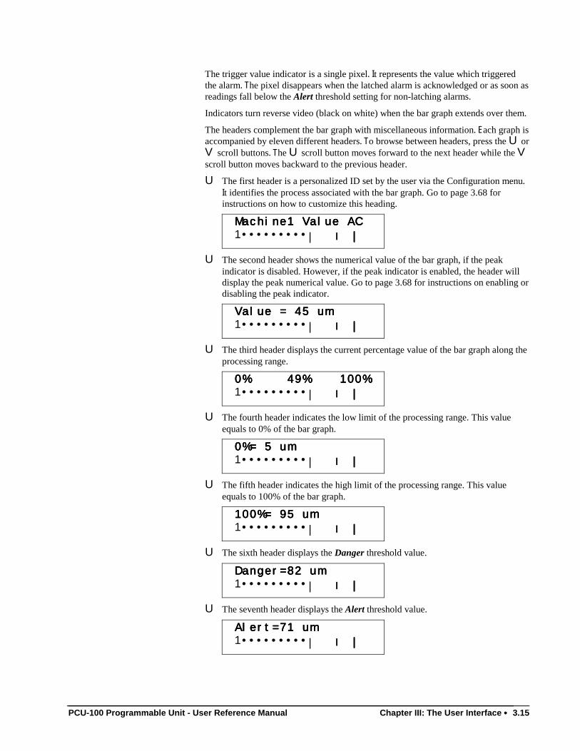
PCU-100 Programmable Unit - User Reference Manual Chapter III: The User Interface •••• 3.15
The trigger value indicator is a single pixel. It represents the value which triggeredthe alarm. The pixel disappears when the latched alarm is acknowledged or as soon asreadings fall below the Alert threshold setting for non-latching alarms.
Indicators turn reverse video (black on white) when the bar graph extends over them.
The headers complement the bar graph with miscellaneous information. Each graph isaccompanied by eleven different headers. To browse between headers, press the U orV scroll buttons. The U scroll button moves forward to the next header while the Vscroll button moves backward to the previous header.
U The first header is a personalized ID set by the user via the Configuration menu.It identifies the process associated with the bar graph. Go to page 3.68 forinstructions on how to customize this heading.
Machine1 Value ACMachine1 Value ACMachine1 Value ACMachine1 Value AC
1•••••••••| |||| ||||
U The second header shows the numerical value of the bar graph, if the peakindicator is disabled. However, if the peak indicator is enabled, the header willdisplay the peak numerical value. Go to page 3.68 for instructions on enabling ordisabling the peak indicator.
Value = 45 umValue = 45 umValue = 45 umValue = 45 um
1•••••••••| |||| ||||
U The third header displays the current percentage value of the bar graph along theprocessing range.
0% 49% 100%0% 49% 100%0% 49% 100%0% 49% 100%
1•••••••••| |||| ||||
U The fourth header indicates the low limit of the processing range. This valueequals to 0% of the bar graph.
0%= 5 um0%= 5 um0%= 5 um0%= 5 um
1•••••••••| |||| ||||
U The fifth header indicates the high limit of the processing range. This valueequals to 100% of the bar graph.
100%= 95 um100%= 95 um100%= 95 um100%= 95 um
1•••••••••| |||| ||||
U The sixth header displays the Danger threshold value.
Danger=82 umDanger=82 umDanger=82 umDanger=82 um
1•••••••••| |||| ||||
U The seventh header displays the Alert threshold value.
Alert=71 umAlert=71 umAlert=71 umAlert=71 um
1•••••••••| |||| ||||
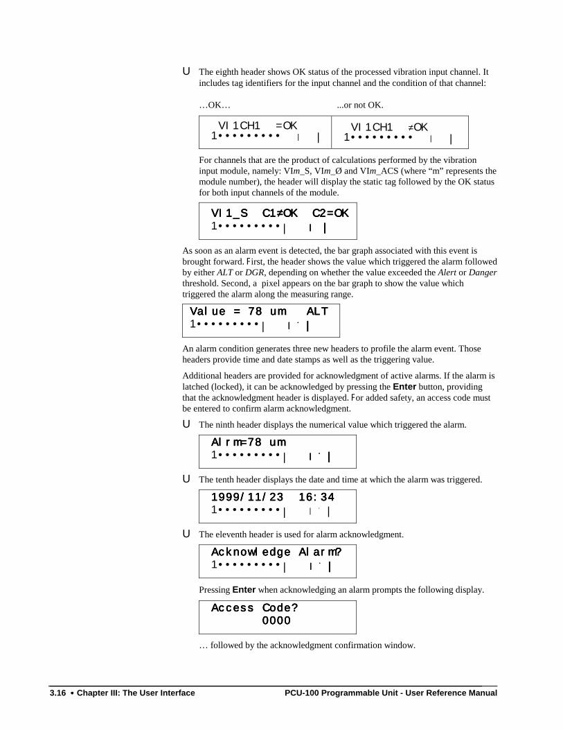
3.16 •••• Chapter III: The User Interface PCU-100 Programmable Unit - User Reference Manual
U The eighth header shows OK status of the processed vibration input channel. Itincludes tag identifiers for the input channel and the condition of that channel:
…OK… ...or not OK.
VI1CH1 =OK 1••••••••• | |
VI1CH1 ≠OK 1••••••••• | |
For channels that are the product of calculations performed by the vibrationinput module, namely: VIm_S, VIm_Ø and VIm_ACS (where “m” represents themodule number), the header will display the static tag followed by the OK statusfor both input channels of the module.
VI1_S C1VI1_S C1VI1_S C1VI1_S C1≠≠≠≠OK C2=OKOK C2=OKOK C2=OKOK C2=OK
1•••••••••| |||| ||||
As soon as an alarm event is detected, the bar graph associated with this event isbrought forward. First, the header shows the value which triggered the alarm followedby either ALT or DGR, depending on whether the value exceeded the Alert or Dangerthreshold. Second, a pixel appears on the bar graph to show the value whichtriggered the alarm along the measuring range.
Value = 78 um ALTValue = 78 um ALTValue = 78 um ALTValue = 78 um ALT
1•••••••••| |||| .... ||||
An alarm condition generates three new headers to profile the alarm event. Thoseheaders provide time and date stamps as well as the triggering value.
Additional headers are provided for acknowledgment of active alarms. If the alarm islatched (locked), it can be acknowledged by pressing the Enter button, providingthat the acknowledgment header is displayed. For added safety, an access code mustbe entered to confirm alarm acknowledgment.
U The ninth header displays the numerical value which triggered the alarm.
Alrm=78 umAlrm=78 umAlrm=78 umAlrm=78 um
1•••••••••| |||| .... ||||
U The tenth header displays the date and time at which the alarm was triggered.
1999/11/23 16:341999/11/23 16:341999/11/23 16:341999/11/23 16:34
1•••••••••| | . |
U The eleventh header is used for alarm acknowledgment.
Acknowledge Alarm?Acknowledge Alarm?Acknowledge Alarm?Acknowledge Alarm?
1•••••••••| |||| .... ||||
Pressing Enter when acknowledging an alarm prompts the following display.
Access Code?Access Code?Access Code?Access Code?
0000 0000 0000 0000
… followed by the acknowledgment confirmation window.
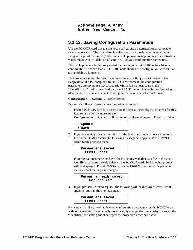
PCU-100 Programmable Unit - User Reference Manual Chapter III: The User Interface •••• 3.17
Acknowledge Alarm?Acknowledge Alarm?Acknowledge Alarm?Acknowledge Alarm?
Enter=Yes Cancel=No Enter=Yes Cancel=No Enter=Yes Cancel=No Enter=Yes Cancel=No
3.1.12: Saving Configuration ParametersUse the PCMCIA card slot to save your configuration parameters on a removableflash memory card. The procedure described next is strongly recommended as asafeguard against the unlikely event of a backup power outage, or any other situationwhich might lead to a deletion of some or all of your configuration parameters.
This backup feature is also very useful for cloning other PCU-100 units with oneconfiguration provided that all PCU-100 units sharing the configuration have similartask module assignments.
This procedure resembles that of saving a file onto a floppy disk inserted in thefloppy drive of a PC computer. In the PCU environment, the configurationparameters are saved in a .CFG-type file whose full name appears in the“Identification” setting described on page 3.25. To set or change the configurationidentification filename, access the configuration menu and select as follows:
Configuration →→→→ System →→→→ Identification.
Proceed as follows to save the configuration parameters:
1. Insert a PCMCIA card into a card slot and access the configuration menu for thisfeature in the following sequence:Configuration →→→→ System →→→→ Parameters →→→→ Save, then press Enter to initiate.
Update Update Update Update
> > > > SaveSaveSaveSave
2. If you are saving this configuration for the first time, that is, you are creating afile on the PCMCIA card, the following message will appear. Press Enter toreturn to the previous menu.
Parameters saved Parameters saved Parameters saved Parameters saved
Press Enter Press Enter Press Enter Press Enter
If configuration parameters have already been saved, that is, a file of the sameidentification name already exists on the PCMCIA card, the following promptwill be displayed. Press Enter to replace or Cancel to return to the previousmenu without making any changes.
Param. already saved Param. already saved Param. already saved Param. already saved
Replace it? Replace it? Replace it? Replace it?
3. If you pressed Enter to replace, the following will be displayed. Press Enteragain to return to the previous menu.
Parameters saved Parameters saved Parameters saved Parameters saved
Press Enter Press Enter Press Enter Press Enter
Remember that if you wish to backup configuration parameters on the PCMCIA cardwithout overwriting those already saved, simply change the filename by accessing the“Identification” setting and then repeat the procedure described above.
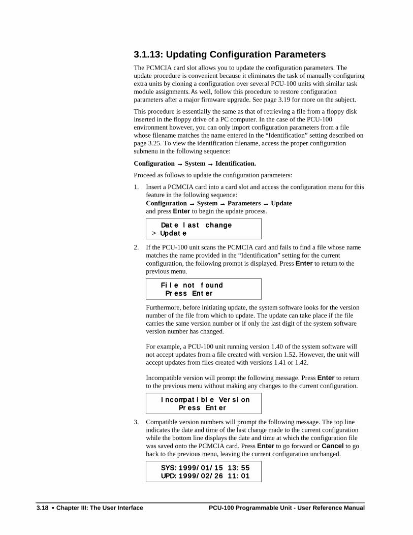
3.18 •••• Chapter III: The User Interface PCU-100 Programmable Unit - User Reference Manual
3.1.13: Updating Configuration ParametersThe PCMCIA card slot allows you to update the configuration parameters. Theupdate procedure is convenient because it eliminates the task of manually configuringextra units by cloning a configuration over several PCU-100 units with similar taskmodule assignments. As well, follow this procedure to restore configurationparameters after a major firmware upgrade. See page 3.19 for more on the subject.
This procedure is essentially the same as that of retrieving a file from a floppy diskinserted in the floppy drive of a PC computer. In the case of the PCU-100environment however, you can only import configuration parameters from a filewhose filename matches the name entered in the “Identification” setting described onpage 3.25. To view the identification filename, access the proper configurationsubmenu in the following sequence:
Configuration →→→→ System →→→→ Identification.
Proceed as follows to update the configuration parameters:
1. Insert a PCMCIA card into a card slot and access the configuration menu for thisfeature in the following sequence:Configuration →→→→ System →→→→ Parameters →→→→ Updateand press Enter to begin the update process.
Date last change Date last change Date last change Date last change
> Update Update Update Update
2. If the PCU-100 unit scans the PCMCIA card and fails to find a file whose namematches the name provided in the “Identification” setting for the currentconfiguration, the following prompt is displayed. Press Enter to return to theprevious menu.
File not found File not found File not found File not found
Press Enter Press Enter Press Enter Press Enter
Furthermore, before initiating update, the system software looks for the versionnumber of the file from which to update. The update can take place if the filecarries the same version number or if only the last digit of the system softwareversion number has changed.
For example, a PCU-100 unit running version 1.40 of the system software willnot accept updates from a file created with version 1.52. However, the unit willaccept updates from files created with versions 1.41 or 1.42.
Incompatible version will prompt the following message. Press Enter to returnto the previous menu without making any changes to the current configuration.
Incompatible Version Incompatible Version Incompatible Version Incompatible Version
Press Enter Press Enter Press Enter Press Enter
3. Compatible version numbers will prompt the following message. The top lineindicates the date and time of the last change made to the current configurationwhile the bottom line displays the date and time at which the configuration filewas saved onto the PCMCIA card. Press Enter to go forward or Cancel to goback to the previous menu, leaving the current configuration unchanged.
SYS:1999/01/15 13:55 SYS:1999/01/15 13:55 SYS:1999/01/15 13:55 SYS:1999/01/15 13:55
UPD:1999/02/26 11:01 UPD:1999/02/26 11:01 UPD:1999/02/26 11:01 UPD:1999/02/26 11:01
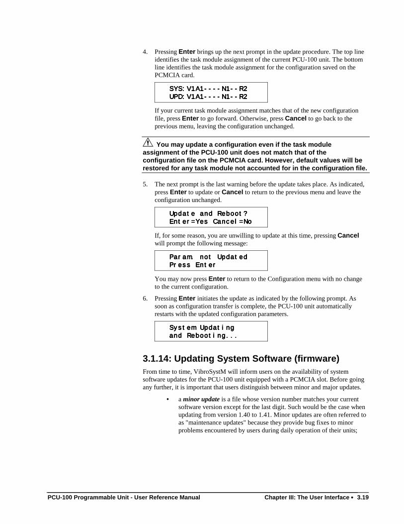
PCU-100 Programmable Unit - User Reference Manual Chapter III: The User Interface •••• 3.19
4. Pressing Enter brings up the next prompt in the update procedure. The top lineidentifies the task module assignment of the current PCU-100 unit. The bottomline identifies the task module assignment for the configuration saved on thePCMCIA card.
SYS:V1A1----N1--R2 SYS:V1A1----N1--R2 SYS:V1A1----N1--R2 SYS:V1A1----N1--R2
UPD:V1A1----N1--R2 UPD:V1A1----N1--R2 UPD:V1A1----N1--R2 UPD:V1A1----N1--R2
If your current task module assignment matches that of the new configurationfile, press Enter to go forward. Otherwise, press Cancel to go back to theprevious menu, leaving the configuration unchanged.
You may update a configuration even if the task moduleassignment of the PCU-100 unit does not match that of theconfiguration file on the PCMCIA card. However, default values will berestored for any task module not accounted for in the configuration file.
5. The next prompt is the last warning before the update takes place. As indicated,press Enter to update or Cancel to return to the previous menu and leave theconfiguration unchanged.
Update and Reboot? Update and Reboot? Update and Reboot? Update and Reboot?
Enter=Yes Cancel=No Enter=Yes Cancel=No Enter=Yes Cancel=No Enter=Yes Cancel=No
If, for some reason, you are unwilling to update at this time, pressing Cancelwill prompt the following message:
Param. not Updated Param. not Updated Param. not Updated Param. not Updated
Press Enter Press Enter Press Enter Press Enter
You may now press Enter to return to the Configuration menu with no changeto the current configuration.
6. Pressing Enter initiates the update as indicated by the following prompt. Assoon as configuration transfer is complete, the PCU-100 unit automaticallyrestarts with the updated configuration parameters.
System Updating System Updating System Updating System Updating
and Rebooting... and Rebooting... and Rebooting... and Rebooting...
3.1.14: Updating System Software (firmware)From time to time, VibroSystM will inform users on the availability of systemsoftware updates for the PCU-100 unit equipped with a PCMCIA slot. Before goingany further, it is important that users distinguish between minor and major updates.
• a minor update is a file whose version number matches your currentsoftware version except for the last digit. Such would be the case whenupdating from version 1.40 to 1.41. Minor updates are often referred toas "maintenance updates" because they provide bug fixes to minorproblems encountered by users during daily operation of their units;
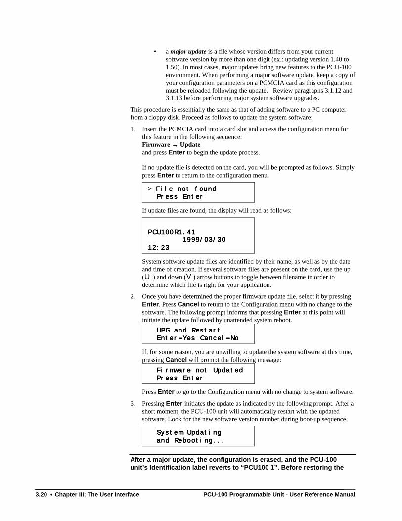
3.20 •••• Chapter III: The User Interface PCU-100 Programmable Unit - User Reference Manual
• a major update is a file whose version differs from your currentsoftware version by more than one digit (ex.: updating version 1.40 to1.50). In most cases, major updates bring new features to the PCU-100environment. When performing a major software update, keep a copy ofyour configuration parameters on a PCMCIA card as this configurationmust be reloaded following the update. Review paragraphs 3.1.12 and3.1.13 before performing major system software upgrades.
This procedure is essentially the same as that of adding software to a PC computerfrom a floppy disk. Proceed as follows to update the system software:
1. Insert the PCMCIA card into a card slot and access the configuration menu forthis feature in the following sequence:Firmware →→→→ Updateand press Enter to begin the update process.
If no update file is detected on the card, you will be prompted as follows. Simplypress Enter to return to the configuration menu.
> File not found File not found File not found File not found
Press Enter Press Enter Press Enter Press Enter
If update files are found, the display will read as follows:
PCU100R1.41PCU100R1.41PCU100R1.41PCU100R1.41
1999/03/30 1999/03/30 1999/03/30 1999/03/30
12:2312:2312:2312:23
System software update files are identified by their name, as well as by the dateand time of creation. If several software files are present on the card, use the up(U ) and down (V) arrow buttons to toggle between filename in order todetermine which file is right for your application.
2. Once you have determined the proper firmware update file, select it by pressingEnter. Press Cancel to return to the Configuration menu with no change to thesoftware. The following prompt informs that pressing Enter at this point willinitiate the update followed by unattended system reboot.
UPG and Restart UPG and Restart UPG and Restart UPG and Restart
Enter=Yes Cancel=No Enter=Yes Cancel=No Enter=Yes Cancel=No Enter=Yes Cancel=No
If, for some reason, you are unwilling to update the system software at this time,pressing Cancel will prompt the following message:
Firmware not Updated Firmware not Updated Firmware not Updated Firmware not Updated
Press Enter Press Enter Press Enter Press Enter
Press Enter to go to the Configuration menu with no change to system software.
3. Pressing Enter initiates the update as indicated by the following prompt. After ashort moment, the PCU-100 unit will automatically restart with the updatedsoftware. Look for the new software version number during boot-up sequence.
System Updating System Updating System Updating System Updating
and Rebooting... and Rebooting... and Rebooting... and Rebooting...
After a major update, the configuration is erased, and the PCU-100unit’s Identification label reverts to “PCU100 1”. Before restoring the
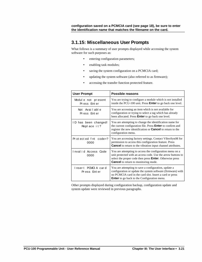
PCU-100 Programmable Unit - User Reference Manual Chapter III: The User Interface •••• 3.21
configuration saved on a PCMCIA card (see page 18), be sure to enterthe identification name that matches the filename on the card.
3.1.15: Miscellaneous User PromptsWhat follows is a summary of user prompts displayed while accessing the systemsoftware for such purposes as:
• entering configuration parameters;
• enabling task modules;
• saving the system configuration on a PCMCIA card;
• updating the system software (also referred to as firmware);
• accessing the transfer function protected feature.
User Prompt Possible reasons
Module not present Press Enter
You are trying to configure a module which is not installedinside the PCU-100 unit. Press Enter to go back one level.
Not Available Press Enter
You are accessing an item which is not available forconfiguration or trying to select a tag which has alreadybeen allocated. Press Enter to go back one level.
ID has been changed! Replace it?
You are attempting to change the identification name forthe current configuration file. Press Enter to confirm andregister the new identification or Cancel to return to theconfiguration menu.
Protected fnt code=? 0000
You are accessing factory settings. Contact VibroSystM forpermission to access this configuration feature. PressCancel to return to the vibration input channel attributes.
Invalid Access Code 0000
You are attempting to access the configuration menu on aunit protected with an access code. Use the arrow buttons toselect the proper code then press Enter. Otherwise pressCancel to return to monitoring mode.
Insert PCMCIA card Press Enter
You are attempting to save a configuration, update aconfiguration or update the system software (firmware) withno PCMCIA card in the card slot. Insert a card or pressEnter to go back to the Configuration menu.
Other prompts displayed during configuration backup, configuration update andsystem update were reviewed in previous paragraphs.
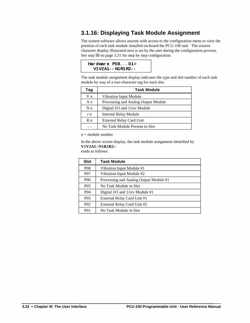
3.22 •••• Chapter III: The User Interface PCU-100 Programmable Unit - User Reference Manual
3.1.16: Displaying Task Module AssignmentThe system software allows anyone with access to the configuration menu to view theposition of each task module installed on-board the PCU-100 unit The sixteencharacter display illustrated next is set by the user during the configuration process.See step 50 on page 3.31 for step by step configuration.
Hardware P08...01= Hardware P08...01= Hardware P08...01= Hardware P08...01=
V1V2A1--N1R1R2-- V1V2A1--N1R1R2-- V1V2A1--N1R1R2-- V1V2A1--N1R1R2--
The task module assignment display indicates the type and slot number of each taskmodule by way of a two-character tag for each slot.
Tag Task Module
V n Vibration Input ModuleA n Processing and Analog Output ModuleN n Digital I/O and 1/rev Moduler n Internal Relay ModuleR n External Relay Card Unit- - No Task Module Present in Slot
n = module number
In the above screen display, the task module assignment identified byV1V2A1--N1R1R2--reads as follows:
Slot Task Module
P08 Vibration Input Module #1P07 Vibration Input Module #2P06 Processing and Analog Output Module #1P05 No Task Module in SlotP04 Digital I/O and 1/rev Module #1P03 External Relay Card Unit #1P02 External Relay Card Unit #2P01 No Task Module in Slot
PCU-100 Programmable Unit - User Reference Manual Chapter III: The User Interface •••• 3.23
3.2: The Configuration ProcessIn the previous pages, you have learned how to:
• use the up arrow button (U) to move forward in a list of availableoptions, or tag choices or scroll up the character set;
• use the down arrow button (V) to move backwards in a list of availableoptions or tag choices or to scroll down the character set;
• use the left arrow button (T) to move the cursor left of its currentposition or to select the previous bar graphs;
• use the right arrow button (S) to move the cursor right of its currentposition or to select the next bar graph;
• use the Menu button to toggle between the configuration menu and themonitoring (bar graph) displays;
• use the Enter button to register a selection or to move forward to thenext menu level;
• use the Cancel button to move back one menu level at a time.
• select a "tag" for each feature configured into your system;
• interpret numbers written in scientific notation;
• use the PCMCIA card slots to save and update a configuration or toupdate the system software (firmware).
You may now access the system software and review the configuration by followingthe description tables. As indicated earlier, the configuration process breaks down tothe following steps:
• General system parameters;• Vibration input modules;• Processing and analog output modules;• Digital input/output and 1/rev module;• Internal relay module;• External relay card;• Logic parameters;• Monitoring (bar graph) displays.
You may also consult Appendix C: The VibraWatch Software Menu Structure for acomprehensive listing of software elements.
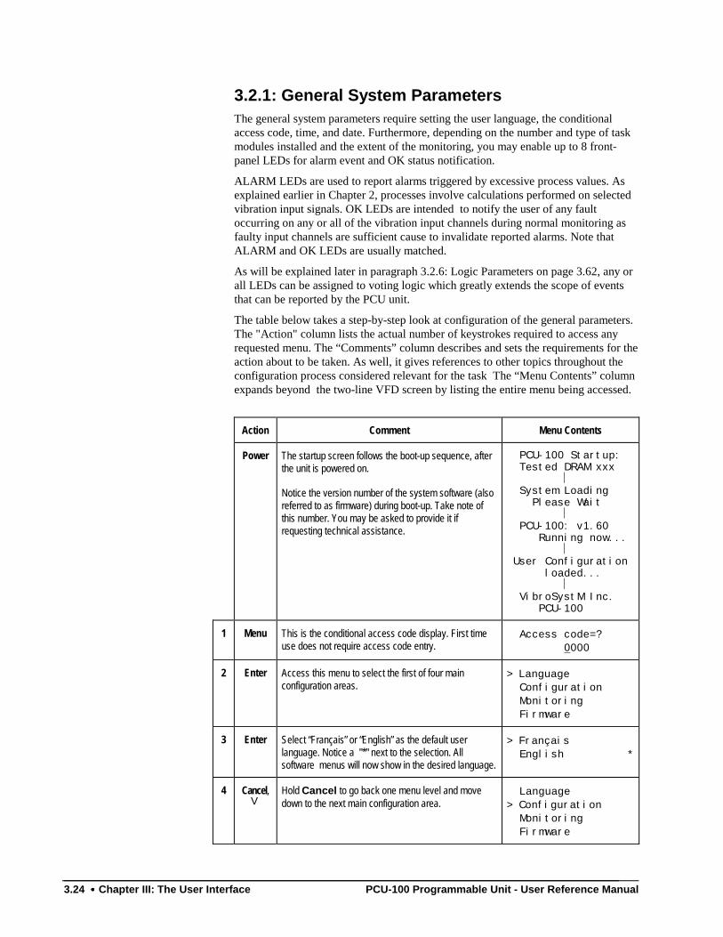
3.24 •••• Chapter III: The User Interface PCU-100 Programmable Unit - User Reference Manual
3.2.1: General System ParametersThe general system parameters require setting the user language, the conditionalaccess code, time, and date. Furthermore, depending on the number and type of taskmodules installed and the extent of the monitoring, you may enable up to 8 front-panel LEDs for alarm event and OK status notification.
ALARM LEDs are used to report alarms triggered by excessive process values. Asexplained earlier in Chapter 2, processes involve calculations performed on selectedvibration input signals. OK LEDs are intended to notify the user of any faultoccurring on any or all of the vibration input channels during normal monitoring asfaulty input channels are sufficient cause to invalidate reported alarms. Note thatALARM and OK LEDs are usually matched.
As will be explained later in paragraph 3.2.6: Logic Parameters on page 3.62, any orall LEDs can be assigned to voting logic which greatly extends the scope of eventsthat can be reported by the PCU unit.
The table below takes a step-by-step look at configuration of the general parameters.The "Action" column lists the actual number of keystrokes required to access anyrequested menu. The “Comments” column describes and sets the requirements for theaction about to be taken. As well, it gives references to other topics throughout theconfiguration process considered relevant for the task The “Menu Contents” columnexpands beyond the two-line VFD screen by listing the entire menu being accessed.
Action Comment Menu Contents
Power The startup screen follows the boot-up sequence, afterthe unit is powered on.
Notice the version number of the system software (alsoreferred to as firmware) during boot-up. Take note ofthis number. You may be asked to provide it ifrequesting technical assistance.
PCU-100 Startup: Tested DRAM xxx System Loading Please Wait PCU-100: v1.60 Running now... User Configuration loaded... VibroSystM Inc. PCU-100
1 Menu This is the conditional access code display. First timeuse does not require access code entry.
Access code=? 0000
2 Enter Access this menu to select the first of four mainconfiguration areas.
> Language Configuration Monitoring Firmware
3 Enter Select “Français” or “English” as the default userlanguage. Notice a "*" next to the selection. Allsoftware menus will now show in the desired language.
> Français English *
4 Cancel,V
Hold Cancel to go back one menu level and movedown to the next main configuration area.
Language> Configuration Monitoring Firmware
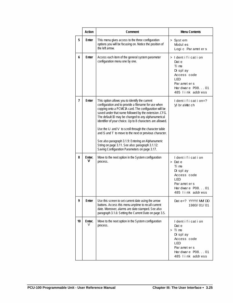
PCU-100 Programmable Unit - User Reference Manual Chapter III: The User Interface •••• 3.25
Action Comment Menu Contents
5 Enter This menu gives access to the three configurationoptions you will be focusing on. Notice the position ofthe left arrow.
> System Modules Logic Parameters
6 Enter Access each item of the general system parameterconfiguration menu one by one.
> Identification Date Time Display Access code LED Parameters Hardware P08...01 485 link address
7 Enter This option allows you to identify the currentconfiguration and to provide a filename for use whencopying onto a PCMCIA card. The configuration will besaved under that name followed by the extension .CFG.The default ID may be changed to any alphanumericalidentifier of your choice. Up to 8 characters are allowed.
Use the U and V to scroll through the character tableand S and T to move to the next or previous character.
See also paragraph 3.1.9: Entering an AlphanumericString on page 3.11. See also: paragraph 3.1.12:Saving Configuration Parameters on page 3.17.
Identification=? VibraWatch
8 Enter,VVVV
Move to the next option in the System configurationprocess.
Identification> Date Time Display Access code LED Parameters Hardware P08...01 485 link address
9 Enter Use this screen to set current date using the arrowbuttons. Access this menu anytime to recall currentdate. Moreover, alarms are date-stamped. See alsoparagraph 3.1.6: Setting the Current Date on page 3.5.
Date=? YYYY/MM/DD 1980/01/01
10 Enter,V
Move to the next option in the System configurationprocess.
Identification Date> Time Display Access code LED Parameters Hardware P08...01 485 link address
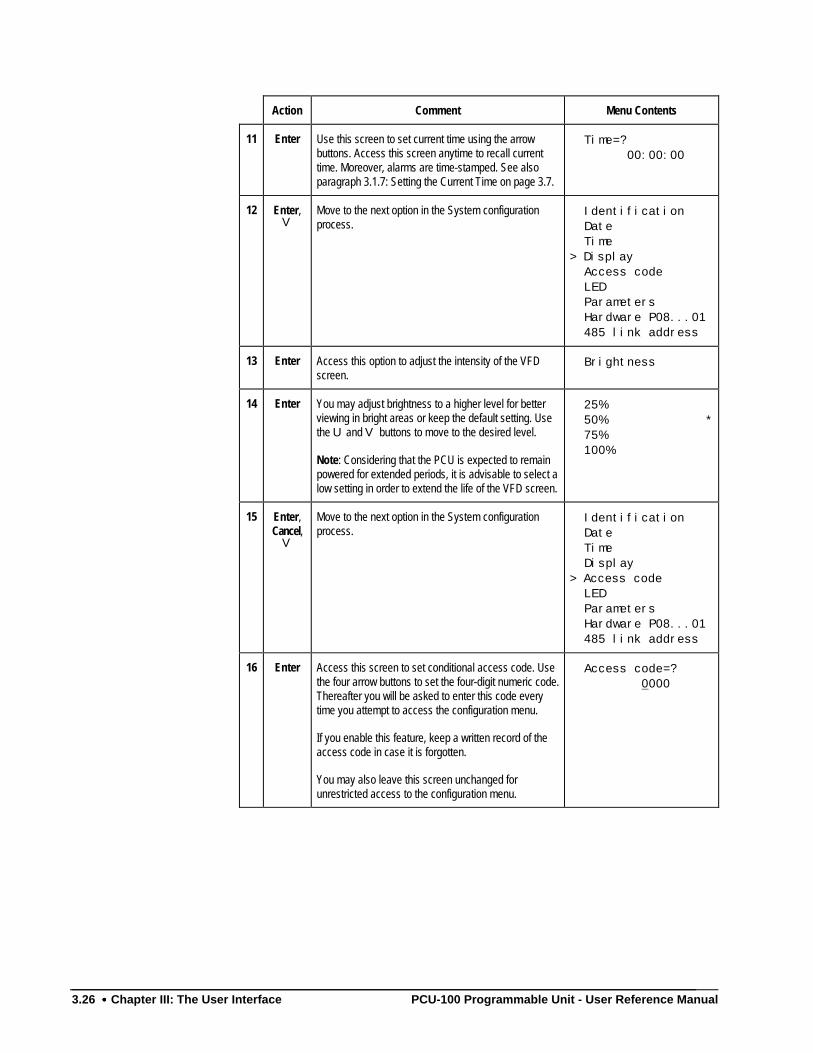
3.26 •••• Chapter III: The User Interface PCU-100 Programmable Unit - User Reference Manual
Action Comment Menu Contents
11 Enter Use this screen to set current time using the arrowbuttons. Access this screen anytime to recall currenttime. Moreover, alarms are time-stamped. See alsoparagraph 3.1.7: Setting the Current Time on page 3.7.
Time=? 00:00:00
12 Enter,V
Move to the next option in the System configurationprocess.
Identification Date Time> Display Access code LED Parameters Hardware P08...01 485 link address
13 Enter Access this option to adjust the intensity of the VFDscreen.
Brightness
14 Enter You may adjust brightness to a higher level for betterviewing in bright areas or keep the default setting. Usethe U and V buttons to move to the desired level.
Note: Considering that the PCU is expected to remainpowered for extended periods, it is advisable to select alow setting in order to extend the life of the VFD screen.
25% 50% * 75% 100%
15 Enter,Cancel,
V
Move to the next option in the System configurationprocess.
Identification Date Time Display> Access code LED Parameters Hardware P08...01 485 link address
16 Enter Access this screen to set conditional access code. Usethe four arrow buttons to set the four-digit numeric code.Thereafter you will be asked to enter this code everytime you attempt to access the configuration menu.
If you enable this feature, keep a written record of theaccess code in case it is forgotten.
You may also leave this screen unchanged forunrestricted access to the configuration menu.
Access code=? 0000
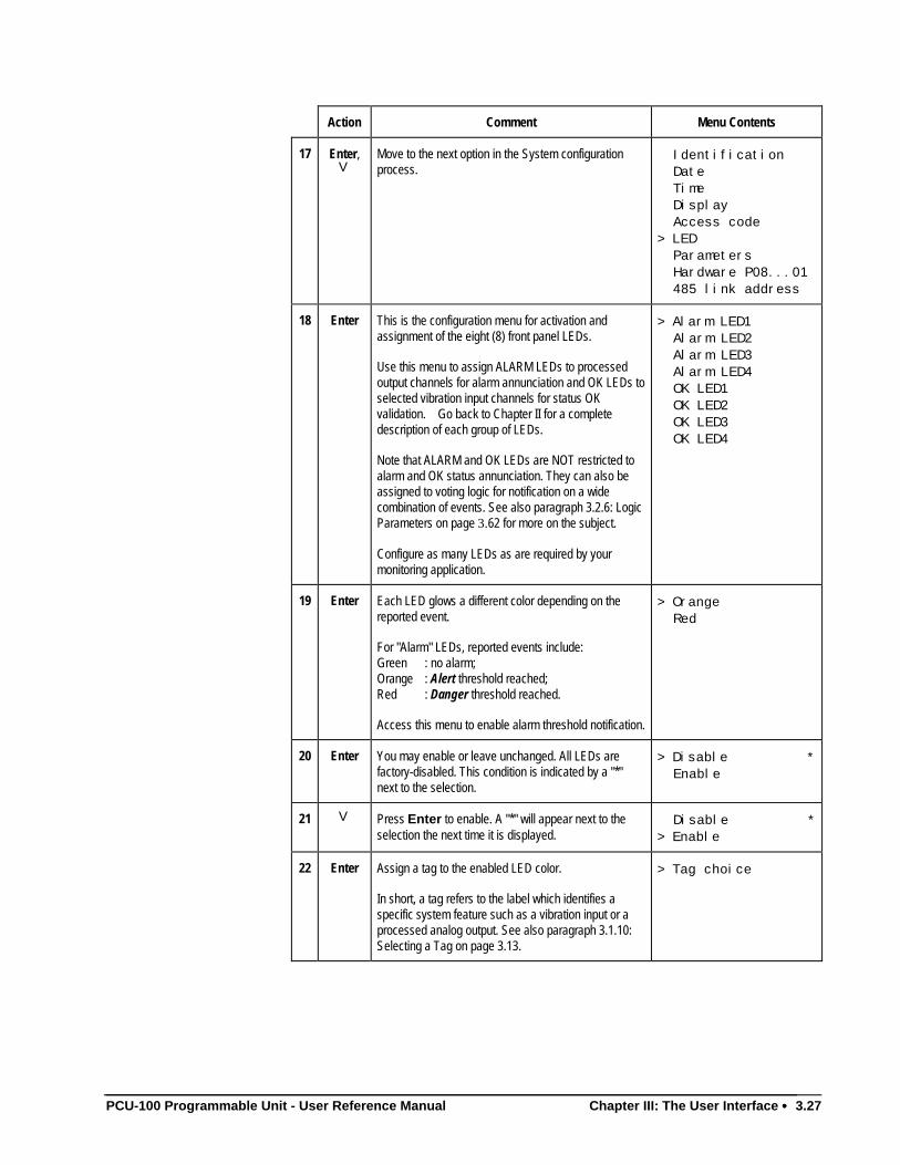
PCU-100 Programmable Unit - User Reference Manual Chapter III: The User Interface •••• 3.27
Action Comment Menu Contents
17 Enter,V
Move to the next option in the System configurationprocess.
Identification Date Time Display Access code> LED Parameters Hardware P08...01 485 link address
18 Enter This is the configuration menu for activation andassignment of the eight (8) front panel LEDs.
Use this menu to assign ALARM LEDs to processedoutput channels for alarm annunciation and OK LEDs toselected vibration input channels for status OKvalidation. Go back to Chapter II for a completedescription of each group of LEDs.
Note that ALARM and OK LEDs are NOT restricted toalarm and OK status annunciation. They can also beassigned to voting logic for notification on a widecombination of events. See also paragraph 3.2.6: LogicParameters on page 3.62 for more on the subject.
Configure as many LEDs as are required by yourmonitoring application.
> Alarm LED1 Alarm LED2 Alarm LED3 Alarm LED4 OK LED1 OK LED2 OK LED3 OK LED4
19 Enter Each LED glows a different color depending on thereported event.
For "Alarm" LEDs, reported events include:Green : no alarm;Orange : Alert threshold reached;Red : Danger threshold reached.
Access this menu to enable alarm threshold notification.
> Orange Red
20 Enter You may enable or leave unchanged. All LEDs arefactory-disabled. This condition is indicated by a "*"next to the selection.
> Disable * Enable
21 V Press Enter to enable. A "*" will appear next to theselection the next time it is displayed.
Disable *> Enable
22 Enter Assign a tag to the enabled LED color.
In short, a tag refers to the label which identifies aspecific system feature such as a vibration input or aprocessed analog output. See also paragraph 3.1.10:Selecting a Tag on page 3.13.
> Tag choice
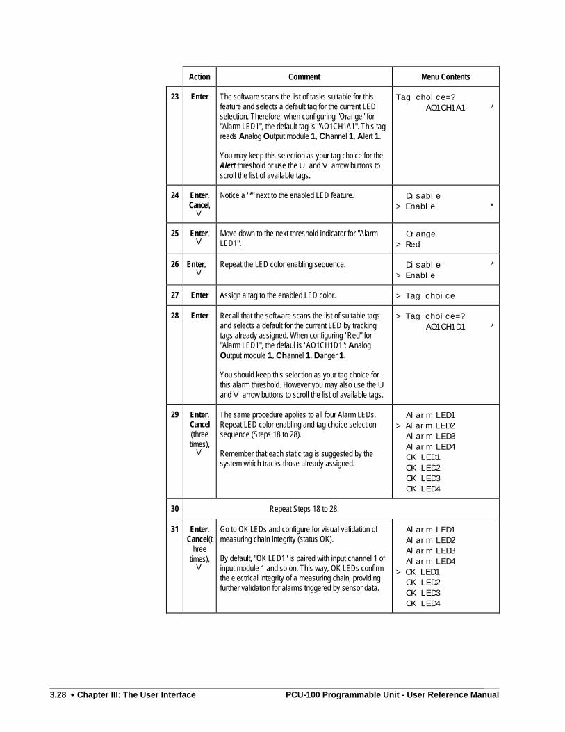
3.28 •••• Chapter III: The User Interface PCU-100 Programmable Unit - User Reference Manual
Action Comment Menu Contents
23 Enter The software scans the list of tasks suitable for thisfeature and selects a default tag for the current LEDselection. Therefore, when configuring "Orange" for"Alarm LED1", the default tag is "AO1CH1A1". This tagreads Analog Output module 1, Channel 1, Alert 1.
You may keep this selection as your tag choice for theAlert threshold or use the U and V arrow buttons toscroll the list of available tags.
Tag choice=? AO1CH1A1 *
24 Enter,Cancel,
V
Notice a "*" next to the enabled LED feature. Disable> Enable *
25 Enter,V
Move down to the next threshold indicator for "AlarmLED1".
Orange> Red
26 Enter,V
Repeat the LED color enabling sequence. Disable *> Enable
27 Enter Assign a tag to the enabled LED color. > Tag choice
28 Enter Recall that the software scans the list of suitable tagsand selects a default for the current LED by trackingtags already assigned. When configuring "Red" for"Alarm LED1", the defaul is "AO1CH1D1": AnalogOutput module 1, Channel 1, Danger 1.
You should keep this selection as your tag choice forthis alarm threshold. However you may also use the Uand V arrow buttons to scroll the list of available tags.
> Tag choice=? AO1CH1D1 *
29 Enter,Cancel(threetimes),
V
The same procedure applies to all four Alarm LEDs.Repeat LED color enabling and tag choice selectionsequence (Steps 18 to 28).
Remember that each static tag is suggested by thesystem which tracks those already assigned.
Alarm LED1> Alarm LED2 Alarm LED3 Alarm LED4 OK LED1 OK LED2 OK LED3 OK LED4
30 Repeat Steps 18 to 28.
31 Enter,Cancel(t
hreetimes),
V
Go to OK LEDs and configure for visual validation ofmeasuring chain integrity (status OK).
By default, "OK LED1" is paired with input channel 1 ofinput module 1 and so on. This way, OK LEDs confirmthe electrical integrity of a measuring chain, providingfurther validation for alarms triggered by sensor data.
Alarm LED1 Alarm LED2 Alarm LED3 Alarm LED4> OK LED1 OK LED2 OK LED3 OK LED4
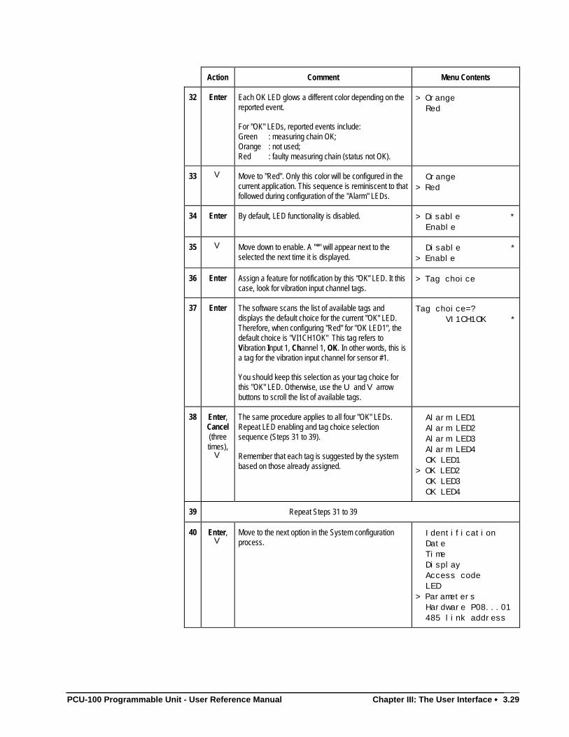
PCU-100 Programmable Unit - User Reference Manual Chapter III: The User Interface •••• 3.29
Action Comment Menu Contents
32 Enter Each OK LED glows a different color depending on thereported event.
For "OK" LEDs, reported events include:Green : measuring chain OK;Orange : not used;Red : faulty measuring chain (status not OK).
> Orange Red
33 V Move to "Red". Only this color will be configured in thecurrent application. This sequence is reminiscent to thatfollowed during configuration of the "Alarm" LEDs.
Orange> Red
34 Enter By default, LED functionality is disabled. > Disable * Enable
35 V Move down to enable. A "*" will appear next to theselected the next time it is displayed.
Disable *> Enable
36 Enter Assign a feature for notification by this “OK” LED. It thiscase, look for vibration input channel tags.
> Tag choice
37 Enter The software scans the list of available tags anddisplays the default choice for the current "OK" LED.Therefore, when configuring "Red" for "OK LED1", thedefault choice is "VI1CH1OK" This tag refers toVibration Input 1, Channel 1, OK. In other words, this isa tag for the vibration input channel for sensor #1.
You should keep this selection as your tag choice forthis "OK" LED. Otherwise, use the U and V arrowbuttons to scroll the list of available tags.
Tag choice=? VI1CH1OK *
38 Enter,Cancel(threetimes),
V
The same procedure applies to all four "OK" LEDs.Repeat LED enabling and tag choice selectionsequence (Steps 31 to 39).
Remember that each tag is suggested by the systembased on those already assigned.
Alarm LED1 Alarm LED2 Alarm LED3 Alarm LED4 OK LED1> OK LED2 OK LED3 OK LED4
39 Repeat Steps 31 to 39
40 Enter,V
Move to the next option in the System configurationprocess.
Identification Date Time Display Access code LED> Parameters Hardware P08...01 485 link address
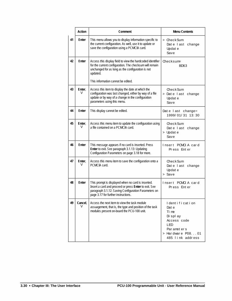
3.30 •••• Chapter III: The User Interface PCU-100 Programmable Unit - User Reference Manual
Action Comment Menu Contents
41 Enter This menu allows you to display information specific tothe current configuration. As well, use it to update orsave the configuration using a PCMCIA card.
> CheckSum Date last change Update Save
42 Enter Access this display field to view the hardcoded identifierfor the current configuration. The checksum will remainunchanged for as long as the configuration is notupdated.
This information cannot be edited.
Checksum= BD63
43 Enter,V
Access this item to display the date at which theconfiguration was last changed, either by way of a fileupdate or by way of a change in the configurationparameters using this menu.
CheckSum> Date last change Update Save
44 Enter This display cannot be edited. Date last change= 1999/01/31 13:30
45 Enter,V
Access this menu item to update the configuration usinga file contained on a PCMCIA card.
CheckSum Date last change> Update Save
46 Enter This message appears if no card is inserted. PressEnter to exit. See paragraph 3.1.13: UpdatingConfiguration Parameters on page 3.18 for more.
Insert PCMCIA card Press Enter
47 Enter,V
Access this menu item to save the configuration onto aPCMCIA card.
CheckSum Date last change Update> Save
48 Enter This prompt is displayed when no card is inserted.Insert a card and proceed or press Enter to exit. Seeparagraph 3.1.12: Saving Configuration Parameters onpage 3.17 for further instructions.
Insert PCMCIA card Press Enter
49 Cancel,V
Access the next item to view the task moduleassuagement, that is, the type and position of the taskmodules present on-board the PCU-100 unit.
Identification Date Time Display Access code LED Parameters> Hardware P08...01 485 link address
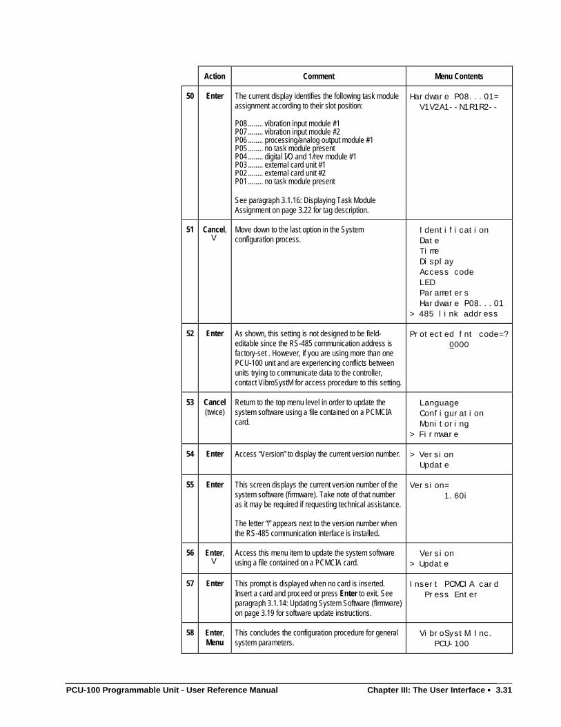
PCU-100 Programmable Unit - User Reference Manual Chapter III: The User Interface •••• 3.31
Action Comment Menu Contents
50 Enter The current display identifies the following task moduleassignment according to their slot position:
P08 ........ vibration input module #1P07 ........ vibration input module #2P06 ........ processing/analog output module #1P05 ........ no task module presentP04 ........ digital I/O and 1/rev module #1P03 ........ external card unit #1P02 ........ external card unit #2P01 ........ no task module present
See paragraph 3.1.16: Displaying Task ModuleAssignment on page 3.22 for tag description.
Hardware P08...01= V1V2A1--N1R1R2--
51 Cancel,V
Move down to the last option in the Systemconfiguration process.
Identification Date Time Display Access code LED Parameters Hardware P08...01> 485 link address
52 Enter As shown, this setting is not designed to be field-editable since the RS-485 communication address isfactory-set . However, if you are using more than onePCU-100 unit and are experiencing conflicts betweenunits trying to communicate data to the controller,contact VibroSystM for access procedure to this setting.
Protected fnt code=? 0000
53 Cancel(twice)
Return to the top menu level in order to update thesystem software using a file contained on a PCMCIAcard.
Language Configuration Monitoring> Firmware
54 Enter Access “Version” to display the current version number. > Version Update
55 Enter This screen displays the current version number of thesystem software (firmware). Take note of that numberas it may be required if requesting technical assistance.
The letter “i” appears next to the version number whenthe RS-485 communication interface is installed.
Version= 1.60i
56 Enter,V
Access this menu item to update the system softwareusing a file contained on a PCMCIA card.
Version> Update
57 Enter This prompt is displayed when no card is inserted.Insert a card and proceed or press Enter to exit. Seeparagraph 3.1.14: Updating System Software (firmware)on page 3.19 for software update instructions.
Insert PCMCIA card Press Enter
58 Enter,Menu
This concludes the configuration procedure for generalsystem parameters.
VibroSystM Inc. PCU-100
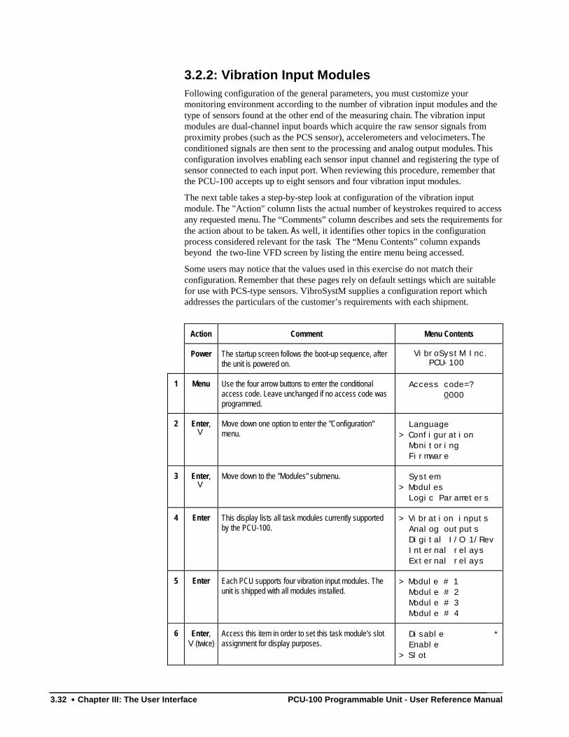
3.32 •••• Chapter III: The User Interface PCU-100 Programmable Unit - User Reference Manual
3.2.2: Vibration Input ModulesFollowing configuration of the general parameters, you must customize yourmonitoring environment according to the number of vibration input modules and thetype of sensors found at the other end of the measuring chain. The vibration inputmodules are dual-channel input boards which acquire the raw sensor signals fromproximity probes (such as the PCS sensor), accelerometers and velocimeters. Theconditioned signals are then sent to the processing and analog output modules. Thisconfiguration involves enabling each sensor input channel and registering the type ofsensor connected to each input port. When reviewing this procedure, remember thatthe PCU-100 accepts up to eight sensors and four vibration input modules.
The next table takes a step-by-step look at configuration of the vibration inputmodule. The "Action" column lists the actual number of keystrokes required to accessany requested menu. The “Comments” column describes and sets the requirements forthe action about to be taken. As well, it identifies other topics in the configurationprocess considered relevant for the task The “Menu Contents” column expandsbeyond the two-line VFD screen by listing the entire menu being accessed.
Some users may notice that the values used in this exercise do not match theirconfiguration. Remember that these pages rely on default settings which are suitablefor use with PCS-type sensors. VibroSystM supplies a configuration report whichaddresses the particulars of the customer’s requirements with each shipment.
Action Comment Menu Contents
Power The startup screen follows the boot-up sequence, afterthe unit is powered on.
VibroSystM Inc. PCU-100
1 Menu Use the four arrow buttons to enter the conditionalaccess code. Leave unchanged if no access code wasprogrammed.
Access code=? 0000
2 Enter,V
Move down one option to enter the "Configuration"menu.
Language> Configuration Monitoring Firmware
3 Enter,V
Move down to the "Modules" submenu. System> Modules Logic Parameters
4 Enter This display lists all task modules currently supportedby the PCU-100.
> Vibration inputs Analog outputs Digital I/O 1/Rev Internal relays External relays
5 Enter Each PCU supports four vibration input modules. Theunit is shipped with all modules installed.
> Module # 1 Module # 2 Module # 3 Module # 4
6 Enter,V(twice)
Access this item in order to set this task module’s slotassignment for display purposes.
Disable * Enable> Slot
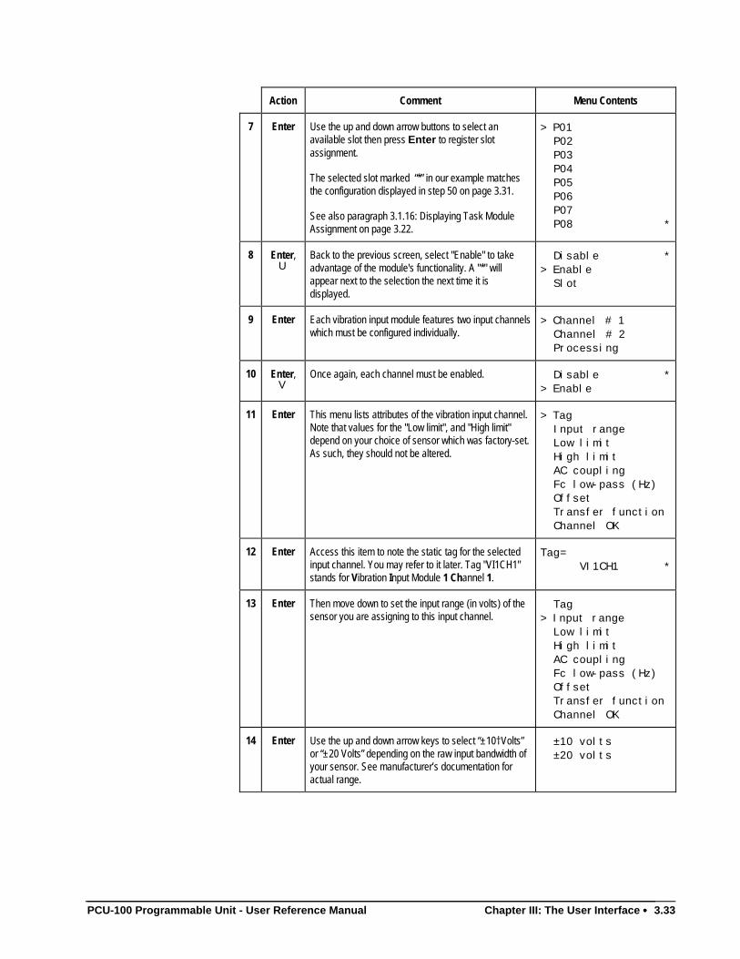
PCU-100 Programmable Unit - User Reference Manual Chapter III: The User Interface •••• 3.33
Action Comment Menu Contents
7 Enter Use the up and down arrow buttons to select anavailable slot then press Enter to register slotassignment.
The selected slot marked “*” in our example matchesthe configuration displayed in step 50 on page 3.31.
See also paragraph 3.1.16: Displaying Task ModuleAssignment on page 3.22.
> P01 P02 P03 P04 P05 P06 P07 P08 *
8 Enter,U
Back to the previous screen, select "Enable" to takeadvantage of the module's functionality. A "*" willappear next to the selection the next time it isdisplayed.
Disable *> Enable Slot
9 Enter Each vibration input module features two input channelswhich must be configured individually.
> Channel # 1 Channel # 2 Processing
10 Enter,V
Once again, each channel must be enabled. Disable *> Enable
11 Enter This menu lists attributes of the vibration input channel.Note that values for the "Low limit", and "High limit"depend on your choice of sensor which was factory-set.As such, they should not be altered.
> Tag Input range Low limit High limit AC coupling Fc low-pass (Hz) Offset Transfer function Channel OK
12 Enter Access this item to note the static tag for the selectedinput channel. You may refer to it later. Tag "VI1CH1"stands for Vibration Input Module 1 Channel 1.
Tag= VI1CH1 *
13 Enter Then move down to set the input range (in volts) of thesensor you are assigning to this input channel.
Tag> Input range Low limit High limit AC coupling Fc low-pass (Hz) Offset Transfer function Channel OK
14 Enter Use the up and down arrow keys to select “±10†Volts”or “±20 Volts” depending on the raw input bandwidth ofyour sensor. See manufacturer’s documentation foractual range.
±10 volts ±20 volts
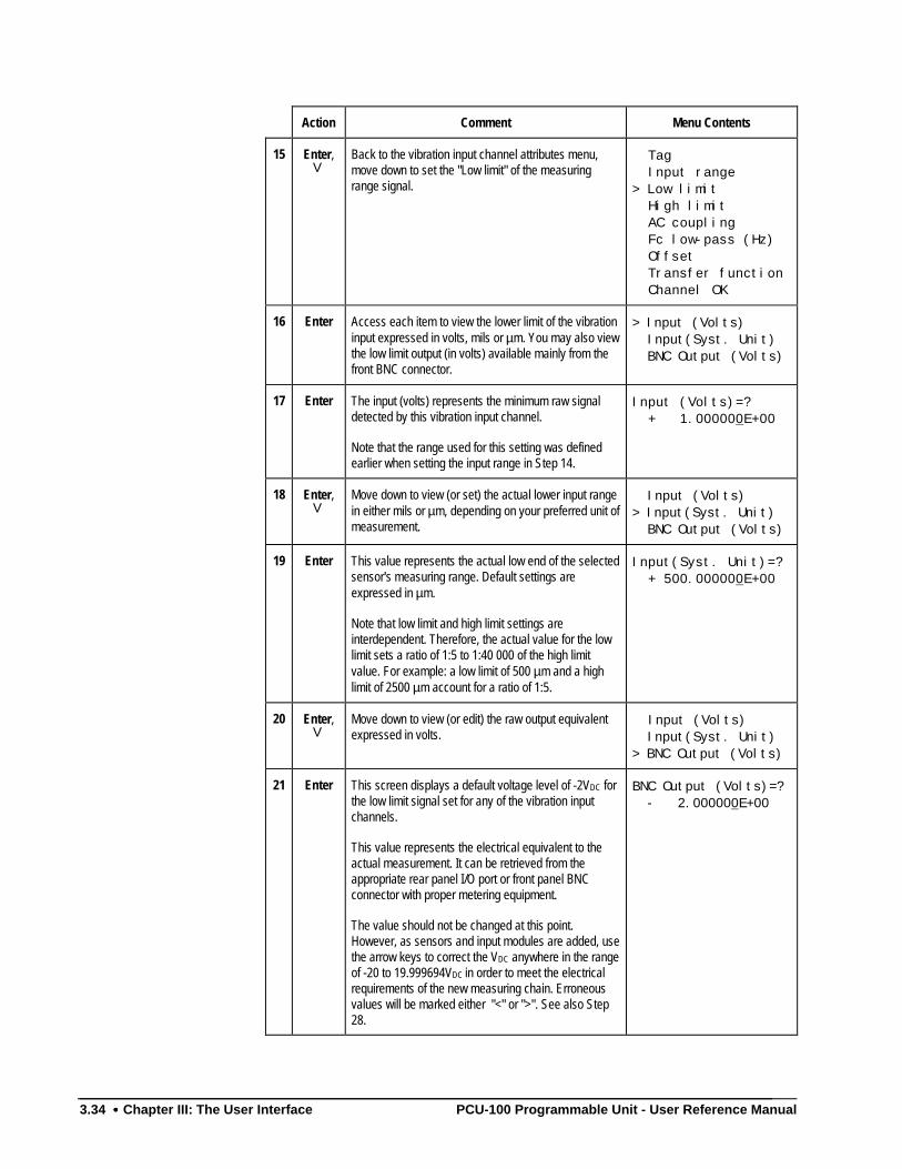
3.34 •••• Chapter III: The User Interface PCU-100 Programmable Unit - User Reference Manual
Action Comment Menu Contents
15 Enter,V
Back to the vibration input channel attributes menu,move down to set the "Low limit" of the measuringrange signal.
Tag Input range> Low limit High limit AC coupling Fc low-pass (Hz) Offset Transfer function Channel OK
16 Enter Access each item to view the lower limit of the vibrationinput expressed in volts, mils or µm. You may also viewthe low limit output (in volts) available mainly from thefront BNC connector.
> Input (Volts) Input(Syst. Unit) BNC Output (Volts)
17 Enter The input (volts) represents the minimum raw signaldetected by this vibration input channel.
Note that the range used for this setting was definedearlier when setting the input range in Step 14.
Input (Volts)=? + 1.000000E+00
18 Enter,V
Move down to view (or set) the actual lower input rangein either mils or µm, depending on your preferred unit ofmeasurement.
Input (Volts)> Input(Syst. Unit) BNC Output (Volts)
19 Enter This value represents the actual low end of the selectedsensor's measuring range. Default settings areexpressed in µm.
Note that low limit and high limit settings areinterdependent. Therefore, the actual value for the lowlimit sets a ratio of 1:5 to 1:40 000 of the high limitvalue. For example: a low limit of 500 µm and a highlimit of 2500 µm account for a ratio of 1:5.
Input(Syst. Unit)=? + 500.000000E+00
20 Enter,V
Move down to view (or edit) the raw output equivalentexpressed in volts.
Input (Volts) Input(Syst. Unit)> BNC Output (Volts)
21 Enter This screen displays a default voltage level of -2VDC forthe low limit signal set for any of the vibration inputchannels.
This value represents the electrical equivalent to theactual measurement. It can be retrieved from theappropriate rear panel I/O port or front panel BNCconnector with proper metering equipment.
The value should not be changed at this point.However, as sensors and input modules are added, usethe arrow keys to correct the VDC anywhere in the rangeof -20 to 19.999694VDC in order to meet the electricalrequirements of the new measuring chain. Erroneousvalues will be marked either "<" or ">". See also Step28.
BNC Output (Volts)=? - 2.000000E+00
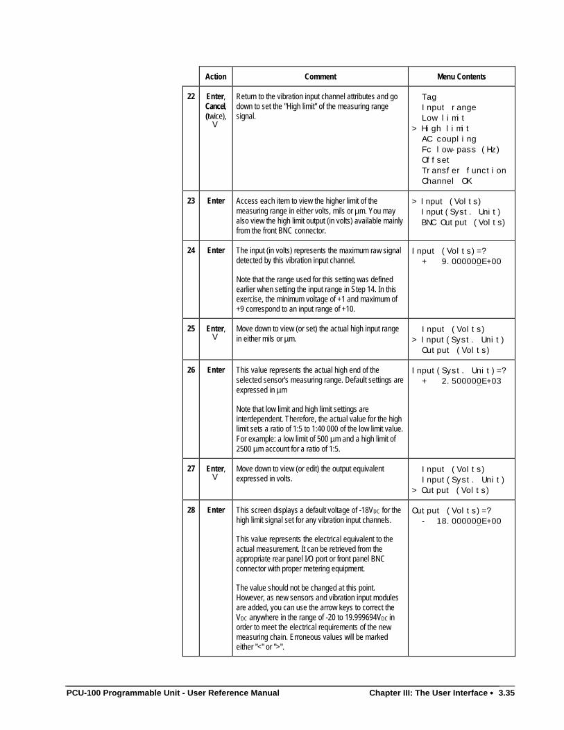
PCU-100 Programmable Unit - User Reference Manual Chapter III: The User Interface •••• 3.35
Action Comment Menu Contents
22 Enter,Cancel,(twice),
V
Return to the vibration input channel attributes and godown to set the "High limit" of the measuring rangesignal.
Tag Input range Low limit> High limit AC coupling Fc low-pass (Hz) Offset Transfer function Channel OK
23 Enter Access each item to view the higher limit of themeasuring range in either volts, mils or µm. You mayalso view the high limit output (in volts) available mainlyfrom the front BNC connector.
> Input (Volts) Input(Syst. Unit) BNC Output (Volts)
24 Enter The input (in volts) represents the maximum raw signaldetected by this vibration input channel.
Note that the range used for this setting was definedearlier when setting the input range in Step 14. In thisexercise, the minimum voltage of +1 and maximum of+9 correspond to an input range of +10.
Input (Volts)=? + 9.000000E+00
25 Enter,V
Move down to view (or set) the actual high input rangein either mils or µm.
Input (Volts)> Input(Syst. Unit) Output (Volts)
26 Enter This value represents the actual high end of theselected sensor's measuring range. Default settings areexpressed in µm
Note that low limit and high limit settings areinterdependent. Therefore, the actual value for the highlimit sets a ratio of 1:5 to 1:40 000 of the low limit value.For example: a low limit of 500 µm and a high limit of2500 µm account for a ratio of 1:5.
Input(Syst. Unit)=? + 2.500000E+03
27 Enter,V
Move down to view (or edit) the output equivalentexpressed in volts.
Input (Volts) Input(Syst. Unit)> Output (Volts)
28 Enter This screen displays a default voltage of -18VDC for thehigh limit signal set for any vibration input channels.
This value represents the electrical equivalent to theactual measurement. It can be retrieved from theappropriate rear panel I/O port or front panel BNCconnector with proper metering equipment.
The value should not be changed at this point.However, as new sensors and vibration input modulesare added, you can use the arrow keys to correct theVDC anywhere in the range of -20 to 19.999694VDC inorder to meet the electrical requirements of the newmeasuring chain. Erroneous values will be markedeither "<" or ">".
Output (Volts)=? - 18.000000E+00
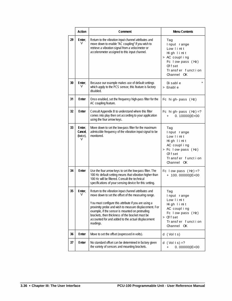
3.36 •••• Chapter III: The User Interface PCU-100 Programmable Unit - User Reference Manual
Action Comment Menu Contents
29 Enter,V
Return to the vibration input channel attributes andmove down to enable "AC coupling" if you wish toretrieve a vibration signal from a velocimeter oraccelerometer assigned to this input channel.
Tag Input range Low limit High limit> AC coupling Fc low-pass (Hz) Offset Transfer function Channel OK
30 Enter,V
Because our example makes use of default settingswhich apply to the PCS sensor, this feature is factorydisabled.
Disable *> Enable
31 Enter Once enabled, set the frequency high-pass filter for theAC coupling feature.
Fc high-pass (Hz)
32 Enter Consult Appendix B to understand where this filtercomes into play then set according to your applicationusing the four arrow keys.
Fc high-pass (Hz)=? + 0.100000E+00
33 Enter,Cancel,(twice),
V
Move down to set the low-pass filter for the maximumadmissible frequency of the vibration input signal to bemonitored.
Tag Input range Low limit High limit AC coupling> Fc low-pass (Hz) Offset Transfer function Channel OK
34 Enter Use the four arrow keys to set the low-pass filter. The100 Hz default setting means that vibration higher than100 Hz will be filtered. Consult the technicalspecifications of your sensing device for this setting.
Fc low-pass (Hz)=? + 100.000000E+00
35 Enter,V
Return to the vibration input channel attributes andmove down to set the offset of the measuring range.
You must configure this attribute if you are using aproximity probe and wish to measure displacement. Forexample, if the sensor is mounted on protrudingbrackets, then thickness of the bracket must beaccounted for and added to the actual displacementreadings.
Tag Input range Low limit High limit AC coupling Fc low-pass (Hz)> Offset Transfer function Channel OK
36 Enter Move to set the offset (expressed in volts). d (Volts)
37 Enter No standard offset can be determined in factory giventhe variety of sensors and mounting brackets.
d (Volts)=? + 0.000000E+00
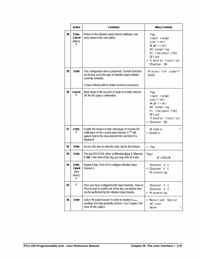
PCU-100 Programmable Unit - User Reference Manual Chapter III: The User Interface •••• 3.37
Action Comment Menu Contents
38 Enter,Cancel(twice),
V
Return to the vibration input channel attributes andmove down to the next option.
Tag Input range Low limit High limit AC coupling Fc low-pass (Hz) Offset> Transfer function Channel OK
39 Enter This configuration item is protected. Transfer functionsare factory-set to the type of vibration input modulescurrently available.
Contact VibroSystM for further technical assistance.
Protect fnt code=? 0000
40 Cancel,V
Move down to the last item in order to enable channelOK for OK status confirmation.
Tag Input range Low limit High limit AC coupling Fc low-pass (Hz) Offset Transfer function> Channel OK
41 Enter,V
Enable this feature to take advantage of channel OKnotification on the current input channel. A "*" willappear next to the new selection the next time it isdisplayed.
Disable *> Enable
42 Enter Access this item to view the static tag for this feature. > Tag
43 Enter The tag VI1CH1OK refers to Vibration Input 1, Channel1, OK. Take note of this tag, you may refer to it later.
Tag= VI1CH1OK
44 Enter,Cancel(four
times),V
Repeat Steps 10 to 43 to configure vibration inputchannel 2.
Channel # 1> Channel # 2 Processing
45 V Once you have configured both input channels, move to“Processing” to enable one of the two calculations thatcan be performed by the vibration input module.
Channel # 1 Channel # 2> Processing
46 Enter Select “Resultant Vector” in order to monitor Svector
readings from two proximity sensors. See Chapter 2 formore on the subject.
> Resultant Vector AC sum None *
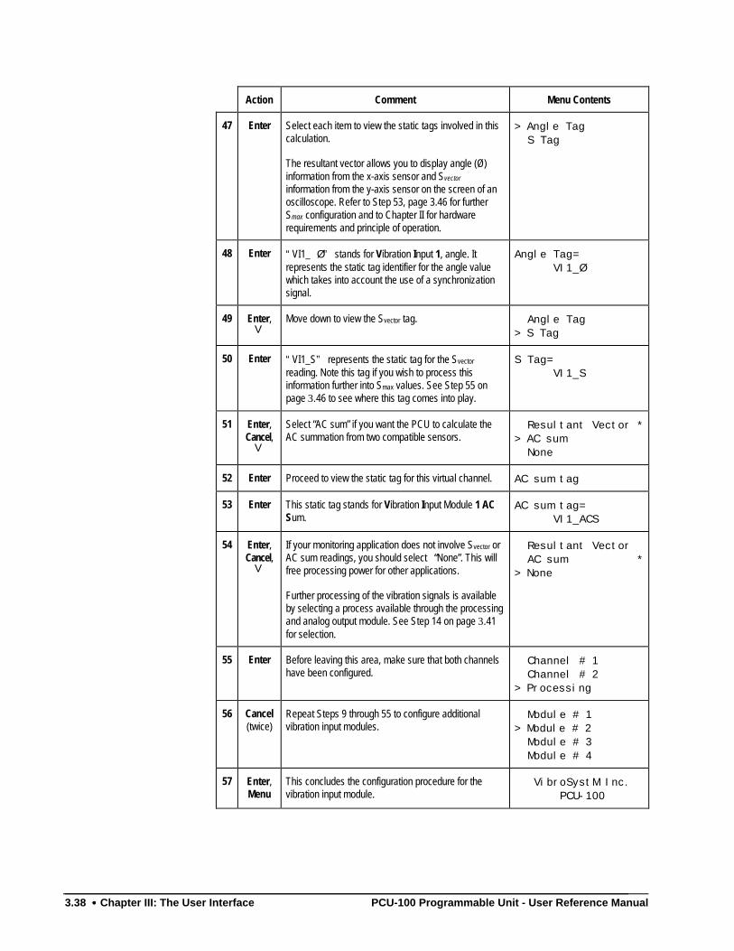
3.38 •••• Chapter III: The User Interface PCU-100 Programmable Unit - User Reference Manual
Action Comment Menu Contents
47 Enter Select each item to view the static tags involved in thiscalculation.
The resultant vector allows you to display angle (Ø)information from the x-axis sensor and Svector
information from the y-axis sensor on the screen of anoscilloscope. Refer to Step 53, page 3.46 for furtherSmax configuration and to Chapter II for hardwarerequirements and principle of operation.
> Angle Tag S Tag
48 Enter “VI1_ Ø” stands for Vibration Input 1, angle. Itrepresents the static tag identifier for the angle valuewhich takes into account the use of a synchronizationsignal.
Angle Tag= VI1_Ø
49 Enter,V
Move down to view the Svector tag. Angle Tag> S Tag
50 Enter “VI1_S” represents the static tag for the Svector
reading. Note this tag if you wish to process thisinformation further into Smax values. See Step 55 onpage 3.46 to see where this tag comes into play.
S Tag= VI1_S
51 Enter,Cancel,
V
Select “AC sum” if you want the PCU to calculate theAC summation from two compatible sensors.
Resultant Vector *> AC sum None
52 Enter Proceed to view the static tag for this virtual channel. AC sum tag
53 Enter This static tag stands for Vibration Input Module 1 ACSum.
AC sum tag= VI1_ACS
54 Enter,Cancel,
V
If your monitoring application does not involve Svector orAC sum readings, you should select “None”. This willfree processing power for other applications.
Further processing of the vibration signals is availableby selecting a process available through the processingand analog output module. See Step 14 on page 3.41for selection.
Resultant Vector AC sum *> None
55 Enter Before leaving this area, make sure that both channelshave been configured.
Channel # 1 Channel # 2> Processing
56 Cancel(twice)
Repeat Steps 9 through 55 to configure additionalvibration input modules.
Module # 1> Module # 2 Module # 3 Module # 4
57 Enter,Menu
This concludes the configuration procedure for thevibration input module.
VibroSystM Inc. PCU-100
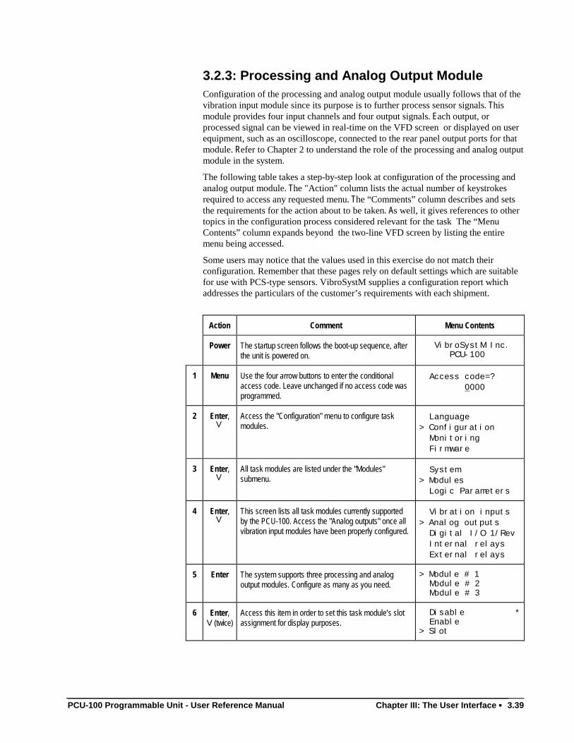
PCU-100 Programmable Unit - User Reference Manual Chapter III: The User Interface •••• 3.39
3.2.3: Processing and Analog Output ModuleConfiguration of the processing and analog output module usually follows that of thevibration input module since its purpose is to further process sensor signals. Thismodule provides four input channels and four output signals. Each output, orprocessed signal can be viewed in real-time on the VFD screen or displayed on userequipment, such as an oscilloscope, connected to the rear panel output ports for thatmodule. Refer to Chapter 2 to understand the role of the processing and analog outputmodule in the system.
The following table takes a step-by-step look at configuration of the processing andanalog output module. The "Action" column lists the actual number of keystrokesrequired to access any requested menu. The “Comments” column describes and setsthe requirements for the action about to be taken. As well, it gives references to othertopics in the configuration process considered relevant for the task The “MenuContents” column expands beyond the two-line VFD screen by listing the entiremenu being accessed.
Some users may notice that the values used in this exercise do not match theirconfiguration. Remember that these pages rely on default settings which are suitablefor use with PCS-type sensors. VibroSystM supplies a configuration report whichaddresses the particulars of the customer’s requirements with each shipment.
Action Comment Menu Contents
Power The startup screen follows the boot-up sequence, afterthe unit is powered on.
VibroSystM Inc. PCU-100
1 Menu Use the four arrow buttons to enter the conditionalaccess code. Leave unchanged if no access code wasprogrammed.
Access code=? 0000
2 Enter,V
Access the "Configuration" menu to configure taskmodules.
Language> Configuration Monitoring Firmware
3 Enter,V
All task modules are listed under the "Modules"submenu.
System> Modules Logic Parameters
4 Enter,V
This screen lists all task modules currently supportedby the PCU-100. Access the "Analog outputs" once allvibration input modules have been properly configured.
Vibration inputs> Analog outputs Digital I/O 1/Rev Internal relays External relays
5 Enter The system supports three processing and analogoutput modules. Configure as many as you need.
> Module # 1 Module # 2 Module # 3
6 Enter,V(twice)
Access this item in order to set this task module’s slotassignment for display purposes.
Disable * Enable> Slot
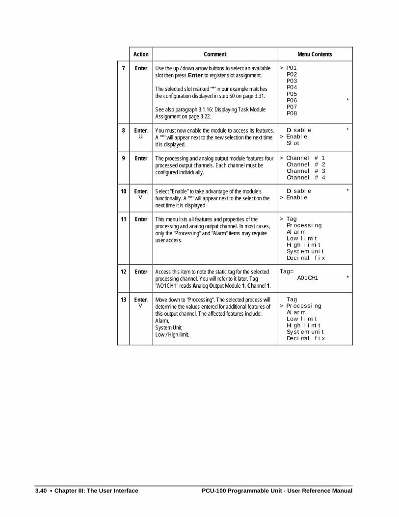
3.40 •••• Chapter III: The User Interface PCU-100 Programmable Unit - User Reference Manual
Action Comment Menu Contents
7 Enter Use the up / down arrow buttons to select an availableslot then press Enter to register slot assignment.
The selected slot marked “*” in our example matchesthe configuration displayed in step 50 on page 3.31.
See also paragraph 3.1.16: Displaying Task ModuleAssignment on page 3.22.
> P01 P02 P03 P04 P05 P06 * P07 P08
8 Enter,U
You must now enable the module to access its features.A "*" will appear next to the new selection the next timeit is displayed.
Disable *> Enable Slot
9 Enter The processing and analog output module features fourprocessed output channels. Each channel must beconfigured individually.
> Channel # 1 Channel # 2 Channel # 3 Channel # 4
10 Enter,V
Select "Enable" to take advantage of the module'sfunctionality. A "*" will appear next to the selection thenext time it is displayed
Disable *> Enable
11 Enter This menu lists all features and properties of theprocessing and analog output channel. In most cases,only the "Processing" and "Alarm" items may requireuser access.
> Tag Processing Alarm Low limit High limit System unit Decimal fix
12 Enter Access this item to note the static tag for the selectedprocessing channel. You will refer to it later. Tag"AO1CH1" reads Analog Output Module 1, Channel 1.
Tag= A01CH1 *
13 Enter,V
Move down to "Processing". The selected process willdetermine the values entered for additional features ofthis output channel. The affected features include:Alarm,System Unit,Low / High limit.
Tag> Processing Alarm Low limit High limit System unit Decimal fix
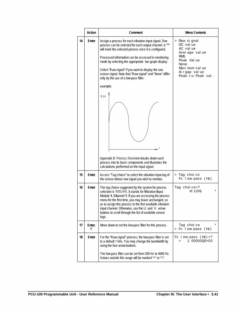
PCU-100 Programmable Unit - User Reference Manual Chapter III: The User Interface •••• 3.41
Action Comment Menu Contents
14 Enter Assign a process for each vibration input signal. Oneprocess can be selected for each output channel. A "*"will mark the selected process once it is configured.
Processed information can be accessed in monitoringmode by selecting the appropriate bar graph display.
Select "Raw signal" if you want to display the rawsensor signal. Note that "Raw signal" and "None" differonly by the use of a low-pass filter.
example:
t
X (t)
Appendix B: Process Overview breaks down eachprocess into its basic components and illustrates thecalculations performed on the input signal.
> Raw signal DC value AC value Average value RMS Peak Value None Maximum value Airgap value Peak-to-Peak val.
15 Enter Access "Tag choice" to select the vibration input tag ofthe sensor whose raw signal you wish to monitor.
> Tag choice Fc low-pass (Hz)
16 Enter The tag choice suggested by the system for processselection is “VI1CH1!. It stands for Vibration InputModule 1, Channel 1. If you are accessing the processmenu for the first time, you may leave unchanged, soas to assign this process to the first available vibrationinput channel. Otherwise, use the U and V arrowbuttons to scroll through the list of available sensortags.
Tag choice=? VI1CH1 *
17 Enter,V
Move down to set the low-pass filter for this process. Tag choice *> Fc low-pass (Hz)
18 Enter For the "Raw signal" process, the low-pass filter is setto a default 1 kHz. You may change the bandwidth byusing the four arrow buttons.
The low-pass filter can be set from 200 Hz to 4000 Hz.Values outside this range will be marked "<" or ">".
Fc low-pass (Hz)=? + 1.000000E+03
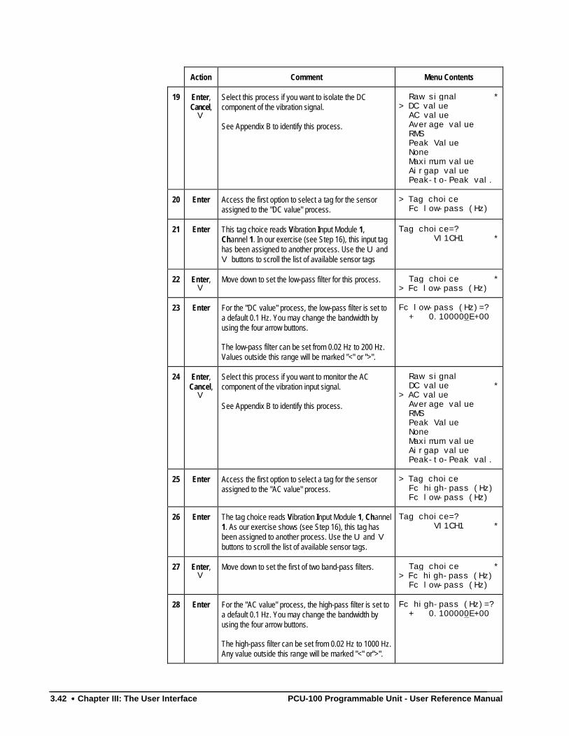
3.42 •••• Chapter III: The User Interface PCU-100 Programmable Unit - User Reference Manual
Action Comment Menu Contents
19 Enter,Cancel,
V
Select this process if you want to isolate the DCcomponent of the vibration signal.
See Appendix B to identify this process.
Raw signal *> DC value AC value Average value RMS Peak Value None Maximum value Airgap value Peak-to-Peak val.
20 Enter Access the first option to select a tag for the sensorassigned to the "DC value" process.
> Tag choice Fc low-pass (Hz)
21 Enter This tag choice reads Vibration Input Module 1,Channel 1. In our exercise (see Step 16), this input taghas been assigned to another process. Use the U andV buttons to scroll the list of available sensor tags
Tag choice=? VI1CH1 *
22 Enter,V
Move down to set the low-pass filter for this process. Tag choice *> Fc low-pass (Hz)
23 Enter For the "DC value" process, the low-pass filter is set toa default 0.1 Hz. You may change the bandwidth byusing the four arrow buttons.
The low-pass filter can be set from 0.02 Hz to 200 Hz.Values outside this range will be marked "<" or ">".
Fc low-pass (Hz)=? + 0.100000E+00
24 Enter,Cancel,
V
Select this process if you want to monitor the ACcomponent of the vibration input signal.
See Appendix B to identify this process.
Raw signal DC value *
> AC value Average value RMS Peak Value None Maximum value Airgap value Peak-to-Peak val.
25 Enter Access the first option to select a tag for the sensorassigned to the "AC value" process.
> Tag choice Fc high-pass (Hz) Fc low-pass (Hz)
26 Enter The tag choice reads Vibration Input Module 1, Channel1. As our exercise shows (see Step 16), this tag hasbeen assigned to another process. Use the U and Vbuttons to scroll the list of available sensor tags.
Tag choice=? VI1CH1 *
27 Enter,V
Move down to set the first of two band-pass filters. Tag choice *> Fc high-pass (Hz) Fc low-pass (Hz)
28 Enter For the "AC value" process, the high-pass filter is set toa default 0.1 Hz. You may change the bandwidth byusing the four arrow buttons.
The high-pass filter can be set from 0.02 Hz to 1000 Hz.Any value outside this range will be marked "<" or">".
Fc high-pass (Hz)=? + 0.100000E+00
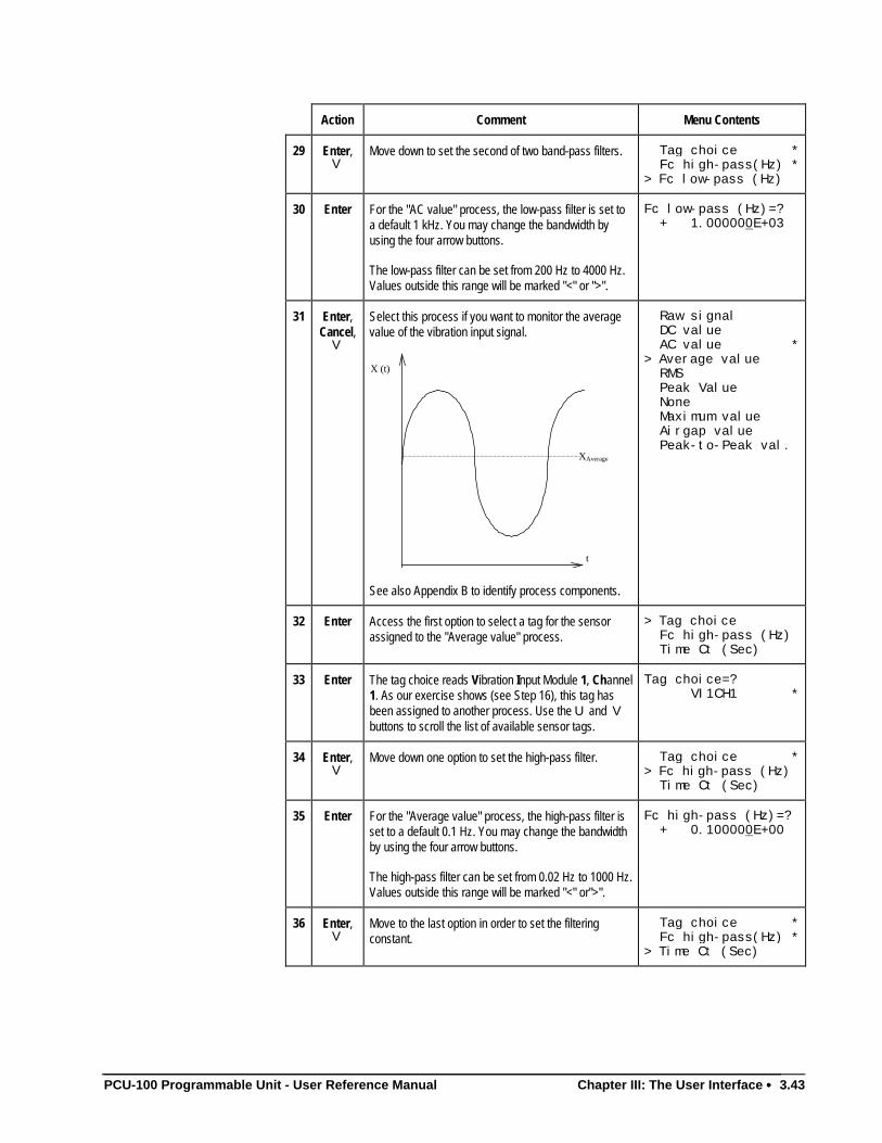
PCU-100 Programmable Unit - User Reference Manual Chapter III: The User Interface •••• 3.43
Action Comment Menu Contents
29 Enter,V
Move down to set the second of two band-pass filters. Tag choice * Fc high-pass(Hz) *> Fc low-pass (Hz)
30 Enter For the "AC value" process, the low-pass filter is set toa default 1 kHz. You may change the bandwidth byusing the four arrow buttons.
The low-pass filter can be set from 200 Hz to 4000 Hz.Values outside this range will be marked "<" or ">".
Fc low-pass (Hz)=? + 1.000000E+03
31 Enter,Cancel,
V
Select this process if you want to monitor the averagevalue of the vibration input signal.
XAverage
t
X (t)
See also Appendix B to identify process components.
Raw signal DC value AC value *> Average value RMS Peak Value None Maximum value Airgap value Peak-to-Peak val.
32 Enter Access the first option to select a tag for the sensorassigned to the "Average value" process.
> Tag choice Fc high-pass (Hz) Time Ct (Sec)
33 Enter The tag choice reads Vibration Input Module 1, Channel1. As our exercise shows (see Step 16), this tag hasbeen assigned to another process. Use the U and Vbuttons to scroll the list of available sensor tags.
Tag choice=? VI1CH1 *
34 Enter,V
Move down one option to set the high-pass filter. Tag choice *> Fc high-pass (Hz) Time Ct (Sec)
35 Enter For the "Average value" process, the high-pass filter isset to a default 0.1 Hz. You may change the bandwidthby using the four arrow buttons.
The high-pass filter can be set from 0.02 Hz to 1000 Hz.Values outside this range will be marked "<" or">".
Fc high-pass (Hz)=? + 0.100000E+00
36 Enter,V
Move to the last option in order to set the filteringconstant.
Tag choice * Fc high-pass(Hz) *> Time Ct (Sec)
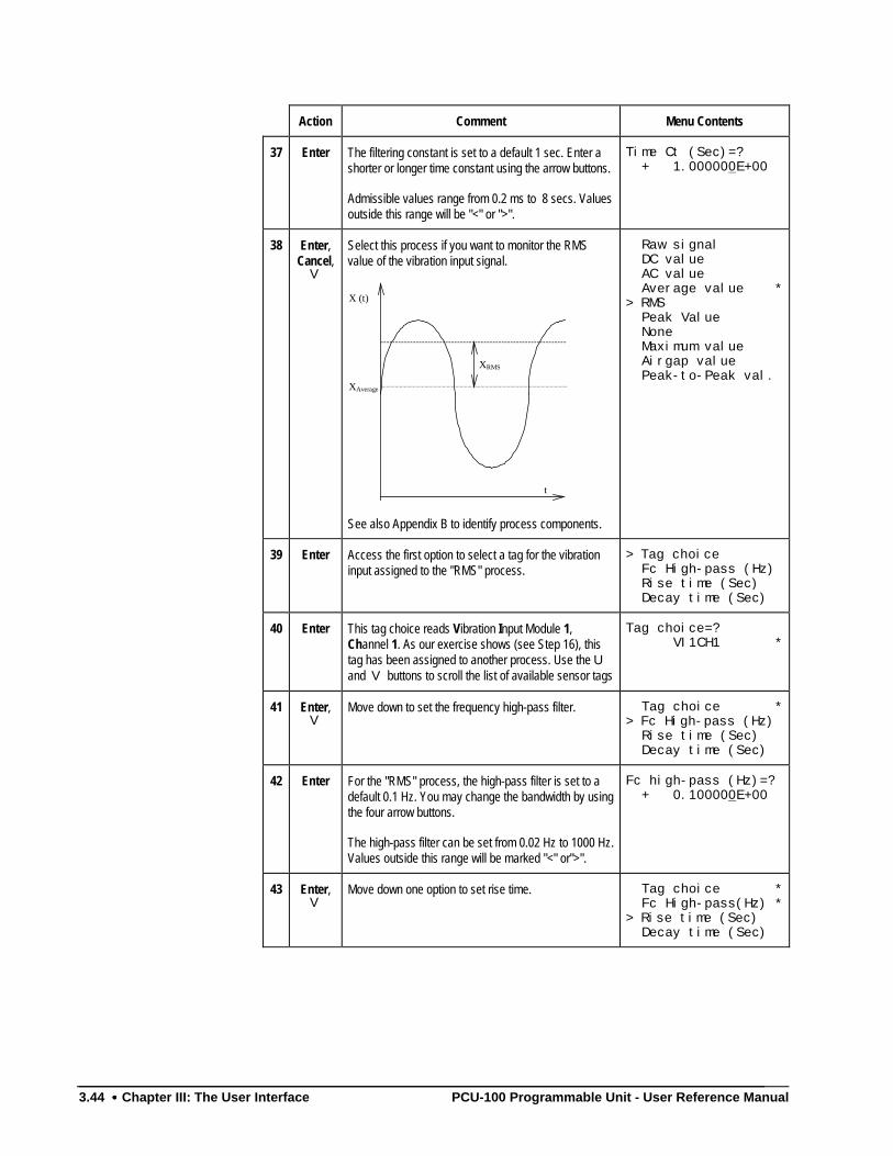
3.44 •••• Chapter III: The User Interface PCU-100 Programmable Unit - User Reference Manual
Action Comment Menu Contents
37 Enter The filtering constant is set to a default 1 sec. Enter ashorter or longer time constant using the arrow buttons.
Admissible values range from 0.2 ms to 8 secs. Valuesoutside this range will be "<" or ">".
Time Ct (Sec)=? + 1.000000E+00
38 Enter,Cancel,
V
Select this process if you want to monitor the RMSvalue of the vibration input signal.
XRMS
XAverage
t
X (t)
See also Appendix B to identify process components.
Raw signal DC value AC value Average value *
> RMS Peak Value None Maximum value Airgap value Peak-to-Peak val.
39 Enter Access the first option to select a tag for the vibrationinput assigned to the "RMS" process.
> Tag choice Fc High-pass (Hz) Rise time (Sec) Decay time (Sec)
40 Enter This tag choice reads Vibration Input Module 1,Channel 1. As our exercise shows (see Step 16), thistag has been assigned to another process. Use the Uand V buttons to scroll the list of available sensor tags
Tag choice=? VI1CH1 *
41 Enter,V
Move down to set the frequency high-pass filter. Tag choice *> Fc High-pass (Hz) Rise time (Sec)
Decay time (Sec)
42 Enter For the "RMS" process, the high-pass filter is set to adefault 0.1 Hz. You may change the bandwidth by usingthe four arrow buttons.
The high-pass filter can be set from 0.02 Hz to 1000 Hz.Values outside this range will be marked "<" or">".
Fc high-pass (Hz)=? + 0.100000E+00
43 Enter,V
Move down one option to set rise time. Tag choice * Fc High-pass(Hz) *
> Rise time (Sec) Decay time (Sec)
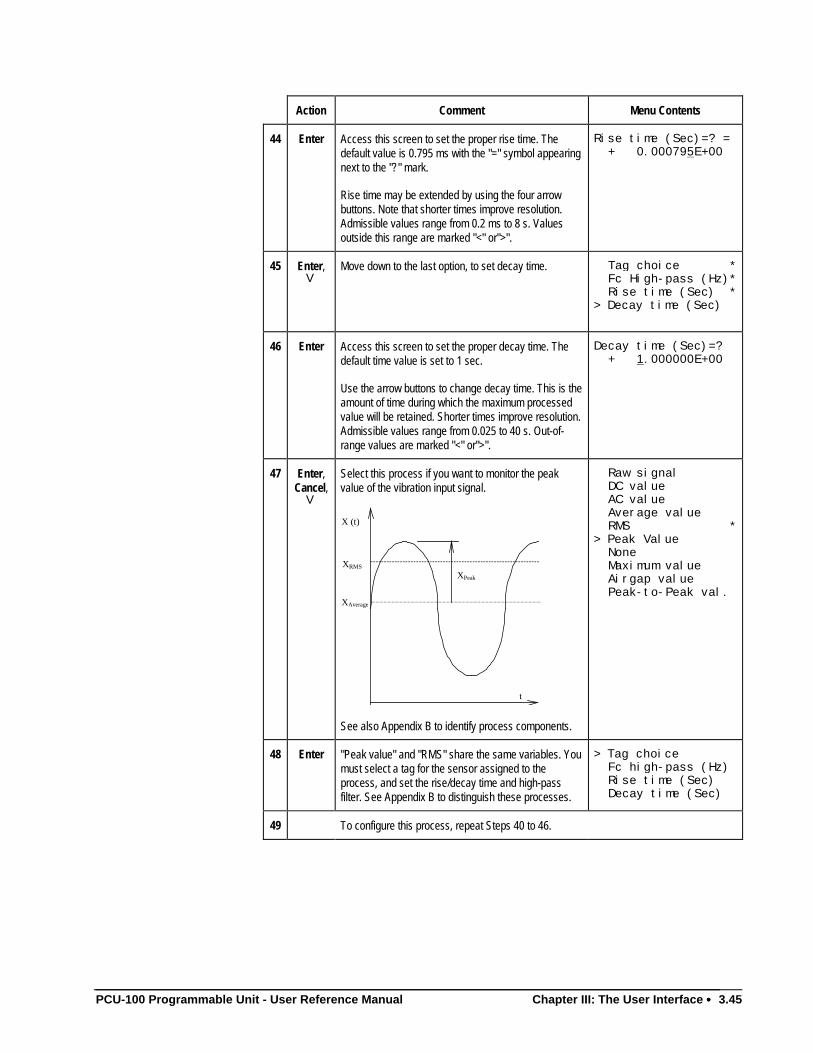
PCU-100 Programmable Unit - User Reference Manual Chapter III: The User Interface •••• 3.45
Action Comment Menu Contents
44 Enter Access this screen to set the proper rise time. Thedefault value is 0.795 ms with the "=" symbol appearingnext to the "?" mark.
Rise time may be extended by using the four arrowbuttons. Note that shorter times improve resolution.Admissible values range from 0.2 ms to 8 s. Valuesoutside this range are marked "<" or">".
Rise time (Sec)=? = + 0.000795E+00
45 Enter,V
Move down to the last option, to set decay time. Tag choice * Fc High-pass (Hz)* Rise time (Sec) *> Decay time (Sec)
46 Enter Access this screen to set the proper decay time. Thedefault time value is set to 1 sec.
Use the arrow buttons to change decay time. This is theamount of time during which the maximum processedvalue will be retained. Shorter times improve resolution.Admissible values range from 0.025 to 40 s. Out-of-range values are marked "<" or">".
Decay time (Sec)=? + 1.000000E+00
47 Enter,Cancel,
V
Select this process if you want to monitor the peakvalue of the vibration input signal.
XAverage
t
X (t)
XPeak
XRMS
See also Appendix B to identify process components.
Raw signal DC value AC value Average value RMS *> Peak Value None Maximum value Airgap value Peak-to-Peak val.
48 Enter "Peak value" and "RMS" share the same variables. Youmust select a tag for the sensor assigned to theprocess, and set the rise/decay time and high-passfilter. See Appendix B to distinguish these processes.
> Tag choice Fc high-pass (Hz) Rise time (Sec) Decay time (Sec)
49 To configure this process, repeat Steps 40 to 46.
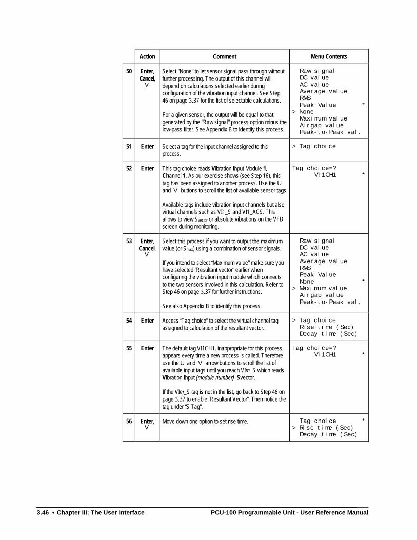
3.46 •••• Chapter III: The User Interface PCU-100 Programmable Unit - User Reference Manual
Action Comment Menu Contents
50 Enter,Cancel,
V
Select "None" to let sensor signal pass through withoutfurther processing. The output of this channel willdepend on calculations selected earlier duringconfiguration of the vibration input channel. See Step46 on page 3.37 for the list of selectable calculations.
For a given sensor, the output will be equal to thatgenerated by the "Raw signal" process option minus thelow-pass filter. See Appendix B to identify this process.
Raw signal DC value AC value Average value RMS Peak Value *
> None Maximum value Airgap value Peak-to-Peak val.
51 Enter Select a tag for the input channel assigned to thisprocess.
> Tag choice
52 Enter This tag choice reads Vibration Input Module 1,Channel 1. As our exercise shows (see Step 16), thistag has been assigned to another process. Use the Uand V buttons to scroll the list of available sensor tags
Available tags include vibration input channels but alsovirtual channels such as VI1_S and VI1_ACS. Thisallows to view Svector or absolute vibrations on the VFDscreen during monitoring.
Tag choice=? VI1CH1 *
53 Enter,Cancel,
V
Select this process if you want to output the maximumvalue (or Smax) using a combination of sensor signals.
If you intend to select “Maximum value” make sure youhave selected “Resultant vector” earlier whenconfiguring the vibration input module which connectsto the two sensors involved in this calculation. Refer toStep 46 on page 3.37 for further instructions.
See also Appendix B to identify this process.
Raw signal DC value AC value Average value RMS Peak Value None *
> Maximum value Airgap value Peak-to-Peak val.
54 Enter Access “Tag choice” to select the virtual channel tagassigned to calculation of the resultant vector.
> Tag choice Rise time (Sec) Decay time (Sec)
55 Enter The default tag VI1CH1, inappropriate for this process,appears every time a new process is called. Thereforeuse the U and V arrow buttons to scroll the list ofavailable input tags until you reach VIm_S which readsVibration Input (module number) Svector.
If the VIm_S tag is not in the list, go back to Step 46 onpage 3.37 to enable “Resultant Vector”. Then notice thetag under “S Tag”.
Tag choice=? VI1CH1 *
56 Enter,V
Move down one option to set rise time. Tag choice *> Rise time (Sec) Decay time (Sec)
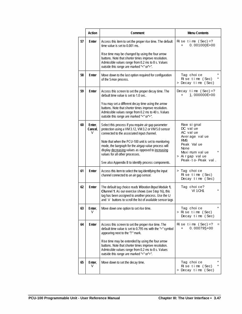
PCU-100 Programmable Unit - User Reference Manual Chapter III: The User Interface •••• 3.47
Action Comment Menu Contents
57 Enter Access this item to set the proper rise time. The defaulttime value is set to 0.001 ms.
Rise time may be changed by using the four arrowbuttons. Note that shorter times improve resolution.Admissible values range from 0.2 ms to 8 s. Valuesoutside this range are marked "<" or">".
Rise time (Sec)=? + 0.001000E+00
58 Enter Move down to the last option required for configurationof the Smax process.
Tag choice * Rise time (Sec) *> Decay time (Sec)
59 Enter Access this screen to set the proper decay time. Thedefault time value is set to 1.0 sec.
You may set a different decay time using the arrowbuttons. Note that shorter times improve resolution.Admissible values range from 0.2 ms to 40 s. Valuesoutside this range are marked "<" or">".
Decay time (Sec)=? + 1.000000E+00
60 Enter,Cancel,
V
Select this process if you require air gap parameterprotection using a VM 3.12, VM 3.2 or VM 5.0 sensorconnected to the associated input channel.
Note that when the PCU-100 unit is set to monitoringmode, the bargraph for the airgap value process willdisplay decreasing values as opposed to increasingvalues for all other processes.
See also Appendix B to identify process components.
Raw signal DC value AC value Average value RMS Peak Value None Maximum value *> Airgap value Peak-to-Peak val.
61 Enter Access this item to select the tag identifying the inputchannel connected to an air gap sensor.
> Tag choice Rise time (Sec) Decay time (Sec)
62 Enter The default tag choice reads Vibration Input Module 1,Channel 1. As our exercise shows (see Step 16), thistag has been assigned to another process. Use the Uand V buttons to scroll the list of available sensor tags
Tag choice? VI1CH1 *
63 Enter,V
Move down one option to set rise time. Tag choice *> Rise time (Sec) Decay time (Sec)
64 Enter Access this screen to set the proper rise time. Thedefault time value is set to 0.795 ms with the "=" symbolappearing next to the "?" mark.
Rise time may be extended by using the four arrowbuttons. Note that shorter times improve resolution.Admissible values range from 0.2 ms to 8 s. Valuesoutside this range are marked "<" or">".
Rise time (Sec)=? = + 0.000795+00
65 Enter,V
Move down to set the decay time. Tag choice * Rise time (Sec) *> Decay time (Sec)
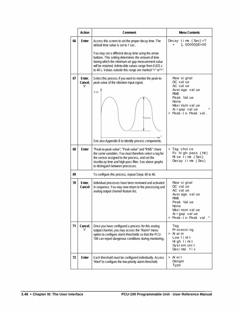
3.48 •••• Chapter III: The User Interface PCU-100 Programmable Unit - User Reference Manual
Action Comment Menu Contents
66 Enter Access this screen to set the proper decay time. Thedefault time value is set to 1 sec.
You may set a different decay time using the arrowbuttons. This setting determines the amount of timeduring which the minimum air gap measurement valuewill be retained. Admissible values range from 0.025 sto 40 s. Values outside this range are marked "<" or">".
Decay time (Sec)=? + 1.000000E+00
67 Enter,Cancel,
V
Select this process if you want to monitor the peak-to-peak value of the vibration input signal.
XPeak-Peak
t
X (t)
See also Appendix B to identify process components.
Raw signal DC value AC value Average value RMS Peak Value None Maximum value Airgap value *
> Peak-to-Peak val.
68 Enter "Peak-to-peak value", "Peak value" and "RMS" sharethe same variables. You must therefore select a tag forthe sensor assigned to the process, and set therise/decay time and high-pass filter. See above graphsto distinguish between processes.
> Tag choice Fc high-pass (Hz) Rise time (Sec) Decay time (Sec)
69 To configure this process, repeat Steps 40 to 46.
70 Enter,Cancel
Individual processes have been reviewed and activatedin sequence. You may now return to the processing andanalog output channel feature list.
Raw signal DC value AC value Average value RMS Peak Value None Maximum value Airgap value> Peak-to-Peak val.*
71 Cancel,V
Once you have configured a process for this analogoutput channel, you may access the "Alarm" menuoption to configure alarm thresholds so that the PCU-100 can report dangerous conditions during monitoring.
Tag Processing> Alarm Low limit High limit System unit Decimal fix
72 Enter Each threshold must be configured individually. Access“Alert” to configure the low priority alarm threshold.
> Alert Danger Type
PCU-100 Programmable Unit - User Reference Manual Chapter III: The User Interface •••• 3.49
Action Comment Menu Contents
73 Enter,V
Select "Enable" to take advantage of this functionality.A "*" will appear next to the selection the next time it isdisplayed.
Disable *> Enable
74 Enter This list runs down the variables involved in theconfiguration of the Alert alarm threshold.
> Tag Thresholds Hysteresis (%) Delay Latched
75 Enter Access this item to take note of the static tag for theAlert alarm threshold. You will refer to it later.
Note that tag "AO1CH1A1" is an extension of apreviously selected tag (see Step 12), namely:"AO1CH1". "AO1CH1A1 reads: Analog Output Module1, Channel 1, Alert 1.
Tag= A01CH1A1
76 Enter,V
Move to the next option required to configure the Alertalarm threshold.
Tag> Thresholds Hysteresis (%) Delay Latched
77 Enter,V
Access "Threshold DI=1" to set a single Alert leveltriggering value. Access both thresholds if your wish touse the Threshold set selection logic input featureconfigured in Step 5 on page 3.63.
This dual threshold adds flexibility to your monitoringenvironment by allowing toggling between two sets ofAlert and Danger thresholds so as to safeguardagainst irrelevant alarms.
> Threshold DI=1 * Threshold DI=0 *
78 Enter A default value of 1900 µm has been set as thetriggering value for the Alert threshold. It is a suitablethreshold for a sensor range of 500 to 2500 µm. Youmay change this value using the four arrow buttons.
Threshold DI=1=? +1.900000E+03
79 Enter,V
Move down to ”Threshold DI=0” if your wish to use theThreshold set selection feature which enables remoteswitching between two Alert threshold settings.
Threshold DI=1 *> Threshold DI=0 *
80 Enter The default value of 1900 µm has already beenassigned as the triggering value for DI=1 which is thereference Alert threshold. Set a higher or lower settingdepending on whether you wish to extend or reduce thearea of the measuring range with no alarm reporting.
Note that DI=0 Alert threshold pairs with DI=0 Dangerthreshold which will be configured a few steps down.
Threshold DI=0=? +1.900000E+03
81 Enter,Cancel,
V
Move down to set the Hysteresis value for this alarmthreshold.
Tag Thresholds> Hysteresis (%) Delay Latched
3.50 •••• Chapter III: The User Interface PCU-100 Programmable Unit - User Reference Manual
Action Comment Menu Contents
82 Enter "Hysteresis" represents a percentage of the measuringrange below the Alert threshold value. In practice, anAlert condition will be canceled only if and whenreadings fall below the Hysteresis value (%). Thissetting is used to blank out noise in the sensor signaland is valid for both Alert thresholds.
Hysteresis is set to a default 5%. You may change thissetting using the four arrow buttons. Admissible valuesrange from 0% to 20%. Values outside this range arelabeled "<" or">" next to the "?" mark.
Hysteresis (%)=? + 5.000000E+00
83 Enter,V
Move down to set the time delay allowed beforetriggering of the Alert alarm.
Tag Thresholds Hysteresis (%)> Delay Latched
84 Enter Select “Time delay” to determine the amount of timeduring which reading exceeds alarm threshold beforean alarm can be reported. This is the default setting forall processes except for “Airgap value”.
> Time delay (Sec)* Number of Rev.
85 Enter "Time delay" refers to the amount of time (in seconds)allowed before an alarm is triggered once readingshave reached and remained above the Alert threshold.
The default 1 second may be changed using the arrowbuttons. Admissible values range from 0 to 300seconds. Out-of-range values are marked "<" or">".
Time delay (Sec)=? + 1.000000E+00
86 Enter,V
If you set “Airgap value” earlier as the process for thisoutput channel, select “Number of Rev.”.
Time delay (Sec)*> Number of Rev.
87 Enter The number of revs sets the number of consecutivemachine rotations during which air gap values mustremain below the Alert threshold level before an Alertlevel alarm is triggered. The PCU-100 detects alarmvalues at a minimum rate of 0.5 rotations/sec and amaximum of 20 rotations/sec. Furthermore, if an alarmvalue is recorded half-way during a rotation, it will bemaintained for the entire duration of the rotation.
The default is set to 1 rev. per second. However, thisvalue may be changed using the arrow buttons.Thenumber of revolutions set for Alert must not exceed thenumber of revolutions set for Danger.
Number of Rev.=? + 1.000000E+00
88 Enter,Cancel,
V
Move down to the last option required for configurationof the Alert alarm threshold.
Tag Thresholds Hysteresis (%) Delay> Latched
PCU-100 Programmable Unit - User Reference Manual Chapter III: The User Interface •••• 3.51
Action Comment Menu Contents
89 Enter Alarms are "latched" by default as indicated by a "*"next to the selection. Leave the "Latch" feature enabledif you want alarm signals to lock on and remain activeuntil they are manually acknowledged.
Select "Disable" if you want alarms to trigger on and offas measurement values change.
> Disable Enable *
90 Enter,Cancel(twice),
V
Move down to configure the high priority "Danger"threshold.
Alert> Danger Type
91 Enter,V
Select "Enable" to take advantage of this functionality.A "*" will appear next to the selection the next time it isdisplayed.
Disable *> Enable
92 Enter Once again, this list runs down the variables requiredfor configuration of the Danger alarm threshold.
> Tag Thresholds Hysteresis (%) Delay Latched
93 Enter Access this item to take note of the static tag for theDanger alarm threshold. You will refer to it later.
Notice that the system has moved up to the next logicalchoice for the Danger alarm threshold. "AO1CH1D1reads: Analog Output Module 1, Channel 1, Danger 1.
Tag= A01CH1D1
94 Enter,V
Move to the next option required for configuration of theDanger alarm threshold.
Tag> Thresholds Hysteresis (%) Delay Latched
95 Enter Access "Threshold DI=1" to set a single Danger leveltriggering value. Access both thresholds if your wish touse the Threshold set selection logic input featureconfigured in Step 5 on page 3.63.
This dual threshold adds flexibility to your monitoringenvironment by allowing toggling between two sets ofAlert Danger thresholds so as to safeguard againstirrelevant alarms.
> Threshold DI=1 * Threshold DI=0 *
96 Enter A default value of 2200 µm has been set as thetriggering value for the Danger threshold. It is a suitablethreshold for a sensor range of 500 to 2500 µm.However, you may change this value using the fourarrow buttons.
Threshold DI=1=? +2.200000E+03
97 Enter,V
Move down to ”Threshold DI=0” if your wish to use theThreshold set selection feature which enables remoteswitching between two Danger threshold settings.
Threshold DI=1 *> Threshold DI=0 *
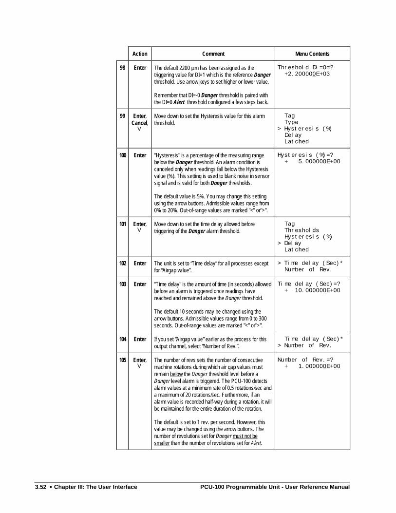
3.52 •••• Chapter III: The User Interface PCU-100 Programmable Unit - User Reference Manual
Action Comment Menu Contents
98 Enter The default 2200 µm has been assigned as thetriggering value for DI=1 which is the reference Dangerthreshold. Use arrow keys to set higher or lower value.
Remember that DI=-0 Danger threshold is paired withthe DI=0 Alert threshold configured a few steps back.
Threshold DI=0=? +2.200000E+03
99 Enter,Cancel,
V
Move down to set the Hysteresis value for this alarmthreshold.
Tag Type> Hysteresis (%) Delay Latched
100 Enter "Hysteresis" is a percentage of the measuring rangebelow the Danger threshold. An alarm condition iscanceled only when readings fall below the Hysteresisvalue (%). This setting is used to blank noise in sensorsignal and is valid for both Danger thresholds.
The default value is 5%. You may change this settingusing the arrow buttons. Admissible values range from0% to 20%. Out-of-range values are marked "<" or">".
Hysteresis (%)=? + 5.000000E+00
101 Enter,V
Move down to set the time delay allowed beforetriggering of the Danger alarm threshold.
Tag Thresholds Hysteresis (%)> Delay Latched
102 Enter The unit is set to “Time delay” for all processes exceptfor “Airgap value”.
> Time delay (Sec)* Number of Rev.
103 Enter "Time delay" is the amount of time (in seconds) allowedbefore an alarm is triggered once readings havereached and remained above the Danger threshold.
The default 10 seconds may be changed using thearrow buttons. Admissible values range from 0 to 300seconds. Out-of-range values are marked "<" or">".
Time delay (Sec)=? + 10.000000E+00
104 Enter If you set “Airgap value” earlier as the process for thisoutput channel, select “Number of Rev.”.
Time delay (Sec)*> Number of Rev.
105 Enter,V
The number of revs sets the number of consecutivemachine rotations during which air gap values mustremain below the Danger threshold level before aDanger level alarm is triggered. The PCU-100 detectsalarm values at a minimum rate of 0.5 rotations/sec anda maximum of 20 rotations/sec. Furthermore, if analarm value is recorded half-way during a rotation, it willbe maintained for the entire duration of the rotation.
The default is set to 1 rev. per second. However, thisvalue may be changed using the arrow buttons. Thenumber of revolutions set for Danger must not besmaller than the number of revolutions set for Alert.
Number of Rev.=? + 1.000000E+00
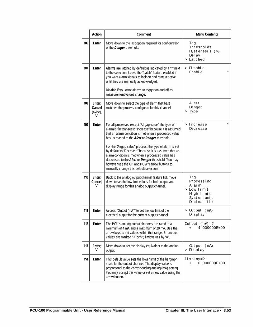
PCU-100 Programmable Unit - User Reference Manual Chapter III: The User Interface •••• 3.53
Action Comment Menu Contents
106 Enter Move down to the last option required for configurationof the Danger threshold.
Tag Thresholds Hysteresis (%) Delay> Latched
107 Enter Alarms are latched by default as indicated by a "*" nextto the selection. Leave the "Latch" feature enabled ifyou want alarm signals to lock on and remain activeuntil they are manually acknowledged.
Disable if you want alarms to trigger on and off asmeasurement values change.
> Disable Enable *
108 Enter,Cancel(twice),
V
Move down to select the type of alarm that bestmatches the process configured for this channel.
Alert Danger> Type
109 Enter For all processes except “Airgap value”, the type ofalarm is factory-set to “Increase” because it is assumedthat an alarm condition is met when a processed valuehas increased to the Alert or Danger threshold.
For the “Airgap value” process, the type of alarm is setby default to “Decrease” because it is assumed that analarm condition is met when a processed value hasdecreased to the Alert or Danger threshold. You mayhowever use the UP and DOWN arrow buttons tomanually change this default selection.
> Increase * Decrease
110 Enter,Cancel,
V
Back to the analog output channel feature list, movedown to set the low limit values for both output anddisplay range for this analog output channel.
Tag Processing Alarm> Low limit High limit System unit Decimal fix
111 Enter Access "Output (mA)" to set the low limit of theelectrical output for the current output channel.
> Output (mA) Display
112 Enter The PCU's analog output channels are rated at aminimum of 4 mA and a maximum of 20 mA. Use thearrow keys to set values within that range. Erroneousvalues are marked "<" or">", limit values by "=".
Output (mA)=? = + 4.000000E+00
113 Enter,V
Move down to set the display equivalent to the analogoutput.
Output (mA)> Display
114 Enter This default value sets the lower limit of the bargraphscale for the output channel. The display value isproportional to the corresponding analog (mA) setting.You may accept this value or set a new value using thearrow buttons.
Display=? + 0.000000E+00
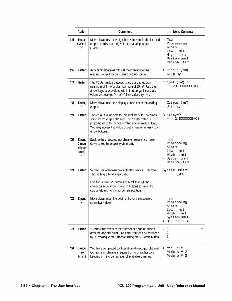
3.54 •••• Chapter III: The User Interface PCU-100 Programmable Unit - User Reference Manual
Action Comment Menu Contents
115 Enter,Cancel,
V
Move down to set the high limit values for both electricaloutput and display ranges for this analog outputchannel.
Tag Processing Alarm Low limit> High limit System unit Decimal fix
116 Enter Access "Output (mA)" to set the high limit of theelectrical output for the current output channel.
> Output (mA) Display
117 Enter The PCU's analog output channels are rated at aminimum of 4 mA and a maximum of 20 mA. Use thearrow keys to set values within that range. Erroneousvalues are marked "<" or">", limit values by "=".
Output (mA)=? = + 20.000000E+00
118 Enter,V
Move down to set the display equivalent to the analogoutput.
Output (mA)> Display
119 Enter This default value sets the higher limit of the bargraphscale for the output channel. The display value isproportional to the corresponding analog (mA) setting.You may accept this value or set a new value using thearrow buttons.
Display=? + 2.500000E+03
120 Enter,Cancel(threetimes),
V
Back to the analog output channel feature list, movedown to set the proper system unit.
Tag Processing Alarm Low limit High limit> System unit Decimal fix
121 Enter Set the unit of measurement for the process selected.This setting is for display only.
Use the U and V buttons to scroll through thecharacter set and the T and S buttons to move thecursor left and right of its current position.
System unit=? µm
122 Enter,V
Move down to set the decimal fix for the displayednumerical values.
Tag Processing Alarm Low limit High limit System unit> Decimal fix
123 Enter "Decimal fix" refers to the number of digits displayedafter the decimal point. The default "0" can be extendedto "3" moving to the selection using the V arrow button.
> 0 * 1 2 3
124 Cancel(six
times)
You have completed configuration of an output channel.Configure all channels required by your applicationskeeping in mind the number of available channels.
> Module # 1 Module # 2 Module # 3
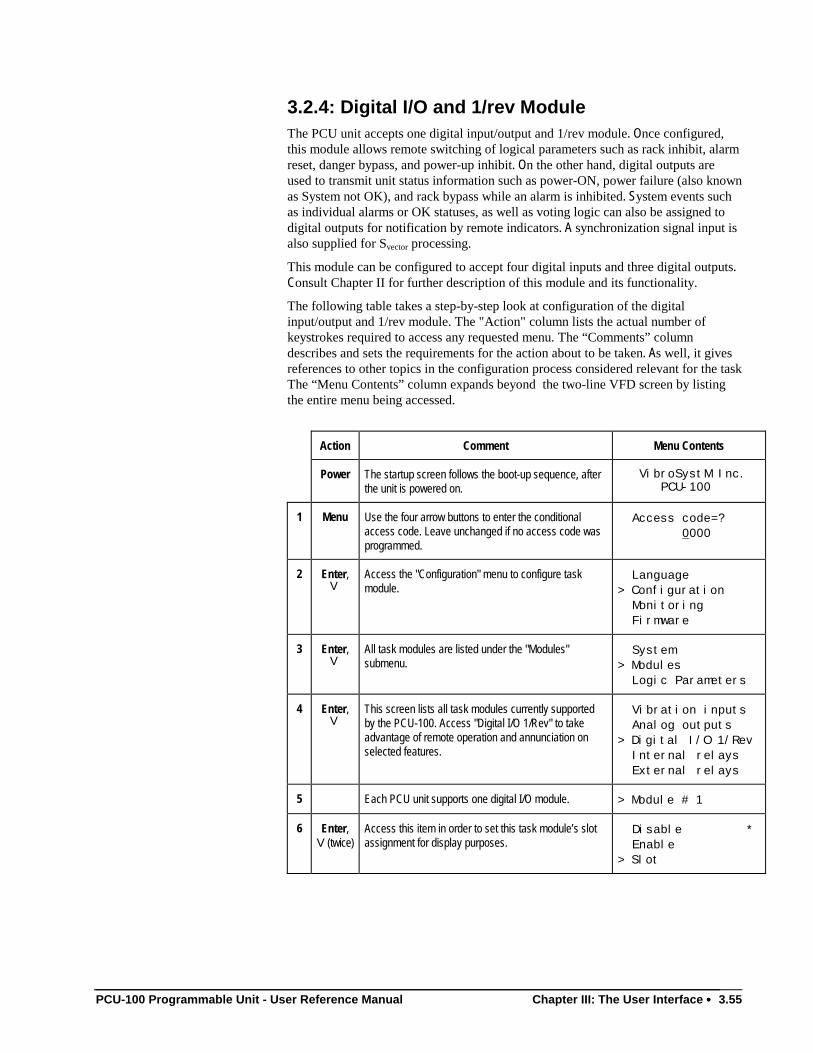
PCU-100 Programmable Unit - User Reference Manual Chapter III: The User Interface •••• 3.55
3.2.4: Digital I/O and 1/rev ModuleThe PCU unit accepts one digital input/output and 1/rev module. Once configured,this module allows remote switching of logical parameters such as rack inhibit, alarmreset, danger bypass, and power-up inhibit. On the other hand, digital outputs areused to transmit unit status information such as power-ON, power failure (also knownas System not OK), and rack bypass while an alarm is inhibited. System events suchas individual alarms or OK statuses, as well as voting logic can also be assigned todigital outputs for notification by remote indicators. A synchronization signal input isalso supplied for Svector processing.
This module can be configured to accept four digital inputs and three digital outputs.Consult Chapter II for further description of this module and its functionality.
The following table takes a step-by-step look at configuration of the digitalinput/output and 1/rev module. The "Action" column lists the actual number ofkeystrokes required to access any requested menu. The “Comments” columndescribes and sets the requirements for the action about to be taken. As well, it givesreferences to other topics in the configuration process considered relevant for the taskThe “Menu Contents” column expands beyond the two-line VFD screen by listingthe entire menu being accessed.
Action Comment Menu Contents
Power The startup screen follows the boot-up sequence, afterthe unit is powered on.
VibroSystM Inc. PCU-100
1 Menu Use the four arrow buttons to enter the conditionalaccess code. Leave unchanged if no access code wasprogrammed.
Access code=? 0000
2 Enter,V
Access the "Configuration" menu to configure taskmodule.
Language> Configuration Monitoring Firmware
3 Enter,V
All task modules are listed under the "Modules"submenu.
System> Modules Logic Parameters
4 Enter,V
This screen lists all task modules currently supportedby the PCU-100. Access "Digital I/O 1/Rev" to takeadvantage of remote operation and annunciation onselected features.
Vibration inputs Analog outputs> Digital I/O 1/Rev Internal relays External relays
5 Each PCU unit supports one digital I/O module. > Module # 1
6 Enter,V(twice)
Access this item in order to set this task module’s slotassignment for display purposes.
Disable * Enable> Slot
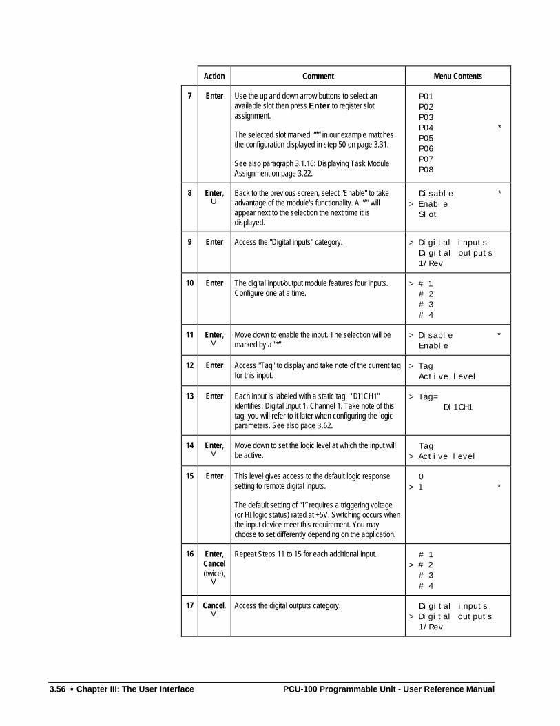
3.56 •••• Chapter III: The User Interface PCU-100 Programmable Unit - User Reference Manual
Action Comment Menu Contents
7 Enter Use the up and down arrow buttons to select anavailable slot then press Enter to register slotassignment.
The selected slot marked “*” in our example matchesthe configuration displayed in step 50 on page 3.31.
See also paragraph 3.1.16: Displaying Task ModuleAssignment on page 3.22.
P01 P02 P03 P04 * P05 P06 P07 P08
8 Enter,U
Back to the previous screen, select "Enable" to takeadvantage of the module's functionality. A "*" willappear next to the selection the next time it isdisplayed.
Disable *> Enable Slot
9 Enter Access the "Digital inputs" category. > Digital inputs Digital outputs 1/Rev
10 Enter The digital input/output module features four inputs.Configure one at a time.
> # 1 # 2 # 3 # 4
11 Enter,V
Move down to enable the input. The selection will bemarked by a "*".
> Disable * Enable
12 Enter Access "Tag" to display and take note of the current tagfor this input.
> Tag Active level
13 Enter Each input is labeled with a static tag. "DI1CH1"identifies: Digital Input 1, Channel 1. Take note of thistag, you will refer to it later when configuring the logicparameters. See also page 3.62.
> Tag= DI1CH1
14 Enter,V
Move down to set the logic level at which the input willbe active.
Tag> Active level
15 Enter This level gives access to the default logic responsesetting to remote digital inputs.
The default setting of “1” requires a triggering voltage(or HI logic status) rated at +5V. Switching occurs whenthe input device meet this requirement. You maychoose to set differently depending on the application.
0> 1 *
16 Enter,Cancel(twice),
V
Repeat Steps 11 to 15 for each additional input. # 1> # 2 # 3 # 4
17 Cancel,V
Access the digital outputs category. Digital inputs> Digital outputs 1/Rev
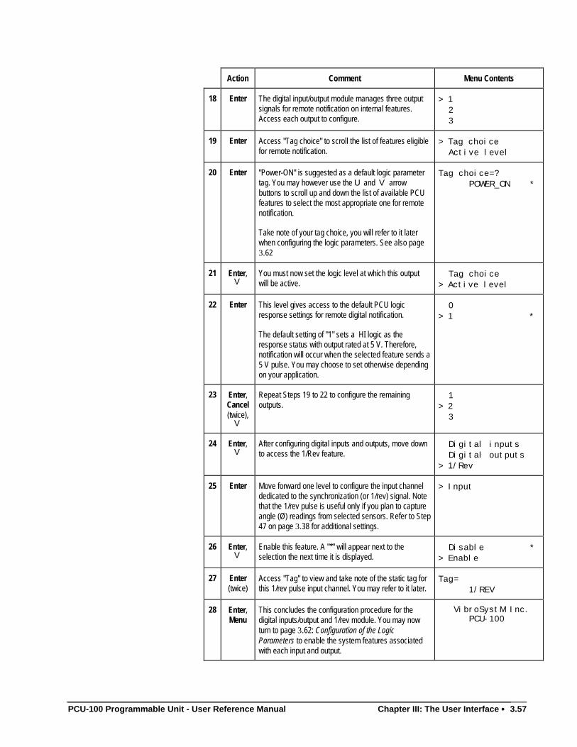
PCU-100 Programmable Unit - User Reference Manual Chapter III: The User Interface •••• 3.57
Action Comment Menu Contents
18 Enter The digital input/output module manages three outputsignals for remote notification on internal features.Access each output to configure.
> 1 2 3
19 Enter Access "Tag choice" to scroll the list of features eligiblefor remote notification.
> Tag choice Active level
20 Enter "Power-ON" is suggested as a default logic parametertag. You may however use the U and V arrowbuttons to scroll up and down the list of available PCUfeatures to select the most appropriate one for remotenotification.
Take note of your tag choice, you will refer to it laterwhen configuring the logic parameters. See also page3.62
Tag choice=? POWER_ON *
21 Enter,V
You must now set the logic level at which this outputwill be active.
Tag choice> Active level
22 Enter This level gives access to the default PCU logicresponse settings for remote digital notification.
The default setting of "1" sets a HI logic as theresponse status with output rated at 5 V. Therefore,notification will occur when the selected feature sends a5 V pulse. You may choose to set otherwise dependingon your application.
0> 1 *
23 Enter,Cancel(twice),
V
Repeat Steps 19 to 22 to configure the remainingoutputs.
1> 2 3
24 Enter,V
After configuring digital inputs and outputs, move downto access the 1/Rev feature.
Digital inputs Digital outputs> 1/Rev
25 Enter Move forward one level to configure the input channeldedicated to the synchronization (or 1/rev) signal. Notethat the 1/rev pulse is useful only if you plan to captureangle (Ø) readings from selected sensors. Refer to Step47 on page 3.38 for additional settings.
> Input
26 Enter,V
Enable this feature. A "*" will appear next to theselection the next time it is displayed.
Disable *> Enable
27 Enter(twice)
Access "Tag" to view and take note of the static tag forthis 1/rev pulse input channel. You may refer to it later.
Tag= 1/REV
28 Enter,Menu
This concludes the configuration procedure for thedigital inputs/output and 1/rev module. You may nowturn to page 3.62: Configuration of the LogicParameters to enable the system features associatedwith each input and output.
VibroSystM Inc. PCU-100
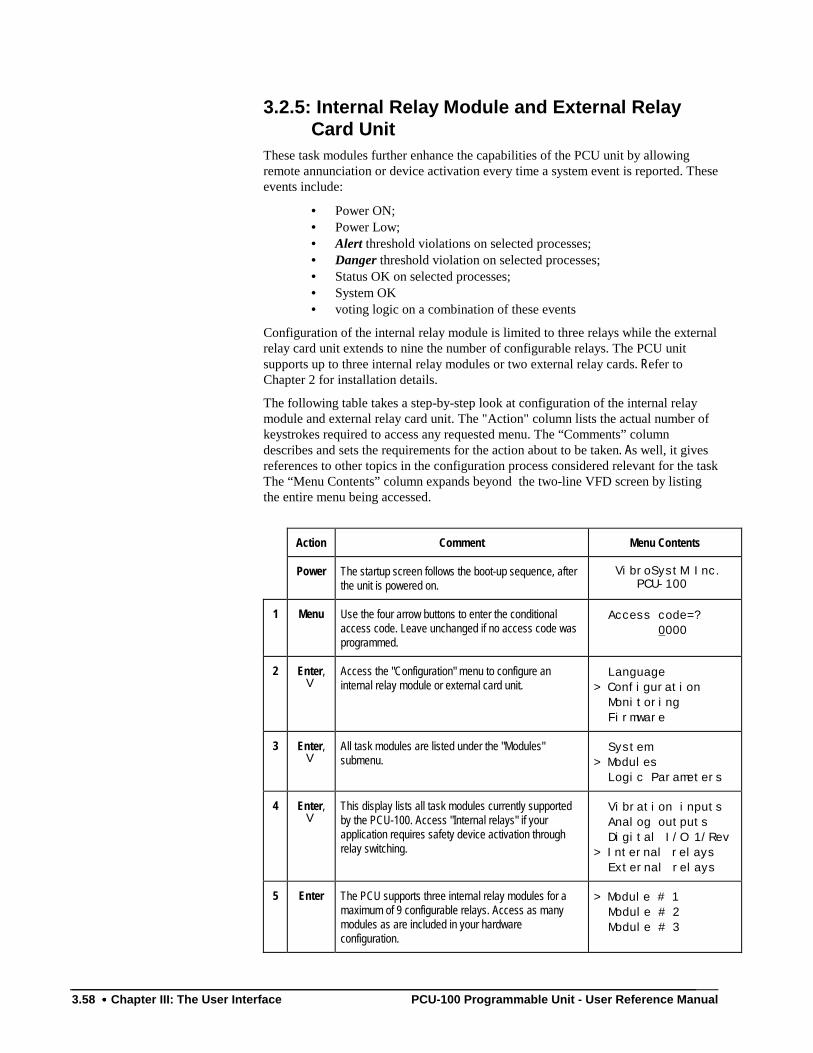
3.58 •••• Chapter III: The User Interface PCU-100 Programmable Unit - User Reference Manual
3.2.5: Internal Relay Module and External RelayCard Unit
These task modules further enhance the capabilities of the PCU unit by allowingremote annunciation or device activation every time a system event is reported. Theseevents include:
• Power ON;• Power Low;• Alert threshold violations on selected processes;• Danger threshold violation on selected processes;• Status OK on selected processes;• System OK• voting logic on a combination of these events
Configuration of the internal relay module is limited to three relays while the externalrelay card unit extends to nine the number of configurable relays. The PCU unitsupports up to three internal relay modules or two external relay cards. Refer toChapter 2 for installation details.
The following table takes a step-by-step look at configuration of the internal relaymodule and external relay card unit. The "Action" column lists the actual number ofkeystrokes required to access any requested menu. The “Comments” columndescribes and sets the requirements for the action about to be taken. As well, it givesreferences to other topics in the configuration process considered relevant for the taskThe “Menu Contents” column expands beyond the two-line VFD screen by listingthe entire menu being accessed.
Action Comment Menu Contents
Power The startup screen follows the boot-up sequence, afterthe unit is powered on.
VibroSystM Inc. PCU-100
1 Menu Use the four arrow buttons to enter the conditionalaccess code. Leave unchanged if no access code wasprogrammed.
Access code=? 0000
2 Enter,V
Access the "Configuration" menu to configure aninternal relay module or external card unit.
Language> Configuration Monitoring Firmware
3 Enter,V
All task modules are listed under the "Modules"submenu.
System> Modules Logic Parameters
4 Enter,V
This display lists all task modules currently supportedby the PCU-100. Access "Internal relays" if yourapplication requires safety device activation throughrelay switching.
Vibration inputs Analog outputs Digital I/O 1/Rev> Internal relays External relays
5 Enter The PCU supports three internal relay modules for amaximum of 9 configurable relays. Access as manymodules as are included in your hardwareconfiguration.
> Module # 1 Module # 2 Module # 3
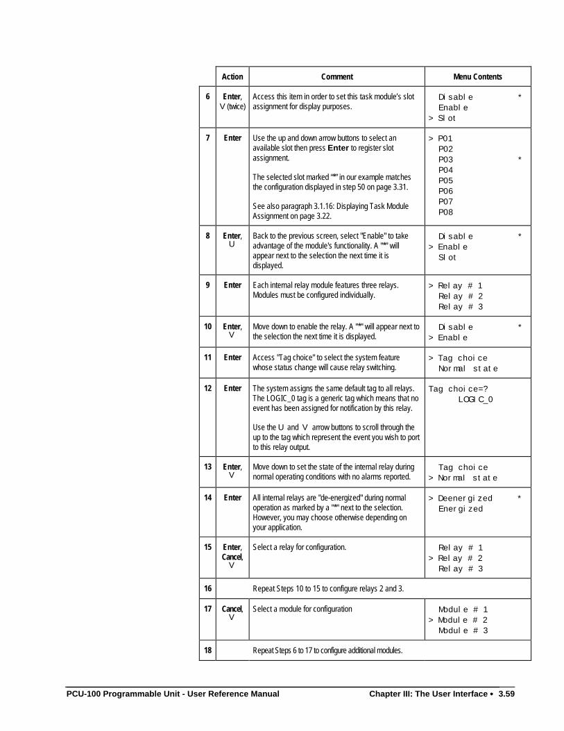
PCU-100 Programmable Unit - User Reference Manual Chapter III: The User Interface •••• 3.59
Action Comment Menu Contents
6 Enter,V(twice)
Access this item in order to set this task module’s slotassignment for display purposes.
Disable * Enable> Slot
7 Enter Use the up and down arrow buttons to select anavailable slot then press Enter to register slotassignment.
The selected slot marked “*” in our example matchesthe configuration displayed in step 50 on page 3.31.
See also paragraph 3.1.16: Displaying Task ModuleAssignment on page 3.22.
> P01 P02 P03 * P04 P05 P06 P07 P08
8 Enter,U
Back to the previous screen, select "Enable" to takeadvantage of the module's functionality. A "*" willappear next to the selection the next time it isdisplayed.
Disable *> Enable Slot
9 Enter Each internal relay module features three relays.Modules must be configured individually.
> Relay # 1 Relay # 2 Relay # 3
10 Enter,V
Move down to enable the relay. A "*" will appear next tothe selection the next time it is displayed.
Disable *> Enable
11 Enter Access "Tag choice" to select the system featurewhose status change will cause relay switching.
> Tag choice Normal state
12 Enter The system assigns the same default tag to all relays.The LOGIC_0 tag is a generic tag which means that noevent has been assigned for notification by this relay.
Use the U and V arrow buttons to scroll through theup to the tag which represent the event you wish to portto this relay output.
Tag choice=? LOGIC_0
13 Enter,V
Move down to set the state of the internal relay duringnormal operating conditions with no alarms reported.
Tag choice> Normal state
14 Enter All internal relays are "de-energized" during normaloperation as marked by a "*" next to the selection.However, you may choose otherwise depending onyour application.
> Deenergized * Energized
15 Enter,Cancel,
V
Select a relay for configuration. Relay # 1> Relay # 2 Relay # 3
16 Repeat Steps 10 to 15 to configure relays 2 and 3.
17 Cancel,V
Select a module for configuration Module # 1> Module # 2 Module # 3
18 Repeat Steps 6 to 17 to configure additional modules.
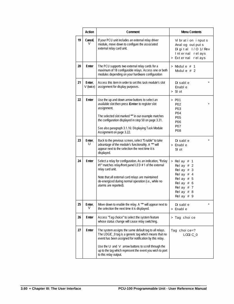
3.60 •••• Chapter III: The User Interface PCU-100 Programmable Unit - User Reference Manual
Action Comment Menu Contents
19 Cancel,V
If your PCU unit includes an external relay drivermodule, move down to configure the associatedexternal relay card unit.
Vibration inputs Analog outputs Digital I/O 1/Rev Internal relays> External relays
20 Enter The PCU supports two external relay cards for amaximum of 18 configurable relays. Access one or bothmodules depending on your hardware configuration
> Module # 1 Module # 2
21 Enter,V(twice)
Access this item in order to set this task module’s slotassignment for display purposes.
Disable * Enable> Slot
22 Enter Use the up and down arrow buttons to select anavailable slot then press Enter to register slotassignment.
The selected slot marked “*” in our example matchesthe configuration displayed in step 50 on page 3.31.
See also paragraph 3.1.16: Displaying Task ModuleAssignment on page 3.22.
> P01 P02 * P03 P04 P05 P06 P07 P08
23 Enter,U
Back to the previous screen, select "Enable" to takeadvantage of the module's functionality. A "*" willappear next to the selection the next time it isdisplayed.
Disable *> Enable Slot
24 Enter Select a relay for configuration. As an indication, "Relay#1" matches relay/front panel LED # 1 of the externalrelay card unit.
Note that all external card relays are maintainedde-energized during normal operation (i.e., while noalarms are reported).
> Relay # 1 Relay # 2 Relay # 3 Relay # 4 Relay # 5 Relay # 6 Relay # 7 Relay # 8 Relay # 9
25 Enter,V
Move down to enable the relay. A "*" will appear next tothe selection the next time it is displayed.
Disable *> Enable
26 Enter Access "Tag choice" to select the system featurewhose status change will cause relay switching.
> Tag choice
27 Enter The system assigns the same default tag to all relays.The LOGIC_0 tag is a generic tag which means that noevent has been assigned for notification by this relay.
Use the U and V arrow buttons to scroll through theup to the tag which represent the event you wish to portto this relay output.
Tag choice=? LOGIC_0
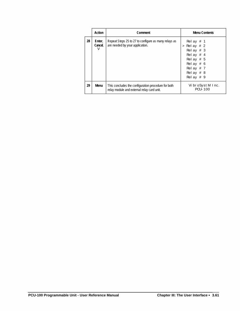
PCU-100 Programmable Unit - User Reference Manual Chapter III: The User Interface •••• 3.61
Action Comment Menu Contents
28 Enter,Cancel,
V
Repeat Steps 25 to 27 to configure as many relays asare needed by your application.
Relay # 1> Relay # 2 Relay # 3 Relay # 4 Relay # 5 Relay # 6 Relay # 7 Relay # 8 Relay # 9
29 Menu This concludes the configuration procedure for bothrelay module and external relay card unit.
VibroSystM Inc. PCU-100
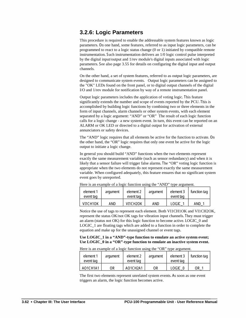
3.62 •••• Chapter III: The User Interface PCU-100 Programmable Unit - User Reference Manual
3.2.6: Logic ParametersThis procedure is required to enable the addressable system features known as logicparameters. On one hand, some features, referred to as input logic parameters, can beprogrammed to react to a logic status change (0 or 1) initiated by compatible remoteinstrumentation. Such instrumentation delivers an 1/0 logic control pulse interpretedby the digital input/output and 1/rev module's digital inputs associated with logicparameters. See also page 3.55 for details on configuring the digital input and outputchannels.
On the other hand, a set of system features, referred to as output logic parameters, aredesigned to communicate system events. Output logic parameters can be assigned tothe "OK" LEDs found on the front panel, or to digital output channels of the digitalI/O and 1/rev module for notification by way of a remote instrumentation panel.
Output logic parameters includes the application of voting logic. This featuresignificantly extends the number and scope of events reported by the PCU. This isaccomplished by building logic functions by combining two or three elements in theform of input channels, alarm channels or other system events, with each elementseparated by a logic argument: “AND” or “OR” The result of each logic functioncalls for a logic change - a new system event. In turn, this event can be reported on anALARM or OK LED or directed to a digital output for activation of externalannunciators or safety devices.
The “AND” logic requires that all elements be active for the function to activate. Onthe other hand, the “OR” logic requires that only one event be active for the logicoutput to initiate a logic change.
In general you should build “AND” functions when the two elements representexactly the same measurement variable (such as sensor redundancy) and when it islikely that a sensor failure will trigger false alarms. The “OR” voting logic function isappropriate when the two elements do not represent exactly the same measurementvariable. When configured adequately, this feature ensures that no significant systemevent goes by unreported.
Here is an example of a logic function using the “AND” type argument.
element 1event tag
argument element 2event tag
argument element 3event tag
function tag
VI1CH1OK AND VI1CH2OK AND LOGIC_1 AND_1
Notice the use of tags to represent each element. Both VI1CH1OK and VI1CH2OK,represent the status OK/not OK tags for vibration input channels. They must triggeran alarm (status not OK) for this logic function to become active. LOGIC_0 andLOGIC_1 are floating tags which are added to a function in order to complete theequation and make up for the unassigned channel or event tags.
Use LOGIC_1 in a “AND”-type function to emulate an active system event;Use LOGIC_0 in a “OR”-type function to emulate an inactive system event.
Here is an example of a logic function using the “OR” type argument.
element 1event tag
argument element 2event tag
argument element 3event tag
function tag
AO1CH1A1 OR AO1CH2A1 OR LOGIC_0 OR_1
The first two elements represent unrelated system events. As soon as one eventtriggers an alarm, the logic function becomes active.
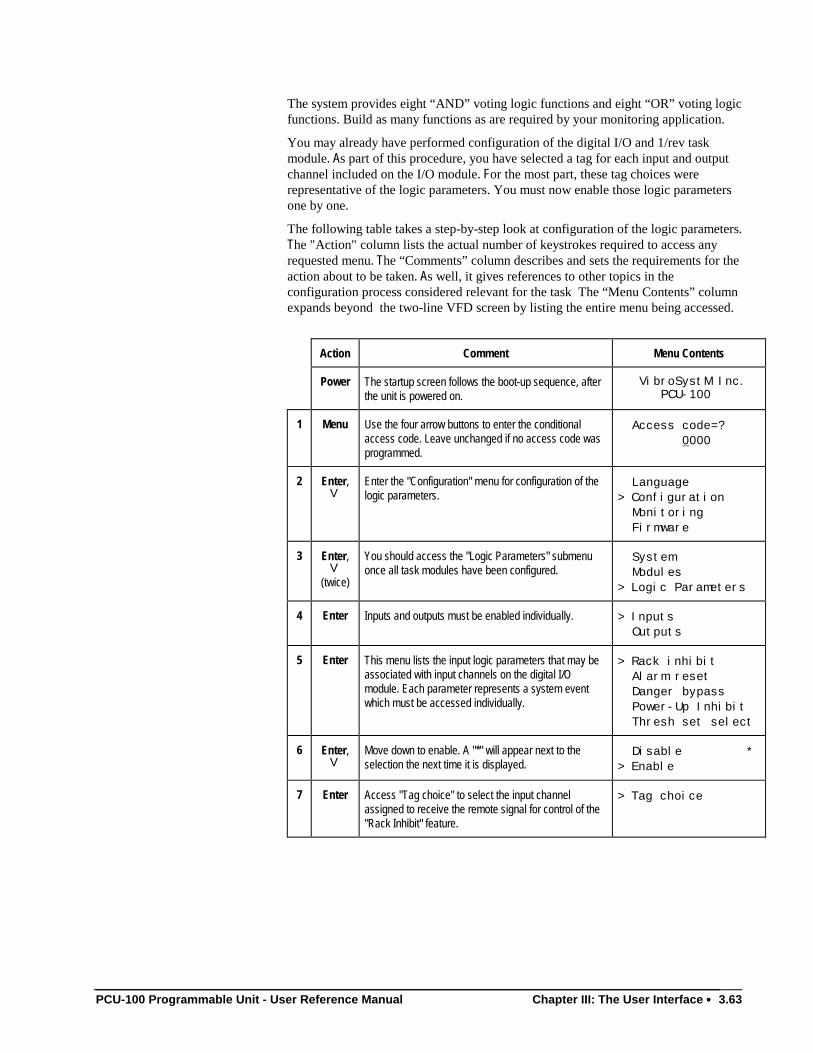
PCU-100 Programmable Unit - User Reference Manual Chapter III: The User Interface •••• 3.63
The system provides eight “AND” voting logic functions and eight “OR” voting logicfunctions. Build as many functions as are required by your monitoring application.
You may already have performed configuration of the digital I/O and 1/rev taskmodule. As part of this procedure, you have selected a tag for each input and outputchannel included on the I/O module. For the most part, these tag choices wererepresentative of the logic parameters. You must now enable those logic parametersone by one.
The following table takes a step-by-step look at configuration of the logic parameters.The "Action" column lists the actual number of keystrokes required to access anyrequested menu. The “Comments” column describes and sets the requirements for theaction about to be taken. As well, it gives references to other topics in theconfiguration process considered relevant for the task The “Menu Contents” columnexpands beyond the two-line VFD screen by listing the entire menu being accessed.
Action Comment Menu Contents
Power The startup screen follows the boot-up sequence, afterthe unit is powered on.
VibroSystM Inc. PCU-100
1 Menu Use the four arrow buttons to enter the conditionalaccess code. Leave unchanged if no access code wasprogrammed.
Access code=? 0000
2 Enter,V
Enter the "Configuration" menu for configuration of thelogic parameters.
Language> Configuration Monitoring Firmware
3 Enter,V
(twice)
You should access the "Logic Parameters" submenuonce all task modules have been configured.
System Modules> Logic Parameters
4 Enter Inputs and outputs must be enabled individually. > Inputs Outputs
5 Enter This menu lists the input logic parameters that may beassociated with input channels on the digital I/Omodule. Each parameter represents a system eventwhich must be accessed individually.
> Rack inhibit Alarm reset Danger bypass Power-Up Inhibit Thresh set select
6 Enter,V
Move down to enable. A "*" will appear next to theselection the next time it is displayed.
Disable *> Enable
7 Enter Access "Tag choice" to select the input channelassigned to receive the remote signal for control of the"Rack Inhibit" feature.
> Tag choice
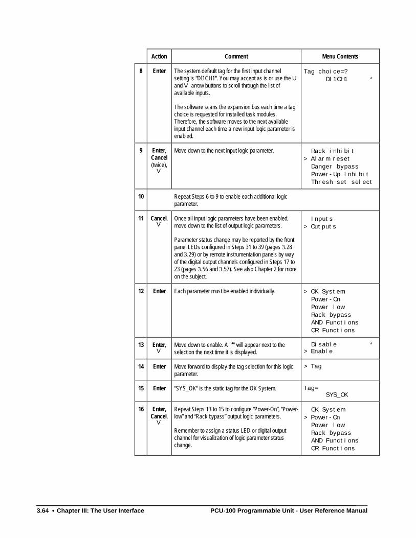
3.64 •••• Chapter III: The User Interface PCU-100 Programmable Unit - User Reference Manual
Action Comment Menu Contents
8 Enter The system default tag for the first input channelsetting is "DI1CH1". You may accept as is or use the Uand V arrow buttons to scroll through the list ofavailable inputs.
The software scans the expansion bus each time a tagchoice is requested for installed task modules.Therefore, the software moves to the next availableinput channel each time a new input logic parameter isenabled.
Tag choice=? DI1CH1 *
9 Enter,Cancel(twice),
V
Move down to the next input logic parameter. Rack inhibit> Alarm reset Danger bypass Power-Up Inhibit Thresh set select
10 Repeat Steps 6 to 9 to enable each additional logicparameter.
11 Cancel,V
Once all input logic parameters have been enabled,move down to the list of output logic parameters.
Parameter status change may be reported by the frontpanel LEDs configured in Steps 31 to 39 (pages 3.28and 3.29) or by remote instrumentation panels by wayof the digital output channels configured in Steps 17 to23 (pages 3.56 and 3.57). See also Chapter 2 for moreon the subject.
Inputs> Outputs
12 Enter Each parameter must be enabled individually. > OK System Power-On Power low Rack bypass AND Functions OR Functions
13 Enter,V
Move down to enable. A "*" will appear next to theselection the next time it is displayed.
Disable *> Enable
14 Enter Move forward to display the tag selection for this logicparameter.
> Tag
15 Enter "SYS_OK" is the static tag for the OK System. Tag= SYS_OK
16 Enter,Cancel,
V
Repeat Steps 13 to 15 to configure “Power-On”, “Power-low” and “Rack bypass” output logic parameters.
Remember to assign a status LED or digital outputchannel for visualization of logic parameter statuschange.
OK System> Power-On Power low Rack bypass AND Functions OR Functions
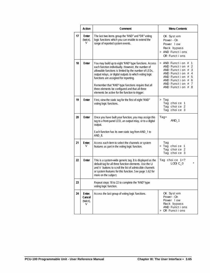
PCU-100 Programmable Unit - User Reference Manual Chapter III: The User Interface •••• 3.65
Action Comment Menu Contents
17 Enter(twice),
V
The last two items group the “AND” and “OR” votinglogic functions which you can enable to extend therange of reported system events.
OK System Power-On Power low Rack bypass> AND Functions OR Functions
18 Enter You may build up to eight “AND”-type functions. Accesseach function individually. However, the number ofallowable functions is limited by the number of LEDs,output relays, or digital outputs to which voting logicfunctions are assigned for reporting.
Remember that “AND”-type functions require that allthree elements be configured and that all threeelements be active for the function to trigger.
> AND Function # 1 AND Function # 2 AND Function # 3 AND Function # 4 AND Function # 5 AND Function # 6 AND Function # 7 AND Function # 8
19 Enter First, view the static tag for the first of eight “AND”voting logic functions.
> Tag Tag choice 1 Tag choice 2 Tag choice 3
20 Enter Once you have built your function, you may assign thistag to a front-panel LED, an output relay, or to a digitaloutput.
Each function has its own static tag from AND_1 toAND_8.
Tag= AND_1
21 Enter,V
Access each item to select the channels or systemfeatures as part in the voting logic function.
Tag> Tag choice 1 Tag choice 2 Tag choice 3
22 Enter This is a system-wide generic tag. It is displayed as thedefault tag for all three function elements. Use the Uand V buttons to scroll the list of admissible channelsor system features for this function. See page 3.62 formore on the subject.
Tag choice 1=? LOGIC_0 *
23 Repeat steps 18 to 22 to complete the “AND”-typevoting logic function.
24 Enter,Cancel(twice),
V
Access the last group of voting logic functions. OK System Power-On Power low Rack bypass AND Functions> OR Functions
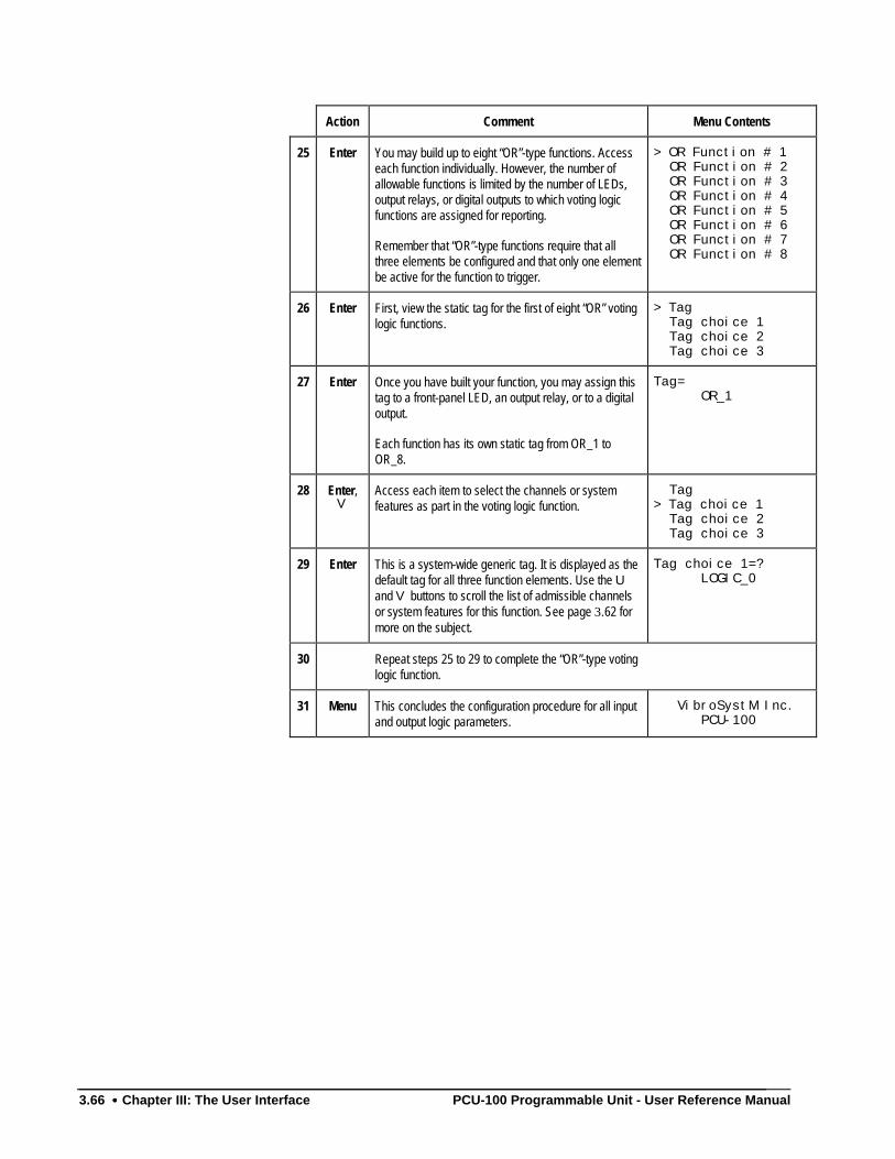
3.66 •••• Chapter III: The User Interface PCU-100 Programmable Unit - User Reference Manual
Action Comment Menu Contents
25 Enter You may build up to eight “OR”-type functions. Accesseach function individually. However, the number ofallowable functions is limited by the number of LEDs,output relays, or digital outputs to which voting logicfunctions are assigned for reporting.
Remember that “OR”-type functions require that allthree elements be configured and that only one elementbe active for the function to trigger.
> OR Function # 1 OR Function # 2 OR Function # 3 OR Function # 4 OR Function # 5 OR Function # 6 OR Function # 7 OR Function # 8
26 Enter First, view the static tag for the first of eight “OR” votinglogic functions.
> Tag Tag choice 1 Tag choice 2 Tag choice 3
27 Enter Once you have built your function, you may assign thistag to a front-panel LED, an output relay, or to a digitaloutput.
Each function has its own static tag from OR_1 toOR_8.
Tag= OR_1
28 Enter,V
Access each item to select the channels or systemfeatures as part in the voting logic function.
Tag> Tag choice 1 Tag choice 2 Tag choice 3
29 Enter This is a system-wide generic tag. It is displayed as thedefault tag for all three function elements. Use the Uand V buttons to scroll the list of admissible channelsor system features for this function. See page 3.62 formore on the subject.
Tag choice 1=? LOGIC_0
30 Repeat steps 25 to 29 to complete the “OR”-type votinglogic function.
31 Menu This concludes the configuration procedure for all inputand output logic parameters.
VibroSystM Inc. PCU-100
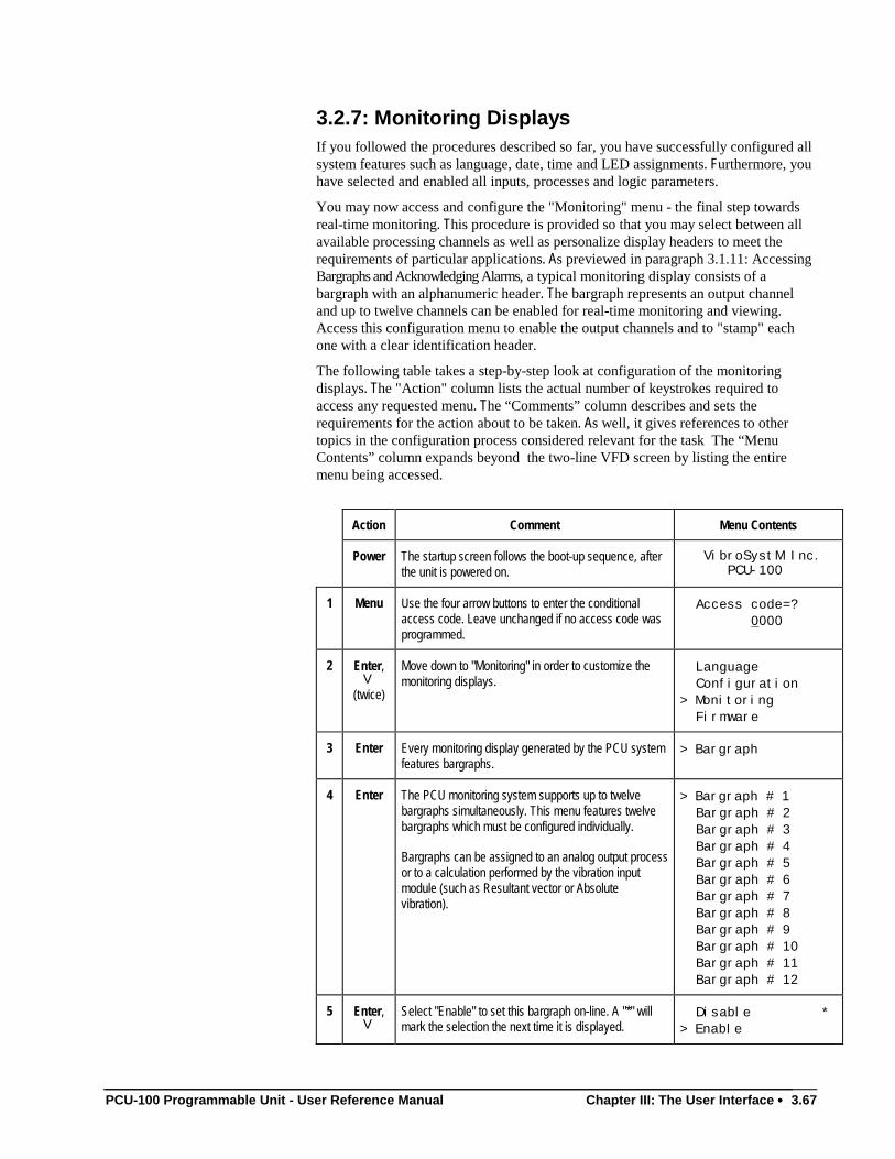
PCU-100 Programmable Unit - User Reference Manual Chapter III: The User Interface •••• 3.67
3.2.7: Monitoring DisplaysIf you followed the procedures described so far, you have successfully configured allsystem features such as language, date, time and LED assignments. Furthermore, youhave selected and enabled all inputs, processes and logic parameters.
You may now access and configure the "Monitoring" menu - the final step towardsreal-time monitoring. This procedure is provided so that you may select between allavailable processing channels as well as personalize display headers to meet therequirements of particular applications. As previewed in paragraph 3.1.11: AccessingBargraphs and Acknowledging Alarms, a typical monitoring display consists of abargraph with an alphanumeric header. The bargraph represents an output channeland up to twelve channels can be enabled for real-time monitoring and viewing.Access this configuration menu to enable the output channels and to "stamp" eachone with a clear identification header.
The following table takes a step-by-step look at configuration of the monitoringdisplays. The "Action" column lists the actual number of keystrokes required toaccess any requested menu. The “Comments” column describes and sets therequirements for the action about to be taken. As well, it gives references to othertopics in the configuration process considered relevant for the task The “MenuContents” column expands beyond the two-line VFD screen by listing the entiremenu being accessed.
Action Comment Menu Contents
Power The startup screen follows the boot-up sequence, afterthe unit is powered on.
VibroSystM Inc. PCU-100
1 Menu Use the four arrow buttons to enter the conditionalaccess code. Leave unchanged if no access code wasprogrammed.
Access code=? 0000
2 Enter,V
(twice)
Move down to "Monitoring" in order to customize themonitoring displays.
Language Configuration> Monitoring Firmware
3 Enter Every monitoring display generated by the PCU systemfeatures bargraphs.
> Bargraph
4 Enter The PCU monitoring system supports up to twelvebargraphs simultaneously. This menu features twelvebargraphs which must be configured individually.
Bargraphs can be assigned to an analog output processor to a calculation performed by the vibration inputmodule (such as Resultant vector or Absolutevibration).
> Bargraph # 1 Bargraph # 2 Bargraph # 3 Bargraph # 4 Bargraph # 5 Bargraph # 6 Bargraph # 7 Bargraph # 8 Bargraph # 9 Bargraph # 10 Bargraph # 11 Bargraph # 12
5 Enter,V
Select "Enable" to set this bargraph on-line. A "*" willmark the selection the next time it is displayed.
Disable *> Enable
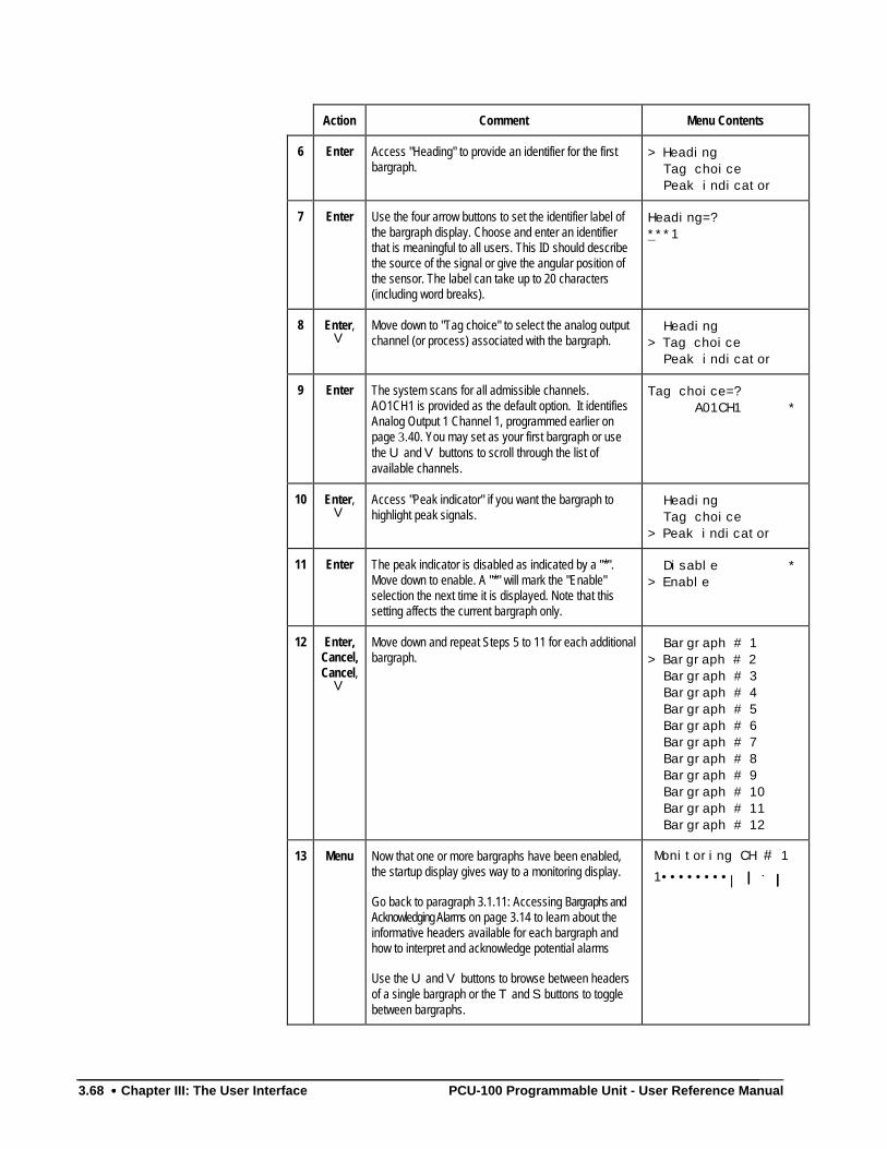
3.68 •••• Chapter III: The User Interface PCU-100 Programmable Unit - User Reference Manual
Action Comment Menu Contents
6 Enter Access "Heading" to provide an identifier for the firstbargraph.
> Heading Tag choice Peak indicator
7 Enter Use the four arrow buttons to set the identifier label ofthe bargraph display. Choose and enter an identifierthat is meaningful to all users. This ID should describethe source of the signal or give the angular position ofthe sensor. The label can take up to 20 characters(including word breaks).
Heading=?***1
8 Enter,V
Move down to "Tag choice" to select the analog outputchannel (or process) associated with the bargraph.
Heading> Tag choice Peak indicator
9 Enter The system scans for all admissible channels.AO1CH1 is provided as the default option. It identifiesAnalog Output 1 Channel 1, programmed earlier onpage 3.40. You may set as your first bargraph or usethe U and V buttons to scroll through the list ofavailable channels.
Tag choice=? A01CH1 *
10 Enter,V
Access "Peak indicator" if you want the bargraph tohighlight peak signals.
Heading Tag choice> Peak indicator
11 Enter The peak indicator is disabled as indicated by a "*".Move down to enable. A "*" will mark the "Enable"selection the next time it is displayed. Note that thissetting affects the current bargraph only.
Disable *> Enable
12 Enter,Cancel,Cancel,
V
Move down and repeat Steps 5 to 11 for each additionalbargraph.
Bargraph # 1> Bargraph # 2 Bargraph # 3 Bargraph # 4 Bargraph # 5 Bargraph # 6 Bargraph # 7 Bargraph # 8 Bargraph # 9 Bargraph # 10 Bargraph # 11 Bargraph # 12
13 Menu Now that one or more bargraphs have been enabled,the startup display gives way to a monitoring display.
Go back to paragraph 3.1.11: Accessing Bargraphs andAcknowledging Alarms on page 3.14 to learn about theinformative headers available for each bargraph andhow to interpret and acknowledge potential alarms
Use the U and V buttons to browse between headersof a single bargraph or the T and S buttons to togglebetween bargraphs.
Monitoring CH # 1 1••••••••| |||| .... ||||
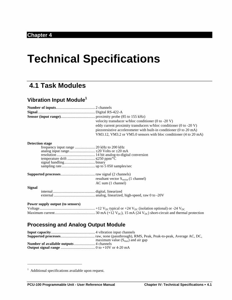
PCU-100 Programmable Unit - User Reference Manual Chapter IV: Technical Specifications •••• 4.1
Chapter 4
Technical Specifications
4.1 Task Modules
Vibration Input Module1
Number of inputs......................................... 2 channelsSignal............................................................ Digital RS-422-ASensor (input range).................................... proximity probe (85 to 155 kHz)
velocity transducer w/bloc conditioner (0 to -20 V)eddy current proximity transducers w/bloc conditioner (0 to -20 V)piezoresistive accelerometer with built-in conditioner (0 to 20 mA)VM3.12, VM3.2 or VM5.0 sensors with bloc conditioner (4 to 20 mA)
Detection stagefrequency input range ..................... 20 kHz to 200 kHzanalog input range........................... ±20 Volts or ±20 mAresolution ........................................ 14 bit analog-to-digital conversiontemperature drift ............................. ≤250 ppm/°Csignal handling................................ binarysampling rate................................... up to 5 050 samples/sec
Supported processes.................................... raw signal (2 channels)resultant vector Svector (1 channel)AC sum (1 channel)
Signalinternal ............................................ digital, linearizedexternal ........................................... analog, linearized, high-speed, raw 0 to -20V
Power supply output (to sensors)Voltage.......................................................... +12 VDC typical or +24 VDC (isolation optional) or -24 VDC
Maximum current.......................................... 30 mA (+12 VDC), 15 mA (24 VDC) short-circuit and thermal protection
Processing and Analog Output ModuleInput capacity.............................................. 4 vibration input channelsSupported processes.................................... raw, none (passthrough), RMS, Peak, Peak-to-peak, Average AC, DC,
maximum value (Smax) and air gapNumber of available outputs ...................... 4 channelsOutput signal range .................................... 0 to +10V or 4-20 mA
1 Additional specifications available upon request.
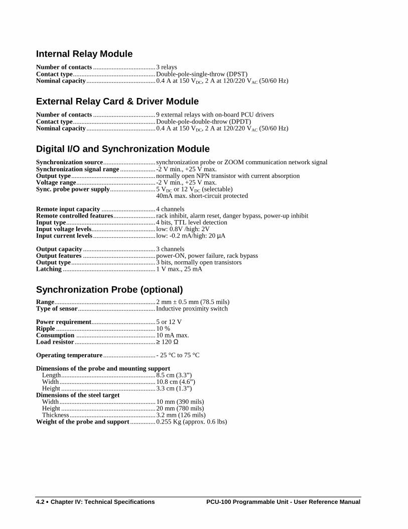
4.2 •••• Chapter IV: Technical Specifications PCU-100 Programmable Unit - User Reference Manual
Internal Relay ModuleNumber of contacts ..................................... 3 relaysContact type.................................................Double-pole-single-throw (DPST)Nominal capacity ......................................... 0.4 A at 150 VDC, 2 A at 120/220 VAC (50/60 Hz)
External Relay Card & Driver ModuleNumber of contacts ..................................... 9 external relays with on-board PCU driversContact type.................................................Double-pole-double-throw (DPDT)Nominal capacity ......................................... 0.4 A at 150 VDC, 2 A at 120/220 VAC (50/60 Hz)
Digital I/O and Synchronization ModuleSynchronization source............................... synchronization probe or ZOOM communication network signalSynchronization signal range ..................... -2 V min., +25 V max.Output type .................................................. normally open NPN transistor with current absorptionVoltage range............................................... -2 V min., +25 V max.Sync. probe power supply........................... 5 VDC or 12 VDC (selectable)
40mA max. short-circuit protected
Remote input capacity ................................ 4 channelsRemote controlled features......................... rack inhibit, alarm reset, danger bypass, power-up inhibitInput type..................................................... 4 bits, TTL level detectionInput voltage levels...................................... low: 0.8V /high: 2VInput current levels ..................................... low: -0.2 mA/high: 20 µA
Output capacity ........................................... 3 channelsOutput features ........................................... power-ON, power failure, rack bypassOutput type .................................................. 3 bits, normally open transistorsLatching ....................................................... 1 V max., 25 mA
Synchronization Probe (optional)Range............................................................ 2 mm ± 0.5 mm (78.5 mils)Type of sensor.............................................. Inductive proximity switch
Power requirement...................................... 5 or 12 VRipple ........................................................... 10 %Consumption ............................................... 10 mA max.Load resistor ................................................≥ 120 Ω
Operating temperature ............................... - 25 °C to 75 °C
Dimensions of the probe and mounting supportLength........................................................ 8.5 cm (3.3”)Width ......................................................... 10.8 cm (4.6”)Height ........................................................ 3.3 cm (1.3”)
Dimensions of the steel targetWidth ......................................................... 10 mm (390 mils)Height ........................................................ 20 mm (780 mils)Thickness................................................... 3.2 mm (126 mils)
Weight of the probe and support ............... 0.255 Kg (approx. 0.6 lbs)
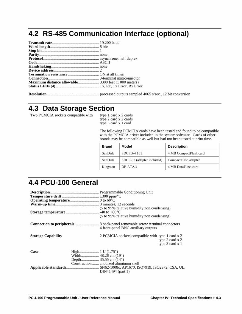
PCU-100 Programmable Unit - User Reference Manual Chapter IV: Technical Specifications •••• 4.3
4.2 RS-485 Communication Interface (optional)Transmit rate............................................... 19.200 baudWord length ................................................. 8 bitsStop bit ......................................................... 1Parity............................................................ noneProtocol ........................................................ asynchrone, half duplexCode.............................................................. ASCIIHandshaking................................................ noneDevice address ............................................. 2Termination resistance ............................... ON at all timesConnection ................................................... 3-terminal miniconnectorMaximum distance allowable ..................... 3300 feet (1 000 meters)Status LEDs (4) ........................................... Tx, Rx, Tx Error, Rx Error
Resolution .................................................... processed outputs sampled 4065 s/sec., 12 bit conversion
4.3 Data Storage SectionTwo PCMCIA sockets compatible with type 1 card x 2 cards
type 2 card x 2 cardstype 3 card x 1 card
The following PCMCIA cards have been tested and found to be compatiblewith the PCMCIA driver included in the system software. Cards of otherbrands may be compatible as well but had not been tested at print time.
Brand Model Description
SanDisk SDCFB-4 101 4 MB CompactFlash card
SanDisk SDCF-03 (adapter included) CompactFlash adapter
Kingston DP-ATA/4 4 MB DataFlash card
4.4 PCU-100 GeneralDescription ................................................. Programmable Conditioning UnitTemperature drift ..................................... ±300 ppm/°COperating temperature ............................. 0 to 60°CWarm-up time............................................ 3 minutes, 12 seconds
(5 to 95% relative humidity non condensing)Storage temperature ................................. -40 to +80°C
(5 to 95% relative humidity non condensing)
Connection to peripherals ........................ 8 back-panel removable screw terminal connectors4 front-panel BNC auxiliary outputs
Storage Capability 2 PCMCIA sockets compatible with type 1 card x 2type 2 card x 2type 3 card x 1
Case High.................... 1 U (1.75")Width.................. 48.26 cm (19“)Depth.................. 35.55 cm (14”)Construction ....... anodized aluminum shell
Applicable standards................................. SN62-1008c, AP1670, ISO7919, ISO2372, CSA, UL,DIN41494 (part 1)
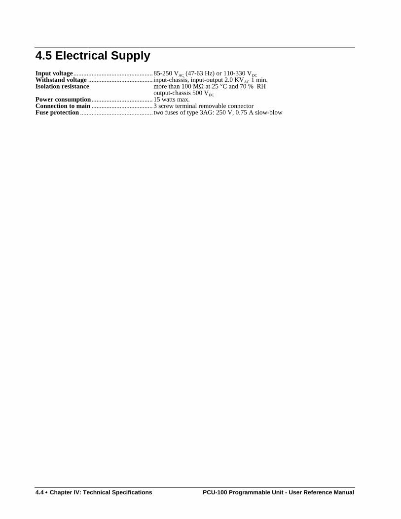
4.4 •••• Chapter IV: Technical Specifications PCU-100 Programmable Unit - User Reference Manual
4.5 Electrical SupplyInput voltage ................................................ 85-250 VAC (47-63 Hz) or 110-330 VDCWithstand voltage ....................................... input-chassis, input-output 2.0 KVAC 1 min.Isolation resistance more than 100 MΩ at 25 °C and 70 % RH
output-chassis 500 VDCPower consumption ..................................... 15 watts max.Connection to main ..................................... 3 screw terminal removable connectorFuse protection ............................................ two fuses of type 3AG: 250 V, 0.75 A slow-blow
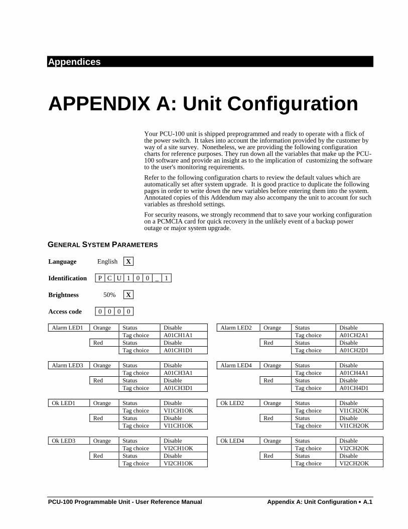
PCU-100 Programmable Unit - User Reference Manual Appendix A: Unit Configuration •••• A.1
Appendices
APPENDIX A: Unit ConfigurationYour PCU-100 unit is shipped preprogrammed and ready to operate with a flick ofthe power switch. It takes into account the information provided by the customer byway of a site survey. Nonetheless, we are providing the following configurationcharts for reference purposes. They run down all the variables that make up the PCU-100 software and provide an insight as to the implication of customizing the softwareto the user's monitoring requirements.
Refer to the following configuration charts to review the default values which areautomatically set after system upgrade. It is good practice to duplicate the followingpages in order to write down the new variables before entering them into the system.Annotated copies of this Addendum may also accompany the unit to account for suchvariables as threshold settings.
For security reasons, we strongly recommend that to save your working configurationon a PCMCIA card for quick recovery in the unlikely event of a backup poweroutage or major system upgrade.
GENERAL SYSTEM PARAMETERS
Language English X
Identification P C U 1 0 0 _ 1
Brightness 50% X
Access code 0 0 0 0
Alarm LED1 Orange Status Disable Alarm LED2 Orange Status DisableTag choice A01CH1A1 Tag choice A01CH2A1
Red Status Disable Red Status DisableTag choice A01CH1D1 Tag choice A01CH2D1
Alarm LED3 Orange Status Disable Alarm LED4 Orange Status DisableTag choice A01CH3A1 Tag choice A01CH4A1
Red Status Disable Red Status DisableTag choice A01CH3D1 Tag choice A01CH4D1
Ok LED1 Orange Status Disable Ok LED2 Orange Status DisableTag choice VI1CH1OK Tag choice VI1CH2OK
Red Status Disable Red Status DisableTag choice VI1CH1OK Tag choice VI1CH2OK
Ok LED3 Orange Status Disable Ok LED4 Orange Status DisableTag choice VI2CH1OK Tag choice VI2CH2OK
Red Status Disable Red Status DisableTag choice VI2CH1OK Tag choice VI2CH2OK
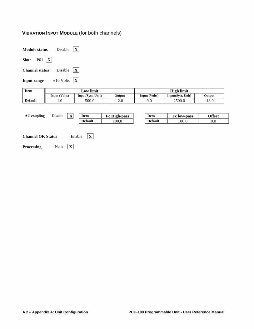
A.2 •••• Appendix A: Unit Configuration PCU-100 Programmable Unit - User Reference Manual
VIBRATION INPUT MODULE (for both channels)
Module status Disable X
Slot: P01 X
Channel status Disable X
Input range ±10 Volts X
Item Low limit High limitInput (Volts) Input(Syst. Unit) Output Input (Volts) Input(Syst. Unit) Output
Default 1.0 500.0 -2.0 9.0 2500.0 -18.0
AC coupling Disable X Item Fc High-pass Item Fc low-pass OffsetDefault 100.0 Default 100.0 0.0
Channel OK Status Enable X
Processing None X
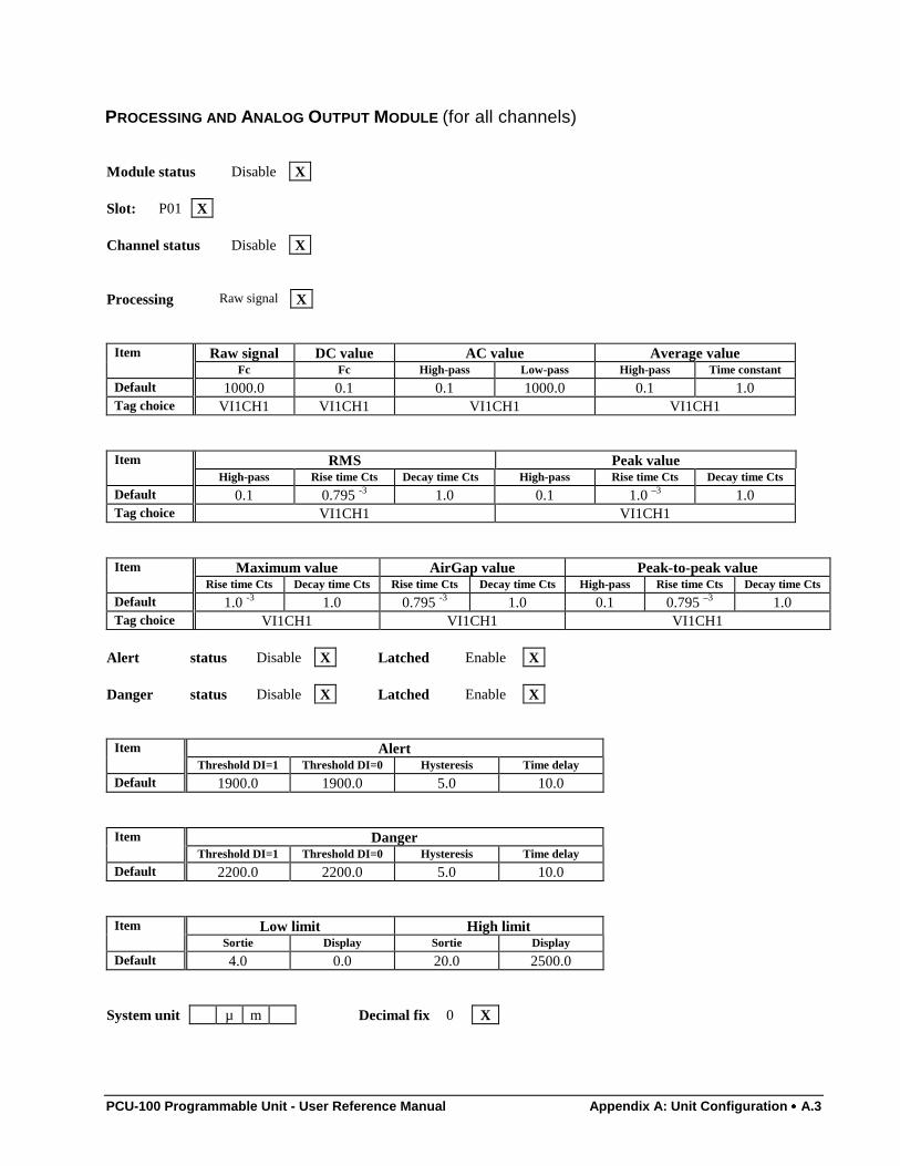
PCU-100 Programmable Unit - User Reference Manual Appendix A: Unit Configuration •••• A.3
PROCESSING AND ANALOG OUTPUT MODULE (for all channels)
Module status Disable X
Slot: P01 X
Channel status Disable X
Processing Raw signal X
Item Raw signal DC value AC value Average valueFc Fc High-pass Low-pass High-pass Time constant
Default 1000.0 0.1 0.1 1000.0 0.1 1.0Tag choice VI1CH1 VI1CH1 VI1CH1 VI1CH1
Item RMS Peak valueHigh-pass Rise time Cts Decay time Cts High-pass Rise time Cts Decay time Cts
Default 0.1 0.795 -3 1.0 0.1 1.0 –3 1.0Tag choice VI1CH1 VI1CH1
Item Maximum value AirGap value Peak-to-peak valueRise time Cts Decay time Cts Rise time Cts Decay time Cts High-pass Rise time Cts Decay time Cts
Default 1.0 -3 1.0 0.795 -3 1.0 0.1 0.795 –3 1.0Tag choice VI1CH1 VI1CH1 VI1CH1
Alert status Disable X Latched Enable X
Danger status Disable X Latched Enable X
Item AlertThreshold DI=1 Threshold DI=0 Hysteresis Time delay
Default 1900.0 1900.0 5.0 10.0
Item DangerThreshold DI=1 Threshold DI=0 Hysteresis Time delay
Default 2200.0 2200.0 5.0 10.0
Item Low limit High limitSortie Display Sortie Display
Default 4.0 0.0 20.0 2500.0
System unit µ m Decimal fix 0 X
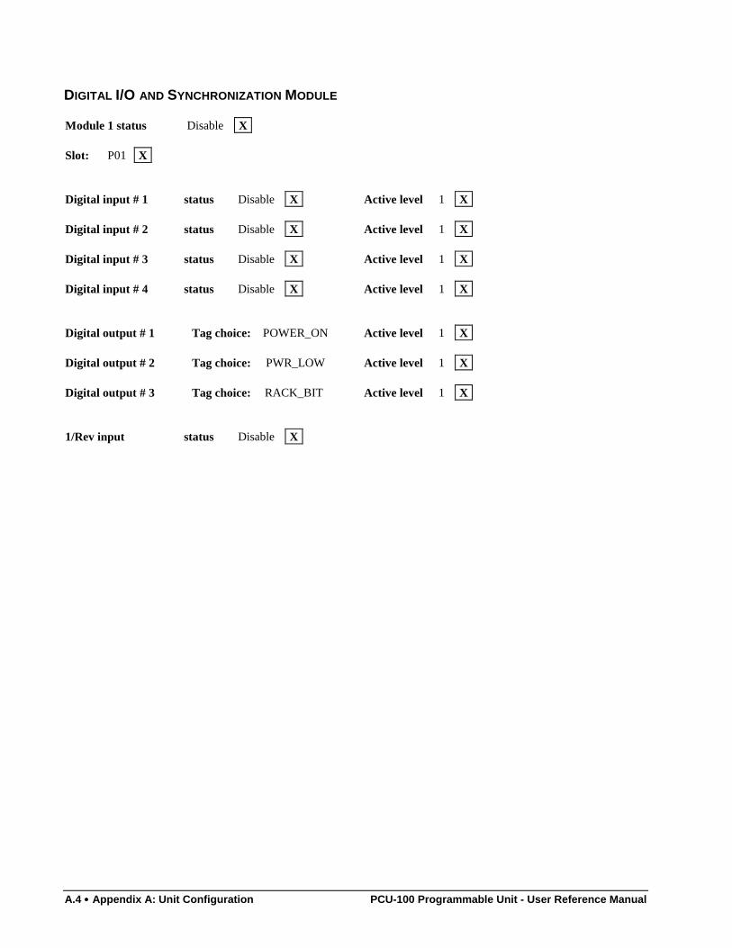
A.4 •••• Appendix A: Unit Configuration PCU-100 Programmable Unit - User Reference Manual
DIGITAL I/O AND SYNCHRONIZATION MODULE
Module 1 status Disable X
Slot: P01 X
Digital input # 1 status Disable X Active level 1 X
Digital input # 2 status Disable X Active level 1 X
Digital input # 3 status Disable X Active level 1 X
Digital input # 4 status Disable X Active level 1 X
Digital output # 1 Tag choice: POWER_ON Active level 1 X
Digital output # 2 Tag choice: PWR_LOW Active level 1 X
Digital output # 3 Tag choice: RACK_BIT Active level 1 X
1/Rev input status Disable X
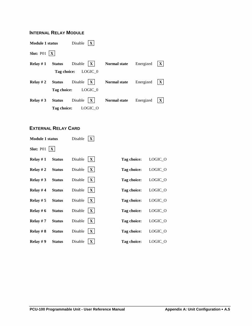
PCU-100 Programmable Unit - User Reference Manual Appendix A: Unit Configuration •••• A.5
INTERNAL RELAY MODULE
Module 1 status Disable X
Slot: P01 X
Relay # 1 Status Disable X Normal state Energized X
Tag choice: LOGIC_0
Relay # 2 Status Disable X Normal state Energized X
Tag choice: LOGIC_0
Relay # 3 Status Disable X Normal state Energized X
Tag choice: LOGIC_O
EXTERNAL RELAY CARD
Module 1 status Disable X
Slot: P01 X
Relay # 1 Status Disable X Tag choice: LOGIC_O
Relay # 2 Status Disable X Tag choice: LOGIC_O
Relay # 3 Status Disable X Tag choice: LOGIC_O
Relay # 4 Status Disable X Tag choice: LOGIC_O
Relay # 5 Status Disable X Tag choice: LOGIC_O
Relay # 6 Status Disable X Tag choice: LOGIC_O
Relay # 7 Status Disable X Tag choice: LOGIC_O
Relay # 8 Status Disable X Tag choice: LOGIC_O
Relay # 9 Status Disable X Tag choice: LOGIC_O
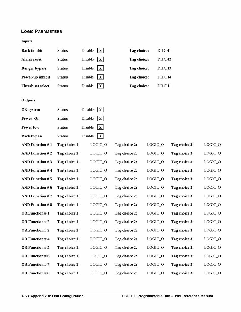
A.6 •••• Appendix A: Unit Configuration PCU-100 Programmable Unit - User Reference Manual
LOGIC PARAMETERS
Inputs
Rack inhibit Status Disable X Tag choice: DI1CH1
Alarm reset Status Disable X Tag choice: DI1CH2
Danger bypass Status Disable X Tag choice: DI1CH3
Power-up inhibit Status Disable X Tag choice: DI1CH4
Thresh set select Status Disable X Tag choice: DI1CH1
Outputs
OK system Status Disable X
Power_On Status Disable X
Power low Status Disable X
Rack bypass Status Disable X
AND Function # 1 Tag choice 1: LOGIC_O Tag choice 2: LOGIC_O Tag choice 3: LOGIC_O
AND Function # 2 Tag choice 1: LOGIC_O Tag choice 2: LOGIC_O Tag choice 3: LOGIC_O
AND Function # 3 Tag choice 1: LOGIC_O Tag choice 2: LOGIC_O Tag choice 3: LOGIC_O
AND Function # 4 Tag choice 1: LOGIC_O Tag choice 2: LOGIC_O Tag choice 3: LOGIC_O
AND Function # 5 Tag choice 1: LOGIC_O Tag choice 2: LOGIC_O Tag choice 3: LOGIC_O
AND Function # 6 Tag choice 1: LOGIC_O Tag choice 2: LOGIC_O Tag choice 3: LOGIC_O
AND Function # 7 Tag choice 1: LOGIC_O Tag choice 2: LOGIC_O Tag choice 3: LOGIC_O
AND Function # 8 Tag choice 1: LOGIC_O Tag choice 2: LOGIC_O Tag choice 3: LOGIC_O
OR Function # 1 Tag choice 1: LOGIC_O Tag choice 2: LOGIC_O Tag choice 3: LOGIC_O
OR Function # 2 Tag choice 1: LOGIC_O Tag choice 2: LOGIC_O Tag choice 3: LOGIC_O
OR Function # 3 Tag choice 1: LOGIC_O Tag choice 2: LOGIC_O Tag choice 3: LOGIC_O
OR Function # 4 Tag choice 1: LOGIC_O Tag choice 2: LOGIC_O Tag choice 3: LOGIC_O
OR Function # 5 Tag choice 1: LOGIC_O Tag choice 2: LOGIC_O Tag choice 3: LOGIC_O
OR Function # 6 Tag choice 1: LOGIC_O Tag choice 2: LOGIC_O Tag choice 3: LOGIC_O
OR Function # 7 Tag choice 1: LOGIC_O Tag choice 2: LOGIC_O Tag choice 3: LOGIC_O
OR Function # 8 Tag choice 1: LOGIC_O Tag choice 2: LOGIC_O Tag choice 3: LOGIC_O
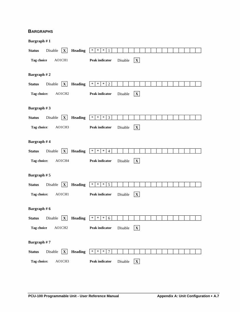
PCU-100 Programmable Unit - User Reference Manual Appendix A: Unit Configuration •••• A.7
BARGRAPHS
Bargraph # 1
Status Disable X Heading * * * 1
Tag choice AO1CH1 Peak indicator Disable X
Bargraph # 2
Status Disable X Heading * * * 2
Tag choice: AO1CH2 Peak indicator Disable X
Bargraph # 3
Status Disable X Heading * * * 3
Tag choice: AO1CH3 Peak indicator Disable X
Bargraph # 4
Status Disable X Heading * * * 4
Tag choice: AO1CH4 Peak indicator Disable X
Bargraph # 5
Status Disable X Heading * * * 5
Tag choice: AO1CH1 Peak indicator Disable X
Bargraph # 6
Status Disable X Heading * * * 6
Tag choice AO1CH2 Peak indicator Disable X
Bargraph # 7
Status Disable X Heading * * * 7
Tag choice: AO1CH3 Peak indicator Disable X
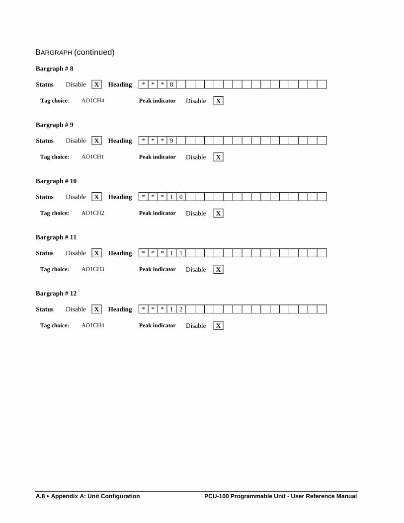
A.8 •••• Appendix A: Unit Configuration PCU-100 Programmable Unit - User Reference Manual
BARGRAPH (continued)
Bargraph # 8
Status Disable X Heading * * * 8
Tag choice: AO1CH4 Peak indicator Disable X
Bargraph # 9
Status Disable X Heading * * * 9
Tag choice: AO1CH1 Peak indicator Disable X
Bargraph # 10
Status Disable X Heading * * * 1 0
Tag choice: AO1CH2 Peak indicator Disable X
Bargraph # 11
Status Disable X Heading * * * 1 1
Tag choice: AO1CH3 Peak indicator Disable X
Bargraph # 12
Status Disable X Heading * * * 1 2
Tag choice: AO1CH4 Peak indicator Disable X
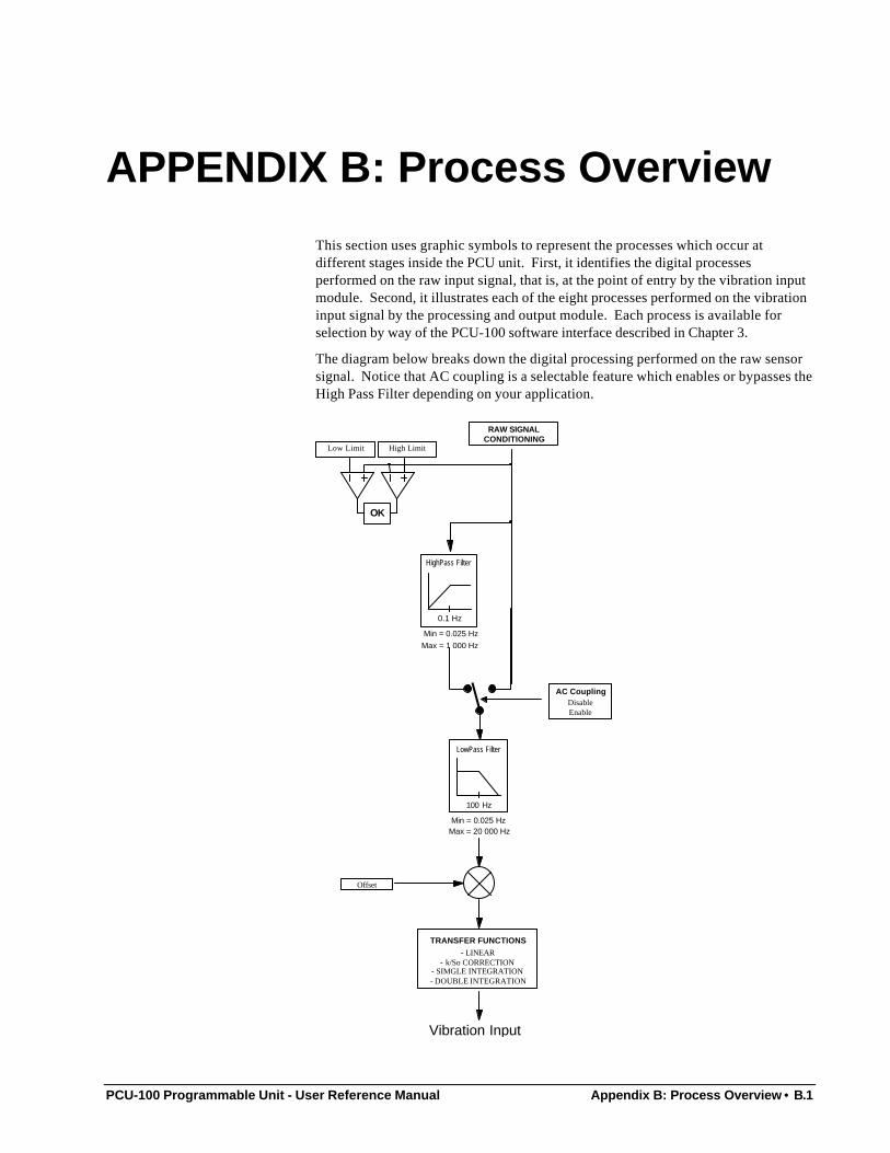
PCU-100 Programmable Unit - User Reference Manual Appendix B: Process Overview • B.1
APPENDIX B: Process Overview
This section uses graphic symbols to represent the processes which occur atdifferent stages inside the PCU unit. First, it identifies the digital processesperformed on the raw input signal, that is, at the point of entry by the vibration inputmodule. Second, it illustrates each of the eight processes performed on the vibrationinput signal by the processing and output module. Each process is available forselection by way of the PCU-100 software interface described in Chapter 3.
The diagram below breaks down the digital processing performed on the raw sensorsignal. Notice that AC coupling is a selectable feature which enables or bypasses theHigh Pass Filter depending on your application.
RAW SIGNALCONDITIONING
High LimitLow Limit
OK
0.1 Hz
Min = 0.025 HzMax = 1 000 Hz
HighPass Filter
AC CouplingDisableEnable
100 Hz
Min = 0.025 HzMax = 20 000 Hz
LowPass Filter
Offset
TRANSFER FUNCTIONS- LINEAR
- k/So CORRECTION- SIMGLE INTEGRATION- DOUBLE INTEGRATION
Vibration Input
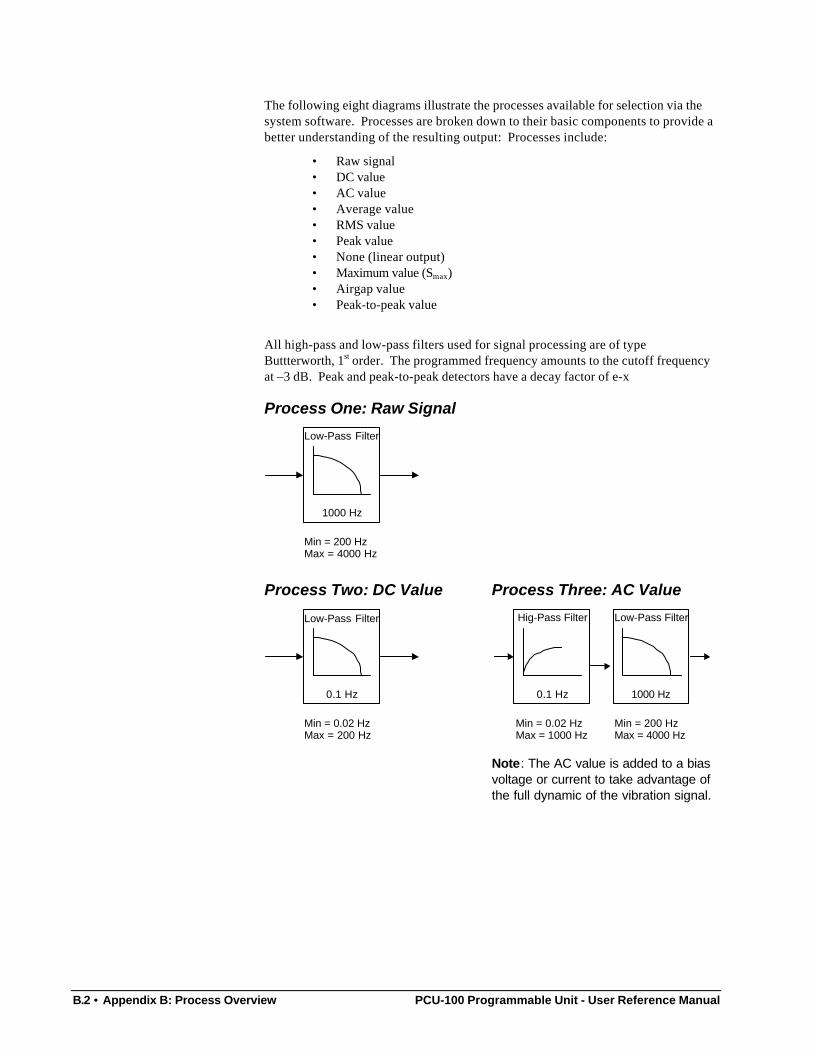
B.2 • Appendix B: Process Overview PCU-100 Programmable Unit - User Reference Manual
The following eight diagrams illustrate the processes available for selection via thesystem software. Processes are broken down to their basic components to provide abetter understanding of the resulting output: Processes include:
• Raw signal• DC value• AC value• Average value• RMS value• Peak value• None (linear output)• Maximum value (Smax)• Airgap value• Peak-to-peak value
All high-pass and low-pass filters used for signal processing are of typeButtterworth, 1st order. The programmed frequency amounts to the cutoff frequencyat –3 dB. Peak and peak-to-peak detectors have a decay factor of e-x
Process One: Raw Signal
1000 Hz
Min = 200 HzMax = 4000 Hz
Low-Pass Filter
Process Two: DC Value
0.1 Hz
Min = 0.02 HzMax = 200 Hz
Low-Pass Filter
Process Three: AC Value
0.1 Hz 1000 Hz
Min = 0.02 HzMax = 1000 Hz
Min = 200 HzMax = 4000 Hz
Low-Pass FilterHig-Pass Filter
Note: The AC value is added to a biasvoltage or current to take advantage ofthe full dynamic of the vibration signal.
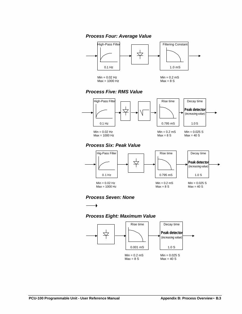
PCU-100 Programmable Unit - User Reference Manual Appendix B: Process Overview • B.3
Process Four: Average Value
0.1 Hz 1.0 mS
Min = 0.02 HzMax = 1000 Hz
Min = 0.2 mSMax = 8 S
High-Pass Filter Filtering Constant
Process Five: RMS Value
1.0 S0.1 Hz 0.795 mS
Min = 0.02 HzMax = 1000 Hz
Min = 0.2 mSMax = 8 S
Min = 0.025 SMax = 40 S
Rise time Decay timeHigh-Pass Filter
Peak detector(increasing value)
Process Six: Peak Value
1.0 S
Peak detector(increasing value)
0.1 Hz 0.795 mS
Min = 0.02 HzMax = 1000 Hz
Min = 0.2 mSMax = 8 S
Min = 0.025 SMax = 40 S
Hig-Pass Filter Rise time Decay time
Process Seven: None
Process Eight: Maximum Value
1.0 S0.001 mS
Rise time Decay time
Peak detector(increasing value)
Min = 0.2 mSMax = 8 S
Min = 0.025 SMax = 40 S
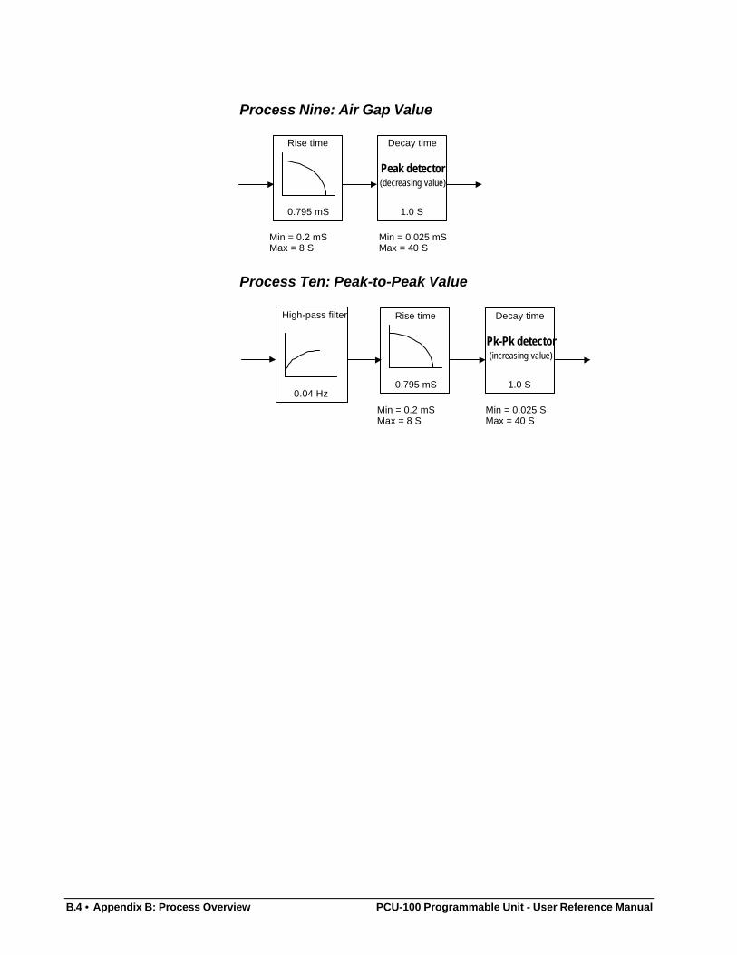
B.4 • Appendix B: Process Overview PCU-100 Programmable Unit - User Reference Manual
Process Nine: Air Gap Value
1.0 S0.795 mS
Rise time Decay time
Peak detector(decreasing value)
Min = 0.2 mSMax = 8 S
Min = 0.025 mSMax = 40 S
Process Ten: Peak-to-Peak Value
1.0 S0.795 mS
Rise time Decay time
Pk-Pk detector(increasing value)
Min = 0.2 mSMax = 8 S
Min = 0.025 SMax = 40 S
0.04 Hz
High-pass filter
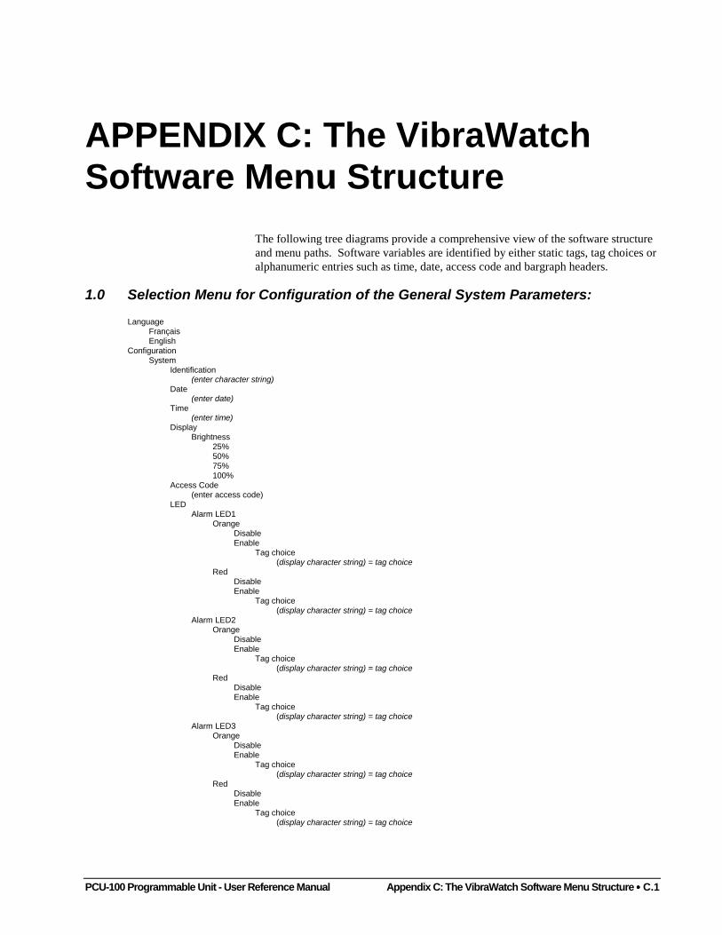
PCU-100 Programmable Unit - User Reference Manual Appendix C: The VibraWatch Software Menu Structure •••• C.1
APPENDIX C: The VibraWatchSoftware Menu Structure
The following tree diagrams provide a comprehensive view of the software structureand menu paths. Software variables are identified by either static tags, tag choices oralphanumeric entries such as time, date, access code and bargraph headers.
1.0 Selection Menu for Configuration of the General System Parameters:
LanguageFrançaisEnglish
ConfigurationSystem
Identification(enter character string)
Date(enter date)
Time(enter time)
DisplayBrightness
25%50%75%100%
Access Code(enter access code)
LEDAlarm LED1
OrangeDisableEnable
Tag choice(display character string) = tag choice
RedDisableEnable
Tag choice(display character string) = tag choice
Alarm LED2Orange
DisableEnable
Tag choice(display character string) = tag choice
RedDisableEnable
Tag choice(display character string) = tag choice
Alarm LED3Orange
DisableEnable
Tag choice(display character string) = tag choice
RedDisableEnable
Tag choice(display character string) = tag choice
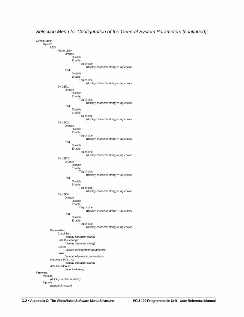
C.2 •••• Appendix C: The VibraWatch Software Menu Structure PCU-100 Programmable Unit - User Reference Manual
Selection Menu for Configuration of the General System Parameters (continued):
ConfigurationSystem
LEDAlarm LED4
OrangeDisableEnable
Tag choice(display character string) = tag choice
RedDisableEnable
Tag choice(display character string) = tag choice
Ok LED1Orange
DisableEnable
Tag choice(display character string) = tag choice
RedDisableEnable
Tag choice(display character string) = tag choice
Ok LED2Orange
DisableEnable
Tag choice(display character string) = tag choice
RedDisableEnable
Tag choice(display character string) = tag choice
Ok LED3Orange
DisableEnable
Tag choice(display character string) = tag choice
RedDisableEnable
Tag choice(display character string) = tag choice
Ok LED4Orange
DisableEnable
Tag choice(display character string) = tag choice
RedDisableEnable
Tag choice(display character string) = tag choice
ParametersCheckSum
(display character string)Date last change
(display character string)Update
(update configuration parameters)Save
(save configuration parameters)Hardware P08… 01
(display character string)485 link address
(select address)Firmware
Version(display version number)
Update(update firmware)
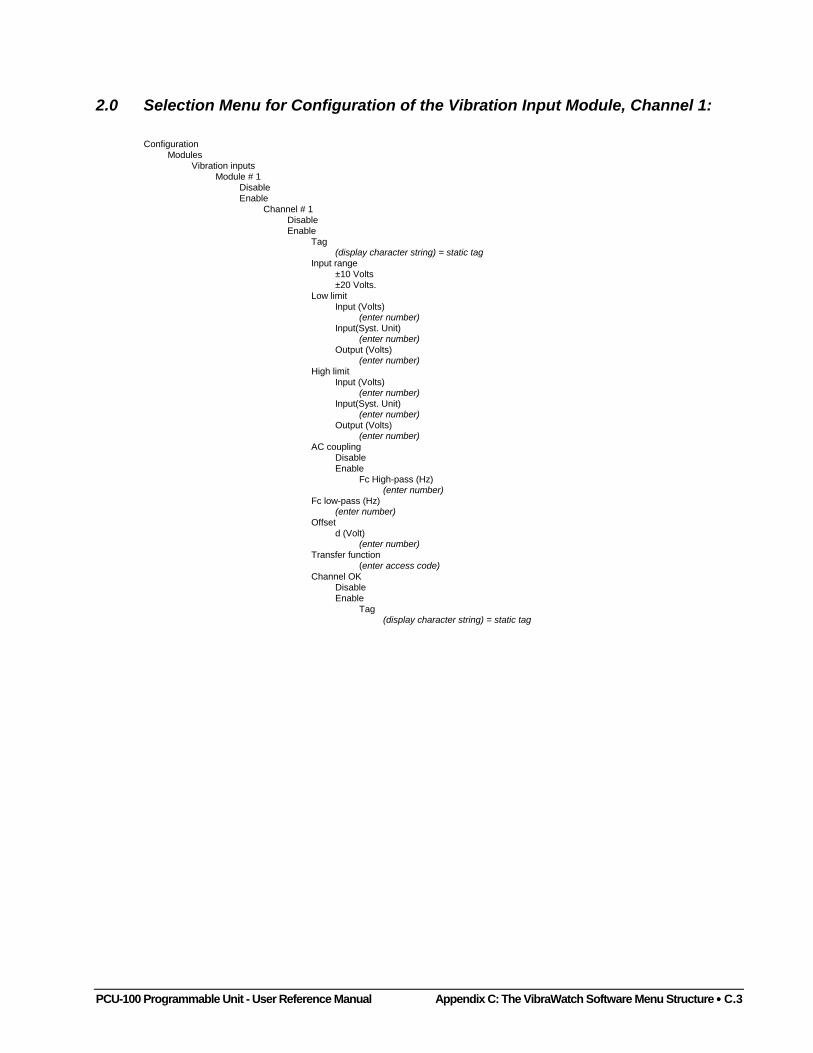
PCU-100 Programmable Unit - User Reference Manual Appendix C: The VibraWatch Software Menu Structure •••• C.3
2.0 Selection Menu for Configuration of the Vibration Input Module, Channel 1:
ConfigurationModules
Vibration inputsModule # 1
DisableEnable
Channel # 1DisableEnable
Tag(display character string) = static tag
Input range±10 Volts±20 Volts.
Low limitInput (Volts)
(enter number)Input(Syst. Unit)
(enter number)Output (Volts)
(enter number)High limit
Input (Volts)(enter number)
Input(Syst. Unit)(enter number)
Output (Volts)(enter number)
AC couplingDisableEnable
Fc High-pass (Hz)(enter number)
Fc low-pass (Hz)(enter number)
Offsetd (Volt)
(enter number)Transfer function
(enter access code)Channel OK
DisableEnable
Tag(display character string) = static tag
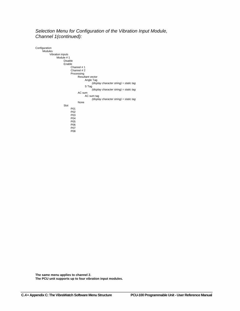
C.4 •••• Appendix C: The VibraWatch Software Menu Structure PCU-100 Programmable Unit - User Reference Manual
Selection Menu for Configuration of the Vibration Input Module,Channel 1(continued):
ConfigurationModules
Vibration inputsModule # 1
DisableEnable
Channel # 1Channel # 2Processing
Resultant vectorAngle Tag
(display character string) = static tagS Tag
(display character string) = static tagAC sum
AC sum tag(display character string) = static tag
NoneSlot
P01P02P03P04P05P06P07P08
The same menu applies to channel 2.The PCU unit supports up to four vibration input modules.

PCU-100 Programmable Unit - User Reference Manual Appendix C: The VibraWatch Software Menu Structure •••• C.5
2.1 Selection Menu for Configuration of the Processing and Analog OutputModule, Channel 1:
ConfigurationModules
Analog outputsModule # 1
DisableEnable
Channel # 1DisableEnable
Tag(display character string) = static tag
ProcessingRaw signal
Tag choice(display character string) = tag choice
Fc low-pass (Hz)(enter number)
DC ValueTag choice
(display character string) = tag choiceFc low-pass (Hz)
(enter number)AC value
Tag choice(display character string) = tag choice
Fc high-pass (Hz)(enter number)
Fc low-pass (Hz)(enter number)
Average valueTag choice
(display character string) = tag choiceFc high-pass (Hz)
(enter number)Time cts (Sec)
(enter number)RMS
Tag choice(display character string) = tag choice
Fc high-pass (Hz)(enter number)
Rise time (Sec)(enter number)
Decay time (Sec)(enter number)
Peak valueTag choice
(display character string) = tag choiceFc high-pass (Hz)
(enter number)Rise time (Sec)
(enter number)Decay time (Sec)
(enter number)Nothing
Tag choice(display character string) = tag choice
Maximum valueTag choice
(display character string) = tag choiceRise time (Sec)
(enter number)Decay time (Sec)
(enter number)Airgap value
Tag choice(display character string) = tag choice
Rise time (Sec)(enter number)
Decay time (Sec)(enter number)
Peak-to-peak valueTag choice
(display character string) = tag choiceFc high-pass (Hz)
(enter number)Rise time (Sec)
(enter number)Decay time (Sec)
(enter number)
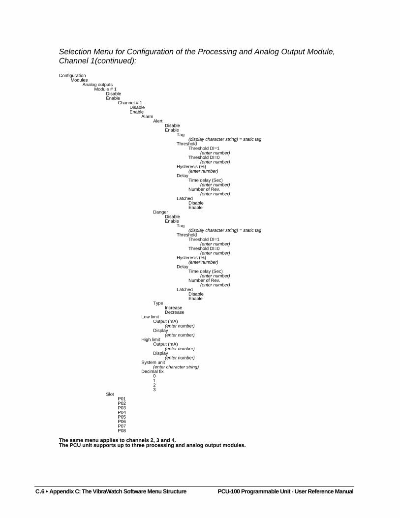
C.6 •••• Appendix C: The VibraWatch Software Menu Structure PCU-100 Programmable Unit - User Reference Manual
Selection Menu for Configuration of the Processing and Analog Output Module,Channel 1(continued):
ConfigurationModules
Analog outputsModule # 1
DisableEnable
Channel # 1DisableEnable
AlarmAlert
DisableEnable
Tag(display character string) = static tag
ThresholdThreshold DI=1
(enter number)Threshold DI=0
(enter number)Hysteresis (%)
(enter number)Delay
Time delay (Sec)(enter number)
Number of Rev.(enter number)
LatchedDisableEnable
DangerDisableEnable
Tag(display character string) = static tag
ThresholdThreshold DI=1
(enter number)Threshold DI=0
(enter number)Hysteresis (%)
(enter number)Delay
Time delay (Sec)(enter number)
Number of Rev.(enter number)
LatchedDisableEnable
TypeIncreaseDecrease
Low limitOutput (mA)
(enter number)Display
(enter number)High limit
Output (mA)(enter number)
Display(enter number)
System unit(enter character string)
Decimal fix0123
SlotP01P02P03P04P05P06P07P08
The same menu applies to channels 2, 3 and 4.The PCU unit supports up to three processing and analog output modules.
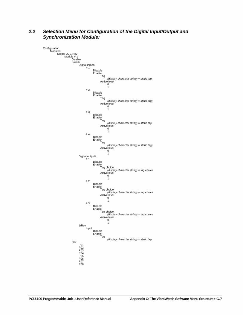
PCU-100 Programmable Unit - User Reference Manual Appendix C: The VibraWatch Software Menu Structure •••• C.7
2.2 Selection Menu for Configuration of the Digital Input/Output andSynchronization Module:
ConfigurationModules
Digital I/O 1\RevModule # 1
DisableEnable
Digital inputs# 1
DisableEnable
Tag(display character string) = static tag
Active level01
# 2DisableEnable
Tag(display character string) = static tag)
Active level01
# 3DisableEnable
Tag(display character string) = static tag
Active level01
# 4DisableEnable
Tag(display character string) = static tag)
Active level01
Digital outputs# 1
DisableEnable
Tag choice(display character string) = tag choice
Active level01
# 2DisableEnable
Tag choice(display character string) = tag choice
Active level01
# 3DisableEnable
Tag choice(display character string) = tag choice
Active level01
1/RevInput
DisableEnable
Tag(display character string) = static tag
SlotP01P02P03P04P05P06P07P08
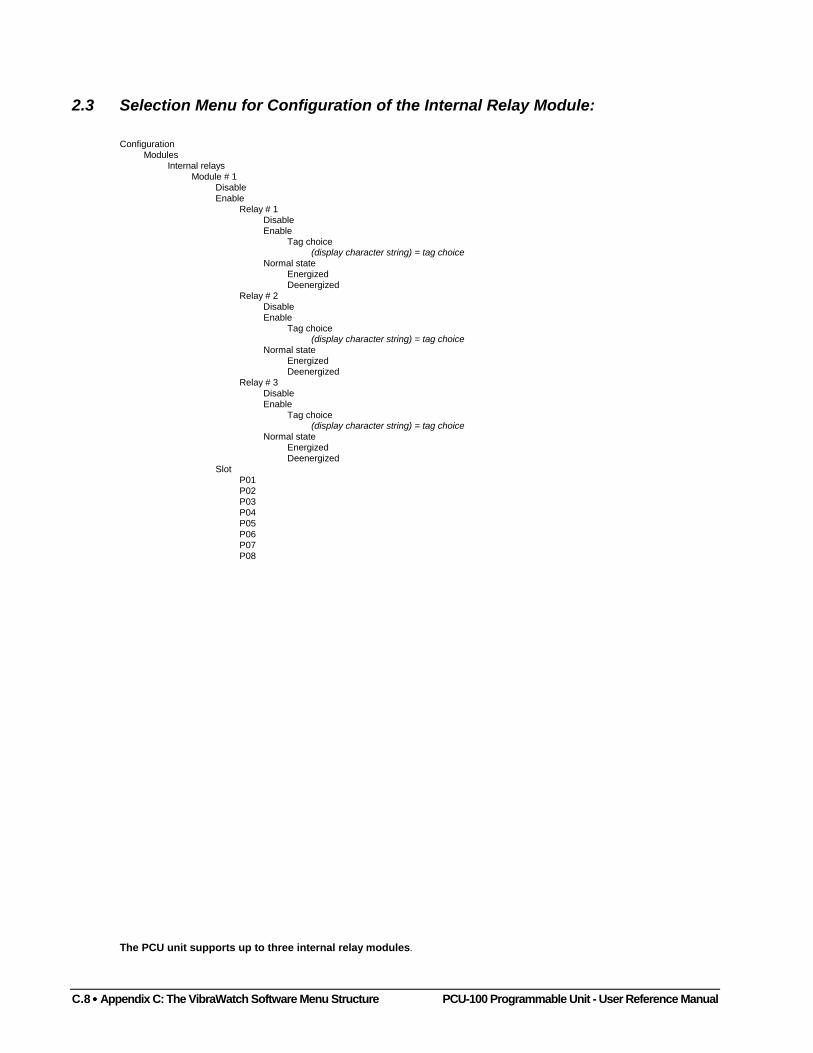
C.8 •••• Appendix C: The VibraWatch Software Menu Structure PCU-100 Programmable Unit - User Reference Manual
2.3 Selection Menu for Configuration of the Internal Relay Module:
ConfigurationModules
Internal relaysModule # 1
DisableEnable
Relay # 1DisableEnable
Tag choice(display character string) = tag choice
Normal stateEnergizedDeenergized
Relay # 2DisableEnable
Tag choice(display character string) = tag choice
Normal stateEnergizedDeenergized
Relay # 3DisableEnable
Tag choice(display character string) = tag choice
Normal stateEnergizedDeenergized
SlotP01P02P03P04P05P06P07P08
The PCU unit supports up to three internal relay modules.
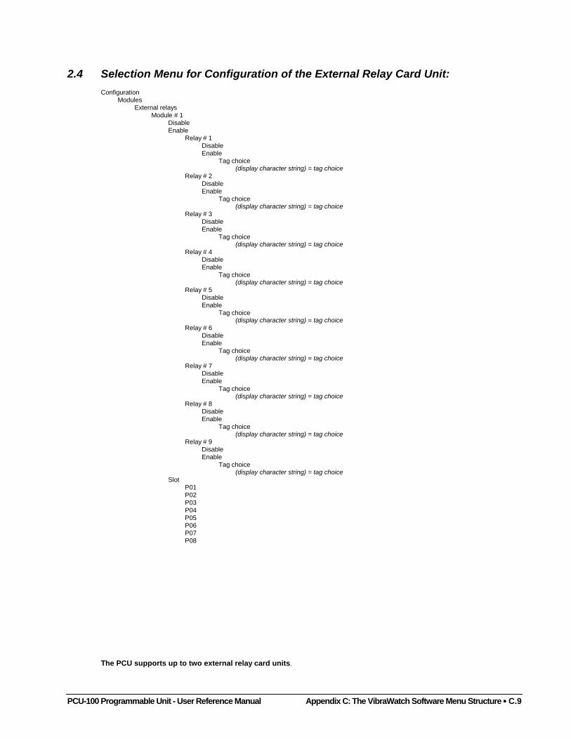
PCU-100 Programmable Unit - User Reference Manual Appendix C: The VibraWatch Software Menu Structure •••• C.9
2.4 Selection Menu for Configuration of the External Relay Card Unit:Configuration
ModulesExternal relays
Module # 1DisableEnable
Relay # 1DisableEnable
Tag choice(display character string) = tag choice
Relay # 2DisableEnable
Tag choice(display character string) = tag choice
Relay # 3DisableEnable
Tag choice(display character string) = tag choice
Relay # 4DisableEnable
Tag choice(display character string) = tag choice
Relay # 5DisableEnable
Tag choice(display character string) = tag choice
Relay # 6DisableEnable
Tag choice(display character string) = tag choice
Relay # 7DisableEnable
Tag choice(display character string) = tag choice
Relay # 8DisableEnable
Tag choice(display character string) = tag choice
Relay # 9DisableEnable
Tag choice(display character string) = tag choice
SlotP01P02P03P04P05P06P07P08
The PCU supports up to two external relay card units.
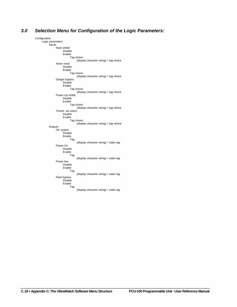
C.10 •••• Appendix C: The VibraWatch Software Menu Structure PCU-100 Programmable Unit - User Reference Manual
3.0 Selection Menu for Configuration of the Logic Parameters:Configuration
Logic parametersInputs
Rack inhibitDisableEnable
Tag choice(display character string) = tag choice
Alarm resetDisableEnable
Tag choice(display character string) = tag choice
Danger bypassDisableEnable
Tag choice(display character string) = tag choice
Power-Up inhibitDisableEnable
Tag choice(display character string) = tag choice
Thresh set selectDisableEnable
Tag choice(display character string) = tag choice
OutputsOK system
DisableEnable
Tag(display character string) = static tag
Power-OnDisableEnable
Tag(display character string) = static tag
Power lowDisableEnable
Tag(display character string) = static tag
Rack bypassDisableEnable
Tag(display character string) = static tag
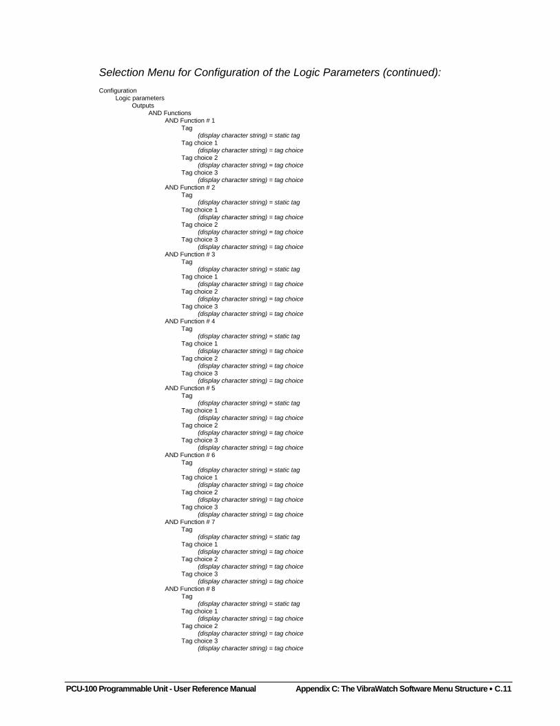
PCU-100 Programmable Unit - User Reference Manual Appendix C: The VibraWatch Software Menu Structure •••• C.11
Selection Menu for Configuration of the Logic Parameters (continued):Configuration
Logic parametersOutputs
AND FunctionsAND Function # 1
Tag(display character string) = static tag
Tag choice 1(display character string) = tag choice
Tag choice 2(display character string) = tag choice
Tag choice 3(display character string) = tag choice
AND Function # 2Tag
(display character string) = static tagTag choice 1
(display character string) = tag choiceTag choice 2
(display character string) = tag choiceTag choice 3
(display character string) = tag choiceAND Function # 3
Tag(display character string) = static tag
Tag choice 1(display character string) = tag choice
Tag choice 2(display character string) = tag choice
Tag choice 3(display character string) = tag choice
AND Function # 4Tag
(display character string) = static tagTag choice 1
(display character string) = tag choiceTag choice 2
(display character string) = tag choiceTag choice 3
(display character string) = tag choiceAND Function # 5
Tag(display character string) = static tag
Tag choice 1(display character string) = tag choice
Tag choice 2(display character string) = tag choice
Tag choice 3(display character string) = tag choice
AND Function # 6Tag
(display character string) = static tagTag choice 1
(display character string) = tag choiceTag choice 2
(display character string) = tag choiceTag choice 3
(display character string) = tag choiceAND Function # 7
Tag(display character string) = static tag
Tag choice 1(display character string) = tag choice
Tag choice 2(display character string) = tag choice
Tag choice 3(display character string) = tag choice
AND Function # 8Tag
(display character string) = static tagTag choice 1
(display character string) = tag choiceTag choice 2
(display character string) = tag choiceTag choice 3
(display character string) = tag choice
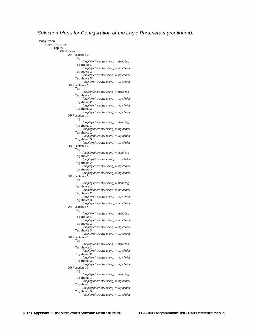
C.12 •••• Appendix C: The VibraWatch Software Menu Structure PCU-100 Programmable Unit - User Reference Manual
Selection Menu for Configuration of the Logic Parameters (continued):Configuration
Logic parametersOutputs
OR FunctionsOR Function # 1
Tag(display character string) = static tag
Tag choice 1(display character string) = tag choice
Tag choice 2(display character string) = tag choice
Tag choice 3(display character string) = tag choice
OR Function # 2Tag
(display character string) = static tagTag choice 1
(display character string) = tag choiceTag choice 2
(display character string) = tag choiceTag choice 3
(display character string) = tag choiceOR Function # 3
Tag(display character string) = static tag
Tag choice 1(display character string) = tag choice
Tag choice 2(display character string) = tag choice
Tag choice 3(display character string) = tag choice
OR Function # 4Tag
(display character string) = static tagTag choice 1
(display character string) = tag choiceTag choice 2
(display character string) = tag choiceTag choice 3
(display character string) = tag choiceOR Function # 5
Tag(display character string) = static tag
Tag choice 1(display character string) = tag choice
Tag choice 2(display character string) = tag choice
Tag choice 3(display character string) = tag choice
OR Function # 6Tag
(display character string) = static tagTag choice 1
(display character string) = tag choiceTag choice 2
(display character string) = tag choiceTag choice 3
(display character string) = tag choiceOR Function # 7
Tag(display character string) = static tag
Tag choice 1(display character string) = tag choice
Tag choice 2(display character string) = tag choice
Tag choice 3(display character string) = tag choice
OR Function # 8Tag
(display character string) = static tagTag choice 1
(display character string) = tag choiceTag choice 2
(display character string) = tag choiceTag choice 3
(display character string) = tag choice
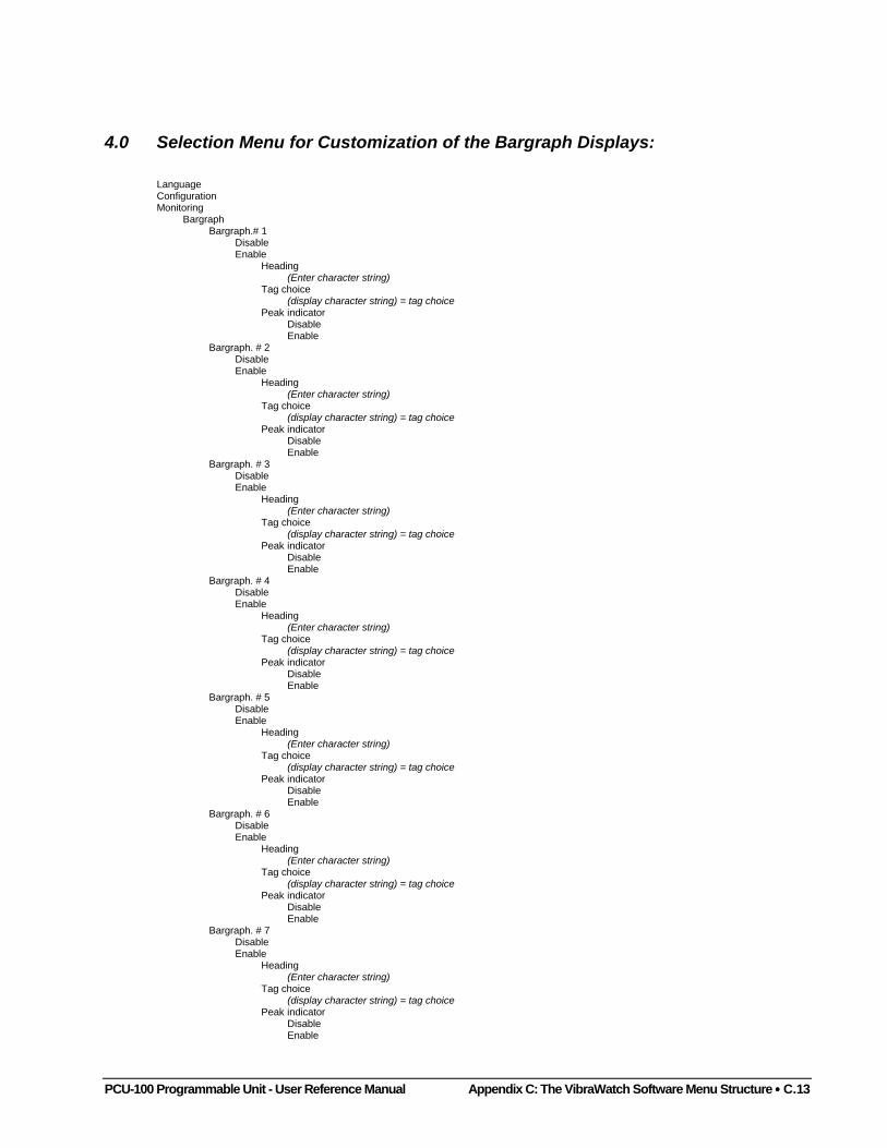
PCU-100 Programmable Unit - User Reference Manual Appendix C: The VibraWatch Software Menu Structure •••• C.13
4.0 Selection Menu for Customization of the Bargraph Displays:
LanguageConfigurationMonitoring
BargraphBargraph.# 1
DisableEnable
Heading(Enter character string)
Tag choice(display character string) = tag choice
Peak indicatorDisableEnable
Bargraph. # 2DisableEnable
Heading(Enter character string)
Tag choice(display character string) = tag choice
Peak indicatorDisableEnable
Bargraph. # 3DisableEnable
Heading(Enter character string)
Tag choice(display character string) = tag choice
Peak indicatorDisableEnable
Bargraph. # 4DisableEnable
Heading(Enter character string)
Tag choice(display character string) = tag choice
Peak indicatorDisableEnable
Bargraph. # 5DisableEnable
Heading(Enter character string)
Tag choice(display character string) = tag choice
Peak indicatorDisableEnable
Bargraph. # 6DisableEnable
Heading(Enter character string)
Tag choice(display character string) = tag choice
Peak indicatorDisableEnable
Bargraph. # 7DisableEnable
Heading(Enter character string)
Tag choice(display character string) = tag choice
Peak indicatorDisableEnable
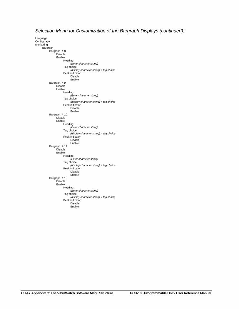
C.14 •••• Appendix C: The VibraWatch Software Menu Structure PCU-100 Programmable Unit - User Reference Manual
Selection Menu for Customization of the Bargraph Displays (continued):LanguageConfigurationMonitoring
BargraphBargraph. # 8
DisableEnable
Heading(Enter character string)
Tag choice(display character string) = tag choice
Peak indicatorDisableEnable
Bargraph. # 9DisableEnable
Heading(Enter character string)
Tag choice(display character string) = tag choice
Peak indicatorDisableEnable
Bargraph. # 10DisableEnable
Heading(Enter character string)
Tag choice(display character string) = tag choice
Peak indicatorDisableEnable
Bargraph. # 11DisableEnable
Heading(Enter character string)
Tag choice(display character string) = tag choice
Peak indicatorDisableEnable
Bargraph. # 12DisableEnable
Heading(Enter character string)
Tag choice(display character string) = tag choice
Peak indicatorDisableEnable
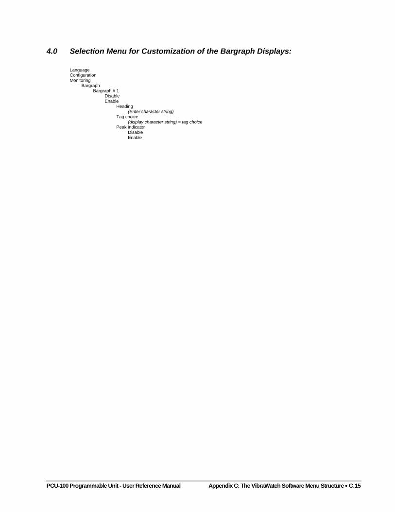
PCU-100 Programmable Unit - User Reference Manual Appendix C: The VibraWatch Software Menu Structure •••• C.15
4.0 Selection Menu for Customization of the Bargraph Displays:
LanguageConfigurationMonitoring
BargraphBargraph.# 1
DisableEnable
Heading(Enter character string)
Tag choice(display character string) = tag choice
Peak indicatorDisableEnable

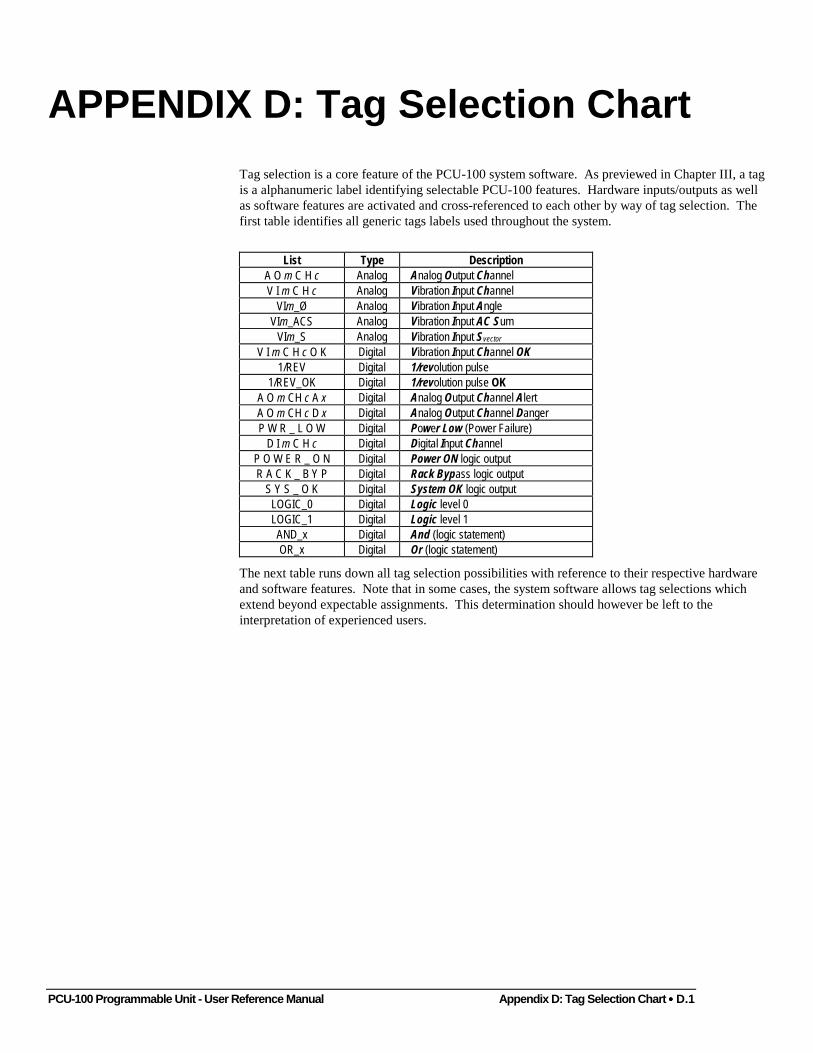
PCU-100 Programmable Unit - User Reference Manual Appendix D: Tag Selection Chart •••• D.1
APPENDIX D: Tag Selection Chart
Tag selection is a core feature of the PCU-100 system software. As previewed in Chapter III, a tagis a alphanumeric label identifying selectable PCU-100 features. Hardware inputs/outputs as wellas software features are activated and cross-referenced to each other by way of tag selection. Thefirst table identifies all generic tags labels used throughout the system.
List Type DescriptionA O m C H c Analog Analog Output ChannelV I m C H c Analog Vibration Input Channel
VIm_Ø Analog Vibration Input AngleVIm_ACS Analog Vibration Input AC Sum
VIm_S Analog Vibration Input Svector
V I m C H c O K Digital Vibration Input Channel OK1/REV Digital 1/revolution pulse
1/REV_OK Digital 1/revolution pulse OKA O m CH c A x Digital Analog Output Channel AlertA O m CH c D x Digital Analog Output Channel DangerP W R _ L O W Digital Power Low (Power Failure)
D I m C H c Digital Digital Input ChannelP O W E R _ O N Digital Power ON logic outputR A C K _ B Y P Digital Rack Bypass logic output
S Y S _ O K Digital System OK logic outputLOGIC_0 Digital Logic level 0LOGIC_1 Digital Logic level 1AND_x Digital And (logic statement)OR_x Digital Or (logic statement)
The next table runs down all tag selection possibilities with reference to their respective hardwareand software features. Note that in some cases, the system software allows tag selections whichextend beyond expectable assignments. This determination should however be left to theinterpretation of experienced users.
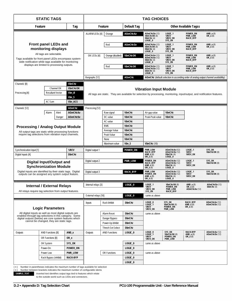
D.2 •••• Appendix D: Tag Selection Chart PCU-100 Programmable Unit - User Reference Manual
STATIC TAGS TAG CHOICES
Feature Tag Feature Default Tag Other Available Tagss
Orange AOmCHcAxALARM LEDs [4] AOmCHcDx (12)VImCHcOK (8)DImCHc (4)LOGIC_0
LOGIC_11/REV1/REV_OKSYS_OK
POWER_ONPWR_LOWRACK_BYP
AND_x (8)OR_x (8)
Red AOmCHcDx AOmCHcAx (12)VImCHcOK (8)DImCHc (4)LOGIC_0
LOGIC_11/REV1/REV_OKSYS_OK
POWER_ONPWR_LOWRACK_BYP
AND_x (8)OR_x (8)
Orange (disabled) VImCHcOKOK LEDs [4] AOmCHcAx (12)AOmCHcDx (12)DImCHc (4)LOGIC_0
LOGIC_11/REV1/REV_OKSYS_OK
POWER_ONPWR_LOWRACK_BYP
AND_x (8)OR_x (8)
Red VImCHcOK AOmCHcAx (12)AOmCHcDx (12)DImCHc (4)LOGIC_0
LOGIC_11/REV1/REV_OKSYS_OK
POWER_ONPWR_LOWRACK_BYP
AND_x (8)OR_x (8)
Front panel LEDs andmonitoring displays
All tags are selectable.
Tags available for front panel LEDs encompass system-wide notification while tags available for monitoring
displays are limited to processing outputs.
Bargraphs [12] AOmCHc AOmCHc (default selection in ascending order of analog output channel availability)
Channelc [8] VImCHcChannel OK VImCHcOK
Resultant Vector VIm_ØVIm_S
Processing [4]
AC Sum VIm_ACS
Vibration Input ModuleAll tags are static. They are available for selection by processing, monitoring, input/output, and notification features.
Channelc [12] AOmCHc Processing [12]
Alarm Alert AOmCHcAx Raw signal VImCHc Air gap value VImCHcDanger AOmCHcDx DC value VImCHc Peak-Peak value VImCHc
AC value VImCHcRMS VImCHcAverage Value VImCHcPeak Value VImCHcNone VImCHc
Processing / Analog Output ModuleAll output tags are static while processing functionsrequire tag selections from vibration input channels.
Maximum value VIm_S VImCHc (10)
Synchronization input [1] 1/REV Digital output 1 POWER_ONDigital inputs [4] DImCHc
PWR_LOWRACK_BYPAND_x (8)OR_x (8)
AOmCHcAx (12)AOmCHcDx (12)DImCHc (4)LOGIC_0
LOGIC_11/REV1/REV_OK
SYS_OKVImCHcOK (8)
Digital output 2 PWR_LOW POWER_ONRACK_BYPAND_x (8)OR_x (8)
AOmCHcAx (12)AOmCHcDx (12)DImCHc (4)LOGIC_0
LOGIC_11/REV1/REV_OK
SYS_OKVImCHcOK (8)
Digital output 3 RACK_BYP
Digital Input/Output andSynchronization Module
Digital inputs are identified by their static tags. Digitaloutputs can be assigned any system output feature.
PWR_LOWPOWER_ONAND_x (8)OR_x (8)
AOmCHcAx (12)AOmCHcDx (12)DImCHc (4)LOGIC_0
LOGIC_11/REV1/REV_OK
SYS_OKVImCHcOK (8)
Internal relays [3] LOGIC_0Internal / External RelaysAll relays require tag selection from output features.
LOGIC_11/REV1/REV_OKSYS_OK
VImCHcOK (8)POWER_ONPWR_LOWRACK_BYP
AND_x (8)OR_x (8)AOmCHcAx (12)
AOmCHcDx (12)DImCHc (4)
External relays [18] LOGIC_0 same as above
Inputs Rack Inhibit DImCHc LOGIC_0LOGIC_11/REV1/REV_OK
SYS_OKVImCHcOK (8)POWER_ONPWR_LOW
RACK_BYPAND_x (8)OR_x (8)
AOmCHcAx (12)AOmCHcDx (12)
Alarm Reset DImCHc
Danger Bypass DImCHc
Power-Up Inhibit DImCHc
Logic ParametersAll digital inputs as well as most digital outputs are
enabled through tag selections in this category. Somedigital outputs (below) are core system features which
cannot be changed, they are static tags.
Thresh Set Select DImCHc
same as above
Outputs AND Functions [8] AND_x Outputs AND Functions LOGIC_0
OR Functions [8] OR_x
LOGIC_0LOGIC_11/REV1/REV_OK
SYS_OKVImCHcOK (8)POWER_ONPWR_LOW
RACK-BYPAND_x (8)OR_x (8)
AOmCHcAx (12)AOmCHcDx (12)
OK System SYS_OK LOGIC_0
Power-On POWER_ON LOGIC_0
same as above
Power Low PWR_LOW OR Functions LOGIC_0
Rack Bypass (inhibit) RACK-BYP LOGIC_0
LOGIC_0
same as above
( n ) Number in parentheses indicates the maximum number of tags available for selection[ n ] Number between brackets indicates the maximum number of configurable idems
SAMPLE_TEXT Inverted text identifies output tags tied to features which relateto the outside world such as LEDs and connectors.
PCU-100 Programmable Unit - User Reference Manual Index
Index
1
1/rev pulse, 2.28configuration, 3.57
A
AC coupling, 3.36, B.1AC sum, 3.38AC value, B.2
process configuration, 3.42Access code, 3.24, 3.26Accessing the menu, 2.4, 3.3Acetone, 2.36Acknowledging alarms, 2.3, 3.16Active level
digital inputs, 3.56digital outputs, 3.57
Air gapminimum value, 3.48parameter protection, 2.28
Airgap value, B.2bargraph display, 3.47process configuration, 3.47range of detection, 3.50, 3.52
Alarmconfiguration
processing and analog output channel, 3.48device switching, 2.20increasing or decreasing?, 2.19LEDs, 2.3, 2.20
color coding, 2.3voting logic, 2.3
not valid, 2.19protected parameters, 2.3reset, 2.30
configuration, 3.64threshold, 2.17, 2.20, 3.14
alert, 2.20danger, 2.20viewing, 2.20, 3.15
type, 3.53validation, 2.4, 3.24
Alert thresholdenabling, 3.27
Alphanumericdisplay, 2.3, 3.2entry, 3.11
character set, 3.12Analog outputs
selection, 3.39AND function, 3.62Angle
(Ø) value, 3.38reading, 2.28
API 670 standard, 2.30Auxiliary output
connectorsBNC, 2.5
voltage, 2.5Average value, B.2
process configuration, 3.43
B
Bargraph display, 3.14acknowledging an alarm, 3.16configuration, 3.67header, 3.15peak indicator, 3.14pixel, 3.16threshold indicator, 3.14
BNC connectors, 2.5, 2.11wiring, 2.12
Bolts 5/16-16 × 1/2’’, 2.35Boot-up sequence, 1.3, 3.24Brightness, 3.26Bus, 2.8
C
Cablessynchronization, 2.35
direction, 2.34Cancel button, 3.4Channel OK, 3.37Character set, 3.9, 3.12Checksum, 3.30Circuit board, 2.2Communication
cable, 2.42connector, 2.42option, 2.6port, 2.6, 2.40RS-485 address setting, 3.31
ConfigurationBARGRAPH DISPLAYS, A.7DIGITAL I/O AND SYNCHRONIZATION MODULE, A.4,
C.7digital input/output and synchronization module, 3.55external relay card unit, 3.58, A.6, C.9general system parameters, 3.24, A.1, C.1
Index PCU-100 Programmable Unit - User Reference Manual
internal relay module, 3.58, A.5, C.8logic parameters, 3.62menu, 3.32monitoring displays, 3.67processing and analog output module, 3.39, A.3, C.5saving, 3.17vibration input module, 3.32, A.2, C.3
Configuration filename, 3.21, 3.25CPU, 2.8Crimp contacts, 2.12Cursor position, 2.3
D
Dangerbypass, 2.30
configuration, 3.64threshold
enabling, 3.27Date
format, 3.5setting, 3.5, 3.24, 3.25
DC value, B.2process configuration, 3.42
Decay timeAirgap value, 3.48Maximum value, 3.47Peak value, 3.45Peak-to-peak value, 3.48RMS, 3.45
Decimal fixprocessing and analog output channel, 3.54
Decreasing values, 3.53Digital
inputs, 2.30, 2.32configuration, 3.56
outputs, 2.32configuration, 3.56
Digital I/O and synchronization module, 3.55definition, 2.7installation, 2.32selection, 3.55specifications, 4.2wiring, 2.33
Displaymessages, 3.21type, 2.3
DPDT, 2.23diagram, 2.24
DPST diagram, 2.21DSP
digital data processing, 1.2
E
Eject lever, 2.5Expansion bay, 2.2, 2.5External relay card unit, 3.58
definition, 2.7LED, 2.23selection, 3.60specifications, 4.2
External vibration meter, 2.11
F
Filler gage, 2.37Firmware
update, 3.19version, 3.24
Fish-tape, 2.34FOA-100 accelerometer power supply, 2.12Front panel, 2.2
G
General system parameters, 3.24Generator shaft, 2.35Gluing the synchronization target, 2.36Grounding, 2.38
H
Handling tips, 1.3Heading
bargraph configuration, 3.68High-limit
processing and analog output channel, 3.54High-pass filter
AC value, 3.42Peak value, 3.45Peak-to-peak value, 3.48RMS, 3.44
Hysteresisalarms, 3.50, 3.52
I
I/O Ports, 2.6ICRS-485 communication interface, 2.6
communication port, 2.6specifications, 4.3
Increasing values, 3.53Input logic parameters, 3.63Input range (setting the), 3.33Installation
Digital I/O and synchronization module, 2.32internal relay driver module with relay card, 2.25
PCU-100 Programmable Unit - User Reference Manual Index
internal relay module, 2.22processing and analog output module, 2.18vibration input module, 2.11
Instrumentation, 2.5Internal relay driver module with relay card, 2.23
installation, 2.25wiring, 2.26
Internal relay module, 2.21, 3.58definition, 2.7installation, 2.22selection, 3.58specifications, 4.2wiring, 2.22
K
Keypad, 3.1Cancel button, 2.4down arrow button, 2.3Enter button, 2.3layout, 2.2left arrow button, 2.3Menu button, 2.4right arrow button, 2.3test mode, 2.3, 2.4up arrow button, 2.3
L
Languagedefault selection, 3.24selecting, 3.24
Latching, 3.50LEDs, 3.27
Alarm, 2.3color coding, 2.3, 2.4communication interface, 2.41configuration, 3.27enabling, 3.24external relay card unit status, 2.23PCMCIA activity, 2.5power indicator, 2.5, 2.6Status OK, 2.4, 3.24Status OK incompatibilities, 2.15
Left and Right arrow buttonmonitoring mode, 2.3
Limit settingvibration input channel, 3.34
Lock washers, 2.35Logic parameters, 3.62
selection, 3.63Low limit
processing and analog output channel, 3.53Low-pass filter
AC value, 3.43DC value, 3.42raw signal, 3.41
M
Machine startup, 2.31Main power connector, 2.38Master-slave operation, 2.31Maximum value, B.2
process configuration, 3.46Menu
Cancel, 2.4Enter, 2.3Menu button, 2.4paths, C.1
Mix and matchtask modules, 2.8
Monitoringacknowledging alarms, 2.3displays, 3.67selection, 3.67
Monitran accelerometers and status OK, 2.19
N
None, no processing, 3.46, B.2Normal state
internal relay, 3.59Normally closed, 2.24Normally open, 2.24Numeric entry
character set, 3.9scientific notation, 3.9
O
OK LEDsenabling, 3.28
OK Systemconfiguration, 3.64
Option pointer, 3.3OR function, 3.62Oscilloscope, 2.28Output logic parameters, 3.64
P
Parts and Controls, 2.2PCMCIA
activity LED, 2.5card slots, 2.5, 4.3jumpers, 2.6saving configuration, 3.17
Index PCU-100 Programmable Unit - User Reference Manual
updating configuration, 3.18updating system software, 3.19
PCS sensor, 2.28linearized signal, 2.11measuring chain, 2.11
PCUconnectivity, 2.8CPU, 2.8features, 1.2highlights, 1.1keypad, 3.1on-line protection, 2.21
Peak indicatorbargraph configuration, 3.68
Peak value, B.2process configuration, 3.45
Peak-to-peak value, B.2process configuration, 3.48
Power LED, 2.5, 2.6Power low
configuration, 3.64Power station configuration, 2.41Power supply, 2.2, 2.38
AC to DC conversion, 2.38connection to main, 2.6DC to DC conversion, 2.38grounding, 2.38input from main, 2.5input requirements, 2.38protection fuses, 2.6rating, 2.5specifications, 4.4
Power switch, 2.6Power-on
configuration, 3.64Power-up inhibit, 2.30
configuration, 3.64Process
AC value, B.2airgap value, B.2average value, B.2DC value, B.2maximum value, B.2none, B.2peak value, B.2peak-to-peak value, B.2raw signal, B.2RMS value, B.2
Process validationStatus OK LED, 2.20
Processing and analog output module, 2.16, 3.39definition, 2.7installation, 2.18processes, 2.17
signal source, 2.16specifications, 4.1wiring, 2.18
Prompts, 3.17, 3.18, 3.21Protection fuses
rating, 2.6Protective conduits, 2.34
R
Rack bypassconfiguration, 3.64
Rack inhibit, 2.30logic parameter configuration, 3.63
Raw signal, 2.11, B.2process configuration, 3.41
Rear panel, 2.2communication port, 2.6I/O ports, 2.6main power connector, 2.6power switch, 2.6protection fuses, 2.6
Relaycard unit, 2.24configuration, 3.59, 3.60normally closed, 2.21normally open, 2.21protection, 2.20
Restoring configuration, 3.18Resultant vector, 3.38Rise time
airgap value, 3.47maximum value, 3.47Peak value, 3.45Peak-to-peak value, 3.48RMS, 3.45
RMS value, B.2process configuration, 3.44
S
Safeguard against false alarms, 2.17Safety, 1.3
static electricity buildup, 2.11Sampling rate, 1.2Saving configuration, 3.17, 3.30Scroll
arrow buttons, 3.3pointers, 3.3through character sets, 2.3
Sensoroffset, 3.36wiring, 2.12
Shaft, 2.36
PCU-100 Programmable Unit - User Reference Manual Index
displacement monitoring, 2.27Smax, 2.17, 2.28Software
RS-485 address setting via, 3.31structure, C.1version number, 2.40
Specifications, 4.1Static tag, 3.27
1/rev pulse, 3.57digital inputs, 3.56processing and analog output channel, 3.40
Status OK, 2.17LEDs, 2.4, 2.20, 3.24
color coding, 2.4exceptions, 2.19voting logic, 2.4
measuring chain validation, 2.4, 3.24Status parameters
inputs, 2.41Straps, 2.36Svector, 3.38Synchronization
signal, 2.28theory, 2.29
Synchronization probeadjustment, 2.36cable, 2.34fastening, 2.35installation, 2.34special support, 2.35specifications, 4.2
System hardwareupgrade, 2.8
System softwareupdate, 3.19
System unitprocessing and analog output channel, 3.54
T
Tag choiceAC value, 3.42airgap value, 3.47alarms, 3.49average value, 3.43bargraph, 3.68DC value, 3.42digital outputs, 3.57external relay, 3.60internal relay, 3.59logic parameter, 3.64maximum value, 3.46none, 3.46peak value, 3.45
peak-to-peak value, 3.48raw signal, 3.41RMS, 3.44
Tag Selection Chart, D.1Tags, 3.13
types, 3.13Target
detection, 2.34installation, 2.36
Task module, 2.7, 4.1address DIP switch, 2.8assignment, 3.31basic requirements, 2.8digital input, 2.32digital output, 2.32displaying assignment, 3.22expansion bay, 2.5mix and match, 2.8selection, 3.32
Terminal assignmentFOA-100 optoelectronic accelerometer with built-in
conditioner, 2.13PCS sensor, 2.13synchronization probe, 2.34velocity transducer with bloc conditioner, 2.14VM3.12, VM3.2 and VM5.0 with bloc conditioner,
2.15Wilcoxon 797L accelerometer, 2.14Wilcoxon 797V velocimeter, 2.15
Termination resistance, 2.40Test mode, 2.3, 2.4Third party sensors, 2.12Threshold
alarms, 3.49levels, 2.3set selection, 2.31, 3.49, 3.51
Timeformat, 3.7setting, 3.7, 3.24, 3.26
Time constantAverage value, 3.44
Time delayalarms, 3.50, 3.52
Transitory periods of the monitored machine, 2.31Tree diagram, 3.2Types of PCMCIA cards, 2.4, 4.3
U
Up and Down arrow buttonmonitoring mode, 2.3
Updatingfirmware, 3.31
Updating configuration, 3.18, 3.30
Index PCU-100 Programmable Unit - User Reference Manual
Upgradingexternal relay card unit, 2.25firmware, 2.40internal relay module, 2.22processing and analog output module, 2.18vibration input module, 2.11
Upstream, 2.34User interface, 3.1
alphanumeric entry, 3.11bargraph display, 3.14decimal point, 3.9menu structure, 3.2numeric entry, 3.9selecting a Tag, 3.13selecting an option, 3.4
V
Validation of the measuring chain, 2.4, 3.24Version number, 3.24, 3.31VFD screen, 3.2Vibration input channel
status OK bargraph header, 3.16Vibration input module, 3.32, B.1
AC coupling, 3.36accelerometer transducer, 2.10Channel OK, 3.37configuration, 3.33definition, 2.7displacement sensor, 2.10Eddy current probe, 2.10FOA-100 fiber-optic accelerometer, 2.10frequency low-pass filter, 3.36high limit setting, 3.35
input range, 2.10setting, 3.33
installation, 2.11low limit setting, 3.34offset, 3.36relative vibration sensor, 2.10sampling rate, 2.10specifications, 4.1velocity transducer, 2.10wiring, 2.12
Vibration signal acquisition, 2.10Virtual channels, 3.46Voting logic, 2.3, 2.4, 3.27, 3.62
W
Watchdog, 1.3Wilcoxon Research accelerometers and velocity
transducers vs status OK, 2.19Wiring
Digital I/O and synchronization module, 2.33input module, 2.12internal relay driver and relay card, 2.26internal relay module, 2.22processing and analog output module, 2.18
Z
ZOOM ConfigurationStatus parameter inputs, 2.17
ZOOM monitoring system, 2.6, 2.7, 2.39communication network, 2.39power station configuration, 2.17