Embed Size (px)
Citation preview
PCV Line Oil Removal 102: The Sequel
Note: For those who missed PCV Line Oil Removal 101, I am including a recap of
PCV operation descriptions.
Having been involved the utilization of compressed air systems and related components
for many years, I became interested in the proliferation of “Oil Catch Cans” in many
different types of vehicles. Could there be a better way to trap oil than the tried and true
methods I’ve grown to know all these years? Let’s take a look at what is going on in that
little PCV tube.
From Wikipedia, we learn that…..
“As an engine runs, the crankcase (containing the crankshaft and other parts) begins to
collect combustion chamber gases that leak past the seals around the pistons. These
combustion gases are sometimes referred to as "blow by" because the combustion
pressure "blows" them "by" the pistons. These gases contain compounds harmful to an
engine, particularly hydrocarbons, which are just unburned fuel. It also contains a
significant amount of water vapor. If allowed to remain in the crankcase, or become too
concentrated, the harmful compounds begin to condense out of the air within the
crankcase and form sludge on the engine's interior surfaces. This can harm the engine as
it tends to clog small inner passages, causing overheating, poor lubrication, and high
emissions levels. To keep the crankcase air as clean as possible, some sort of ventilation
system must be present.
The PCV valve is only one part of the PCV system, which is essentially a closed-loop
calibrated air leak, whereby the engine returns its crankcase combustion gases. Instead of
the gases being vented to the atmosphere, gases are fed back into the intake manifold, to
re-enter the combustion chamber as part of a fresh charge of air and fuel. The PCV
system is not a classical "vacuum leak." Remember that all the air collected by the air
cleaner (and metered by the mass air flow sensor, on a fuel injected engine) goes through
the intake manifold anyway. The PCV system just diverts a small percentage of this air
via the breather to the crankcase before allowing it to be drawn back in to the intake tract
again.
The system relies on the fact that the intake manifold's air pressure is usually less than
crankcase air pressure. The lower pressure of the manifold forces air to flow towards it,
pulling air from the breather, through the crankcase (where it dilutes and mixes with
combustion gases), through the PCV valve, and into the intake manifold.
The PCV system consists of: 1) The breather tube , and 2) The PCV valve. The breather
tube connects the crankcase to a clean source of fresh air, such as the air cleaner body.
Usually, clean air from the air cleaner flows in to this tube and in to the engine after
passing through a screen, baffle, or other simple system to arrest a flame front, to prevent
a potentially explosive atmosphere within the engine crank case from being ignited from
a backfire in to the intake manifold. The baffle, filter, or screen also traps oil mist, and
keeps it inside the engine.
Once inside the engine, the air circulates around the interior of the engine, picking up and
clearing away combustion byproduct gases, including a large amount of water vapor, then
exits through a simple baffle, screen or mesh to trap oil droplets before being drawn out
PCV Line Oil Removal 102 (continued)
Page 2 of 18
through the PCV valve.” Mmmmm – obviously in many engines, this “trap” is not
enough to catch ALL the oil droplets.
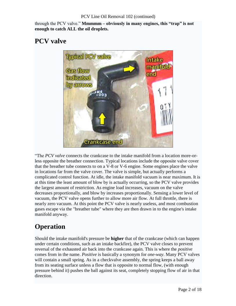
PCV valve
“The PCV valve connects the crankcase to the intake manifold from a location more-or-
less opposite the breather connection. Typical locations include the opposite valve cover
that the breather tube connects to on a V-8 or V-6 engine. Some engines place the valve
in locations far from the valve cover. The valve is simple, but actually performs a
complicated control function. At idle, the intake manifold vacuum is near maximum. It is
at this time the least amount of blow by is actually occurring, so the PCV valve provides
the largest amount of restriction. As engine load increases, vacuum on the valve
decreases proportionally, and blow by increases proportionally. Sensing a lower level of
vacuum, the PCV valve opens further to allow more air flow. At full throttle, there is
nearly zero vacuum. At this point the PCV valve is nearly useless, and most combustion
gases escape via the "breather tube" where they are then drawn in to the engine's intake
manifold anyway.
Operation
Should the intake manifold's pressure be higher that of the crankcase (which can happen
under certain conditions, such as an intake backfire), the PCV valve closes to prevent
reversal of the exhausted air back into the crankcase again. This is where the positive
comes from in the name. Positive is basically a synonym for one-way. Many PCV valves
will contain a small spring. As in a checkvalve assembly, the spring keeps a ball away
from its seating surface unless a flow that is opposite to normal flow, (with enough
pressure behind it) pushes the ball against its seat, completely stopping flow of air in that
direction.
PCV Line Oil Removal 102 (continued)
Page 3 of 18
It is critical that the parts of the PCV system be kept clean and open, otherwise air flow
will not be correct. A plugged or malfunctioning PCV system will eventually damage
an engine. PCV problems are primarily due to neglect or poor maintenance,
typically engine oil change intervals that are inadequate for the engine's driving
conditions. A poorly-maintained engine's PCV system will eventually become
contaminated with sludge, causing serious problems. If the engine's lubricating oil is
changed with adequate frequency, the PCV system will remain clear practically for
the life of the engine. However, since the valve is constantly changing its resistance to
flow by opening and closing proportionally as one drives a car, it is subject to eventual
wear out over time. Typical maintenance schedules for gasoline engines are to replace the
PVC valve whenever spark plugs are replaced. The long life of the valve despite the
harsh operating environment is due to the trace amount of oil droplets suspended in the
air that flows through the valve. These droplets keep the valve lubricated. This means
that you probably shouldn’t remove all oil before the PCV valve and fortunately,
most oil catch cans are placed in-line after the PCV valve.
Not all gasoline engines have PCV valves. Engines not subject to emission controls, such
as certain off-road engines, retain road draft tubes. Dragsters use a scavenger system and
venturi tube in the exhaust to draw out combustion gases and maintain a small amount of
vacuum in the crankcase to prevent oil leaks on to the race track. Small gasoline 2-cycle
engines use the crank case to compress incoming air. All blow by in these engines is
burned in the regular flow of air and fuel through the engine. Many small 4-cycle engines
such as lawn mower engines and small gasoline generators, simply use a draft tube
connected to the intake, between the air filter and carburetor, to route all blow by back in
to the intake combustion air. The higher operating temperature of these small engines has
a side effect of preventing large amounts of water vapor and light hydrocarbons from
condensing in the lube oil.”
For some good images of PCV systems, see http://www.autoshop101.com/forms/h63.pdf
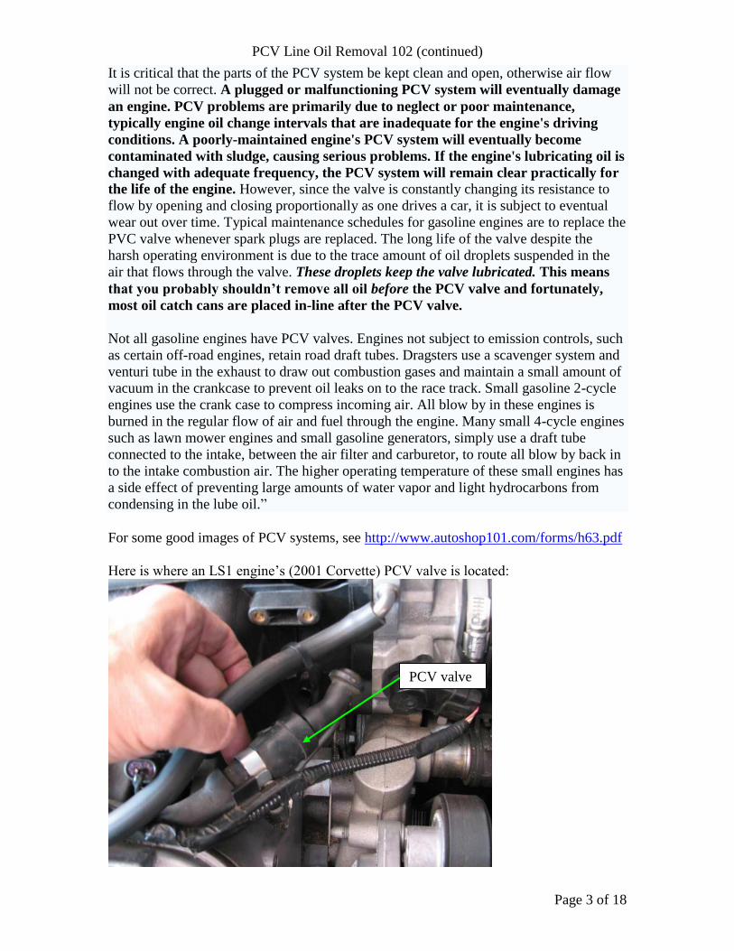
Here is where an LS1 engine’s (2001 Corvette) PCV valve is located:
PCV valve
PCV Line Oil Removal 102 (continued)
Page 4 of 18
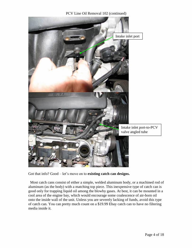
Got that info? Good – let’s move on to existing catch can designs.
Most catch cans consist of either a simple, welded aluminum body, or a machined rod of
aluminum (as the body) with a matching top piece. This inexpensive type of catch can is
good only for trapping liquid oil among the blowby gases. At best, it can be mounted in a
cool area of the engine bay, which would encourage some coalescence of air-born oil
onto the inside wall of the unit. Unless you are severely lacking of funds, avoid this type
of catch can. You can pretty much count on a $19.99 Ebay catch can to have no filtering
media inside it.
Intake inlet port
Intake inlet port-to-PCV
valve angled tube
PCV Line Oil Removal 102 (continued)
Page 5 of 18
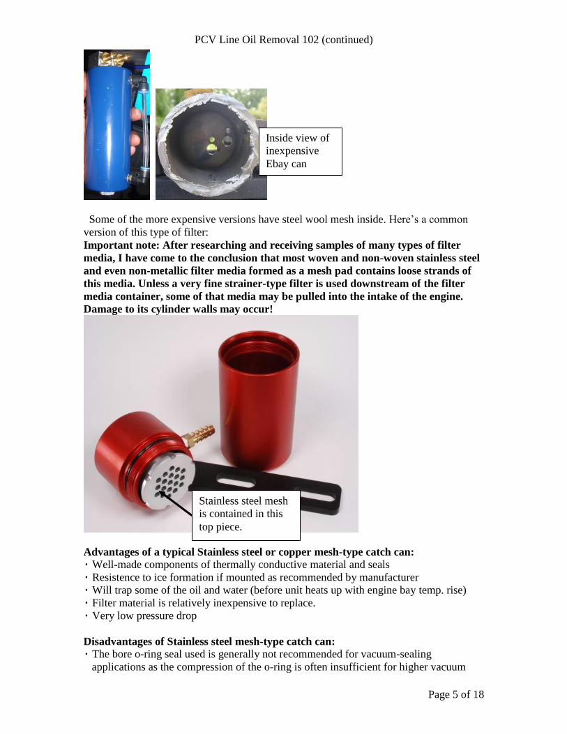
Some of the more expensive versions have steel wool mesh inside. Here’s a common
version of this type of filter:
Important note: After researching and receiving samples of many types of filter
media, I have come to the conclusion that most woven and non-woven stainless steel
and even non-metallic filter media formed as a mesh pad contains loose strands of
this media. Unless a very fine strainer-type filter is used downstream of the filter
media container, some of that media may be pulled into the intake of the engine.
Damage to its cylinder walls may occur!
Advantages of a typical Stainless steel or copper mesh-type catch can:
٠ Well-made components of thermally conductive material and seals
٠ Resistence to ice formation if mounted as recommended by manufacturer
٠ Will trap some of the oil and water (before unit heats up with engine bay temp. rise)
٠ Filter material is relatively inexpensive to replace.
٠ Very low pressure drop
Disadvantages of Stainless steel mesh-type catch can:
٠ The bore o-ring seal used is generally not recommended for vacuum-sealing
applications as the compression of the o-ring is often insufficient for higher vacuum
Stainless steel mesh
is contained in this
top piece.
Inside view of
inexpensive
Ebay can

PCV Line Oil Removal 102 (continued)
Page 6 of 18
pressure conditions. Leaks could allow unfiltered air to be pulled into the intake
manifold.
٠ Strands of media may be pulled away from mesh pad and enter the engine’s intake
manifold, potentially causing damage to cylinder walls and/or valves.
٠ Location recommended by manufacturer not best to coalesce water and oil (mounting
unit to engine with thermally-conductive bracket will transmit heat to unit. As a rule of
thumb, the higher the temperature of the filter media, the greater the percentage of oil
aerosols that will get past the media and end up in your intake.
٠ High cost of unit
٠ Velocity of gasses may be insufficient for adequate impaction of oil droplets against
mesh material. The large diameter of filter media contributes to this reduced velocity.
٠ Direction of air flow exposes air exiting filter to liquid oil.
٠ Entrapped oil/water is not visible to user.
٠ Paticulates and smaller-sized oil aerosols in blowby gases may easily get past the very
medium-course filter media
٠ Large quantity of trapped oil can slosh around when subjected to rapid oscillations due
to rough roads and high vehicle speeds. Some of this oil may become airbore and be
pulled out (retrained from the oil) of the can and sent to the intake manifold.
Non-metallic filter media catch cans:
This type of filter media has an upper temperature limit that is almost certainly lower
than that of the stainless steel media, so if you have this type of catch can, ask the
vendor what the media temperature limit is. Keep this in mind when mounting the unit.
Advantages of a typical non-metallic mesh-type catch can:
٠ Well-made components of thermally-conductive material (except filter media)
٠ Resistence to ice formation if mounted as recommended by manufacturer
٠ Will trap some of the oil and water (before unit heats up with engine bay temp. rise)
٠ Filter material is relatively inexpensive to replace.
٠ Very low pressure drop
Disadvantages of non-metallic mesh-type catch can:
٠ The bore o-ring seal used is generally not recommended for vacuum-sealing
applications as the compression of the o-ring is often insufficient for higher vacuum
pressure conditions. Leaks could allow unfiltered air to be pulled into the intake

PCV Line Oil Removal 102 (continued)
Page 7 of 18
manifold. Compared to the metallic-filter catch’s o-ring can shown previously, this o-
ring’s cross-section is larger – an advantage but still not ideal.
٠ Location recommended by manufacturer not best to coalesce water and oil (mounting
unit to engine with thermally-conductive bracket will transmit heat to unit. As a rule of
thumb, the higher the temperature of the filter media, the greater the percentage of oil
aerosols that will get past the media and end up in your intake.
٠ Direction of air flow exposes air exiting filter to liquid oil.
٠ Entrapped oil/water is not visible to user.
٠ Paticulates and smaller-sized airborn oil in blowby gases may easily get past the
medium-course filter media
٠ Large quantity of trapped oil can slosh around when subjected to rapid oscillations due
to rough roads and high vehicle speeds. Some of this oil may become airbore and be
pulled out (retrained from the oil) of the can and sent to the intake manifold.
Another variation of the above…..
Unlike the previous two catch can designs, this one features a face o-ring seal, which
is preferred for vacuum pressure sealing. However, the filter media diameter is large
enough so that blowby gas velocity may be insufficient to allow adequate impaction of
oil droplets against the media. The outer body is a full 2.5 inches in diameter, which
can make it a bit tricky to mount in tight places.
Another interesting feature is the inner wall surface. Grooves are cut into the wall to
discourage oil climbing. My guess is that the direction of the gas flow path is such that
the air travels downward through the media, exposing itself to the liquid oil that is
traveling in the same direction. The air then travels in between the inner and outer
pieces. This is another setup that will trap bulk liquids and some of the mid-to-larger
droplets, but much of the smaller droplets common to crankcase blowby gasses will
escape.
PCV Line Oil Removal 102 (continued)
Page 8 of 18
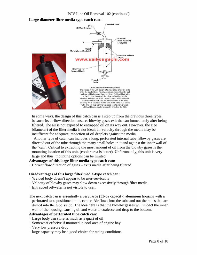
Large diameter filter media-type catch cans
In some ways, the design of this catch can is a step up from the previous three types
because its airflow direction ensures blowby gases exit the can immediately after being
filtered. The air is not exposed to entrapped oil on its way out. However, the size
(diameter) of the filter media is not ideal; air velocity through the media may be
insufficent for adequate impaction of oil droplets against the media.
Another type of catch can includes a long, perforated internal tube. Blowby gases are
directed out of the tube through the many small holes in it and against the inner wall of
the “can”. Critical to extracting the most amount of oil from the blowby gases is the
mounting location of this unit. (cooler area is better). Unfortunately, this unit is very
large and thus, mounting options can be limited.
Advantages of this large filter media-type catch can:
٠ Correct flow direction of gases – exits media after being filtered
Disadvantages of this large filter media-type catch can:
٠ Welded body doesn’t appear to be user-servicable
٠ Velocity of blowby gases may slow down excessively through filter media
٠ Entrapped oil/water is not visible to user.
The next catch can is essentially a very large (32-oz capacity) aluminum housing with a
perforated tube positioned in its center. Air flows into the tube and out the holes that are
drilled into the tube’s side. The idea here is that the blowby gasses will impact the inner
wall of the housing, causing oil and water to coalesce and drop to the bottom.
Advantages of perforated tube catch can:
٠ Large body can store as much as a quart of oil
٠ Somewhat effecive if mounted in cool area of engine bay
٠ Very low pressure drop
٠ large capacity may be a good choice for racing conditions.
PCV Line Oil Removal 102 (continued)
Page 9 of 18
Disadvantages of perforated catch can:
٠ Large quantity of trapped oil can slosh around when subjected to rapid oscillations due
to rough roads and high vehicle speeds. Some of this oil may become airbore and
pulled out of the can to the intake manifold.
٠ Entrapped oil/water is not visible to user
٠ Paticulates in blowby gases are not trapped and will pass through to intake
٠ Entrapped oil/water is not visible to user.
Okay, what else is there? A thorough search of oil/water separators brought up an
interesting invention – the multi-twister separator by Dana Corporation. From their
website…..
Dr. Dieter Grafl, manager of a physical and chemical laboratory for Dana Corp., says,
"Blow-by contains approximately 60% water, along with other components including air,
oil, soot, wear debris and dust. Any process involved with cleaning this stream must take
into account the high concentration of water."
Blow-by gas emissions can represent up to 25% of total vehicular emissions. New
technology that can reduce this source of vehicular emissions will help OEMs meet more
stringent regulations.
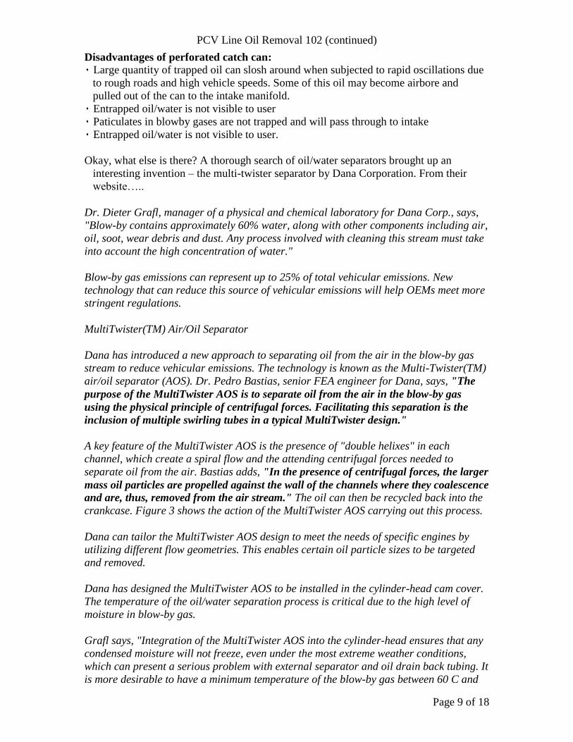
MultiTwister(TM) Air/Oil Separator
Dana has introduced a new approach to separating oil from the air in the blow-by gas
stream to reduce vehicular emissions. The technology is known as the Multi-Twister(TM)
air/oil separator (AOS). Dr. Pedro Bastias, senior FEA engineer for Dana, says, "The
purpose of the MultiTwister AOS is to separate oil from the air in the blow-by gas
using the physical principle of centrifugal forces. Facilitating this separation is the
inclusion of multiple swirling tubes in a typical MultiTwister design."
A key feature of the MultiTwister AOS is the presence of "double helixes" in each
channel, which create a spiral flow and the attending centrifugal forces needed to
separate oil from the air. Bastias adds, "In the presence of centrifugal forces, the larger
mass oil particles are propelled against the wall of the channels where they coalescence
and are, thus, removed from the air stream." The oil can then be recycled back into the
crankcase. Figure 3 shows the action of the MultiTwister AOS carrying out this process.
Dana can tailor the MultiTwister AOS design to meet the needs of specific engines by
utilizing different flow geometries. This enables certain oil particle sizes to be targeted
and removed.
Dana has designed the MultiTwister AOS to be installed in the cylinder-head cam cover.
The temperature of the oil/water separation process is critical due to the high level of
moisture in blow-by gas.
Grafl says, "Integration of the MultiTwister AOS into the cylinder-head ensures that any
condensed moisture will not freeze, even under the most extreme weather conditions,
which can present a serious problem with external separator and oil drain back tubing. It
is more desirable to have a minimum temperature of the blow-by gas between 60 C and
PCV Line Oil Removal 102 (continued)
Page 10 of 18
70 C. This avoids condensation of the moisture, which accumulates in the sump and can
present a problem for the engine oil pump."
Ah, finally, some specifics about how oil can be removed from blowby gasses
without requiring a filter. Unfortunately, very small oil droplets in the blowby gasses
are free to exit the cam cover and be pulled into the intake. Still, one can only wonder
how particulates and water, both of which are contained in blowby gasses, are disposed
of. Most likely, they are directed to the crankcase in the hope that the oil filter will
eventually catch them. Now, we can’t go out and buy a Dana catch can, so what can we
buy to “spin off” blowby gasses against a surface to coalesce oil onto it? Read on…
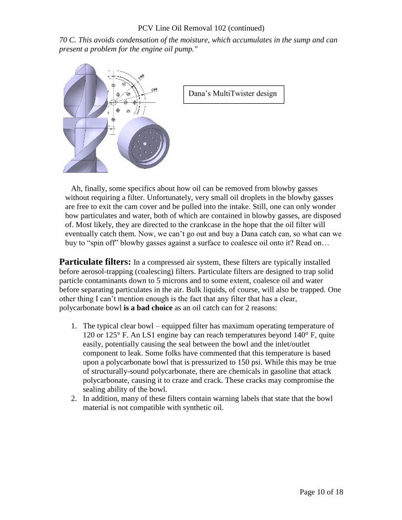
Particulate filters: In a compressed air system, these filters are typically installed
before aerosol-trapping (coalescing) filters. Particulate filters are designed to trap solid
particle contaminants down to 5 microns and to some extent, coalesce oil and water
before separating particulates in the air. Bulk liquids, of course, will also be trapped. One
other thing I can’t mention enough is the fact that any filter that has a clear,
polycarbonate bowl is a bad choice as an oil catch can for 2 reasons:
1. The typical clear bowl – equipped filter has maximum operating temperature of
120 or 125° F. An LS1 engine bay can reach temperatures beyond 140° F, quite
easily, potentially causing the seal between the bowl and the inlet/outlet
component to leak. Some folks have commented that this temperature is based
upon a polycarbonate bowl that is pressurized to 150 psi. While this may be true
of structurally-sound polycarbonate, there are chemicals in gasoline that attack
polycarbonate, causing it to craze and crack. These cracks may compromise the
sealing ability of the bowl.
2. In addition, many of these filters contain warning labels that state that the bowl
material is not compatible with synthetic oil.
Dana’s MultiTwister design
PCV Line Oil Removal 102 (continued)
Page 11 of 18
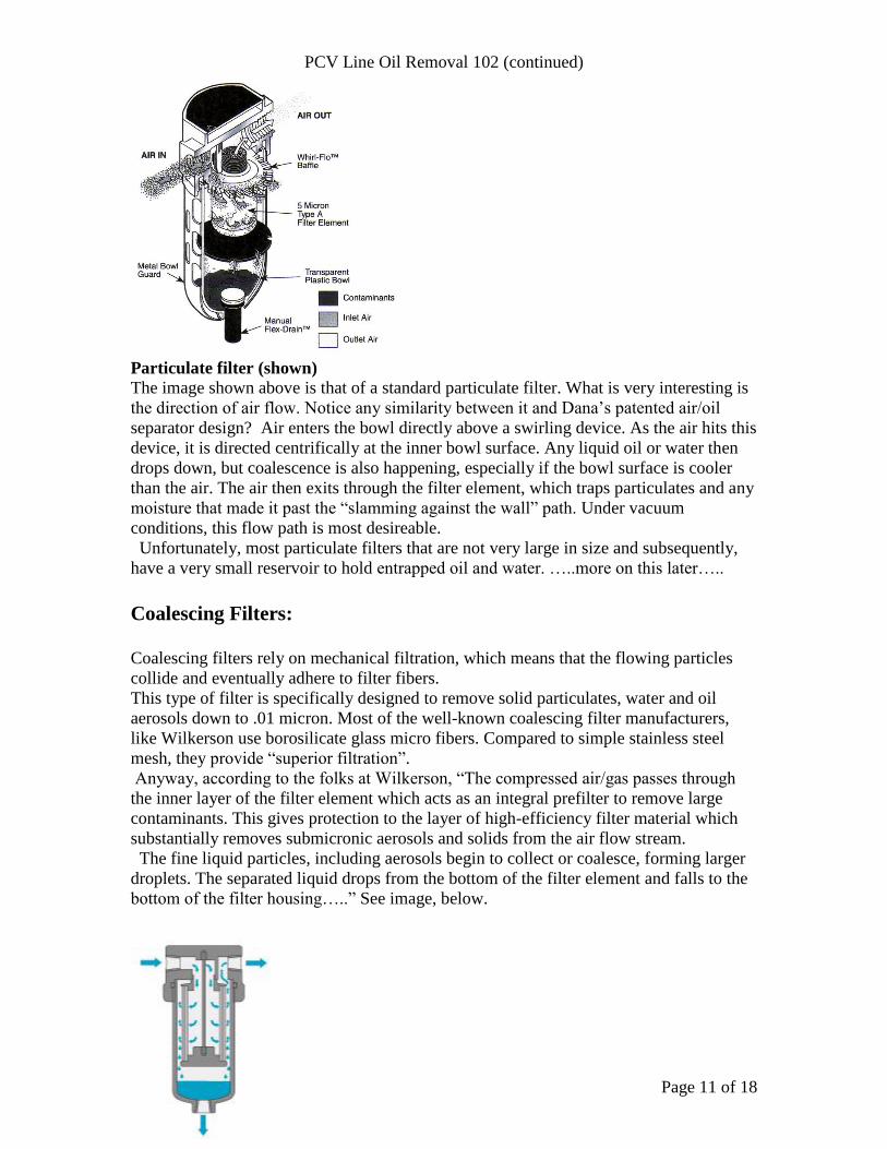
Particulate filter (shown)
The image shown above is that of a standard particulate filter. What is very interesting is
the direction of air flow. Notice any similarity between it and Dana’s patented air/oil
separator design? Air enters the bowl directly above a swirling device. As the air hits this
device, it is directed centrifically at the inner bowl surface. Any liquid oil or water then
drops down, but coalescence is also happening, especially if the bowl surface is cooler
than the air. The air then exits through the filter element, which traps particulates and any
moisture that made it past the “slamming against the wall” path. Under vacuum
conditions, this flow path is most desireable.
Unfortunately, most particulate filters that are not very large in size and subsequently,
have a very small reservoir to hold entrapped oil and water. …..more on this later…..
Coalescing Filters:
Coalescing filters rely on mechanical filtration, which means that the flowing particles
collide and eventually adhere to filter fibers.
This type of filter is specifically designed to remove solid particulates, water and oil
aerosols down to .01 micron. Most of the well-known coalescing filter manufacturers,
like Wilkerson use borosilicate glass micro fibers. Compared to simple stainless steel
mesh, they provide “superior filtration”.
Anyway, according to the folks at Wilkerson, “The compressed air/gas passes through
the inner layer of the filter element which acts as an integral prefilter to remove large
contaminants. This gives protection to the layer of high-efficiency filter material which
substantially removes submicronic aerosols and solids from the air flow stream.
The fine liquid particles, including aerosols begin to collect or coalesce, forming larger
droplets. The separated liquid drops from the bottom of the filter element and falls to the
bottom of the filter housing…..” See image, below.
PCV Line Oil Removal 102 (continued)
Page 12 of 18
“Why then” , you might ask, “won’t catch can makers use either of these tried and true
methods of trapping oil and water?” That’s a great question, the answer to which I can
only guess. My assumption is that a coarse, relatively inexpensive mesh, such as stainless
steel, is more likely to last longer than a particulate or borosilicate filter, primarily
because the stainless steel mesh will not trap as many contaminants/oil and hence, clog as
easily.
Normally, a compressed air system filter is sized according to the flow rate and pressure
at the filter. Particulate and coalescing filters, like compressors, are rated for flow at a
particular pressure. The pressure at the filter helps push the air past the filter at a desired
flow. As pressure drops, so does flow, so sizing the filter for the system dynamics is
critical for obtaining optimum filtering efficiency. To compensate for low-pressure
conditions in a typical automotive PCV line, a true particulate or coalescing filter should
be rated for a much higher flow rate than what is possible in the PCV line. If you are
using this type of filter, check vacuum pressure drop between the filter and the PCV
valve. If the vacuum pressure is 2-3 inches of mercury less than a PCV line with no filter,
the filter media is too dense or is clogged.
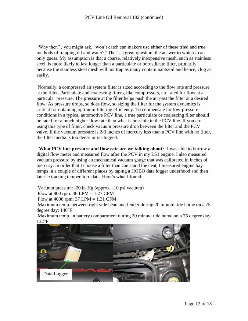
What PCV line pressure and flow rate are we talking about? I was able to borrow a
digital flow meter and measured flow after the PCV in my LS1 engine. I also measured
vacuum pressure by using an mechanical vacuum gauge that was calibrated in inches of
mercury. In order that I choose a filter than can stand the heat, I measured engine bay
temps in a couple of different places by taping a HOBO data logger underhood and then
later extracting temperature data. Here’s what I found:
Vacuum pressure: -20 in-Hg (approx. -10 psi vacuum)
Flow at 800 rpm: 36 LPM = 1.27 CFM
Flow at 4000 rpm: 37 LPM = 1.31 CFM
Maximum temp. between right side head and fender during 20 minute ride home on a 75
degree day: 140°F
Maximum temp. in battery compartment during 20 minute ride home on a 75 degree day:
132°F
Data Logger

PCV Line Oil Removal 102 (continued)
Page 13 of 18
While a coalescing filter is excellent way to trap oil, I have come to find that even in an
automotive application that of course, includes an oil filter, a matched-flow coalescing
filter element will need to be changed often if a particulate filter is not installed upstream.
Also, assuming that most people do not have differential pressure measurement
equipment or even a very accurate vacuum gauge, I now recommend that a good, high-
flow particulate filter be installed after the PCV valve and preferably, away from the
main heat source in your engine bay – your engine. The advantages of this type of filter
are as follows:
1. Like Dana Corp’s MultiTwister oil separation design, the particulate filter’s air-
swirling disc throws the air and liquids against the inside wall of the “can”,
allowing airborn oil and water to coalesce and drop down into the reservoir, or
“quiet zone”.
2. Unlike stainless steel wool – like media, a particulate filter traps a majority of
blowby byproducts that can pass through course, steel wool media.
3. And unlike the typical mesh-type filter, the air exiting the filter is not exposed to
the trapped liquids, which can slosh enough to allow retrainment of oil into the
airstream that is heading into the intake manifold.
4. Compact design fits in areas that are too small for larger catch cans.
5. The filter elements are easily replaced, inexpensive, and are readily available
from distributors throughout the US.
6. Available in both aluminum and glass-body designs. Both can withstand up to
200 degrees F. temperatures.
The as-purchased filter assembly. Yes, it is small, but see the following website for
optional extra-capacity glass and aluminum options:
http://www.conceptualpolymer.com
Now there’s one more thing I should mention – hose type. Do NOT use any old type of
hose for extending the PCV line; use fuel line hose only. I found that there are at least
two types available in automotive supply stores. Since pressure in the hose will be low,
the least expensive type will do just fine. Note some newer vehicles have PCV hoses that
are sound/heat insulated with a foam covering. Some owners of Sierra trucks have
reported that using an aftermarket PCV/fuel hose will allow a high-pitched hissing noise
Zinc body with drain valve

PCV Line Oil Removal 102 (continued)
Page 14 of 18
to be heard with hood open. This should not indicate that there is a leak and does not
cause a warning light to illuminate on the instrument panel.
Hey, what about our “fresh air line”; does it need a “catch can” too? The fresh air line
may see reverse flow of dirty air out of the valve cover and to the air filter housing under
Wide Open Throttle (WOT) conditions. The problem with plumbing a catch can in this
line is that many are designed for a single flow direction only. Allowing a reverse flow of
“dirty” air may make matters worse by adding oil aerosols to the air. This extra oil may
then get pulled into the engine’s intake – just what we are trying to avoid.
So what should we do? Well, you could plumb in two fresh air lines from the valve
cover to the air filter housing, one containing a catch can and check valve that would
allow only reverse-flow air to flow through the catch can (under WOT conditions). The
other hose would include a check valve that allowed air to flow from the air filter housing
to the valve cover, but would block any reverse-flowing, dirty air from flowing through
the catch can-free line.
….OR, if you don’t normally drive WOT to work every day, just leave this line alone.
The bulk of your oily air will be flowing through the PCV valve and your cleverly-
mounted catch can/particulate filter.
Here’re a couple of shots showing the front end mounting setup:
Keep all hoses away
from any drive belts! I
used a black tie-wrap to
pull the hoses together.

PCV Line Oil Removal 102 (continued)
Page 15 of 18
Currently, I am further-researching filter media and its effect on oil entrapment and
vacuum pressure drop. Filtering synthetic oil in particular is a not a simple task, as
airborn oil of this type has a very small molecular size, which allows it to bypass
conventional mesh-type filters very easily. In the meantime, I believe the safest media is
a conventional particulate filter. This type is more or less a single piece and will not
allow hard pieces to be pulled downstream. Stay tuned for more info.
7/2012 (Finally, more info): See next page.
This is where I now have my filter
mounted. Yes, there is a longer path
that the blowby gasses must take but
even so, the total pressure drop is
insignificant.
…and here’s my glass
catch can. It sure is nice to
see how much oil is being
trapped!
PCV Line Oil Removal 102 (continued)
Page 16 of 18
Automotive Air/Oil Separator (Catch Can) Efficiency - Beyond the
Basics Overview: While my "PCV Line Oil Removal 102" outlined Positive Crankcase
Ventilation system function, as well as many types of catch cans/filter designs and their
design attributes and flaws, this "white paper" of sorts will delve deeper into engine
dynamics relating to blow-by gasses along with air/oil separation filter specifics,
advantages and disadvantages.
Let's start with a quick recap. Engine piston movement produces high gas velocities
inside the crankcase. This movement not only causes periodic volume changes within the
crankcase, but also "encourages" oil droplets of varying diameter to become airborne and
sail past internal baffles and common catch can filter media. Now, we know that full load
operation (high blow-by quantity) and low pressure drop at the throttle valve often causes
flow reversal back into the air filter box (but not through the air filter); however, normal
throttle actuations still allow those hard-to catch oil droplets to flow through most catch
cans in high enough quantity to be of concern.
What else produces oil consumption? The crankcase ventilation system is actually only
one path through which oil consumption movement occurs. The other two are the
cylinder/piston rings and valve stem seals.
How much oil is consumed through a crankcase ventilation system (CVS)? According to manufacturers' data, a typical 6 liter engine flows .035 gallons per hour of
crankcase blowby-produced oil, constituting 5% of total oil consumption. As you can see,
the CVS represents a rather small percentage of overall oil consumption. However...........
Deposits: Studies have shown that carbon deposits from CVS are often found on inlet
valves (non-direct injection engines) . Of course, deposit buildup over time results in
degradation of volumetric efficiency. Other areas of deposit accumulation include piston
grooves, causing increased blow-by and subsequent oil consumption. Turbo and super-
charged engines' intercoolers may experience impaired heat transfer due to resinous
deposits of high temperature-withstanding polymer constituents (viscosity index
improvers) and inorganic additives (Ca, Zn, P, and Mg).
While not as common in today's oils, phosphorous, in the form of zinc dithiophosphate
(anti- oxidant or anti-abrasive) can cause chemical destruction of a catalytic converter's
surface, reducing its effectiveness.
Oil droplet(particle) size: Oil carried through the CVS can range in droplet size from
sub-micron to well over 20 microns. Each engine type produces its own droplet size
distribution, although most automotive engineers who are knowledgeable about vehicle
emissions would agree that the majority of oil droplets are smaller than 3 microns. In
fact, many droplets are smaller than even 1 micron. Note: 1 micron = .000039 inch
Common catch can filter media: A common approach to trap oil droplets in crankcase
ventilation systems is to pack "course" (grade 4 or higher) steel wool, a plastic-derived
abrasive pad, or air filter media into a fairly large diameter tube or counterbore. Provided
that the air flow is directed through the filter media just before exiting the assembly, the
basic concept is sound. Please note that some catch cans are designed to route blow-by
gasses in the exact opposite direction (not recommended). Assuming the routing of
gasses is correct, however, there are at least three problems with this design (listed by
highest significance, first):
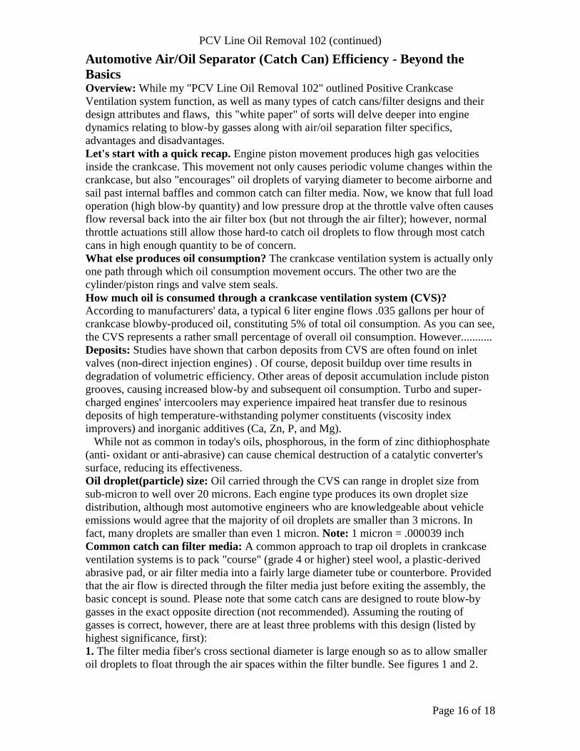
1. The filter media fiber's cross sectional diameter is large enough so as to allow smaller
oil droplets to float through the air spaces within the filter bundle. See figures 1 and 2.
PCV Line Oil Removal 102 (continued)
Page 17 of 18
Figure 1: The effect of media large strand size Figure 2: Filter media strand size comparison
There are generally two reasons for the common selection of .005" - .011" diameter
fibers.
The first is that this grade of media is readily available and the second because finer
media is most often so dense that vacuum pressure drop would be too high.
2. Based upon the cross-sectional area of the filter media (and its enclosure), the velocity
of the blow-by gasses passing through the filter is not high enough to encourage an
optimized rate of "inertial capture", the result of which is shown in blue (figure 1). The
faster a droplet approaches a strand, the greater its momentum and the more likely it is to
collide with the filter media strands. By comparison, smaller, lighter droplets have a
much easier time floating past the large diameter media strands that are very common in
many catch cans. And since gas velocity is simply the flow of gasses divided by the
cross-sectional area of the filter media, larger media enclosures shown in "PCV Line Oil
Removal 102", (pages 5-8) keep gas velocity at a capture efficiency disadvantage. Add to
this design inadequacy the relatively large diameter filter media strands and it's no
wonder plenty of oil works its way into the engine's intake, valves and pistons.
3. Most catch cans' filter media is packed against a much smaller diameter exit or entry
hole. Because of this configuration, gasses are at their highest velocity through a
comparatively small center section of the filter media. The velocity gradient across the
media cross sectional area, then, varies in that it decreases radially toward the outer
circumference of the media. Insufficient "gap space" designed into the internal catch can
geometry is the cause; the result is less than optimum filtration performance.
In addition to what is listed above, many catch can manufacturers recommend and
supply hardware for bolting their products directly to the engine. It is generally well
known among those involved with compressed air systems that when it comes to catching
oil, heat is the enemy. Let's look at the fundamental reason why this is true:
Oil droplets deviate from gas path variations not just because of their momentum but
also because of the difference between the droplet's momentum and that of the gas
surrounding it. When the gas is nearly as dense as the liquid, the gas has a tendency to
"sweep" the oil droplets around the "obstacle" more easily. The more viscous the gas, the
greater the drag it exerts on the airborne oil droplets as they flow around filter media
strands. The viscosity of gas generally increases as temperature increases. Thus,
keeping the filter media and its enclosure in as cool a place as possible is preferable when
trying to maximize oil capture efficiency.

PCV Line Oil Removal 102 (continued)
Page 18 of 18
So, based upon the aforementioned design considerations, the following attributes
contribute to the making of the ideal (highly efficient) catch can. Its design:
1. must route blow-by gasses through the filter media immediately before exiting the
catch can. In other words, the best filter media should be the last thing the gasses
"see" before entering the tubing which carries it to the engine's intake.
2. should contain one or more components that cause blow-by gas to abruptly change
direction when entering the catch can. These design features encourage the largest oil
droplets to drop out of suspension.
3. must contain a primary filter to trap medium-to-large sized oil and water droplets (3-
20 microns). This filter media can be similar to what is now commonly used in
premium catch cans. It can also be what is known as a particulate filter. This filter
media must be free-flowing (low pressure drop) and must have excellent
drainage characteristics. As with all other components of this catch can, the filter
must be capable of withstanding temperatures of 200 degrees F. If stainless steel wire
is used, it must not be a continuously-wound coil, as coalescing oil drops tend to
disengage more easily from the wire if it is formed using non-continuous lengths.
4. should contain a secondary filter that is capable of trapping sub-micron to 3 micron
oil and water droplets. This filter media must not create a large (>3"Hg) vacuum
pressure drop, dry or wet. This filter should last a reasonable length of time before
requiring cleaning or replacement.
5. should feature a sizeable (face) gasket to ensure a leak-proof vacuum and positive
pressure seal. Small cross-section (bore) o-ring seals are not recommended when
sealing vacuum pressure.
6. should be available in multiple sizes and materials (aluminum, zinc, and glass) to
accommodate owners of various types of vehicles and those who wish to see oil/water
accumulation without removing the reservoir or other level detection device.
7. should contain a universal/reversible orientation mounting bracket.
8. should be available at reasonable starting prices, yet be effective at all levels.
Just what would this automotive air/oil separator look like? Perhaps something like this:
Dave