Embed Size (px)
Citation preview
PD Series
Paralleling Switchgear
General Description
Integrating the operation of onsite generators, utility services,
automatic transfer switches, generator controls, and distribution
equipment into a fully functioning system requires the engineering
expertise and dedication to quality that is Kohler paralleling
switchgear.
Kohler’s PD series digital paralleling switchgear provides an
industry-leading platform for command and control of multiple
power sources. Designed to be integrated with Kohler generator
sets or combined with other major brands of generation equipment,
the PD series delivers outstanding reliability along with the most
intuitive user interface in the industry.
The PD series is extremely flexible. Incorporating Kohler’s
patented mode configuration technology, the owner may select from
a variety of operational parameters and sequences without any
additional cost. In addition to the digital control interface, the PD
series may be constructed with any of the more traditional metering,
control, and other component requirements based on an engineer’s
or owner’s preferences (see ED options).
The PD Series paralleling controls are available in:
� PD-200: UL 891 listed and labeled switchboard
� PD-300: UL 1558 listed and labeled switchgear
� PD-400: UL listed and labeled medium voltage switchgear
Standard Features
� 15 in. color graphical user interface (touch screen),
Windows� CE-based
� Digital real (kW) and reactive (kVAR) load sharing
� Digital synchronizer
� User-definable generator management
� User-definable load add/shed control
� Modbus RS485 and TCP/IP communications connections
� Internal web server
� Complete system metering, annunciation, settings, and control
functions through touch screen
� Event monitoring and logging
� Power trend measurements
Available Applications
� Emergency standby
� Prime power
� Base load (peak shave)
� Import/export mode (peak shave)
� Isolate (interruptible rate)
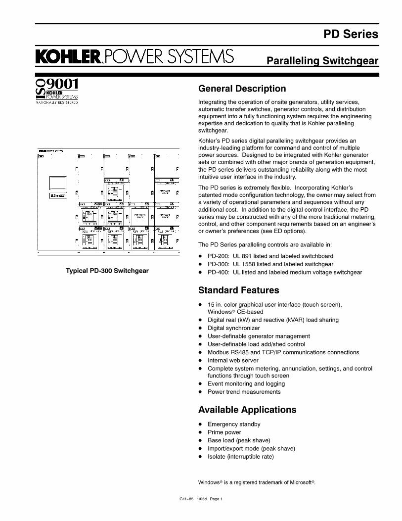
Typical PD-300 Switchgear
Windows� is a registered trademark of Microsoft�.
G11--85 1/05d Page 1
G11--85 1/05d Page 2
System Configurations
PD-200 Series
The PD-200 series product offering is UL 891 listed and allows
for extreme flexibility in design while providing a strong
standard for safety and performance. Features include:
� PD series digital system control standard
� Rear access standard, front access available
� Shallow depth (36--42 in. available)
� UL 489 fixed or drawout breakers for generator sets, utility,
and distribution
� Molded-case breakers available for distribution
� Transfer switches can be mounted in switchgear lineup
� Bus ratings through 10,000 amps/200 kA withstand
� Complete selection of breaker manufacturers, trip options,
and power monitoring
� NEMA 1, NEMA 3R walk-up and walk-in available
PD-300 Series
Offering the highest standard in bus withstand and breaker
ratings, the PD-300 series is listed under UL 1558. Featuring
drawout breakers as standard, the PD-300 series is designed
with reliability and serviceability in mind. Features include:
� PD series digital system control standard
� UL 1066 drawout breakers for generator sets, utility, and
distribution
� Complies with ANSI C37.20.1
� Bus ratings through 6,000 amps/200 kA withstand
� Complete selection of breaker manufacturers, trip options,
and power monitoring
� NEMA 1, NEMA 3R walk-up and walk-in available
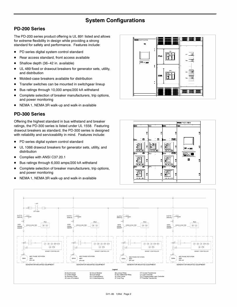
Legend
25 Synchronizer27 Undervoltage32 Reverse Power40 Loss of Excitation
52 Circuit Breaker59 Overvoltage81O Overfrequency81U Underfrequency
86 Lockout Relay87 Bus Differential RelayAF Amp FrameAT Amp Plug
CT Current TransformerLC Load ControllerPLC Programmable Logic ControllerPT Potential Transformer
G11--85 1/05d Page 3
System Configurations, continued
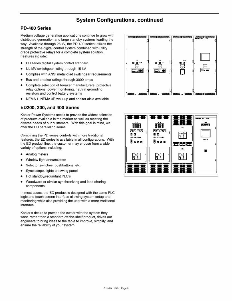
PD-400 Series
Medium voltage generation applications continue to grow with
distributed generation and large standby systems leading the
way. Available through 26 kV, the PD-400 series utilizes the
strength of the digital control system combined with utility
grade protective relays for a complete system solution.
Features include:
� PD series digital system control standard
� UL MV switchgear listing through 15 kV
� Complies with ANSI metal-clad switchgear requirements
� Bus and breaker ratings through 3000 amps
� Complete selection of breaker manufacturers, protective
relay options, power monitoring, neutral grounding
resistors and control battery systems
� NEMA 1, NEMA 3R walk-up and shelter aisle available
ED200, 300, and 400 Series
Kohler Power Systems seeks to provide the widest selection
of products available in the market as well as meeting the
diverse needs of our customers. With this goal in mind, we
offer the ED paralleling series.
Combining the PD series controls with more traditional
features, the ED series is available in all configurations. With
the ED product line, the customer may choose from a wide
variety of options including:
� Analog meters
� Window light annunciators
� Selector switches, pushbuttons, etc.
� Sync scope, lights on swing panel
� Hot standby/redundant PLC’s
� Woodward or similar synchronizing and load sharing
components
In most cases, the ED product is designed with the same PLC
logic and touch screen interface allowing system setup and
monitoring while also providing the user with a more traditional
interface.
Kohler’s desire to provide the owner with the system they
want, rather than a standard off-the-shelf product, drives our
engineers to bring ideas to the table to improve, simplify, and
ensure the reliability of your system.
G11--85 1/05d Page 4
Applications
PD series paralleling switchgear is extremely versatile and
can be configured for on the fly operational mode change.
Kohler’s patented field configurable operation modes can
allow the owner to select a system that will provide soft-load
closed transition emergency operation today and extended
parallel/peak shave in the future without significant
modifications.
Typical applications for the PD series include:
Standby
ATS Start
A start signal from an automatic transfer switch or other
control device starts all generator sets. The generators
synchronize and connect to the paralleling bus.
Utility Breaker Sensing
In many systems, transfer switches are not present. When
the utility fails, the utility breaker opens. The PLC logic starts
the generator sets and connects them to the generator set
paralleling bus. When the required number of generator sets
are online, the tie breaker closes.
Return of Utility
After utility power is restored, the return-to-utility sequence
starts. Several options are available for return of utility power.
ATS Transfer: Standard, delayed transition or closed
transition switches can restore the load to the utility source.
Circuit Breaker Transfer: Where a system does not employ
automatic transfer switches, the system breakers can effect
transfer in multiple modes:
Open Transfer: The tie breaker opens and, after a time
delay, the utility breaker closes.
Soft Transfer: The generator bus synchronizes to the
utility. When synchronized, the utility breaker closes. The
switchgear soft-unloads the generator sets and then opens
the generator bus tie breaker.
Prime Power
A system-start signal starts all generator sets. The generator
sets synchronize and connect to the generator set paralleling
bus.
Isolate (Interruptible Rate)
A system-start signal starts all generator sets. The generator
sets synchronize and connect to the generator set paralleling
bus. With all generator sets online, the generator bus
synchronizes to the utility and the generator bus tie breaker
closes. The generator sets ramp up to assume system load.
When the power flow across the utility breaker reaches a
preset level, the utility breaker opens.
Base Load Generators (Peak Shave)
A system-start signal starts the generator sets. The generator
sets synchronize and connect to the generator set paralleling
bus. With all generator sets connected, the generator bus
parallels to the utility and the generator bus tie breaker closes.
The generator sets soft-load to a preset, user-adjustable kW
level.
Generator set output remains constant and utility power
fluctuates to supply the difference between the generator set
output and the load requirement. When the generator set
output exceeds the system load requirements, the excess
power is exported to the utility.
Import/Export (Peak Shave)
A system-start signal starts the generator sets. The generator
sets synchronize and connect to the generator paralleling bus.
With all generator sets connected, the generator bus parallels
to the utility and the generator bus tie breaker closes. The
generator sets soft-load to a preset, user-adjustable kW power
flow across the utility breaker. The power flow to the utility
remains constant and the generator set power output
fluctuates to meet the requirements of the load.
If the import/export level is positive, the system imports a set
power level from the utility; if the import/export level is
negative, the system exports a set power level to the utility.
If the load requirement exceeds the generator set rating, the
generator set produces its rated power and the utility supplies
the difference.
G11--85 1/05d Page 5
Touch Screen Interface
The PD series of digital switchgear incorporates a high
resolution touch screen interface (HMI) to provide control and
monitoring of all system parameters in one strategic location.
Unlike older style switchgear that requires significant panel
space for each generator set’s analog metering, annunciation,
and control switches, the PD series locates components in
less than one third the traditional space. This approach leads
to a more reliable system through wiring and component
reduction as well as a more user-friendly interface. Rather
than setting system parameters through special programmers,
small input screens and multiple analog devices scattered
throughout the lineup, the user works from a single location for
all operations.
The operator interface is configured in a user-friendly tab
format with direct access to multiple levels of control and
monitoring and runs in Windows� CE environment. Screen
programs are held on a standard PC card that is simple to
upgrade as future customer requirements develop. User
programming is performed through a password-protected
pop-up keypad available on all screens. Each system
includes:
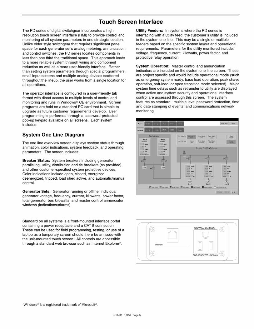
System One Line Diagram
The one line overview screen displays system status through
animation, color indications, system feedback, and operating
parameters. The screen includes:
Breaker Status: System breakers including generator
paralleling, utility, distribution and tie breakers (as provided),
and other customer-specified system protective devices.
Color indications include open, closed, energized,
deenergized, tripped, load shed active, and automatic/manual
control.
Generator Sets: Generator running or offline, individual
generator voltage, frequency, current, kilowatts, power factor,
total generator bus kilowatts, and master control annunciator
windows (indications/alarms).
Utility Feeders: In systems where the PD series is
interfacing with a utility feed, the customer’s utility is included
in the system one line. This may be a single or multiple
feeders based on the specific system layout and operational
requirements. Parameters for the utility monitored include:
voltage, frequency, current, kilowatts, power factor, and
protective relay operation.
System Operation: Master control and annunciation
indicators are included on the system one line screen. These
are project specific and would include operational mode (such
as emergency system ready, base load operation, peak shave
operation, soft-load, or open transition mode selected). Major
system time delays such as retransfer to utility are displayed
when active and system security and operational interface
control are accessed through this screen. The system
features as standard: multiple level password protection, time
and date stamping of events, and communications network
monitoring.
Standard on all systems is a front-mounted interface portal
containing a power receptacle and a CAT 5 connection.
These can be used for field programming, testing, or use of a
laptop as a temporary screen should there be an issue with
the unit-mounted touch screen. All controls are accessible
through a standard web browser such as Internet Explorer�.
Windows� is a registered trademark of Microsoft�.
G11--85 1/05d Page 6
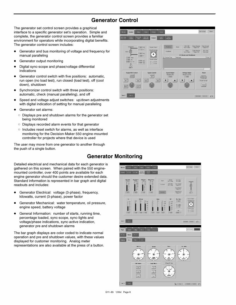
Generator Control
The generator set control screen provides a graphical
interface to a specific generator set’s operation. Simple and
complete, the generator control screen provides a familiar
environment for operators while incorporating digital benefits.
The generator control screen includes:
� Generator and bus monitoring of voltage and frequency for
manual paralleling
� Generator output monitoring
� Digital sync-scope and phase/voltage differential
indications
� Generator control switch with five positions: automatic,
run open (no load test), run closed (load test), off (cool
down), shutdown
� Synchronizer control switch with three positions:
automatic, check (manual paralleling), and off
� Speed and voltage adjust switches: up/down adjustments
with digital indication of setting for manual paralleling
� Generator set alarms:
� Displays pre and shutdown alarms for the generator setbeing monitored
� Displays recorded alarm events for that generator
� Includes reset switch for alarms, as well as interface
monitoring for the Decision-Maker 550 engine-mounted
controller for projects where that device is used
The user may move from one generator to another through
the push of a single button.
Generator Monitoring
Detailed electrical and mechanical data for each generator is
gathered on this screen. When paired with the 550 engine-
mounted controller, over 400 points are available for each
engine generator should the customer desire extended data.
Standard information is represented in bar graph and digital
readouts and includes:
� Generator Electrical: voltage (3-phase), frequency,
kilowatts, current (3-phase), power factor
� Generator Mechanical: water temperature, oil pressure,
engine speed, battery voltage
� General Information: number of starts, running time,
percentage loaded, sync-scope, sync-lights and
voltage/phase indications, sync-active indication,
generator pre and shutdown alarms
The bar graph displays are color coded to indicate normal
operation and pre and shutdown values, with these values
displayed for customer monitoring. Analog meter
representations are also available at the press of a button.
G11--85 1/05d Page 7
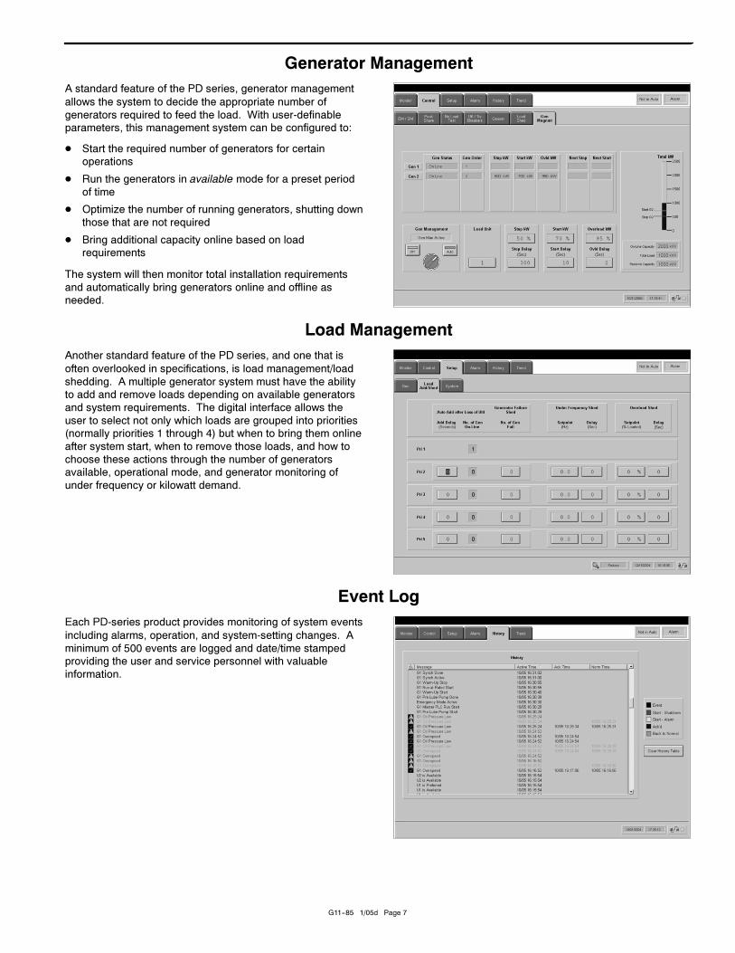
Generator Management
A standard feature of the PD series, generator management
allows the system to decide the appropriate number of
generators required to feed the load. With user-definable
parameters, this management system can be configured to:
� Start the required number of generators for certain
operations
� Run the generators in available mode for a preset period
of time
� Optimize the number of running generators, shutting down
those that are not required
� Bring additional capacity online based on load
requirements
The system will then monitor total installation requirements
and automatically bring generators online and offline as
needed.
Load Management
Another standard feature of the PD series, and one that is
often overlooked in specifications, is load management/load
shedding. A multiple generator system must have the ability
to add and remove loads depending on available generators
and system requirements. The digital interface allows the
user to select not only which loads are grouped into priorities
(normally priorities 1 through 4) but when to bring them online
after system start, when to remove those loads, and how to
choose these actions through the number of generators
available, operational mode, and generator monitoring of
under frequency or kilowatt demand.
Event Log
Each PD-series product provides monitoring of system events
including alarms, operation, and system-setting changes. A
minimum of 500 events are logged and date/time stamped
providing the user and service personnel with valuable
information.
© 2002, 2003, 2005 by Kohler Co. All rights reserved.
DISTRIBUTED BY:
G11--85 1/05d Page 8
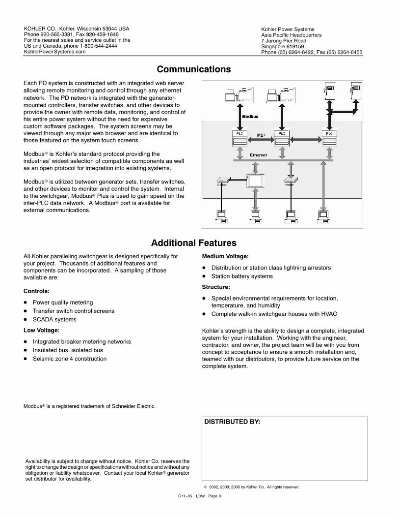
Communications
Each PD system is constructed with an integrated web server
allowing remote monitoring and control through any ethernet
network. The PD network is integrated with the generator-
mounted controllers, transfer switches, and other devices to
provide the owner with remote data, monitoring, and control of
his entire power system without the need for expensive
custom software packages. The system screens may be
viewed through any major web browser and are identical to
those featured on the system touch screens.
Modbus� is Kohler’s standard protocol providing the
industries’ widest selection of compatible components as well
as an open protocol for integration into existing systems.
Modbus� is utilized between generator sets, transfer switches,
and other devices to monitor and control the system. Internal
to the switchgear, Modbus� Plus is used to gain speed on the
inter-PLC data network. A Modbus� port is available for
external communications.
Additional Features
All Kohler paralleling switchgear is designed specifically for
your project. Thousands of additional features and
components can be incorporated. A sampling of those
available are:
Controls:
� Power quality metering
� Transfer switch control screens
� SCADA systems
Low Voltage:
� Integrated breaker metering networks
� Insulated bus, isolated bus
� Seismic zone 4 construction
Medium Voltage:
� Distribution or station class lightning arrestors
� Station battery systems
Structure:
� Special environmental requirements for location,
temperature, and humidity
� Complete walk-in switchgear houses with HVAC
Kohler’s strength is the ability to design a complete, integrated
system for your installation. Working with the engineer,
contractor, and owner, the project team will be with you from
concept to acceptance to ensure a smooth installation and,
teamed with our distributors, to provide future service on the
complete system.
Modbus� is a registered trademark of Schneider Electric.
Kohler Power SystemsAsia Pacific Headquarters7 Jurong Pier RoadSingapore 619159Phone (65) 6264-6422, Fax (65) 6264-6455
Availability is subject to change without notice. Kohler Co. reserves theright to change the designor specificationswithout noticeandwithout anyobligation or liability whatsoever. Contact your local Kohler� generatorset distributor for availability.
KOHLER CO., Kohler, Wisconsin 53044 USAPhone 920-565-3381, Fax 920-459-1646For the nearest sales and service outlet in theUS and Canada, phone 1-800-544-2444KohlerPowerSystems.com