Embed Size (px)
Citation preview
ROBINSON INSTRUMENTS
Page : 1
January 2001
Partial Discharge
Training Course
HIPOTRONICSTHE MEASURE OF A LEADER
ROBINSON INSTRUMENTS
Runcorn
England

ROBINSON INSTRUMENTS
Page : 2
1 SAFETY IN HV TESTING .................................................................................................................. 4
1.1 INTRODUCTION ............................................................................................................................... 4 1.2 BASIC PREMISE ............................................................................................................................... 4 1.3 PERMANENT TEST LOCATIONS (E.G. FACTORY, TEST DEPT. ETC.) ................................................. 4 1.4 TEMPORARY LOCATIONS, ON-SITE TESTING ................................................................................... 6 1.5 FINAL COMMENT. ........................................................................................................................... 7
2 MECHANISM AND MEASUREMENT ............................................................................................ 8
2.1 WHAT IS A PARTIAL DISCHARGE? ................................................................................................... 8 2.1.1 Physical Process of a Partial Discharge ................................................................................... 8
2.2 WHY DETECT AND MEASURE PARTIAL DISCHARGES? .................................................................... 10 2.3 HOW TO MEASURE PARTIAL DISCHARGES? ................................................................................... 11 2.4 CALIBRATION OF MEASUREMENTS. ............................................................................................... 12 2.5 OTHER METHODS OF DETECTION. ................................................................................................. 12 2.6 AC OR DC MEASUREMENT. .......................................................................................................... 13
3 DISCHARGE DETECTION INSTRUMENTS ................................................................................ 14
3.1 PRACTICAL DISCHARGE DETECTORS............................................................................................. 14 3.2 STRAIGHT DISCHARGE DETECTION. .............................................................................................. 14
3.2.1 Discharge Detector Model 5, Type 700 ................................................................................... 14 3.2.2 Calibration with DD5 .............................................................................................................. 14 3.2.3 High Voltage Injection - 700CRH ........................................................................................... 15 3.2.4 Low Voltage Injection - 700CRL ............................................................................................. 15 3.2.5 DD5 Facilities ......................................................................................................................... 17
3.3 MEASUREMENT SENSITIVITY ........................................................................................................ 18 3.4 BRIDGE TYPE DISCHARGE DETECTORS. ........................................................................................ 18
3.4.1 The Balanced Circuit and Bridge Techniques. ........................................................................ 18 3.5 NOISE REJECTING DETECTORS. ..................................................................................................... 19
4 INTERFERENCE NOISE COUPLING ........................................................................................... 20
4.1 INTRODUCTION. ............................................................................................................................ 20 4.2 COMMON MODE NOISE. ................................................................................................................ 20 4.3 INDUCED INTERFERENCE NOISE .................................................................................................... 20 4.4 EARTH INDUCED NOISE. ............................................................................................................... 20 4.5 NOISE COUPLED FROM THE SUPPLY LINE ...................................................................................... 21 4.6 NOISE MINIMISATION AND TEST CIRCUIT ARRANGEMENT ............................................................ 21
5 NOISE REJECTION PRINCIPLES ................................................................................................. 22
5.1 INTRODUCTION. ............................................................................................................................ 22 5.2 PULSE DISCRIMINATION SYSTEM. ................................................................................................. 22
5.2.1 External pulse rejection. .......................................................................................................... 22 5.2.2 Calibration ............................................................................................................................... 23 5.2.3 Inductively Coupled Pulse Rejection. ...................................................................................... 23 5.2.4 Radio Frequency Interference. ................................................................................................ 23
5.3 NATURALLY SCREENED COMPONENTS. ......................................................................................... 24 5.3.1 Calibration with HV Input Unit ............................................................................................... 24
5.4 TWO COMPONENT TESTING. ......................................................................................................... 25
6 GENERAL TESTING APPLICATIONS ......................................................................................... 26
6.1 INTRODUCTION. ............................................................................................................................ 26 6.2 TRANSFORMER TESTING ............................................................................................................... 26
6.2.1 Tests without Bushing Taps. .................................................................................................... 26 6.2.2 Tests with Bushing Taps. ......................................................................................................... 26 6.2.3 Voltage Measurement. ............................................................................................................. 26 6.2.4 Three Phase Measurements. .................................................................................................... 27

ROBINSON INSTRUMENTS
Page : 3
6.2.5 Variable Supply Frequency Testing. ........................................................................................ 27 6.2.6 Bushing Testing. ...................................................................................................................... 27
6.3 ROTATING MACHINES ................................................................................................................... 28 6.3.1 Discharge Pulse Superposition ................................................................................................ 28
6.4 GENERAL COMPONENTS ................................................................................................................ 29
7 INTERPRETATION OF DISCHARGES ......................................................................................... 30
7.1 GENERAL. ..................................................................................................................................... 30 7.2 NOISE AND DISTURBANCES. .......................................................................................................... 30 7.3 PARTIAL DISCHARGES. .................................................................................................................. 30 7.4 IDENTIFICATION OF TYPE OF DISCHARGE. ...................................................................................... 31
8 DIGITAL PARTIAL DISCHARGE DETECTION ......................................................................... 32
8.1 GENERAL ...................................................................................................................................... 32 8.2 DDX7000 ..................................................................................................................................... 32
8.2.1 DDX Features .......................................................................................................................... 32 8.3 DDX8003 ..................................................................................................................................... 33
9 NOISE SUPPRESSION TECHNIQUES .......................................................................................... 34
9.1 INTRODUCTION: ............................................................................................................................ 34 9.2 INTERFERENCE NOISE TYPES: ....................................................................................................... 34 9.3 TEST APPLICATIONS: ..................................................................................................................... 34 9.4 CLASSES OF TECHNIQUE APPLIED: ................................................................................................ 35
9.4.1 Noise Avoidance ...................................................................................................................... 35 9.4.2 NOISE ELIMINATION ............................................................................................................ 38

ROBINSON INSTRUMENTS
Page : 4
P A R T I A L D I S C H A R G E S
1 SAFETY IN HV TESTING
1.1 Introduction
The following recommendations are being presented to users of the Robinson Instruments HV Test Equipment.
These recommendations are to encourage a high standard of safety in the establishment and use of such equipment and to reduce the possibility of injury to personnel.
The information given below has been prepared in co-operation with the Health and
Safety Executive.
To minimise the possibility of dangerous accidents, we request all users of HV equipment to implement the safety measures given below and thus establish safe working conditions for all such high voltage tests.
A careful study of the book "Safety in Electrical Testing - a Code of Good Practice" published by the Association of Electrical Machining Trades, would be of great benefit.
1.2 Basic Premise
High voltage is dangerous.
Great care must be taken when setting up and using equipment that involves high voltage. All test engineers and operators of such equipment are subject to human failings. It must not be assumed that the experience and expertise of a test engineer can replace correct safety procedures.
Employers of test engineers cannot avoid their responsibility by leaving such tests "in the hands of their expert".
The employer must provide adequate support, backup, instruction and equipment so that every test carried out is safe in every aspect.
An employer must insist that safety measures are implemented and they must issue clear written instructions in these matters and monitor that these are complied with on a regular basis.
A test engineer must be provided with such instructions and carry them out.
The cost and time involved in setting up safe testing conditions is small in comparison with the value of human life.
1.3 Permanent Test Locations (e.g. Factory, Test Dept. etc.)
a) A permanent HV Test area should be allocated and provided with a good, low resistance earth system with heavy-duty connectors easily available and clearly marked.
ROBINSON INSTRUMENTS
Page : 5
b) A substantial earthing stick, efficiently connected to earth, must be provided in the test area and this must be used to earth the HV supply point and test sample before personnel make contact with these items. All un-used capacitors in the area must be shorted out and connected to ground at all times. The sample, HV Transformer and measurement circuit must be efficiently earthed.
c) A system of red/green warning lamps, notices and audible warning horn/tone must be set up around the area. Bright flashing lamps are recommended. These red and green lamps must be so connected that a failure of a red lamp will not indicate that the area is safe to enter. The red lamp will be ON when the high voltage supply is ON. The green lamps will be ON only when the high voltage supply is OFF. Personnel must NOT enter the test area when the red lamps are on or when no lamps are illuminated (indicating a failure of this warning system). This warning system must be regularly checked and tested for correct operation.
d) No test engineer will be allowed to work alone. A second person must be present who has been trained to observe that the system is being safely operated. Both persons must know the location of the system supply isolator switch, the emergency "OFF" switch or button and safety/emergency procedures.
e) A permanent partition or fence must be erected around this area. This construction must be connected to earth and bonded together. It must give good mechanical protection and prevent personnel or other objects from coming near the HV circuits. It must surround on all sides the HV supply and test sample with adequate clearance.
f) Entrances to this area must be mechanically key interlocked with the main power supply isolator so that should any one of these entrances be opened during a high voltage test, then the voltage is automatically switched off. An earthing switch should be provided and incorporated in the interlocking scheme such that access to the enclosure is only possible with the HV Test Supply terminals earthed.
g) The high voltage transformer will be located inside the enclosure. All control panels, measurement instruments and isolator switches must be located outside this fenced area.
No direct connection to the high voltage must be brought out from inside the enclosure.
h) No person shall remain in the HV test area for any reason whilst HV tests are in progress.
i) The Discharge Detector (Test equipment), control unit, regulator, measurement equipment and all other similar items outside the test area must be connected to earth. Substantial sleeved earth braid fitted with lugs should be used.
j) All power leads and signal cables must be insulated and sheathed and maintained in a good condition and protected from damage. Plugs, sockets and connectors should likewise be maintained in a good condition.
k) HV connections in the test area should be well made (crocodile clips must not be used). HV leads should be kept clear of any earthed objects. Should a connection fail during an HV test the engineer must be particularly careful to use the earthing stick to discharge any item that may retain a charge and to ground the HV supply point.
l) The control unit must be fitted with a lockable isolator.
ROBINSON INSTRUMENTS
Page : 6
1.4 Temporary Locations, on-Site Testing
Safety "on site" is just as important as at a fixed location. Nearly all the recommendations for Permanent Test Locations also apply to on site testing.
The necessary safety equipment will have to be provided and transported to the site by the engineers.
It cannot be assumed that such equipment is available "on site".
The following points should be noted: -
a) Prior to setting up a test, on site, a discussion should be held with the occupier on safety procedures to be followed and any necessary documentation obtained before testing starts.
b) Investigation of the existing site earth system and its quality must be made and improvements carried out to this earth prior to any HV tests if required.
c) Connections to the site earth form part of the HV measurement circuit and are the responsibility of the test engineer. He should bring to the site suitable earth leads, fitted with lugs and connect them in a safe manner. All items must be correctly earthed.
d) The engineer must also bring, connect up and use an earthing stick.
e) A "test area" surrounding, on all sides, the sample to be tested and enclosing the HV supply and measurement circuit must be defined.
f) Safety barriers, portable fences or tapes are to be set up surrounding the test area.
There must be a clear space between any part of the barrier and the nearest exposed HV connection of at least 3 metres (10 feet).
This spacing allows clearance should any person "fall" into the area across a barrier. These barriers should have an interlock circuit if possible.
g) Portable flashing red/green warning lamps and warning notices must be positioned on or next to the barrier, on ALL sides. An audible warning can also be used in addition to these lamps. The red and green warning lamps must be connected and maintained as previously described in section 3(c) above.
h) The COMPLETE HV test area must be under observation by competent personnel during HV tests to ensure that no person "strays" into the test area.
i) The test engineer must not work alone and all concerned must know where the supply isolation switch is located and where the emergency "OFF" button or switch is. Such assistants must be trained in safety/emergency procedures.
j) The control unit must have a lockable isolator in the main test power supply and this must be used to remove the power, before entering the test area. This isolator must be OUTSIDE the HV test area.
k) The Discharge Detector (Test Equipment), regulator and control unit must be located outside the HV test area. The power supply lead between the HV transformer and regulator must be of sufficient length so that the regulator is outside the test area and the HV transformer is centrally located inside the test area adjacent to the sample and measurement circuit.
l) Because "temporary" barriers may not have interlock wiring or can be by-passed by personnel (e.g. "ducking under") a close watch must be kept. Nobody, not even the test engineer, must enter the area unless the supply is switched off and

ROBINSON INSTRUMENTS
Page : 7
the isolator locked.
THEN the earthing stick MUST be used to ground the HV supply and sample.
m) Particular care must be taken with supply and signal leads on site to avoid wear or damage.
n) The movement of other personnel, forklift trucks, cranes etc. on site must be noted and warnings issued to the site staff as to the dangers in approaching the HV test area.
1.5 Final Comment.
We recommend that all users of HV test equipment be issued with clear written instructions that emphasize simply the above-mentioned matters.
These instructions should have simple diagrams that not only show the equipment connection BUT ALSO the necessary safe position of the equipment and safety barriers, lights etc.
The necessary safety equipment must be provided and used correctly at every location.
High Voltage and Discharge detection testing can be safe - make sure, take steps now to make it safe.
ROBINSON INSTRUMENTS
Page : 8
P A R T I A L D I S C H A R G E S
2 MECHANISM AND MEASUREMENT
2.1 What is a Partial Discharge?
Definition:
In electrical power components, such as cables, transformers switchgear etc., partial discharges may occur during the working life of the equipment and their presence can erode the insulation of the equipment and so reduce its useful life. Partial discharge testing has been widely used to detect these defects before equipment is installed on the power system, so as to improve the reliability and to minimise failure costs of important capital plant.
This section describes the basic physical processes involved in a partial discharge and also the techniques that can be used for their detection and measurement.
2.1.1 Physical Process of a Partial Discharge
The breakdown that forms the partial discharge normally occurs in air (or another gas) and is limited by the presence of some solid insulation material that is in series with the breakdown path. The presence of this insulating material greatly limits the actual current that will flow as a result of the partial breakdown.
As an example, a simplified insulation system is shown in Fig. 1.
This simple system is made up from two equal thicknesses of insulation, (about .6 mm) PVC enclosing a third thickness of air. Because the PVC has a higher dielectric constant than air, the electric stress will be concentrated in the air gap. As air has a breakdown voltage of about 25kV/cm, the gap shown will withstand a stress of 1.5 kV. With the system shown, this stress will exist when a voltage of 2.5 kV is applied across the electrodes, X1 and X2. When the air actually breaks down under the influence of the electric field across the gap, gas molecules in the air become ionised into positively charged ions and free negative electrons. (Fig.2) The positively charged ions will be attracted to the insulating surface that is nearer to the electrode that is negative and the electrons will be attracted to the opposite, positive face. When these charges arrive on the insulating surface, they are
A PARTIAL DISCHARGE IS A VOLTAGE BREAKDOWN THAT OCCURS BETWEEN TWO ELECTRODES BUT
DOES NOT COMPLETELY BRIDGE THOSE TWO ELECTRODES.
ROBINSON INSTRUMENTS
Page : 9
unable to flow any further towards the electrodes because of the presence of the insulation. So these ionic charges will accumulate on the surfaces.
Now, as the discharge continues, there will exist two components of electric field across the air gap; the first due to the applied voltage operating from X1 to X2, and the second due to the accumulating deposited charges on the insulating surfaces acting in the opposite direction, from X2 to X1. These two opposite fields will tend to counteract each other, and the longer the discharge continues the more charge will be deposited. This will continue until the resultant field in the air gap is reduced so that the conducting path through the air cannot be maintained, and the discharge extinguishes. (Fig.3) This discharge action is very fast acting and this single process is likely to be complete within 10-100 n sec. While a high electric field is required to start the process, once a discharge channel is formed this will persist until the field is reduced to about 1/10 of the initial level.
{If the applied voltage were D.C. then the deposited charges would prohibit any further discharges until the charges can leak away and the opposing electric field reduces, which may take many seconds. The resultant electric field will correspondingly increase until another discharge occurs.
Much more interest exists when considering discharges under AC stresses.}
After the discharge has taken place while the applied voltage is positive, charge will be deposited as described above. Then, the applied voltage will continue through the alternating cycle, will reduce through zero and reverse its polarity. (Fig. 4) This change in supply voltage will not affect the deposited charges that exist on the faces of the insulation that, during these few milliseconds, will remain fixed. However, when the applied voltage has reduced to zero, the electric field remaining in the gap will be entirely due to the presence of the deposited charges. As the applied voltage now reverses, the electric field due to the deposited charges will now be adding to the field due to the applied voltage. The resultant electric stress across the gap can now be enough to break down the air and cause another discharge, in the reverse direction, even while the applied voltage within the alternating cycle is very low. (Fig. 4) This reverse discharge will tend to cancel the existing deposited charge. (Fig. 5) As the voltage across the gap continues to increase toward the negative peak, a further discharge can occur, Figs. 6&7. This process will continue through successive cycles (Figs 8 - 16)
Thus, with a supply of alternating voltage, discharges will occur on every half cycle of the supply. Fig. 17 shows how the voltage across the gap will rise and fall throughout a cycle, and that discharges will normally occur while the applied voltage is increasing from zero toward its' voltage peak, positive or negative.
In practice, this idealised discharge sequence will be made more complicated by the existence of transverse electric fields across the surface of the cavity and other conduction effects. However, the basic mechanism will remain as described. These discharges would be seen on a discharge detector display as shown in either Fig 18 or 19.
Fig. 20 shows a rather idealised model of a simple capacitor that has a void within the insulation. If this capacitor has an electrode area 200mm x 200mm and the polythene insulation is 5mm thick, and if the void has a radius of 1mm and is 0.5mm across, then the void will discharge when the applied voltage reaches 2.5kV and the discharge magnitude should be measured as about 7pC.
ROBINSON INSTRUMENTS
Page : 10
This calculation does make a number of assumptions but does give some idea of the physical scale that is concerned with partial discharge detection.
Such discharge sites may occur within the insulation of any H.V. equipment; cables; switchgear; bushings; CTs; VTs; power transformers etc.
The instance discussed, of an enclosed air gap, is one physical example of a discharge site. Many other possible situations do exist; discharges across a surface, discharges into air (known in the U.K. as Corona), discharges under oil, or any other instance where the breakdown path only partially bridges the electrodes.
2.2 Why detect and measure partial discharges?
When an insulation engineer is designing some high voltage equipment, he will try to ensure that the complete item can be produced at a low cost and in the smallest physical size. Thus he will wish to minimise the thickness of insulation used and hence work at high electrical stress. If, through some design weakness or manufacturing fault, partial discharges occur on the equipment, then during every cycle of the mains frequency supply, the discharge action will continue.
Each discharge pulse contains certain energy and this is dissipated on the insulation surface by ionic bombardment that can cause local heating and lead to production of chemical by-products. This action can then locally degrade the insulation and enlarge the fault. This degradation will take place over a number of years, and the normal service life, which could be 20 - 40 years, may be greatly reduced. This process may continue until the insulation fails completely which may be dangerous, expensive to repair and inconvenient to the user.
The partial discharge is an indication of a physical defect. The defect may possibly have been present since the equipment was first installed, and thus the discharge itself can be considered as the cause of the degradation problem; it is also quite possible that the discharge is a symptom of some mechanical problem in the equipment that has developed through use or abuse: e.g. de-lamination in a bushing; stresses caused by overheating in a transformer; separation of insulation from a conductor caused by heat cycling in a cable; damage to stress control in a stator bar winding caused by vibration or corrosion. The existence of the partial discharge can therefore be considered as either the cause of damage, or the effect of damage; in either case they indicate some potential defect in the insulation system.
So, the purchasers of equipment such as the generators and distributors of electric power, specify to their equipment supplier, that the cables, switchgear etc. must be tested and shown not to contain any faults generating partial discharges. This test then provides a good non-destructive means of assessing the quality of a finished item in measurable terms. For example, different manufacturers would all have to satisfy this test requirement and so, in this respect, the quality of their product can be proved to be comparable.
A number of standard specifications exist that relate to different H.V. equipment. These specifications will normally define minimum requirements for the discharge measuring equipment being used. The test voltages to be applied are defined, usually as a percentage above normal working voltage, and the maximum permitted level of partial discharge will be stated.
ROBINSON INSTRUMENTS
Page : 11
Although the specifications do define a precise level of discharge to be used as an acceptance level, it is not possible to state that all discharges greater than this level are definitely harmful and that any below it are harmless. However, it is accepted that an item with no partial discharges is better than one with discharges, and that an item with small discharges is better than one with large discharges. The values defined in specifications tend to be established in relation to what it is possible to measure, rather than the precise meaning of that value.
Although meeting specifications is an overriding motivation to make discharge measurements, they are also used as a quality control test by some component manufacturers to meet purely internal standards.
2.3 How to measure Partial Discharges?
When a Partial Discharge occurs, very small amounts of energy are released in a number of forms: heat, sound, light and electrical. By far the most common means of detecting partial discharges in practice is electrical and the basic electrical principle is described below with reference to Fig. 20.
This figure shows a sample of insulation containing a single air filled cavity and the equivalent electrical circuit diagram. Of these three capacitive elements, Cx represents the capacitance of the sound body of the insulation and is effectively equal to the total capacitance of the test item. Cz represents the small cavity and Cy the insulation physically in series with the cavity. As the voltage across the item increases, voltages across these three elements will increase so that:
Vx = Vy + Vz
When the voltage Vz is sufficient to breakdown the air inside the cavity, Vz will be short circuited by the discharge and will become very nearly zero. Now the equivalent circuit will become as shown in Fig. 21. However, this assumes that Vx and Vy have remained unchanged and that these two different voltages are now connected in parallel! This impossible situation is corrected by a small flow of charge from Cx into Cy to equalize the voltages, as in Fig. 22. So a very small voltage dip is caused across the terminals of the test object.
It is not practical to detect this voltage dip directly, so an external coupling capacitor, Cb, is connected in the circuit, as in Fig. 23. Now Cb and the small detection impedance Z are connected directly in parallel with Cx. After a discharge in Cz, some charge will flow from Cx into Cy and also some charge will flow from Cb into Cy. This flow of charge represents a small pulse of current that will flow through Z back to Cb. This second pulse current can now be detected as it flows through Z.
In order to get good measurement sensitivity from the test, as large a signal as possible should be developed across Z for a given discharge in the cavity. This can be ensured by making the value of Cb as large as possible, so that the majority of the charge that must be fed into Cy to equalize the voltages is actually supplied from Cb and therefore flows through Z.
The size of the pulse that is measured depends on two things:
1. The size of the discharge itself that causes the voltage dip across Cx and hence the amount of charge needed to restore the voltage across Cy.
ROBINSON INSTRUMENTS
Page : 12
2. The ratio between Cb and Cx, as this will define the proportion of the restoring charge that will flow through Z. This effect is shown in Fig. 24.
By careful design of this detection impedance Z, a voltage will be developed across Z that is proportional to the amount of charge that flows through it as a result of any partial discharge. (The impedance is designed to integrate the flow of pulse current over a short time to give a true measurement of the charge transferred.)
In one way or another, this principle is used in all electrical discharge detectors.
2.4 Calibration of measurements.
For quantitative measurements of partial discharges to be made it is necessary to be able to calibrate a discharge detection system. This is achieved by injecting a charge pulse of known magnitude into the test circuit and recording the response of the measuring instrument to this pulse.
A primary calibration circuit is shown in Fig. 25. Here the calibrator is connected directly across the terminals of the object under test. The calibrator itself comprises a voltage step generator, Vq, and a calibration injection capacitor, Cq. When the voltage step passes through the injection capacitor, then a charge Q is injected into the test circuit.
Q = Cq x Vq
This will cause a pulse of charge to flow through Z as if the calibrator was a part of the test object. In this way the response of the test circuit to a known calibration pulse can be found.
If such a calibrator is to be connected while the high voltage is applied, then it is important that the injection capacitor is a high voltage type that is rated for the test voltage to be used. Very commonly, the capacitor is not a high voltage type and the calibrator is then disconnected before the high voltage is applied. In this case, it is also important that the value of the injection capacitor is small compared with the value of Cx so that the circuit ratios are not significantly altered when the calibrator is removed. The calibration of the circuit is dependent on the ratio of Cb to Cx and therefore, if the test object capacitance is changed, then the calibration must be made again for the different capacitance ratio.
2.5 Other Methods of Detection.
The only other relevant technique that is practically used is ultrasonic detection. The partial discharge will generate a small amount of acoustic noise with a high content in the ultrasonic region. This sound will travel well through air but only poorly through solid insulation.
If the discharge site exists on an external surface, e.g. surface tracking or corona, then it can be possible to detect and locate this source with an ultrasonic detector. It is not possible, however, to make quantitative measurements with such a system.
ROBINSON INSTRUMENTS
Page : 13
2.6 AC or DC Measurement.
The Partial Discharge mechanism described at the beginning of this section considered an alternating supply voltage. The great majority of partial discharge measurements are made using an alternating voltage supply, but in some cases, DC must be used; some applications have included testing DC supply components used in spacecraft, and submarine telephone repeater amplifier modules.
The basic action of the discharge itself remains the same regardless of the type of applied voltage. The only factor that is affected is the re-charge mechanism following the discharge, and this will have a considerable effect on the discharge sequence. Whereas the various elemental capacitances of the component define the voltage distribution with an alternating supply, it is necessary to consider the insulation resistance values and the associated time constants when analysing the time sequence that will follow a discharge with a direct voltage supply.
In terms of the actual measurement circuit, this is really defined by the high frequency performance of the components, and this will be independent from the type of HV supply used. Therefore the same discharge detector and test circuit is quite applicable, but the frequency of repetition of the discharge pulses will often be found to be quite low and the standard techniques of watching the elliptical display, and reading from an analogue meter will no longer be satisfactory. To overcome this, and to give accurate information, pulse counters or pulse height analysers are often coupled to the discharge detector output to record test data when a DC supply is used.
ROBINSON INSTRUMENTS
Page : 14
P A R T I A L D I S C H A R G E S
3 DISCHARGE DETECTION INSTRUMENTS
3.1 Practical Discharge Detectors.
There are three basic classes of electrically based partial discharge detectors:
a) Straight detectors;
b) Bridge detectors;
c) Noise rejecting detectors.
Each of these classes has its' strengths and limitations and these are discussed below.
3.2 Straight Discharge Detection.
A Straight, or conventional, discharge detector is based on the simplified drawing, shown here as Fig. 1.
With this connection, any partial discharges generated in Cx or in the HV supply transformer will be detected by the detection impedance Z. The discharge detector itself will contain a means of amplifying, measuring and displaying such pulses.
3.2.1 Discharge Detector Model 5, Type 700
This commercial discharge detector is a versatile, high performance instrument designed to make highly sensitive measurements on all types of high voltage insulation systems. A block diagram showing the features of the instrument is given in Fig. 2.
The pulses received from the detection impedance are fed to the pulse amplifier in the discharge detector. This amplifier has a choice of selectable bandwidths to allow the operator to obtain the best measurement sensitivity in any particular environment. (This feature allows better measurements to be made where either radio frequency transmissions or power supply harmonics limit test sensitivity.)
3.2.2 Calibration with DD5
There are two alternative calibration modules that may be supplied fitted in the DD5. The 700CRH is a direct calibrator that operates in conjunction with a High Voltage injection capacitor and is marked directly in pC with a range from 1 - 400pC. The 700CRL is a low voltage injection, indirect calibrator that feeds a calibration pulse into the measuring input unit; this unit is marked in dB attenuation and a simple translation is required to convert this to a pC value for the particular test circuit.
ROBINSON INSTRUMENTS
Page : 15
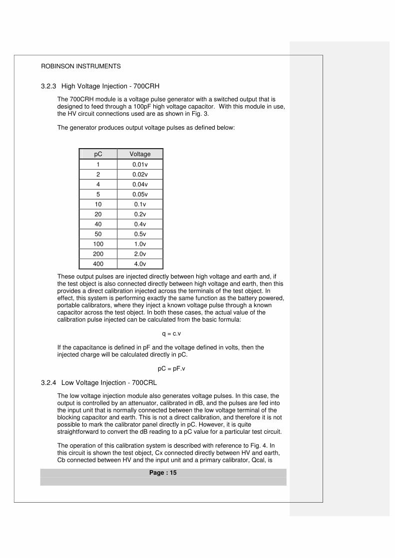
3.2.3 High Voltage Injection - 700CRH
The 700CRH module is a voltage pulse generator with a switched output that is designed to feed through a 100pF high voltage capacitor. With this module in use, the HV circuit connections used are as shown in Fig. 3.
The generator produces output voltage pulses as defined below:
pC Voltage
1 0.01v
2 0.02v
4 0.04v
5 0.05v
10 0.1v
20 0.2v
40 0.4v
50 0.5v
100 1.0v
200 2.0v
400 4.0v
These output pulses are injected directly between high voltage and earth and, if the test object is also connected directly between high voltage and earth, then this provides a direct calibration injected across the terminals of the test object. In effect, this system is performing exactly the same function as the battery powered, portable calibrators, where they inject a known voltage pulse through a known capacitor across the test object. In both these cases, the actual value of the calibration pulse injected can be calculated from the basic formula:
q = c.v
If the capacitance is defined in pF and the voltage defined in volts, then the injected charge will be calculated directly in pC.
pC = pF.v
3.2.4 Low Voltage Injection - 700CRL
The low voltage injection module also generates voltage pulses. In this case, the output is controlled by an attenuator, calibrated in dB, and the pulses are fed into the input unit that is normally connected between the low voltage terminal of the blocking capacitor and earth. This is not a direct calibration, and therefore it is not possible to mark the calibrator panel directly in pC. However, it is quite straightforward to convert the dB reading to a pC value for a particular test circuit.
The operation of this calibration system is described with reference to Fig. 4. In this circuit is shown the test object, Cx connected directly between HV and earth, Cb connected between HV and the input unit and a primary calibrator, Qcal, is
ROBINSON INSTRUMENTS
Page : 16
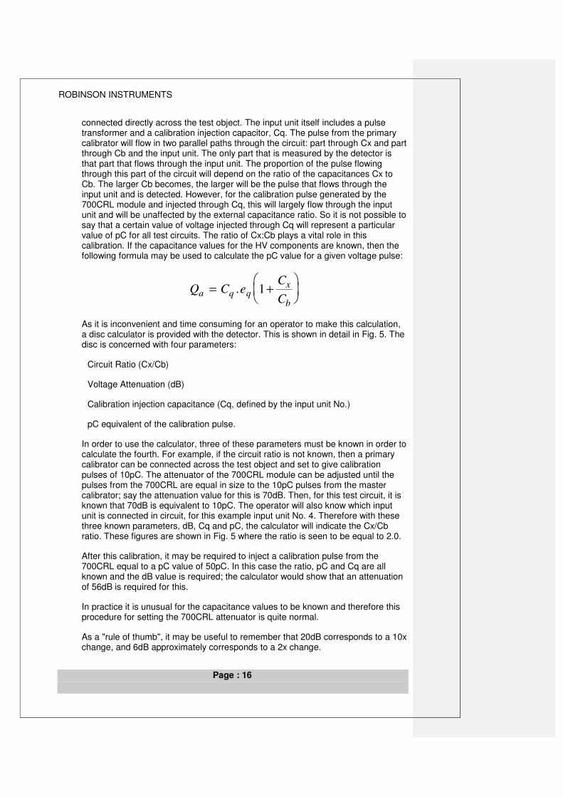
connected directly across the test object. The input unit itself includes a pulse transformer and a calibration injection capacitor, Cq. The pulse from the primary calibrator will flow in two parallel paths through the circuit: part through Cx and part through Cb and the input unit. The only part that is measured by the detector is that part that flows through the input unit. The proportion of the pulse flowing through this part of the circuit will depend on the ratio of the capacitances Cx to Cb. The larger Cb becomes, the larger will be the pulse that flows through the input unit and is detected. However, for the calibration pulse generated by the 700CRL module and injected through Cq, this will largely flow through the input unit and will be unaffected by the external capacitance ratio. So it is not possible to say that a certain value of voltage injected through Cq will represent a particular value of pC for all test circuits. The ratio of Cx:Cb plays a vital role in this calibration. If the capacitance values for the HV components are known, then the following formula may be used to calculate the pC value for a given voltage pulse:
Q C eC
Ca q q
x
b
= +
. 1
As it is inconvenient and time consuming for an operator to make this calculation, a disc calculator is provided with the detector. This is shown in detail in Fig. 5. The disc is concerned with four parameters:
Circuit Ratio (Cx/Cb)
Voltage Attenuation (dB)
Calibration injection capacitance (Cq, defined by the input unit No.)
pC equivalent of the calibration pulse.
In order to use the calculator, three of these parameters must be known in order to calculate the fourth. For example, if the circuit ratio is not known, then a primary calibrator can be connected across the test object and set to give calibration pulses of 10pC. The attenuator of the 700CRL module can be adjusted until the pulses from the 700CRL are equal in size to the 10pC pulses from the master calibrator; say the attenuation value for this is 70dB. Then, for this test circuit, it is known that 70dB is equivalent to 10pC. The operator will also know which input unit is connected in circuit, for this example input unit No. 4. Therefore with these three known parameters, dB, Cq and pC, the calculator will indicate the Cx/Cb ratio. These figures are shown in Fig. 5 where the ratio is seen to be equal to 2.0.
After this calibration, it may be required to inject a calibration pulse from the 700CRL equal to a pC value of 50pC. In this case the ratio, pC and Cq are all known and the dB value is required; the calculator would show that an attenuation of 56dB is required for this.
In practice it is unusual for the capacitance values to be known and therefore this procedure for setting the 700CRL attenuator is quite normal.
As a "rule of thumb", it may be useful to remember that 20dB corresponds to a 10x change, and 6dB approximately corresponds to a 2x change.
ROBINSON INSTRUMENTS
Page : 17
i.e. If 70dB = 10pC
Then 50dB = 100pC
90dB = 1pC
76dB = 5pC
64db = 20pC
3.2.5 DD5 Facilities
All detected pulses are shown on an oscilloscope display that is built into the instrument. The pulses are superimposed on an elliptical timebase so that all the cycle can be seen and the position of the discharge pulses within the cycle can be known. A typical display with discharge pulses is shown in Fig. 6. This figure also shows how the ellipse represents the alternating cycle.
An analogue Discharge Magnitude Meter is included that indicates the level of the largest detected pulse. This meter can be calibrated so as to read partial discharges directly in pC or with some simple correction factor (such as pC x 10). However, the meter will also respond to any interference noise present in the test circuit.
The window-gating unit can be used to eliminate the effect on the measurement of some stationary interference noise pulses. This is shown in Fig. 7 where two noise pulses exist and also some partial discharges are present. The window gates are adjusted and positioned by the operator to make measurements only in the areas shown shaded. The discharge magnitude meter does not measure any pulses outside these areas. In this example, the operator has positioned the gates correctly over that part of the cycle where the discharges are present and so the interference pulses are not measured.
The instrument also contains an HV meter that can be fed from a high voltage resistive divider. This can operate at voltages greater than 250kV with a suitable HV divider.
The detection impedance used with this detector is designed to give optimum sensitivity over a very wide range of test object capacitances. In order to achieve this over the range of capacitances from 6pF to 250uF, a series of 12 different measuring impedances are used. The ultimate sensitivity of any partial discharge measurement is inversely proportional to the square root of the test object capacitance.
i.e.. best sensitivity pCk
Cx∝
These 12 different input units all have the same basic components fitted, but the values in the different units vary as defined in Fig. 8. This Figure also shows the Ctot value that is the "tuning capacitance" of the given input unit. Each input unit is designed to operate best over a range of capacitance of about 8:1. This range is centered on a particular value of Ctot. Operation with values outside the defined range is not fatal but will reduce the achievable sensitivity and can affect the frequency response of the measurement system.
ROBINSON INSTRUMENTS
Page : 18
3.3 Measurement Sensitivity
The sensitivity of any Partial Discharge measurement circuit will depend on the impedance values of the items in the test circuit. Referring back to Fig 23 in Chapter 2, the pulse that flows through the input unit is only a part of the pulse that flows as a result of the partial discharge itself. To achieve good sensitivity, the part that flows through the input unit should be as large as possible. This will be achieved if the impedance of Cb is low compared to the impedance of Cx. This is shown in the graph in Fig 9 where the blocking capacitor is 1nF and the test object capacitance varies from less than 10pF to 10,000pF. There is only a small change in sensitivity when Cx is less than Cb but the sensitivity reduces significantly when Cx is increased so it is greater than Cb.
The choice of the blocking capacitor therefore is quite significant in defining the expected sensitivity that can be achieved from a given test circuit.
3.33.4 Bridge type Discharge Detectors.
The basic arrangement of a bridge type detector is shown in Fig. 10. The circuit can be balanced by adjustment to C2 and R1 so that any external interference present on the high voltage line can be minimised when seen on the detector, D. This attenuation can be achieved since external interference will be a common mode signal across the bridge. Any partial discharges generated in either HV component, Cx or Cy will not be attenuated since they represent a difference signal, not a common mode signal.
3.4.1 The Balanced Circuit and Bridge Techniques.
The Robinson Model 5 detector uses input units that can if required be connected in the "balanced mode". See Fig.11 This facility can be used when testing two similar test objects and again has the advantage that the effects of interference present in the high voltage supply line can be greatly reduced, as with a bridge type detector. In order to use a balanced circuit, it is necessary for the two samples to be very similar (if not identical) in capacitance. For either the balanced circuit or for a full bridge circuit the physical size of the test objects and the high voltage circuit should be relatively small and compact to prevent inductive pick-up of interference. This type of interference may be induced into and can circulate around the test circuit and so will not be attenuated by a bridge or balanced technique.
The practical applications of these techniques are a little limited and the best results will be obtained where two well-matched components can be tested together. This would include for example the testing of power factor correction capacitors. In this particular application the range of input units available gives the Robinson Model 5 a unique advantage since very large capacitances up to 500uF, may be tested in the balanced mode. A particular connection used by manufacturers of power factor correction capacitors is given in Fig 12. In this case four identical capacitors are used to make up a Cx2 that is nearly identical to Cx1 but each capacitor is exposed to only ½ the applied voltage. Any discharges then seen are almost certainly going to originate in Cx1.
ROBINSON INSTRUMENTS
Page : 19
3.43.5 Noise Rejecting Detectors.
In any discharge detection test, the achievable test sensitivity can be limited by the interference noise present at the test site. When factory testing to a defined test level, it will be imperative to reduce the noise so that successful tests can be performed to the sensitivity required. The Pulse Discrimination system is a modern noise rejecting discharge detector that is designed to reduce the effects of unwanted interference in practical testing conditions.
The interference may take the form of radio frequency transmissions, corona from adjacent circuits, thyristor pulse noise, switching transients or other pulse noise. The interference may enter the measurement circuit in a number of different ways, but chiefly by either conduction along the HV supply line or radiation directly onto either the HV line or test object itself. All these types of noise must be rejected to give the best achievable sensitivity.
The PDS system, (Model 803.2 or DDX8003) include various techniques for reducing or eliminating interference noise.
ROBINSON INSTRUMENTS
Page : 20
P A R T I A L D I S C H A R G E S
4 INTERFERENCE NOISE COUPLING
4.1 Introduction.
In all situations, but particularly in factory test environments, the test circuit may be exposed to electrical interference that can cause signals to flow in the test circuit that are much larger than the partial discharge pulses to be detected. So it is necessary either to eliminate the noise from the test circuit by careful electrical screening and good filtering or to use some other technique to allow the partial discharge pulses to be detected in the presence of electrical interference noise.
Noise may be detected as either:
• Continuous broadcast radio frequency signals (medium wave transmissions)
• Pulse interference from electrical machines
• Partial discharges from sources outside the test circuit
• Low frequency disturbances.
This noise may be introduced into the test circuit in several different ways.
4.2 Common Mode Noise.
Interference noise may be capacitively coupled into any part of the test circuit either from a noise source close to the test area (factory machines or wiring), or from a remote source (radio transmitter). See Fig 1
4.3 Induced Interference Noise
Interference currents can be induced into the test circuit and give rise to circulating noise signals. This effect is greatest if the impedance of the test circuit is low and the physical size of the loop formed by the test circuit is large. This effect is most common when testing drum lengths of power cable. See Fig. 2
4.4 Earth Induced Noise.
Noise may be coupled from the system earth in many ways; either into the HV measurement circuit, or by interaction with the signal leads coupling the discharge detector to the test circuit, for example. For earthing, it is important to consider both the test frequency performance of the earth connection where the earth may be required to carry large currents in the event of a fault; and the high frequency performance of the earth, as this connection forms part of the partial discharge measurement circuit; any stray inductance in the test connections can represent an impedance to the very fast partial discharge pulses. See Fig. 3
ROBINSON INSTRUMENTS
Page : 21
4.5 Noise Coupled from the Supply Line
Noise can be introduced via the HV power supply. This noise is most often coupled via stray capacitance across windings rather than via conventional transformer action. See Fig. 4
These notes summarize the main noise coupling mechanisms, but others may also occur in certain cases.
4.6 Noise Minimisation and Test Circuit Arrangement
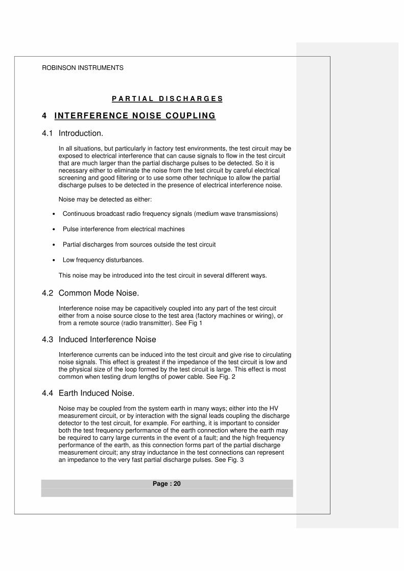
The basic practical aim is to minimise the levels of interference currents that flow in the Input Unit, while retaining the sensitivity to any partial discharges within the test object. The most important parts of the test circuit for partial discharge testing are shown in Fig. 6. Figs 7 – 13 give particular comments about these points. Perhaps the most important part is the loop formed by the test object and the blocking capacitor; it is in this loop that any partial discharge currents from the test object will flow. This loop should be kept as small as possible so as to reduce the amount of coupling that gives rise to interference currents (see Para 4.3)
The exposed length of the incoming HV connection to this test loop should also be kept short so as to reduce the “antenna” effect of the HV line. This should help to control the noise coupled through the air that would cause currents to flow. (See Para 4.2). An HV filter may be used to isolate the test loop from the power supply components and in this case the filter should be placed close to the test circuit for the same reason; a longer connection back from the filter to the power supply is less critical.
As with any sensitive electrical measurement, the earthing connections are particularly important. This is often difficult to control with an extended measurement circuit that bridges from the HV test area back into the control room environment. It is also important to consider that the earths in this environment must primarily satisfy safety requirements that are related to the power frequency operation of the system, but for the partial discharge measurement, it is the higher frequency response of the earth system connections that will affect operation. Very small levels of stray inductance in the earth connections can have an effect on the system sensitivity and earth coupled noise. For this reason, it is normal practice to make use of either insulated flat section copper strip or braid, or a multi-stranded and insulated circular section cable for earth connections. It is also normal to install a separate earth system for the HV test area that can be isolated from the main factory / building earth.
It is also essential to use good diameter conductors for the HV connections so as to avoid corona effects and to ensure that all contacts in the circuit are well made so as to avoid possible contact discharges in the system.
ROBINSON INSTRUMENTS
Page : 22
P A R T I A L D I S C H A R G E S
5 NOISE REJECTION PRINCIPLES
5.1 Introduction.
The most common problem found when making partial discharge measurements in practice is external electrical interference noise. In a factory environment, this noise is often caused by thyristor-controlled machines operating in the vicinity of the test area, or switching transients or broadcast radio frequency signals. The Pulse Discrimination System has been developed so that users can make tests in the presence of this noise without the need to screen fully the test area and to filter electrical supplies entering the area. This section describes the instrument system and how it makes this noise rejection.
4.25.2 Pulse Discrimination System.
There are now two instruments that include the Pulse Discrimination facilities:
803.2 Analogue PD detector with PDS
DDX8003 Digital PD detector with PDS
The general principles described in this chapter apply to both instruments.
5.2.1 External pulse rejection.
The basic test circuit used by the pulse discrimination system is shown in Fig 1. The two input units shown as A and B contain pulse detection impedance elements and active pulse amplifiers. All signals detected are then fed to the main discharge detector instrument for processing and display.
Where pulse interference exists on the HV line, then pulse currents will flow to earth through both the test object and Cb. These currents will flow in parallel giving rise to pulses of equal polarity in the two input units shown. If a partial discharge occurs in the test object however, then the pulses flowing as a result of this will follow the path shown in Fig 1 giving rise to pulses of opposite polarity in the two input units. The pulse polarity information is then used to determine the origin of the detected pulse; pulses having opposite polarities being defined as originating within the test circuit, (Internal discharge) while pulses having the same polarity will have originated outside the test circuit, (External discharge). In this way unwanted (External) interference pulses may be electronically rejected allowing the operator to observe only those pulses of interest.
For the system to recognise an Internal partial discharge three conditions must be satisfied:
1. The pulse must exist on both channels A & B and must be greater in amplitude than the reference level on both channels;
2. The pulses on channels A & B must exist at the same time:
3. The pulses on channels A & B must have opposite polarities.
ROBINSON INSTRUMENTS
Page : 23
When these conditions are satisfied, then the instrument generates a signal that is used inside the instrument to pass the discharge pulse to the display and meter. So that it is easier to see on the display it is stretched to a length of about 20 us
4.2.25.2.2 Calibration
In order to calibrate the system, it is necessary to inject a pulse into the test circuit so that the calibration pulses flow around the circuit in a similar manner to the internal discharges themselves. If this did not happen, then the Pulse Discrimination System would reject its’ own calibration pulses!
This is achieved using the connection shown in Fig. 2.
The system requires a portable primary calibrator to be connected across the test object. These calibration pulses flow as indicated and are seen by the PDS an “INTERNAL” pulses. A secondary calibration pulse is then injected from the instruments’ calibrator into the calibration unit that is connected as shown between the two input units. These secondary calibration pulses are coupled through a pulse transformer so that they also flow through the two input units and generate “INTERNAL” pulses. The calibrator in the instrument can then be adjusted so that the pulses injected through the coupling unit are equal in size to the primary calibration pulses which are injected, as always, across the terminals of the test object. The instruments’ calibrator is then adjusted so that the calibrator-displayed value is equal to the value injected by the primary calibrator. The instruments’ calibrator can then be used to inject valid secondary calibration pulses while the HV is applied to the test circuit.
4.2.35.2.3 Inductively Coupled Pulse Rejection.
If the pulse interference is inductively coupled into and circulates around the test circuit, it may not be rejected by the basic Pulse Discrimination function. However, such pulses may be rejected by use of the Transient Suppressor facility. This is shown in Fig. 3 as a third input unit, N, to which is connected a simple antenna. When used, this is situated in the vicinity of the test object so that the antenna may detect the same radiated transient pulses as the test object itself. The electronics of the system will then reject all pulses in the measuring circuit that occur at the same time as a pulse is detected on the antenna. This simply assumes that partial discharge pulses that are generated within the test circuit will be detected by the two measuring input units only, while radiated interference pulses will be detected by both the antenna and the two test circuit input units.
4.2.45.2.4 Radio Frequency Interference.
Radio frequency transmission can also limit the effective sensitivity of a partial discharge measurement in an unscreened environment. This effect can be electronically reduced by means of a radio frequency suppressor. The radio frequency signals that will flow are indicated in Fig. 4. The two input units, A and B, will both detect RF signals that are in phase with each other but will generally have different amplitudes. The two signals may then be balanced and subtracted in analogue form so as to minimise the effect of the RF interference. Since the partial discharges of interest will give rise to pulses having opposite polarities, then this subtraction technique will have the effect of actually increasing their observed amplitude.
ROBINSON INSTRUMENTS
Page : 24
4.35.3 Naturally Screened components.
When testing installed plant or equipment in a factory environment that is enclosed inside a large natural metal screen, e.g. power cable or SF6 insulated switchgear, the test object may be bonded to earth and thus the circuit configuration shown in Fig 1 will not be applicable. To overcome this, a modification to the basic test circuit has been implemented that allows the two input units, A and B to be located at the high voltage terminals of both the test object and the blocking capacitor, Cb. Exactly the same principles of operation will be seen to apply in this case as in Fig. 1 where LV input units were used. This circuit arrangement is shown in Fig 5 and the path followed by a partial discharge occurring in the test object is again given. The inductor marked ‘L’ is often included to give added attenuation to unwanted common mode noise existing on the HV line. To achieve this inversion of the test circuit in practice, it is necessary to overcome certain problems. Firstly, a power supply is required to operate the active amplifiers included inside the two input units; this is provided by means of rechargeable batteries. Secondly, the detected signals must be transmitted from high voltage down to the discharge detector that remains at ground potential; this is achieved by use of fibre optic cables that provide the required isolation and act as the signal link. Thirdly, the unit at high voltage must be controlled from the discharge detector and again this is achieved by means of a separate fibre optic link that carries coded control information up to the high voltage. Fibre optic cables are available that give excellent isolation and such a system has been successfully operated at voltages in excess of 500 kV. It is also necessary to calibrate the instrument and a remote calibrator has been included inside this high voltage unit that is again controlled via the same fibre optic link. (Type 906 HV Input Unit only.)
The fibre optic cables used will allow transmission over distances of up to 50 m thus enabling the discharge detector to be sited at some safe distance from the test area. In some instances, customers have requested that the fibre optic cables should be taken directly from the High Voltage section of the Input Unit to the control room. This has the advantage that there need be no electrical cables linking the PDS with the test circuit.
5.3.1 Calibration with HV Input Unit
When the High Voltage Input Unit is used, then a different technique is required to inject “INTERNAL” calibration pulses into the test circuit. This is achieved in two different ways.
4.3.1.15.3.1.1 Calibration with 806 HV Input Unit.
The method employed with the older HV Input Units, type 806, is given in Fig. 6. This uses a high voltage injection capacitor that is connected directly across the test object. The calibration pulses are again most often coupled through a pulse isolation transformer
4.3.1.25.3.1.2 Calibration with 906 HV Input Unit.
A different technique is employed with the more recent 906 models that eliminate the need for a high voltage injection capacitor. This is shown in Fig. 7. In this case the actual calibration pulse generator itself is housed inside the HV section of the 906, but is controlled, via the fibre optic link, from the PDS instrument. The electrical connection inside the 906 is effectively the same as the 803LV
ROBINSON INSTRUMENTS
Page : 25
connection (Fig. 2), but inverted. The calibration pulses are again coupled through a pulse transformer and injected, as shown, between the input unit terminals. This technique does not give a primary calibration, but must be used in conjunction with a portable primary calibrator.
4.45.4 Two Component Testing.
Another feature of the system is that as well as being able to discriminate between Internal and External pulses, the system can also define from which of the two HV components in the test circuit, an Internal discharge comes. This feature can be particularly useful when two test objects are connected in circuit without a blocking capacitor. If a discharge is seen during such a test, then the instrument can immediately say which is the faulty component. The basic pulse flows with this connection are shown in Fig. 8.
ROBINSON INSTRUMENTS
Page : 26
P A R T I A L D I S C H A R G E S
6 GENERAL TESTING APPLICATIONS
6.1 Introduction.
Partial Discharge testing can be applied to all types of high voltage components. This section discusses some of these applications.
6.2 Transformer Testing
This section gives some general comments relating to the testing of single and three phase power transformers. Partial discharge tests on power transformers are normally made by "self-energising" the test transformer by providing a variable voltage input to the LV side and hence inducing a high voltage in the HV winding which itself acts as the test voltage.
6.2.1 Tests without Bushing Taps.
Where the test transformer does not have bushing taps provided, as is common with lower voltage transformers, see Fig. 1, then it is necessary to connect a blocking capacitor to the HV phase output or outputs. This capacitor is normally of 1000 pF and will be rated to the maximum test voltage that the user expects to apply. With a three-phase transformer, three such capacitors can be connected, one to each phase. The Discharge Detector input units or coupling boxes are connected in series with each of these three capacitors at their LV ends. If preferred (with a three phase transformer), then only one blocking capacitor need be used, but this must be connected to each phase in turn thereby increasing the total testing time. Generally for site testing however, this method would be preferred where setting up time is more important than testing time, and generally the engineer will wish to transport the minimum number of parts to site for the test.
6.2.2 Tests with Bushing Taps.
For higher voltage rated transformers it is common that the transformer output bushings will be fitted with capacitive bushing taps. In this case, separate blocking capacitors are not required as the input unit or units may be connected to the bushing taps and any partial discharges are coupled into the input units via the capacitance of the bushings, see Fig. 2. In all operational respects, both of these alternative connections will operate similarly. Again, the phases may be tested sequentially using just one input unit if preferred.
6.2.3 Voltage Measurement.
When using a type 700 discharge detector, the output voltage on the transformer is monitored using a voltmeter resistor that may be connected to any one of the three output phases, and it will then indicate on the discharge detector the voltage induced between the phase and earth. Should the winding connection be delta, then a correction must be made for this difference.
ROBINSON INSTRUMENTS
Page : 27
If a DDX7000 is used for this application, then a voltage and phase reference signal will be available from each of the coupling boxes that is connected to each phase winding. The phase reference information provided from the coupling box will be true in all cases, and the voltage measurement will also be true if a standard 1000pF capacitor is used for coupling, but will not be true if the signal is taken from the bushing tap. The DDX7000 allows a voltage calibration to be made so that correct readings can be obtained if a simple on-site calibration procedure is followed.
6.2.4 Three Phase Measurements.
With either the 700 or DDX7000 systems, the operator can make a separate partial discharge measurement on each of the three phases by use of a Three-Way Switch Box. This selects which of the three input units feeds its output to the discharge detector. Thus the operator can switch between phases without disconnecting the voltage supply. This is shown in Fig. 3
6.2.5 Variable Supply Frequency Testing.
In order to achieve the required test voltage for the finished transformer, which in a factory test will be significantly greater than the normal operating voltage, it will be necessary to increase the primary input voltage to above its normal level. If the tests are performed at the normal supply frequency, 50 Hz or 60 Hz, then the maximum test voltage that can be impressed on the winding will be limited to a small, maybe 10%, overvoltage. (For many site-testing applications, this will be quite adequate). Where this is a problem, it can be avoided by increasing the frequency of the supply voltage, often to between 150 Hz and 400 Hz. This increase of frequency can avoid effects of core saturation. The supply at this higher test frequency is often derived from a Motor - Generator set. In this the motor is operated from the local mains supply and the generator is controlled to give the required output frequency and voltage. It is particularly important with this application that the output from the generator is well filtered so that the higher order harmonics do not affect the discharge detector measurements. It is possible to specify with the 700 (or select with the DDX7000) particular amplifier characteristics that are less sensitive to these interfering frequencies.
In this situation it is also important that the discharge detector may be synchronised with the test supply frequency. With a type 700 detector this is achieved by feeding a sample of the frequency to the detector that will synchronise the elliptical display to the test frequency while the instrument itself is powered from the local mains supply. The DDX7000 will automatically synchronise with the voltage measurement signal provided by the coupling box with no additional connections or adjustments to be made.
6.2.6 Bushing Testing.
Unless the bushing has been completely removed from its host plant, then any voltage applied to the bushing will also energise this host plant, which may also generate partial discharge! However, if a bushing tap is available, then a good knowledge of the discharge test circuit and a careful observation of the discharge detector trace, can help to define if any discharges seen actually come from the bushing or from the host plant.
ROBINSON INSTRUMENTS
Page : 28
A single input unit should be connected at the bushing tap between this point and earth. Either a voltmeter resistor should be connected to the HV line, or some other means employed to define which part of the ellipse display represents the positive half-cycle and which the negative. This is most important for the following interpretation. With this connection and this information, the discharge test can be performed.
If discharges are seen that are POSITIVE pulses occurring in the POSITIVE half-cycle, and NEGATIVE pulses in the NEGATIVE half-cycle, then these discharges exist in the BUSHING.
If discharges are seen that are NEGATIVE pulses occurring in the POSITIVE half-cycle, and POSITIVE pulses in the NEGATIVE half-cycle, then these discharges do NOT exist in the BUSHING.
This is shown in Fig. 4
6.3 Rotating Machines
Modern Rotating machines will generally use cast resin as insulation for the stator bars, while older machines had used mica based insulation. Mica insulation is formed in layers and this will inherently cause small cavities between the overlapping layers that would lead to partial discharges within the insulation. Mica itself is quite resistant to partial discharge activity but more damage could be caused by the very large discharge pulses that may exist at the end of the windings where they emerge from the slots, or discharges existing in any gaps between the bars themselves and the walls of the slots in the stator. In either case, resin or mica insulation, larger levels of partial discharge activity can be expected with rotating machines than with other types of HV component.
Tests can be made on the stator windings of rotating machines. In this case it is normal to test the main insulation between the winding and the machine frame. This test will use the conventional test circuit.
Where it is possible to isolate windings at the star point, then a test can be connected that will also verify the inter-turn insulation between windings
Tests can be performed in one of two ways:
• Voltage can be applied to all phase windings together with respect to the machine frame (earth); See Fig. 5.
• Voltage can be applied to one particular phase winding with respect to the other two phases and to the frame. This test can only be performed if the phase interconnections can be separated for test. See Fig. 6.
6.3.1 Discharge Pulse Superposition
Generally, partial discharge detectors will make a measurement of individual partial discharge pulse amplitudes and the recorded pC value for a test will be related to the value of the largest individual discharge. The repetition rate of discharge pulses from most test objects is sufficiently slow so that the probability of more than one discharge pulse occurring at the same instant within the component is small. This assumption does not apply with rotating machines. With
ROBINSON INSTRUMENTS
Page : 29
Mica insulation, there are likely to be many different sites within the system each having its’ own independent partial discharge sequence. The possibility of discharges from different sites now occurring at the same instant in time becomes quite high with the result that the pC level recorded by the discharge detector can be the sum of some different discharges added together.
This is not necessarily a problem for the measurement since any measurement made on a rotating machine will only be compared with another measurement made either on the same or a different rotating machine. This is particularly true when making routine measurements on specific machines where measurements obtained are compared with measurements previously obtained on the same machine.
6.4 General components
Special care must be taken when testing low capacitance test objects, since the value of stray capacitance and transformer output capacitance may be of the same order as the test object and coupling capacitor. In this case, a significant portion of the partial discharge pulse may flow through the stray capacitance and so reduce the test sensitivity. This effect can be avoided by the use of a series inductor in the HV line as shown in Fig. 7.
Other components, apart from power cables, can generally be considered as a capacitance for the purpose of partial discharge testing. Where the test is made inside a screened room and noise is not a problem, then the conventional connection using the type 700, or DDX7000 detectors can be used; where interference noise does affect the testing, then the connection using the pulse discrimination system can be used. In certain cases, the PDS system with the high voltage input unit connection will give the best results. This may be important when testing small sections of GIS where the capacitance values may be low. Fig. 8 shows such a connection and highlights the most sensitive part of the test circuit, i.e. the connection between the test object and the coupling capacitor where the partial discharge that are measured will flow.
One application of the PDS system is shown in Fig. 9 where a three-phase section of GIS is under test. The electrical equivalent of this is given in Fig. 10.
ROBINSON INSTRUMENTS
Page : 30
P A R T I A L D I S C H A R G E S
7 INTERPRETATION OF DISCHARGES
7.1 General.
The pattern of Partial Discharges shown of the elliptical display can give some helpful indication as to the type of defect inside the item being tested. Many typical patterns are shown in the CIGRE document "Recognition of Discharges". Some of these patterns are very distinctive and can be quite simple to identify, but many others in practice are not as easy.
7.2 Noise and Disturbances.
Possibly the first and most important point to confirm is that the pattern seen does come from the test object and is not interference noise.
If the pattern is present before the voltage is switched on, then it must necessarily be external interference.
If the pattern appears as soon as the main contactor to the test power supply is closed before any voltage is applied, then this also is likely to be some form of interference. (Pattern "J" in the CIGRE book can however start at very low voltages; spark gap operating).
In general, any pattern that is voltage dependent, i.e. appears at a certain voltage and normally increases in activity with voltage, is most likely to be some form of discharge associated with the HV circuit. Exceptions to this can arise with magnetic saturation in transformer or reactor cores, (case "Q"). Here, a disturbance can occur at a particular applied voltage and the size and nature of this disturbance can change as the voltage is increased further. The general behavior of the disturbance is quite different from a genuine partial discharge however.
7.3 Partial Discharges.
Partial discharges either inside or on the surface of insulation will normally occur between the voltage zeroes and the voltage peaks and will show a high degree of variability in position and amplitude on successive cycles. Discharges as in pattern "A" however may be rather more stable and repeatable.
The most useful points to note concerning discharge behavior include:
� What part of the cycle do discharges occur on?
� Are the two half cycles similar in discharge numbers and magnitude? If there is a difference, can this be defined?
� How do the discharges change with increase in applied voltage?
ROBINSON INSTRUMENTS
Page : 31
� Do the discharges change with time when the voltage remains constant?
� Is the discharge pattern constant?
Among the most common form of unwanted partial discharge are surface discharges that are characterised as pattern "H". These can occur on cable terminations, bushings and cast resin components and can often be avoided by careful cleaning of the surface; cable terminations can at times prove more difficult to resolve!
7.4 Identification of type of Discharge.
When interpreting patterns the following points should be borne in mind:
(a) The ellipse is always written in a clockwise direction.
(b) The markers always occur at the zeros of the test voltage waveform. (This corresponds to the maximum current when capacitive specimens are being tested).
(c) The negative marker pulse indicates when the test voltage is changing from positive to negative polarity.
(d) The positive marker pulse indicates when the test voltage is changing from negative to positive polarity.
A typical discharge pattern from most types of insulation is shown in Case A. In this pattern discharges appear on the quadrants of the ellipse that correspond to the test voltage rising from zero to maximum either positively or negatively. The discharges usually start near the peaks of the test voltage but spread towards the zeros as the test voltage is increased above inception. The number and magnitude of discharges on the opposing half cycles are approximately the same.
A typical discharge pattern from a void bounded on one side by insulation and on the other side by a conductor is shown in Case G. This type of discharge is commonly produced in a polythene-insulated cable when the insulation has not adhered to the conductor properly. The discharge is distinguished by the large number of small discharges on the negative half cycle and the smaller number of larger discharges on the positive half cycle.
Case L. shows the pattern produced by a discharge from a sharp point into air. This is usually produced by a sharp point on the high voltage connections of the test circuit and may be distinguished by the fact that it only occurs around the negative peak of the test waveform. If only one point is involved all the discharge pulses will be of the same magnitude, and increase of test voltage will only increase the number of pulses but not the magnitude.
Contact discharges are shown in Case N. and may be distinguished by the characteristic shape of their pattern and their position at the current peaks of the test waveform.
ROBINSON INSTRUMENTS
Page : 32
P A R T I A L D I S C H A R G E S
8 DIGITAL PARTIAL DISCHARGE DETECTION
8.1 General
All modern techniques of partial discharge detection and measurement are based around the use of digital instruments. The partial discharge signals are detected in the high voltage circuit using exactly the same connections as with an analogue system. Connections previously described may all be used.
There can be different techniques used to capture the fast discharge signals digitally, but the modern specifications (IEC60270) are starting to put some definitions upon these techniques to ensure comparability.
When the signals are digitised they can be displayed in many different forms on any type of computer monitor display. The signals can also be stored in computer memory for later retrieval or analysis or can be recorded on paper if a standard printer is connected to the instrument.
8.2 DDX7000
This instrument is the digital successor to the Model 5, type 700 analogue detector. The DDX preserves the features of the 700 (selectable bandwidth amplifier; gating windows; discharge metering; HV metering; fast bi-polar pulse displays etc.) as well as providing additional features given by the digital system such as automatic pC calibration of the test circuit; ability to record and print out pulse displays and test reports etc.
The amplifiers used are digitally controlled and that fact ensures that after the test circuit is calibrated, the instrument and the metering remain in calibration even if the amplifier gain setting is changed. This is a most useful feature in practice.
8.2.1 DDX Features
� Easily grouped controls for routine production testing
� Clean and clear digital display
� Fast screen updating to generate “Live” feel to the display
� Automatic calibration of test circuit
� Direct measurement of discharge in pC and also of Applied HV
� Simple generation of test reports
� DDX will couple to any Windows© compatible printer (monochrome or
colour)
� Compatible with many different signal input sources.

ROBINSON INSTRUMENTS
Page : 33
8.3 DDX8003
This instrument includes all the features given in the DDX7000 but also provides the Pulse Discrimination feature previously included in the model 803. This unit can operate with either the low voltage input units or with the High Voltage unit type 906.
ROBINSON INSTRUMENTS
Page : 34
APPENDIX A
9 NOISE SUPPRESSION TECHNIQUES
8.19.1 Introduction:
Partial Discharge (PD) detection is a sensitive electrical measurement.
Most practical applications require that a quantitative assessment of the PD is made that allows a measurement of the discharge pulses in picocoulomb, pC
In order to achieve this, the frequency bandwidth limits of the measuring instruments used are defined by international standards.
This bandwidth and sensitivity will cause partial discharge detection instruments to be sensitive to certain forms of interference noise as well as to genuine partial discharge pulses of interest.
8.29.2 Interference Noise Types:
The interference noise encountered may include the following types:
� Harmonic or low frequency noise that is generally synchronised to the HV supply frequency;
� Continuous broadcast a.m. (amplitude modulated) radio transmissions or other continuous radiated signals, normally at a frequency below 1MHz;
� Repetitive pulse interference (often caused by thyristor or diode switching) that occurs at generally the same phase position in successive cycles of the applied ac high voltage;
� Truly random pulse noise that may be caused by switching operations (e.g. overhead cranes, thermostatic controls etc.);
� Unwanted partial discharge signals NOT generated in the test component (e.g. discharges in the HV power supply components or adjacent test circuits);
� Quasi white noise that may be related to system earth connections.
9.3 Test Applications:
The types of noise that are most important for a particular installation will largely depend on the type and location of that installation:
� Factory / Laboratory tests made inside a screened room (Faraday cage);
� Factory / Laboratory tests made without a screened room;
� Testing carried out on installed equipment in the field.
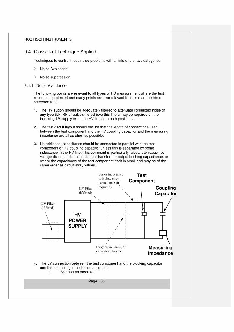
ROBINSON INSTRUMENTS
Page : 35
9.4 Classes of Technique Applied:
Techniques to control these noise problems will fall into one of two categories:
� Noise Avoidance;
� Noise suppression.
9.4.1 Noise Avoidance
The following points are relevant to all types of PD measurement where the test circuit is unprotected and many points are also relevant to tests made inside a screened room.
1. The HV supply should be adequately filtered to attenuate conducted noise of any type (LF, RF or pulse). To achieve this filters may be required on the incoming LV supply or on the HV line or in both positions.
2. The test circuit layout should ensure that the length of connections used between the test component and the HV coupling capacitor and the measuring impedance are all as short as possible.
3. No additional capacitance should be connected in parallel with the test component or HV coupling capacitor unless this is separated by some inductance in the HV line. This comment is particularly relevant to capacitive voltage dividers, filter capacitors or transformer output bushing capacitance, or where the capacitance of the test component itself is small and may be of the same order as circuit stray values.
HVPOWERSUPPLY
CouplingCapacitor
TestComponent
MeasuringImpedance
LV Filter
(if fitted)
HV Filter
(if fitted)
Stray capacitance, or
capacitive divider
Series inductance
to isolate stray
capacitance (if
required)
4. The LV connection between the test component and the blocking capacitor and the measuring impedance should be: a) As short as possible;
ROBINSON INSTRUMENTS
Page : 36
b) Made using a low inductance connection such as flat copper strip, flat section braid or heavy round section insulated welding cable
5. Connection made to the input side of the measuring impedance should not normally be made using a screened cable unless it can be shown that this does specifically reduce noise. A screened cable at this point will represent an unwanted capacitance directly across the measuring impedance and this will tend to reduce the sensitivity of the measuring system.
6. All high voltage connections used should be of round cross section having a diameter suitable for the level of voltage to be applied. This requirement is to ensure that no corona discharge is generated in these connections.
7. No cables or conductors of any kind (earth connections, signal cables, measurement cables or power leads) should pass through the loop that is formed by the test component and the coupling capacitor.
8. All metallic objects in the vicinity of the high voltage components or HV line should either be connected to earth or should be removed. Un-earthed objects within the HV field may cause unwanted partial discharges (floating objects)
9. Some forms of electrical interference are directional and such noise may be reduced if it is possible to rotate or change the physical orientation of the test circuit.
10. As in all sensitive electrical measuring system, the signal earth connections are a very important factor in controlling system noise. For a HV PD test this earthing requirement can be complicated by the additional requirement that the system must ensure a safe and secure connection to earth in the event of a breakdown in the HV test circuit. Both these requirements can usually be satisfied if a single point earth connection is adopted. Some care may be required to ensure that the PD signal and other measurement connections do not inadvertently cause an earth loop. This factor is of particular importance when testing inside a screened room; the integrity of the screening may be badly affected by the presence of unwanted, avoidable earth connections.
11. Non-Inductive Link. Interference noise may be coupled into a measurement circuit by electromagnetic induction. This effect is typified by a situation where an interference noise is flowing as a current in the vicinity of the test circuit. For example, this current may be in a power cable or earth cable or in a metallic part of the building structure. The test circuit effectively forms a loop comprising the test component, the coupling capacitor and the measuring impedance. Where the test component itself is physically large, the loop formed by the test circuit is also likely to become large. The cross-sectional area of this loop is an important factor in defining the extent of this coupling; the high frequency impedance of the circuit loop is another important factor. Both these factors combine when testing drums of HV cable where the impedances are low and the physical loop area is usually large. Thus these circuits are particularly prone to this electromagnetically induced interference. The Non-Inductive Link (NIL) is a circuit technique that can reduce the amount of noise coupled into the test circuit in this way. The principle is demonstrated in the drawing below:
ROBINSON INSTRUMENTS
Page : 37
HVinfeed
CouplingCapacitor
MeasuringImpedance
Non-InductiveLink [NIL]
SeriesInductor
Main Earthconnection
Z-PLANE
Y-PLANE
X-PLANE The NIL frame makes the electrical connection between the screen of the HV cable under test and the LV end of the coupling capacitor, both of which are at earth potential. (This example is drawn with the measuring impedance located in the high voltage side of the blocking capacitor). Any noise that is electromagnetically coupled in the X-plane sees the earth connection in parallel with the HV connection that effectively gives a loop having a zero area. This can significantly reduce any electromagnetically induced noise in this plane. Any noise similarly coupled in either the Y- or Z-planes sees two loops formed by the symmetrical halves of the NIL on either side of the cable / capacitor HV connection. Noise currents will be induced equally in these two halves. These currents will both flow in the same sense (clockwise or anti-clockwise) and will give rise to noise currents in the central common limb that flow in opposite directions. The measuring impedance is connected in this central, common limb and so natural cancellation of these noise currents will take place. Thus, noise coupled in any plane can be reduced.
12. Screening. Effective screening of the test area, in conjunction with good filtering and a good earthing system, can be used to provide a very high degree of attenuation to noise present in the test environment. The normal precautions to avoid unwanted PD from within the test circuit itself will still apply and good circuit connections will still offer the best measurement sensitivity. Ideally, all parts of the test circuit and HV power supply should be contained within this room but very often space limitations and economic restraints will require that the room size is minimised and some power supply components and control parts may then be located outside the room. In this case particular care may be required with earthing, screening and filtering of signal, power and measurement connections that are required to cross the screened room boundary. This is to ensure that these connections do not themselves carry noise into the screened area.

ROBINSON INSTRUMENTS
Page : 38
9.4.2 NOISE ELIMINATION
Techniques for noise elimination must be chosen to suit the type of noise encountered. Different testing situations are likely to be exposed to different noise profiles.
1. Screened Room: A well-filtered, well-constructed and well-connected screened room should not allow noise into the PD test environment.
2. Unscreened laboratory / factory test area: These environments may be exposed to many types of interference noise including pulse noise (thyristor controls etc.) and RF noise.
3. Installed equipment on-site: RF noise is the most commonly experienced noise in these situations.
The techniques for noise elimination are used where noise avoidance is either not effective or not practical. They may call for some variation in the basic test circuit configuration and may include some forms of signal processing, either on-line or off-line.
8.4.2.19.4.2.1 Signal Gating.
This technique is used in some PD detection instruments to eliminate certain pulse interference from discharge measurements. It can be applied to a conventional PD test circuit connection. It makes use of an electronic switch that is synchronised to the test supply frequency and will eliminate certain parts of the supply cycle where interference pulses exist. The function may be manually adjusted or automatic.
With manual control, the user will adjust the phase position of the gates so that fixed interference pulses can be excluded from the measurements.
An automatic system may use an antenna to detect interference pulses and then control the gating switch automatically so that these specific positions of the cycle, where interference pulses exist, can be excluded from the measurements.
8.4.2.29.4.2.2 Bridge Methods
This testing technique may be used to attenuate noise signals (both pulse noise and continuous signals such as RF) that may be present on the HV supply line. The measurement circuit, comprising the test component and the coupling capacitor are connected as a bridge with adjustable balance components connected between these two parts and earth. (Sometimes the coupling capacitor may be replaced by a second similar test component.)
ROBINSON INSTRUMENTS
Page : 39
Coupling
Capacitor
or 2nd test
component
Test
Component
Measur ing
Impedance
LV Filter
(if fitted)
HV Filter
(if fitted)
Series inductance
to isolate stray
capacitance (if
required)
Bridge PD Detector
Adjustable
Balance
Components
RC
HVPOWERSUPPLY
In this connection, the measuring impedance is connected across the low voltage arms of the bridge as a detector. The bridge balance controls can then be adjusted to reduce the interference noise signals to a minimum. Any PD generated in either the test component or the coupling capacitor will circulate the PD signals around the bridge and will so cause an out-of-balance signal across the measuring impedance and these pulses will then be measured by the system.
This technique is most effective where both the high voltage components in the bridge circuit are identical and the interference is mainly RF. However the balancing controls will allow a useful attenuation of common mode noise in more general situations.
8.4.2.39.4.2.3 Pulse Discrimination Method.
This is an on-line technique used to eliminate pulse interference noise. It uses a test connection incorporating two identical measuring impedances, one connected in series with the test component and the second in series with the coupling capacitor (or second test component).
Any common mode noise pulses will cause pulse currents to flow to ground in parallel through both high voltage components. These pulse currents will give co-incident pulse signals in the two measuring impedances having the same polarity of pulse.
ROBINSON INSTRUMENTS
Page : 40
Coupling
Capacitor
or 2nd test
component
Test
Component
Measur ing
Impedance 1
LV Filter
(if fitted)
HV Filter
(if fitted)
HV
POWERSUPPLY
Measuring
Impedance 2
PD from
Test
Component
Interference Noise
Pulse
Any PD in either test component will cause pulse currents that circulate in the test circuit and will give co-incident pulse signals in the two measuring impedances that have opposite pulse polarities.
The discharge detector will define the polarity of each pulse signal detected and will compare the polarity of these pulses from the two measuring impedances. If co-incident pulses are detected in the two measuring impedances that have the same polarity, then these pulses are eliminated from the measurement. Where co-incident pulses are detected that have opposite polarities, these are accepted as PD from the test circuit and are measured.


![Training Pd Blowers [Compatibility Mode]](https://img.pdfslide.net/doc/110x75/577c810a1a28abe054ab3b83/training-pd-blowers-compatibility-mode.jpg)