Embed Size (px)
Citation preview
Crystal characterization andcrystal filter design
An overview of tools and techniquesNick Kennedy, WA5BDUJoplin, MO April 26, 2008
Goals of this presentation
• Describe some methods of crystal characterization (e.g.measurement of parameters), the hardware required,and the measurement techniques used
• Discuss and describe some available filter designsoftware (generally free) and its use, including softwareto analyze proposed designs before building
• Define some common terms and discuss tips andprecautions for filter design and the merits of variouspopular designs
• Convince the typical ham builder that crystal filter designis neither too expensive nor too complex for him toattempt
From impossible to easy – some history• 1960s – No PC design software. No PCs either! And no handheld
calculators. Prevailing crystal filter design is a lattice or half latticeusing custom ordered crystals on different frequencies, tooexpensive for the typical ham. Also, no signal generators with 1 Hzreadout and enough stability for measuring crystal parameters.
• 1976+ RGSB’s Technical Topics reports on F6BQP’s experimentswith ladder filters utilizing crystals all on the same frequency.Crystal parameters aren’t measured, but guidelines for capacitorsizes produce workable filters. J.A. Hardcastle G3JIR is doingsimilar work with ladder filters published in the UK as well as QST in1978 and 1980. Surplus color TV crystals are inexpensive.
• 1980+ Wes Hayward W7ZOI publishes several influential articles,authors crystal filter design software as a commercial venture andlater included packaged with two of his books. Hayward alsodeveloped measurement schemes and promoted G3UUR’s method.
• Disclaimer: This slide isn’t meant to accurately state “who did what first” – it’s just an over view.
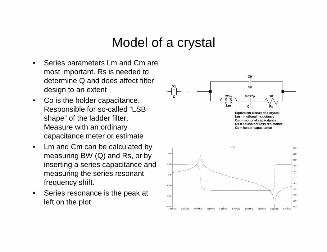
Model of a crystal• Series parameters Lm and Cm are
most important. Rs is needed todetermine Q and does affect filterdesign to an extent
• Co is the holder capacitance.Responsible for so-called “LSBshape” of the ladder filter.Measure with an ordinarycapacitance meter or estimate
• Lm and Cm can be calculated bymeasuring BW (Q) and Rs, or byinserting a series capacitance andmeasuring the series resonantfrequency shift.
• Series resonance is the peak atleft on the plot
X1
C 22m
Lm
0.017p
Cm
10
Rs
C0
4p
Equivalent circuit of a crystalLm = motional inductanceCm = motional capacitanceRs = equivalent loss resistanceCo = holder capacitance
=
7.992MHz 7.995MHz 7.998MHz 8.001MHz 8.004MHz 8.007MHz 8.010MHz 8.013MHz 8.016MHz 8.019MHz-105dB
-85dB
-65dB
-45dB
-25dB
-5dB
-200°
-160°
-120°
-80°
-40°
0°
40°
80°
120°
160°
200°V(out)
BW / Q method of parameter measurement• Two means of expressing Q of a tuned circuit are
Q = F/BW and Q = X/R• We know F (nameplate frequency of the crystal). If we measure BW
(3 dB bandwidth) and R, we can solve for X, which is the reactanceof Lm or Cm (they are equal). Then Lm and Cm follow easily.
• The crystal needs to “see” a well defined resistance on each end,typically 50 ohms or 12.5 ohms. The total circuit R will be twice thisvalue plus Rs.
• The bandwidth (BW) will be small, maybe 200 Hz or so, we need anaccurate frequency reading and a stable generator
• We don’t need a fancy meter to show -3dB points. Just a relativereading of voltage and a simple 3 dB pad that can be switched inand out.
• The Q we measure is loaded Q. Crystal Q is X/Rs
Signal Generator
• For BW / Q method, 1 Hz readout and stability needed• Some examples in my shack include:
– NJQRP DDS synthesizer– Multi-Pig PLL/VCO oscillator plus counter– K8IQY PVXO precision VXO plus counter
• Generator should have a defined (typ 50 ohm) source R• This can be achieved by adding 50 ohm in/out pads to
the output• The generator should put out a good, low distortion sine
wave. Uses low pass filtering as needed.
Detector for BW / Q method• After the crystal test fixture (and possibly some
amplification) comes the detector, which is just a(typically) 50 ohm load and an RF voltmeter
• The voltmeter can be a simple 1N34A diode detectorand DMM as in the K8IQY and W1FB circuits, or anamplified (“NORTEX Accu-Probe”) and compensated RFprobe if your circuit has high attenuation or low driveamplitude
• Some homebrewers may prefer to use their oscilloscopeto view the amplitude of the signal at the 50 ohm load
• If the -3 dB switchable pad is used, only a relativereading is needed. Otherwise, reading a peak value andthen 0.707 times that value is required.
• I use a Kanga log power meter as my detector
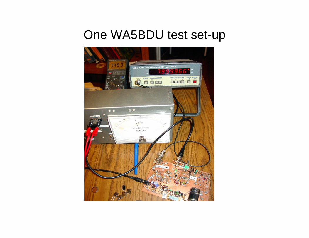
One WA5BDU test set-up
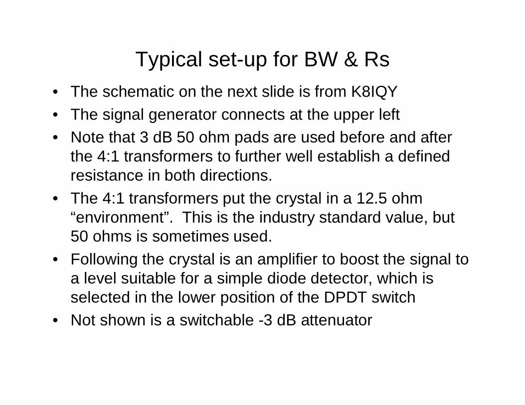
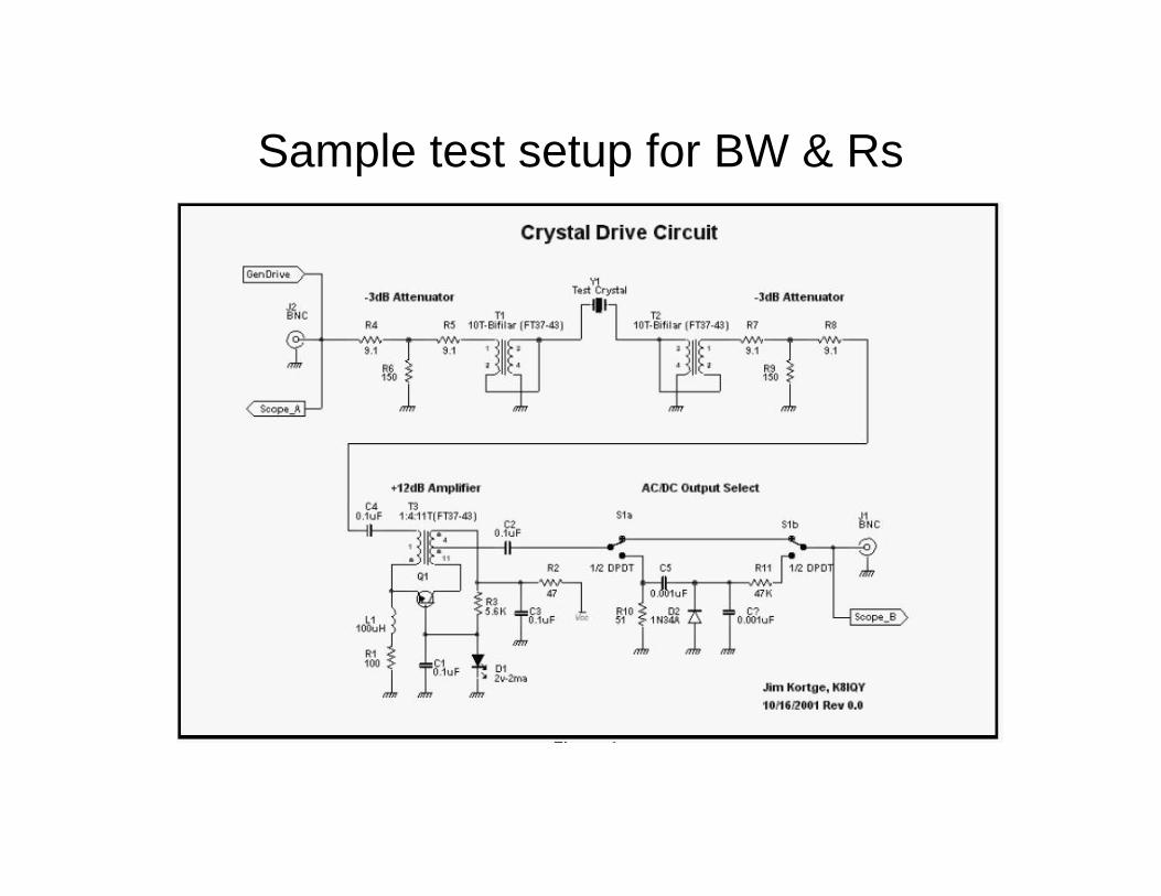
Typical set-up for BW & Rs• The schematic on the next slide is from K8IQY• The signal generator connects at the upper left• Note that 3 dB 50 ohm pads are used before and after
the 4:1 transformers to further well establish a definedresistance in both directions.
• The 4:1 transformers put the crystal in a 12.5 ohm“environment”. This is the industry standard value, but50 ohms is sometimes used.
• Following the crystal is an amplifier to boost the signal toa level suitable for a simple diode detector, which isselected in the lower position of the DPDT switch
• Not shown is a switchable -3 dB attenuator
Sample test setup for BW & Rs
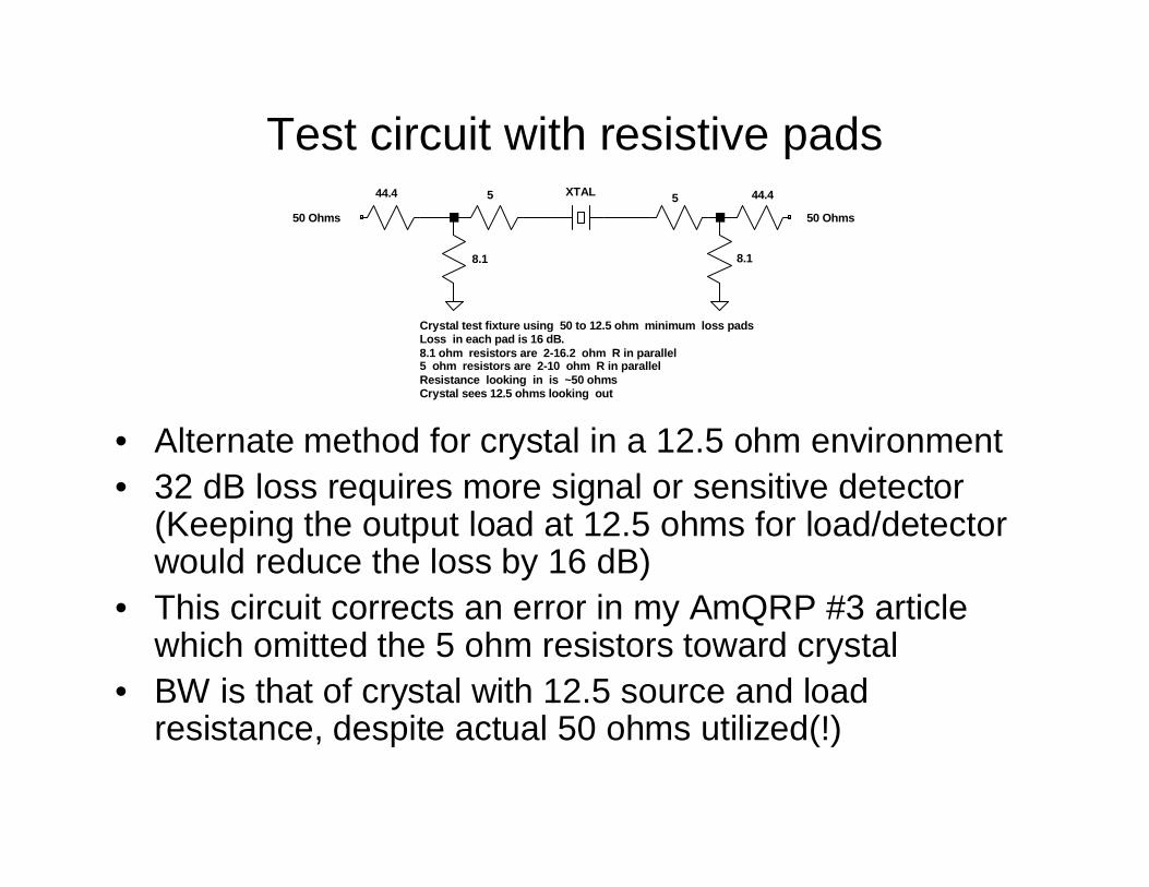
Test circuit with resistive pads
• Alternate method for crystal in a 12.5 ohm environment• 32 dB loss requires more signal or sensitive detector
(Keeping the output load at 12.5 ohms for load/detectorwould reduce the loss by 16 dB)
• This circuit corrects an error in my AmQRP #3 articlewhich omitted the 5 ohm resistors toward crystal
• BW is that of crystal with 12.5 source and loadresistance, despite actual 50 ohms utilized(!)
XTAL 55
8.1 8.1
44.4 44.4
50 Ohms 50 Ohms
Crystal test fixture using 50 to 12.5 ohm minimum loss padsLoss in each pad is 16 dB.8.1 ohm resistors are 2-16.2 ohm R in parallel5 ohm resistors are 2-10 ohm R in parallelResistance looking in is ~50 ohmsCrystal sees 12.5 ohms looking out
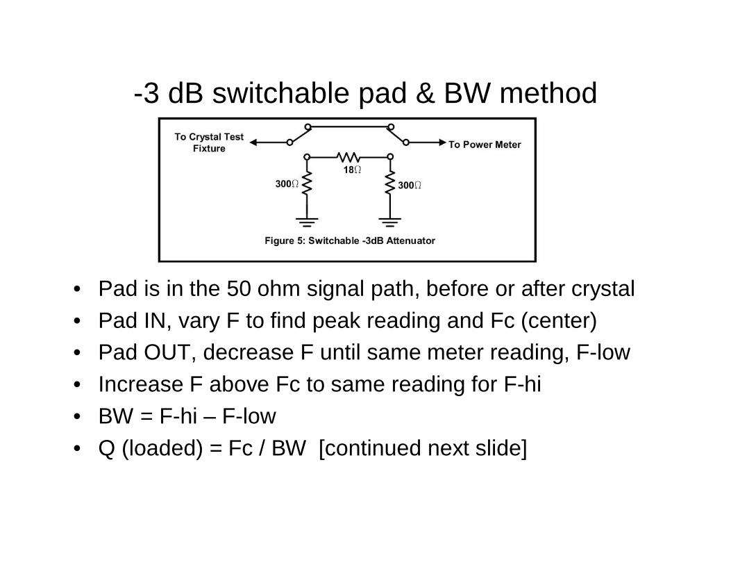
-3 dB switchable pad & BW method
• Pad is in the 50 ohm signal path, before or after crystal• Pad IN, vary F to find peak reading and Fc (center)• Pad OUT, decrease F until same meter reading, F-low• Increase F above Fc to same reading for F-hi• BW = F-hi – F-low• Q (loaded) = Fc / BW [continued next slide]
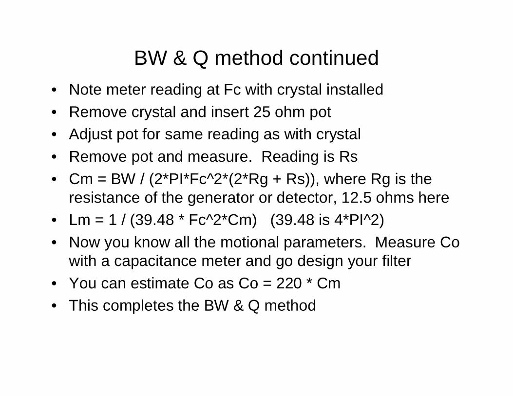
BW & Q method continued• Note meter reading at Fc with crystal installed• Remove crystal and insert 25 ohm pot• Adjust pot for same reading as with crystal• Remove pot and measure. Reading is Rs• Cm = BW / (2*PI*Fc^2*(2*Rg + Rs)), where Rg is the
resistance of the generator or detector, 12.5 ohms here• Lm = 1 / (39.48 * Fc^2*Cm) (39.48 is 4*PI^2)• Now you know all the motional parameters. Measure Co
with a capacitance meter and go design your filter• You can estimate Co as Co = 220 * Cm• This completes the BW & Q method
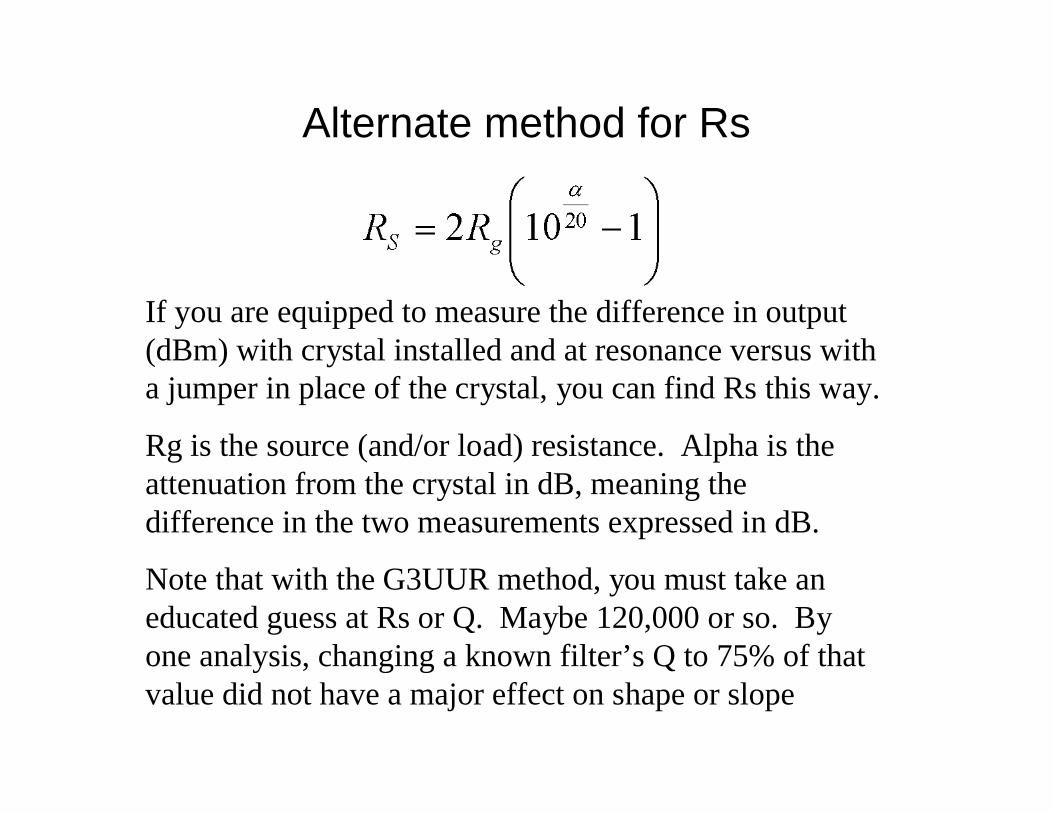
Alternate method for Rs
If you are equipped to measure the difference in output(dBm) with crystal installed and at resonance versus witha jumper in place of the crystal, you can find Rs this way.
Rg is the source (and/or load) resistance. Alpha is theattenuation from the crystal in dB, meaning thedifference in the two measurements expressed in dB.
Note that with the G3UUR method, you must take aneducated guess at Rs or Q. Maybe 120,000 or so. Byone analysis, changing a known filter’s Q to 75% of thatvalue did not have a major effect on shape or slope
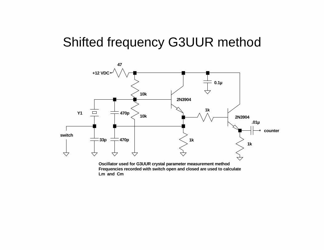
Shifted frequency G3UUR method
Y1
33p
470p
470p
10k
2N3904
2N3904
1k
10k
1k
1k
0.1µ
.01µ
47
switch
+12 VDC
counter
Oscillator used for G3UUR crystal parameter measurement methodFrequencies recorded with switch open and closed are used to calculateLm and Cm
G3UUR measurement method• Measure the frequency with the switch open (f1)• Measure the frequency with the switch closed (f2)• Plug into the formulas for Lm and Cm and you’re done• This method does not measure Rs• Measure Co with a capacitance meter or estimate as in
the BW / Q method• Chris Trask N7ZWY circuit for frequency shift• Improved oscillator assures series resonance operation• Also incorporates measurements to give Rs• Relatively new with few user comments as yethttp://www.home.earthlink.net/~christrask/Crystal%20Test%20Set.pdf
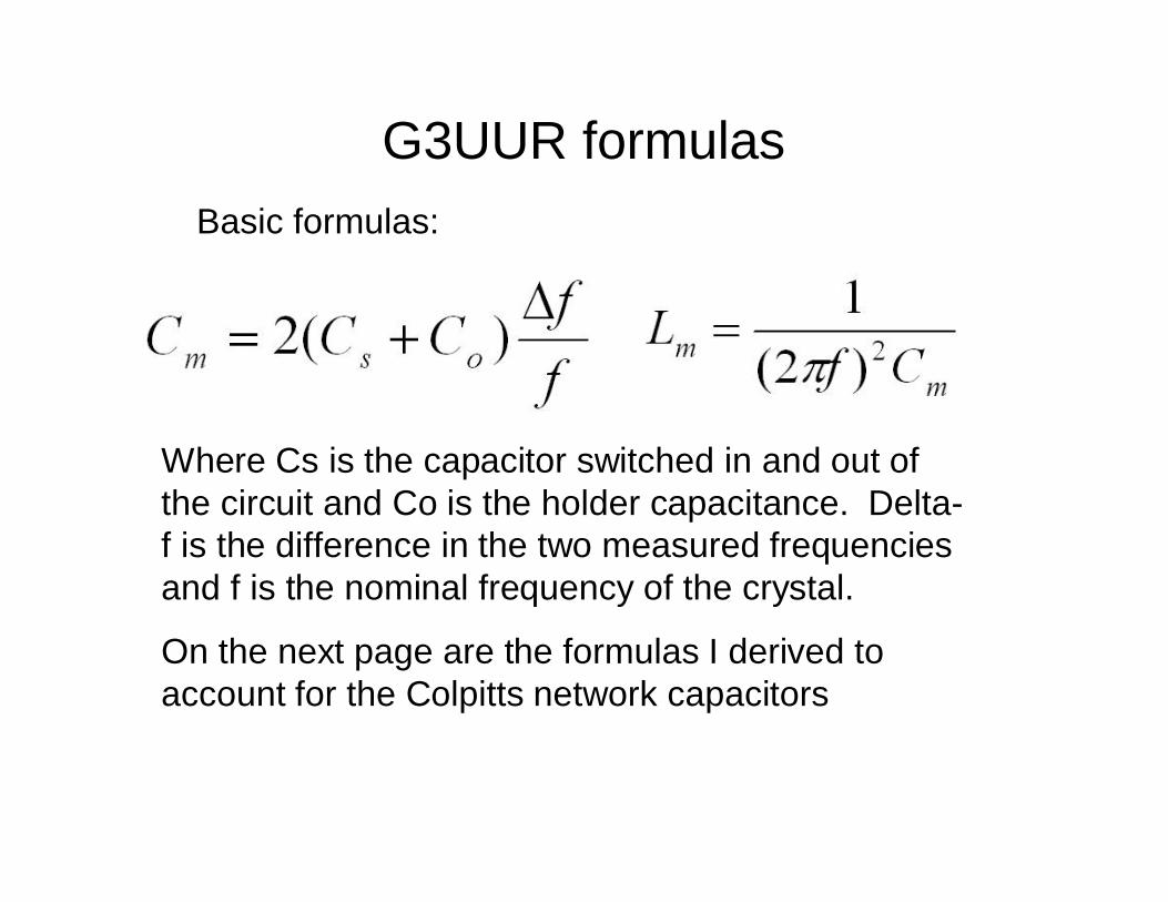
G3UUR formulasBasic formulas:
Where Cs is the capacitor switched in and out ofthe circuit and Co is the holder capacitance. Delta-f is the difference in the two measured frequenciesand f is the nominal frequency of the crystal.
On the next page are the formulas I derived toaccount for the Colpitts network capacitors
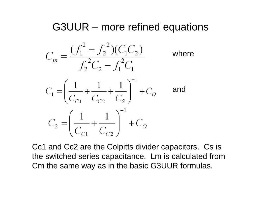
G3UUR – more refined equations
where
and
Cc1 and Cc2 are the Colpitts divider capacitors. Cs isthe switched series capacitance. Lm is calculated fromCm the same way as in the basic G3UUR formulas.
How accurate are the readings?• Darell Brehm WA3OPY measured my crystals on ICM’s
professional equipment and passed them to Bill CarverK7AAZ to measure on a N2PK VNA
• I compared them to my own measurements using theBW/Q method, G3UUR method with original andenhanced calculations, and Chris Trask method
• Measurements generally agree to within 5% or better• When I changed the Lm/Cm values on an XLAD filter
design by 5%, the resulting shape still looked very goodalthough the BW changed a bit.
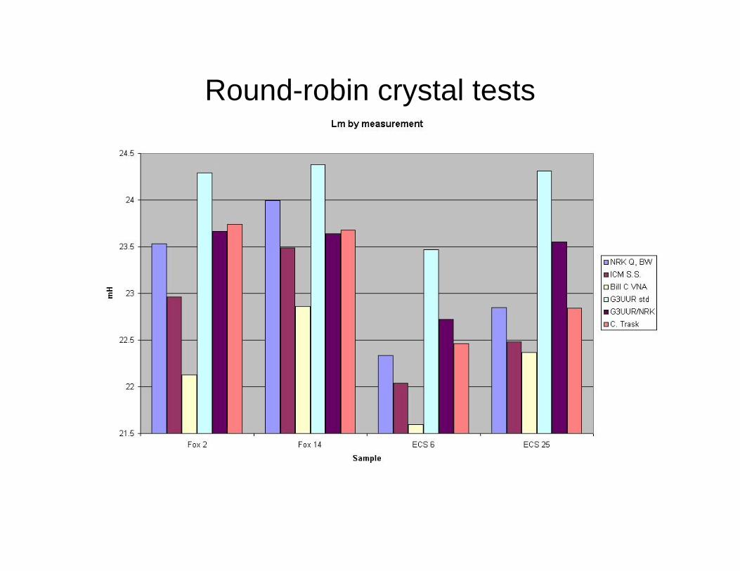
Round-robin crystal tests
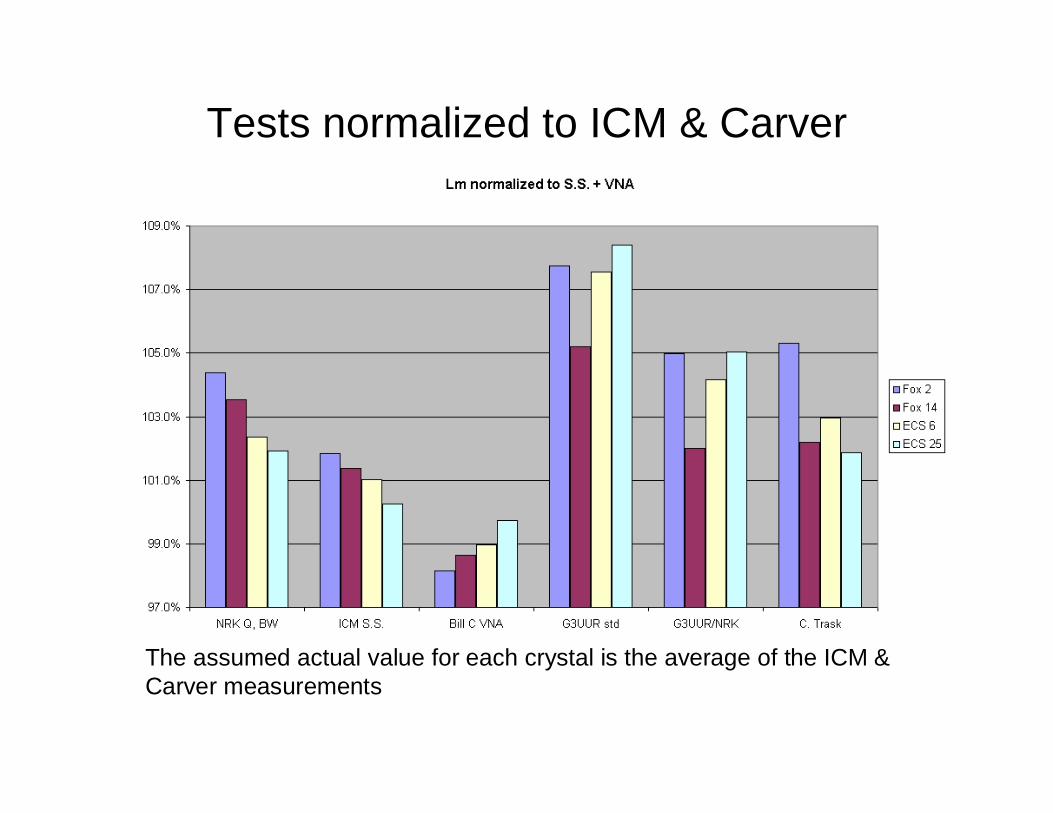
Tests normalized to ICM & Carver
The assumed actual value for each crystal is the average of the ICM &Carver measurements
Designing your filters• Crystal filter design is a rather complex process if done
from the base mathematics or using coefficients from abook. Moreover, books with tables adjusted for non-optimum Q (“predistorted”) are specialized andsomewhat expensive at $70 and up used.
• Software to the rescue …• Wes Hayward’s XLAD and GPLA programs were
originally sold commercially, then included in DOSversions with IRFD, then Windows versions in EMRFD.
• AADE’s Filter Design program was originally commercialbut became freeware recently.
• Both perform design and provide analysis (responsecurves).
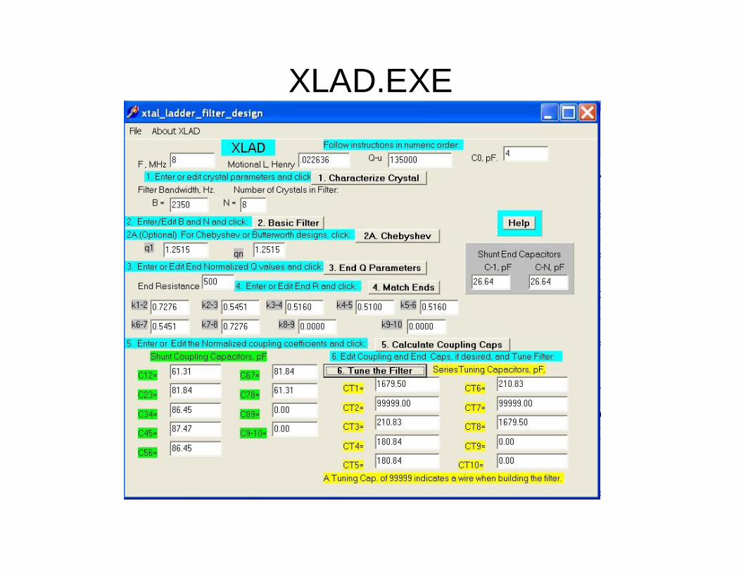
XLAD & GPLA• XLAD designs the filter. It asks for frequency, Lm, Q and
Co of the crystals and desired filter bandwidth.• Minimum end resistances aren’t given directly, but can
be found by reducing until an error occurs. Highervalues are matched with end capacitors.
• Designs a Gaussian to 6 dB, Butterworth, or Chebyshev• Provides tuning capacitors for the meshes• File saved by XLAD can be analyzed (response curves)
by GPLA. The LadBuild program will show the circuitschematically if the subscripted data is confusing
• XLAD attempts to compensate for Q and Co. If BW asseen on GPLA is off, adjust and run XLAD again.
XLAD.EXE
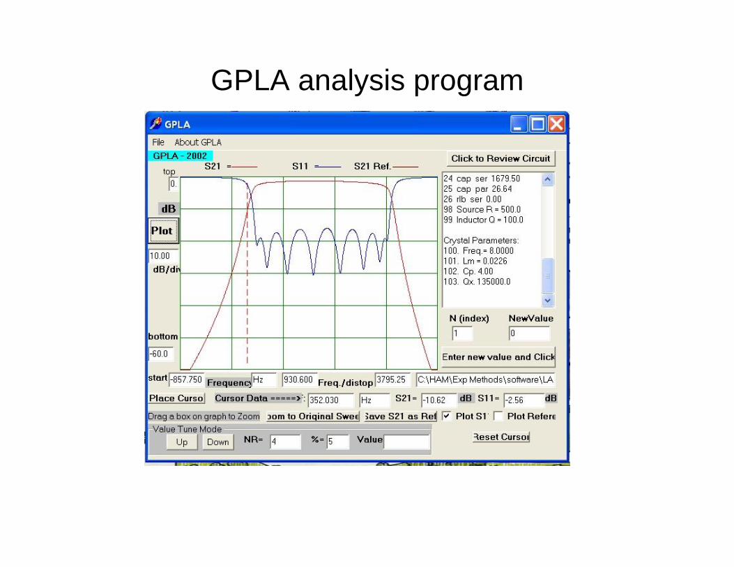
GPLA analysis program
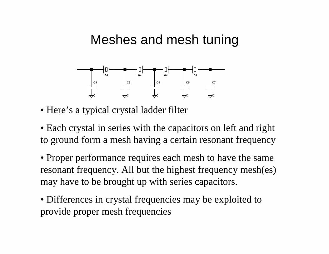
Meshes and mesh tuning
X2 X3 X4
C4
C
C5
C
C6
C
C7
C
X1
C9
C
• Here’s a typical crystal ladder filter
• Each crystal in series with the capacitors on left and rightto ground form a mesh having a certain resonant frequency
• Proper performance requires each mesh to have the sameresonant frequency. All but the highest frequency mesh(es)may have to be brought up with series capacitors.
• Differences in crystal frequencies may be exploited toprovide proper mesh frequencies
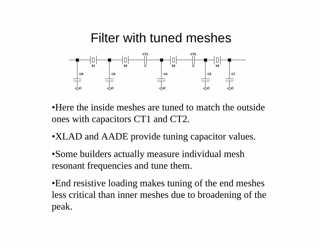
Filter with tuned meshes
X2 X3 X4
C4
C
C5
C
C6
C
C7
C
X1
C9
C
CT1
C
CT2
C
•Here the inside meshes are tuned to match the outsideones with capacitors CT1 and CT2.
•XLAD and AADE provide tuning capacitor values.
•Some builders actually measure individual meshresonant frequencies and tune them.
•End resistive loading makes tuning of the end meshesless critical than inner meshes due to broadening of thepeak.
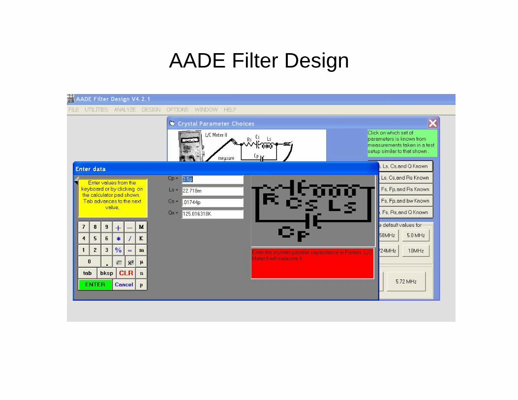
AADE Filter Design
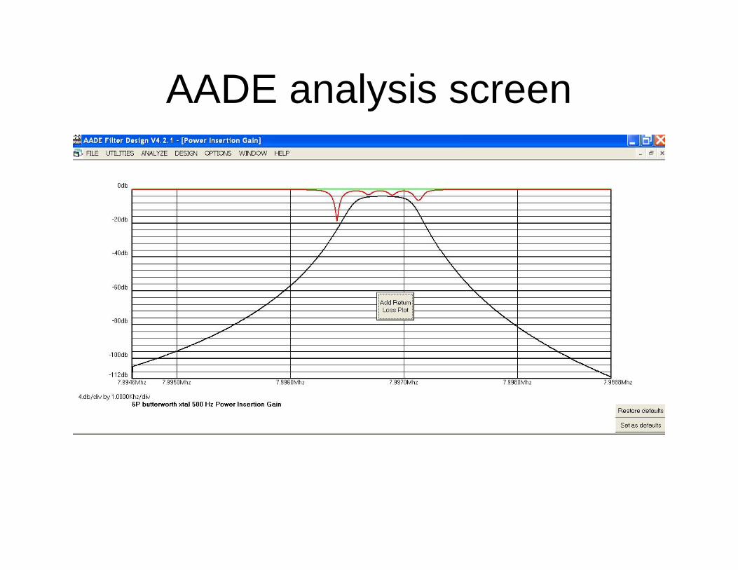
AADE analysis screen
AADE Filter Design• User input is similar to XLAD. User inputs Lm, Cm, Q or
Rs, Co and desired bandwidth. (AADE symbols vary forthese parameters)
• Filter Design offers about a dozen common and lesscommon crystal filter types, Butterworth, Chebyshev,Gaussian, Bessel, Linear Phase, Cohn, etc.
• AADE designs a matching L/C end section to matchhigher or lower loads compared with XLAD’s shuntcapacitors to match higher R values
• Results with AADE or XLAD designer will typically behigh or low on bandwidth on the first attempt, as viewedon the analyzer software. Adjust and repeat as required.
Other analysis software: SPICE
• There’s little need for additional software since bothXLAD and Filter Design include software to display theresponse curves.
• But other software, such as LTSpice allow options suchas using specific parameters for each crystal instead ofaverage values for the set. Also, the user may want toview filter performance with pre- and post- filteramplifiers, for example.
• Regardless of the analysis tool, response curves allowcalculating a figure of merit known as shape factor,which is the ratio of bandwidth at -6 dB and -60 dBpoints
Matching - both directions• The filter requires termination in the design resistance
value on both ends to perform properly• The view looking into the filter from the driver or load
stage normally presents the same resistance value• The return loss plot will tell how well the filter does this.
Higher return loss means a better match.• If necessary, a resistive pad or intermediate amplifier
with well defined input and output R might be needed, forexample between the mixer and the crystal filter
• Generally, your filter’s design resistance is constrainedby various factors to a certain range. You’ll match it torequired values in your design with transformers,networks, etc.
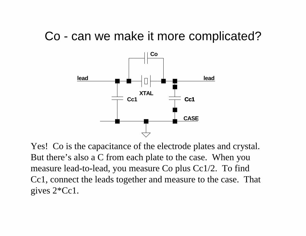
Co - can we make it more complicated?
Yes! Co is the capacitance of the electrode plates and crystal.But there’s also a C from each plate to the case. When youmeasure lead-to-lead, you measure Co plus Cc1/2. To findCc1, connect the leads together and measure to the case. Thatgives 2*Cc1.
XTALCc1
Co
Cc1Cc1Cc1
CASE
leadlead
Co adjustments continued• If you ground your crystal cases, reduce the measuredCo by 1/2 of the Cc1 measurement
• If in your filter you have a coupling capacitor Cjkbetween crystals j and k to ground, you should reduceits design value by Cc1 * 2 when you ground yourcrystal cases
• These corrections are generally used by more exactingbuilders and may usually be omitted without seriousproblems. Designs with small capacitor values maybenefit more from the adjustments.
What kind(s) of crystals & capacitors?
• Dipped silver mica capacitors are often used but otherquality RF capacitors may be used
• Keep an assortment of values. Combining in parallel orseries will usually allow hitting calculated values within apF or two. Measuring each capacitor rather than trustingthe marking is a good idea.
• HC49/U crystals are often used by amateurs in filters.Perhaps contrary to intuition, the shorter HC49/UScrystals can also have good Q.
• As a case in point, consider the space limited ATS-3 withshort crystals and SMT ceramics but good performance.
That LSB shape• Crystal ladder filters typically have a response curve
that is less steep on the lower side due to the effect ofCo. Less pronounced with larger number of poles.
• This is generally not a problem but may be with verywide filters
• On method of compensation described by Hayward isto add resonating inductors in parallel with eachcrystal. This technique produces a symmetrical shapearound the passband, but be aware that well removedfrom the filter frequency, ultimate rejection is reducedsomewhat
• The Dishal filter design can produce a USB shape.The AADE program describes and implements it
What type of filter?• Since they generally look alike physically and
schematically, difficulty of building is not a consideration• We trade steep sides and flatness of passband against
time domain behavior and “sound”• Our response curves show attenuation of sine waves
over a range of frequencies. They do not show phaseshifts and delays at each discrete frequency. These mayaffect naturalness of sound, “ringing” behavior, anddistortion of timed pulses used in data modes
• Mathematical descriptions of the derivation of variousfilter shapes are interesting but complex. Thehomebrewer will generally research qualitativedescriptions and choose the type for his application
Filter types - continued• Chebyshev 0.1 dB is perhaps the most common choice
for SSB & CW filters• Chebyshev and Butterworth filters will both have some
ringing and delay affecting digital modes. Types moreoptimal for digital modes include Gaussian, Gaussian to6 and 12 dB, and linear phase types
• The Cohn or “min-loss” filter is a favorite amongexperimenters because the capacitors are all of equalvalue. As such, mesh tuning capacitors are not needed.Note that the end capacitors in the Cohn filter are series(not shunt).
Assessing filter performance• Generally, actual performance is reasonably close to
predicted so measurements aren’t absolutely necessary• Your qualitative assessment -- install the filter in your
receiver and listen -- can be the most valuable test• I record response at discrete points using my log power
meter and signal generator, then plot the result in Excel• Obviously, a spectrum analyzer will give the best and
easiest to produce picture of filter performance• One effective but inexpensive method is to use PC
soundcard software such as Spectrogram. Use a noisegenerator into your receiver and pipe the audio to thePC. It won’t go to -100 dB, but shows the overall shapewell
Facts, opinions & quotes• Co (holder capacitance) is usually approximated by Co =
220Cm, which is derived from the physics of an AT cut crystal.Add ½ to 1 pf to this (rule of thumb) (1) (2)
• Always ground the crystal case. (3) (Note that some authorsstate that they do not ground the case for fear of damagecaused by soldering.)
• If the crystal case is grounded, reduce the measured Co by halfthe capacitance measured from both pins shorted together tothe case. (3)
• Chebyshev filters tear up the timed pulses of RTTY, AMTOR,or Clover signals. Two good choices for data modes areGaussian-6-dB and Gaussian-to-12 dB designs.
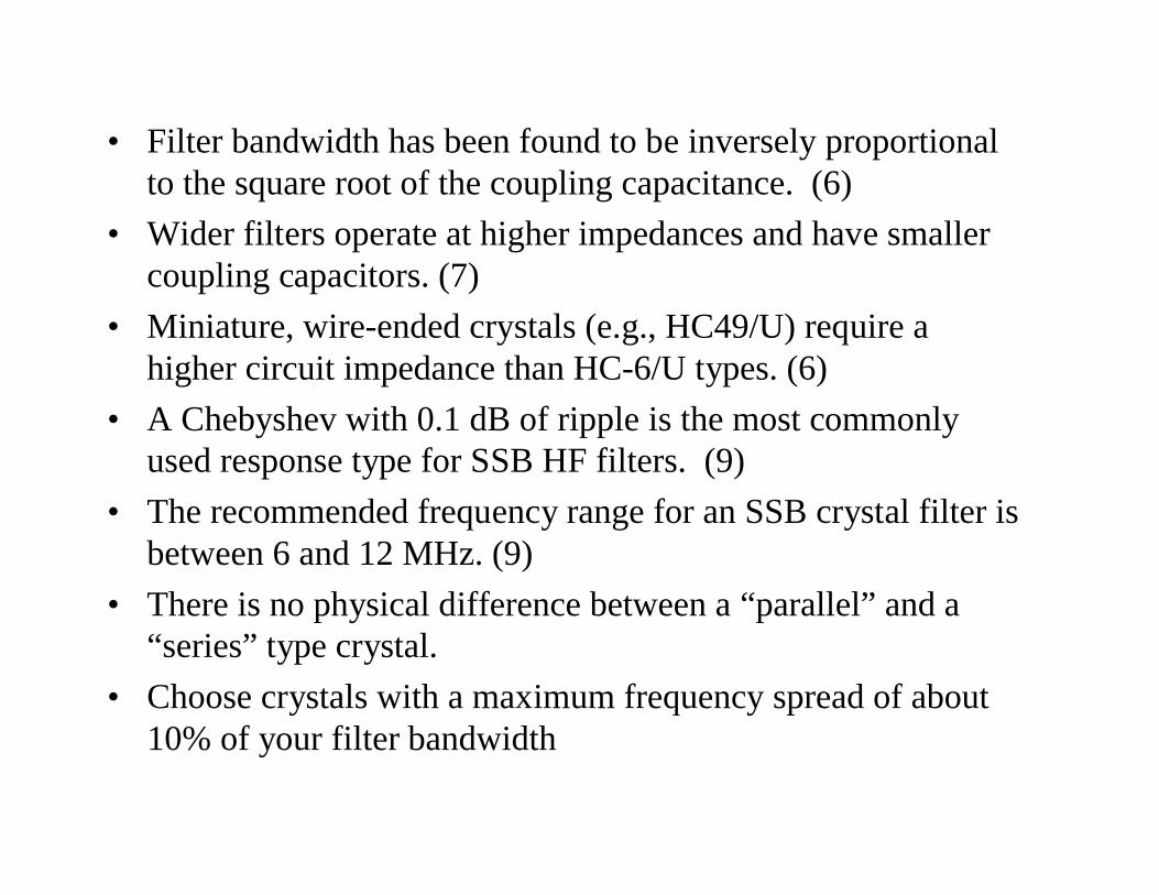
• Filter bandwidth has been found to be inversely proportionalto the square root of the coupling capacitance. (6)
• Wider filters operate at higher impedances and have smallercoupling capacitors. (7)
• Miniature, wire-ended crystals (e.g., HC49/U) require ahigher circuit impedance than HC-6/U types. (6)
• A Chebyshev with 0.1 dB of ripple is the most commonlyused response type for SSB HF filters. (9)
• The recommended frequency range for an SSB crystal filter isbetween 6 and 12 MHz. (9)
• There is no physical difference between a “parallel” and a“series” type crystal.
• Choose crystals with a maximum frequency spread of about10% of your filter bandwidth
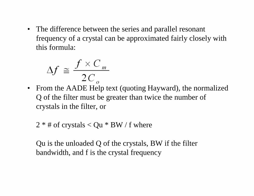
• The difference between the series and parallel resonantfrequency of a crystal can be approximated fairly closely withthis formula:
• From the AADE Help text (quoting Hayward), the normalizedQ of the filter must be greater than twice the number ofcrystals in the filter, or
2 * # of crystals < Qu * BW / f where
Qu is the unloaded Q of the crystals, BW if the filterbandwidth, and f is the crystal frequency
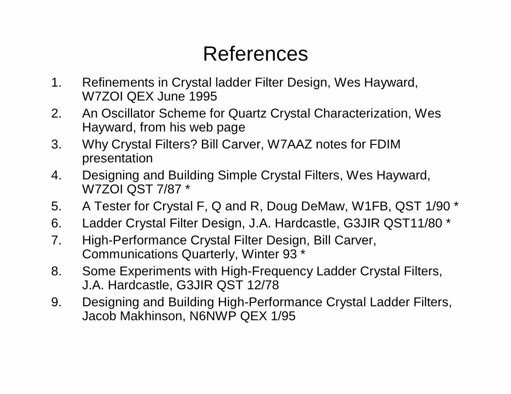
References1. Refinements in Crystal ladder Filter Design, Wes Hayward,
W7ZOI QEX June 19952. An Oscillator Scheme for Quartz Crystal Characterization, Wes
Hayward, from his web page3. Why Crystal Filters? Bill Carver, W7AAZ notes for FDIM
presentation4. Designing and Building Simple Crystal Filters, Wes Hayward,
W7ZOI QST 7/87 *5. A Tester for Crystal F, Q and R, Doug DeMaw, W1FB, QST 1/90 *6. Ladder Crystal Filter Design, J.A. Hardcastle, G3JIR QST11/80 *7. High-Performance Crystal Filter Design, Bill Carver,
Communications Quarterly, Winter 93 *8. Some Experiments with High-Frequency Ladder Crystal Filters,
J.A. Hardcastle, G3JIR QST 12/789. Designing and Building High-Performance Crystal Ladder Filters,
Jacob Makhinson, N6NWP QEX 1/95
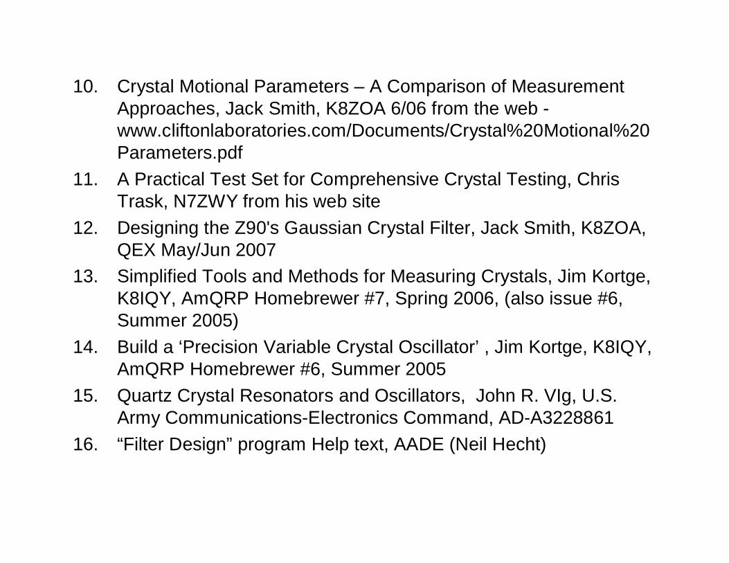
10. Crystal Motional Parameters – A Comparison of MeasurementApproaches, Jack Smith, K8ZOA 6/06 from the web -www.cliftonlaboratories.com/Documents/Crystal%20Motional%20Parameters.pdf
11. A Practical Test Set for Comprehensive Crystal Testing, ChrisTrask, N7ZWY from his web site
12. Designing the Z90's Gaussian Crystal Filter, Jack Smith, K8ZOA,QEX May/Jun 2007
13. Simplified Tools and Methods for Measuring Crystals, Jim Kortge,K8IQY, AmQRP Homebrewer #7, Spring 2006, (also issue #6,Summer 2005)
14. Build a ‘Precision Variable Crystal Oscillator’ , Jim Kortge, K8IQY,AmQRP Homebrewer #6, Summer 2005
15. Quartz Crystal Resonators and Oscillators, John R. VIg, U.S.Army Communications-Electronics Command, AD-A3228861
16. “Filter Design” program Help text, AADE (Neil Hecht)
Sources for documents
• The CD from EMRFD contains several classic articles oncrystal measurements and filter design
• The AADE “Filter Design” program’s Help section alsoincludes several classic papers
• ARRL’s “QRP Power” book includes two papers oncrystal measurement and filter design
• The ARRL web site includes a number of relevantpapers from QEX and QST for its members