Embed Size (px)
Citation preview
4/8/2008
1
MICROPILES SUBJECT TO
LATERAL LOADING
Dr. Jesús Gómez, P.E.Micropile Design and Construction Seminar
Las Vegas, NVgApril 3-4, 2008
Outline
When are micropiles subject to lateral p jload?How do we analyze them?Load testingCase histories
4/8/2008
2
Where are micropiles subject to lateral load?
Building foundations (earthquake, g ( q ,wind)Basement wall foundationsRetaining wall foundationsExcavation supportT d t k f d tiTower and stack foundationsMachine foundationsSlope stabilization
Why not use another foundation system?
Other solutions such as caissons or piles are not necessarily betterp yMicropiles are installed within tight areasMicropiles can be inclinedAdvancing through difficult formations and obstructions
4/8/2008
3
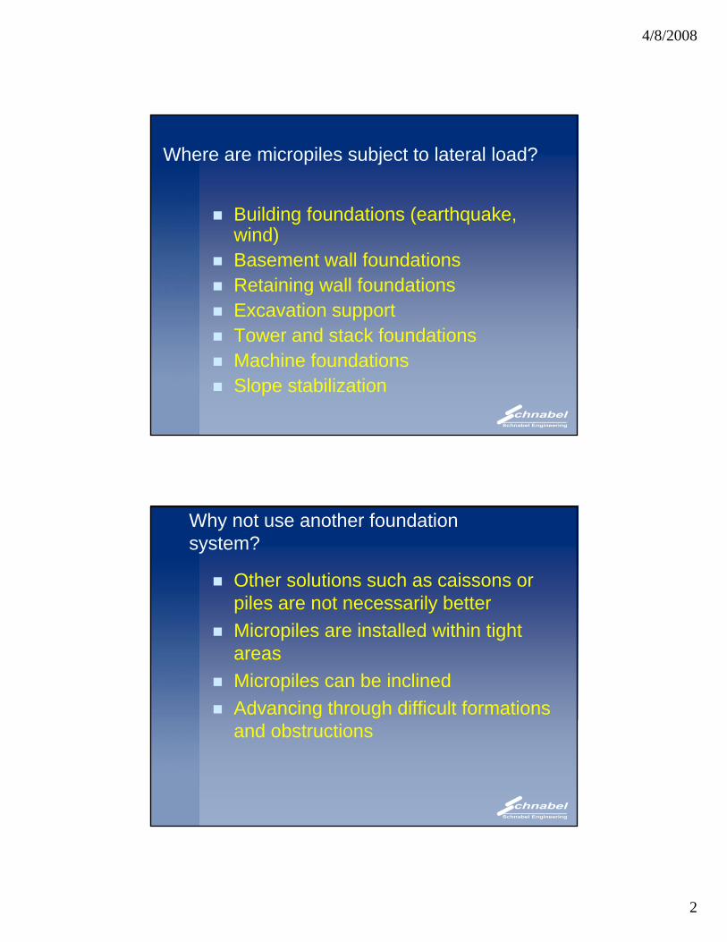
Building foundations
PVV
Issues for analysis
Analysis almost identical to other yfoundationsMicropile characteristicsFixity of micropile headSoil propertiesPil i tPile cap resistanceTolerable displacementBending capacity of micropileAre batter piles necessary?
4/8/2008
4
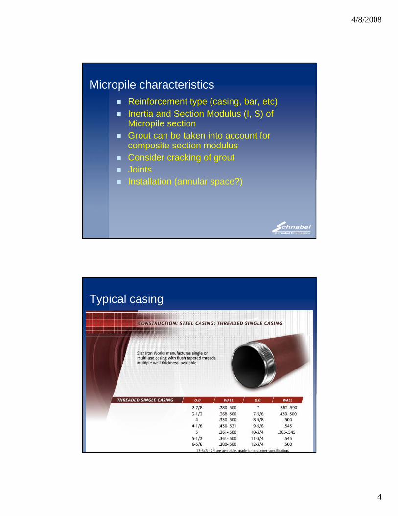
Micropile characteristicsReinforcement type (casing, bar, etc)Inertia and Section Modulus (I, S) of Mi il tiMicropile sectionGrout can be taken into account for composite section modulusConsider cracking of groutJointsInstallation (annular space?)Installation (annular space?)
Typical casing
4/8/2008
5
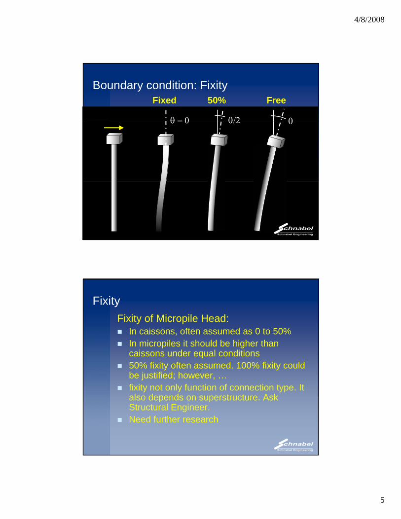
θθ = 0
Fixed
θ/2
50% FreeBoundary condition: Fixity
θθ 0 θ/2
FixityFixity of Micropile Head:
In caissons, often assumed as 0 to 50%In micropiles it should be higher than caissons under equal conditions50% fixity often assumed. 100% fixity could be justified; however, …fixity not only function of connection type. It also depends on superstructure Askalso depends on superstructure. Ask Structural Engineer.Need further research
4/8/2008
6
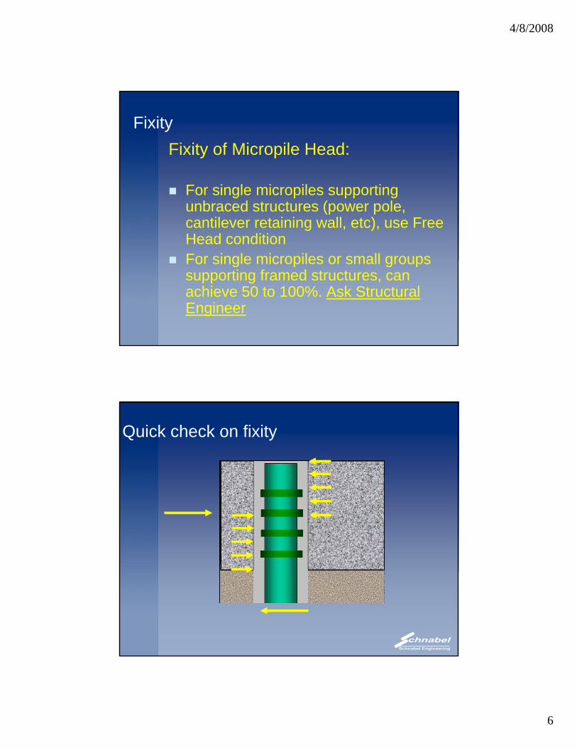
FixityFixity of Micropile Head:
For single micropiles supporting unbraced structures (power pole, cantilever retaining wall, etc), use Free Head conditionFor single micropiles or small groupsFor single micropiles or small groups supporting framed structures, can achieve 50 to 100%. Ask Structural Engineer
Quick check on fixity
4/8/2008
7
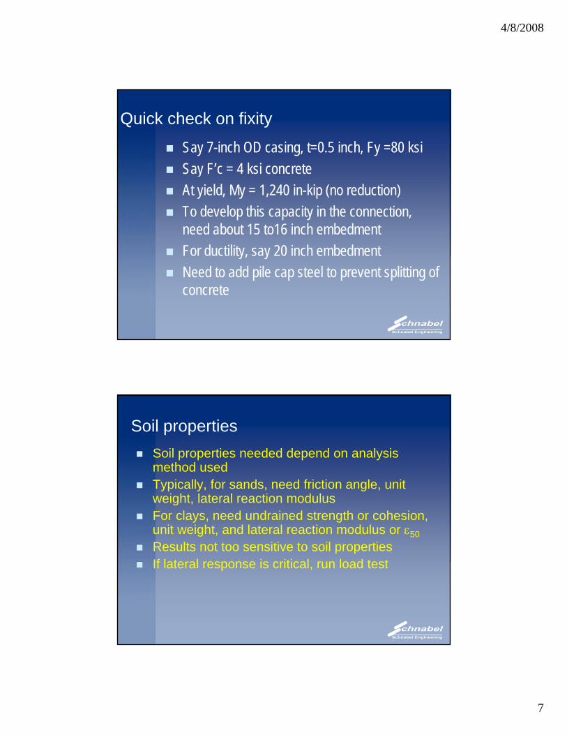
Quick check on fixity
Say 7-inch OD casing, t=0.5 inch, Fy =80 ksiSay F’c = 4 ksi concreteSay F c 4 ksi concreteAt yield, My = 1,240 in-kip (no reduction)To develop this capacity in the connection, need about 15 to16 inch embedmentFor ductility, say 20 inch embedmenty, yNeed to add pile cap steel to prevent splitting of concrete
Soil propertiesSoil properties needed depend on analysis method usedTypically, for sands, need friction angle, unit weight, lateral reaction modulusFor clays, need undrained strength or cohesion, unit weight, and lateral reaction modulus or ε50Results not too sensitive to soil propertiesIf lateral response is critical run load testIf lateral response is critical, run load test
4/8/2008
8
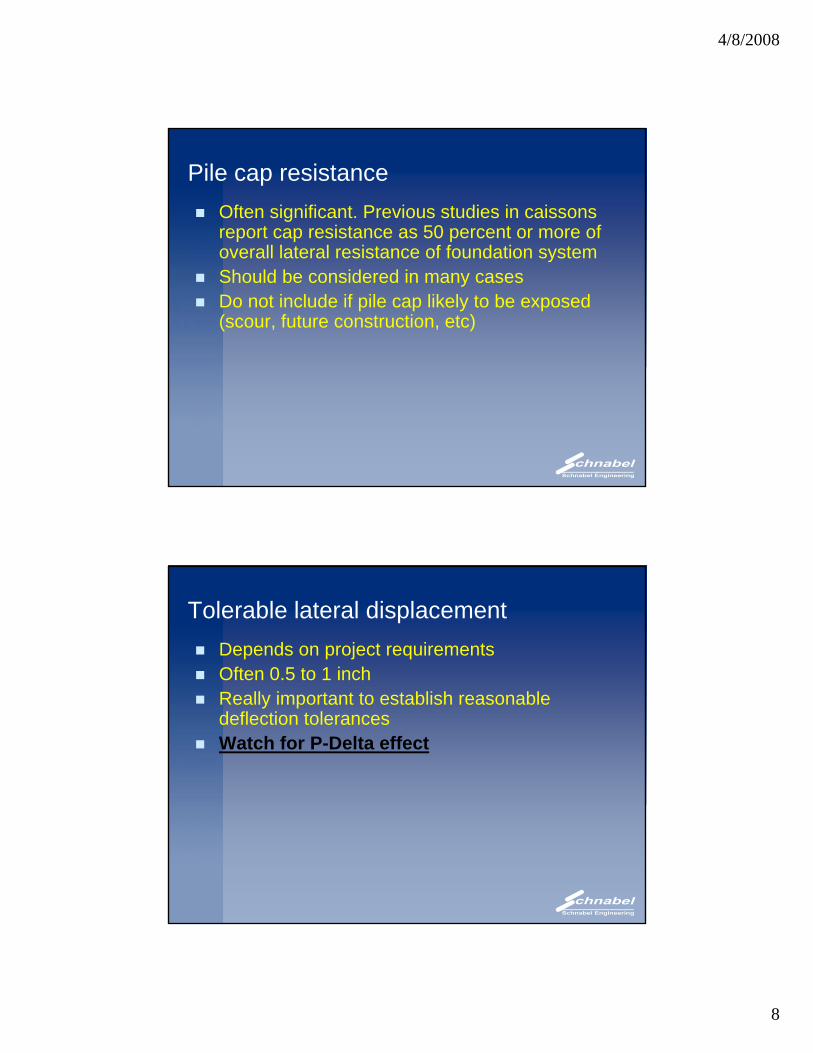
Pile cap resistanceOften significant. Previous studies in caissons report cap resistance as 50 percent or more of
ll l t l i t f f d ti toverall lateral resistance of foundation systemShould be considered in many casesDo not include if pile cap likely to be exposed (scour, future construction, etc)
Tolerable lateral displacementDepends on project requirementsOften 0.5 to 1 inchReally important to establish reasonable deflection tolerancesWatch for P-Delta effect
4/8/2008
9
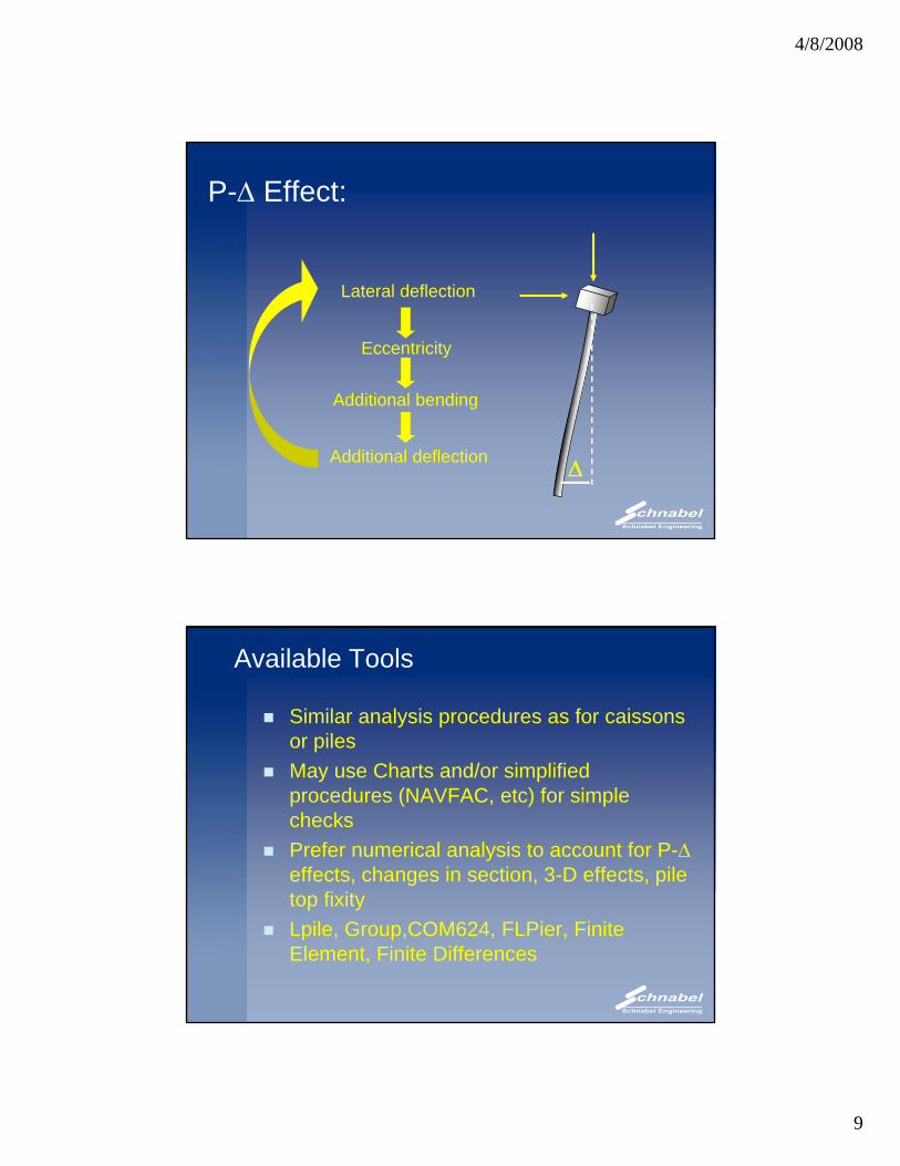
P-Δ Effect:
Lateral deflection
Eccentricity
Additional bending
ΔAdditional deflection
g
Available Tools
Similar analysis procedures as for caissons or pilesMay use Charts and/or simplified procedures (NAVFAC, etc) for simple checksPrefer numerical analysis to account for P-Δ effects, changes in section, 3-D effects, pile top fixityLpile, Group,COM624, FLPier, Finite Element, Finite Differences
4/8/2008
10
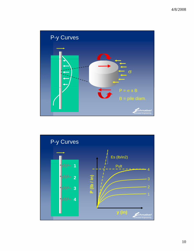
P-y Curves
σ
P = σ x B
B = pile diam.
P-y Curves
Es (lb/in2)
1
2
3
4
3
2
Pult
4
y (in)
1
4/8/2008
11
Example
0-0.5 0 0.5 1 1.5 2 2.5 3
Deflection (in)
50
100
150th (i
n)
1 kip
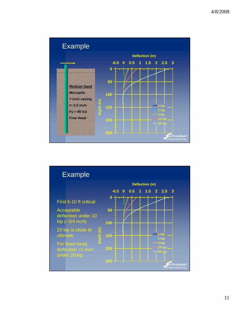
Medium Sand
Micropile:
7-inch casing
t= 0.5 inch 150
200
250
Dep
t
2 kip5 kip10 kip20 kip
Fy = 80 ksi
Free Head
Example
0-0.5 0 0.5 1 1.5 2 2.5 3
Deflection (in)
First 5 10 ft critical
50
100
150th (i
n)
1 kip
First 5-10 ft critical
Acceptable deflection under 10 kip (~3/4 inch)
20 kip is close to ultimate 150
200
250
Dep
t
2 kip5 kip10 kip20 kip
ultimate
For fixed head, deflection <1 inch under 20 kip
4/8/2008
12
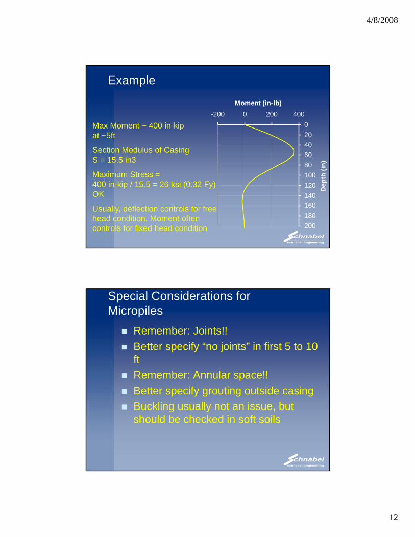
Example
Max Moment ~ 400 in-kip 0-200 0 200 400
Moment (in-lb)
Max Moment 400 in-kip at ~5ft
Section Modulus of Casing S = 15.5 in3
Maximum Stress = 400 in-kip / 15.5 = 26 ksi (0.32 Fy)
020406080100120 D
epth
(in)
p ( y)OK
Usually, deflection controls for free head condition. Moment often controls for fixed head condition
120140160180200
D
Special Considerations for Micropiles
Remember: Joints!!Better specify “no joints” in first 5 to 10Better specify no joints in first 5 to 10 ftRemember: Annular space!!Better specify grouting outside casingBuckling usually not an issue, but g y ,should be checked in soft soils
4/8/2008
13
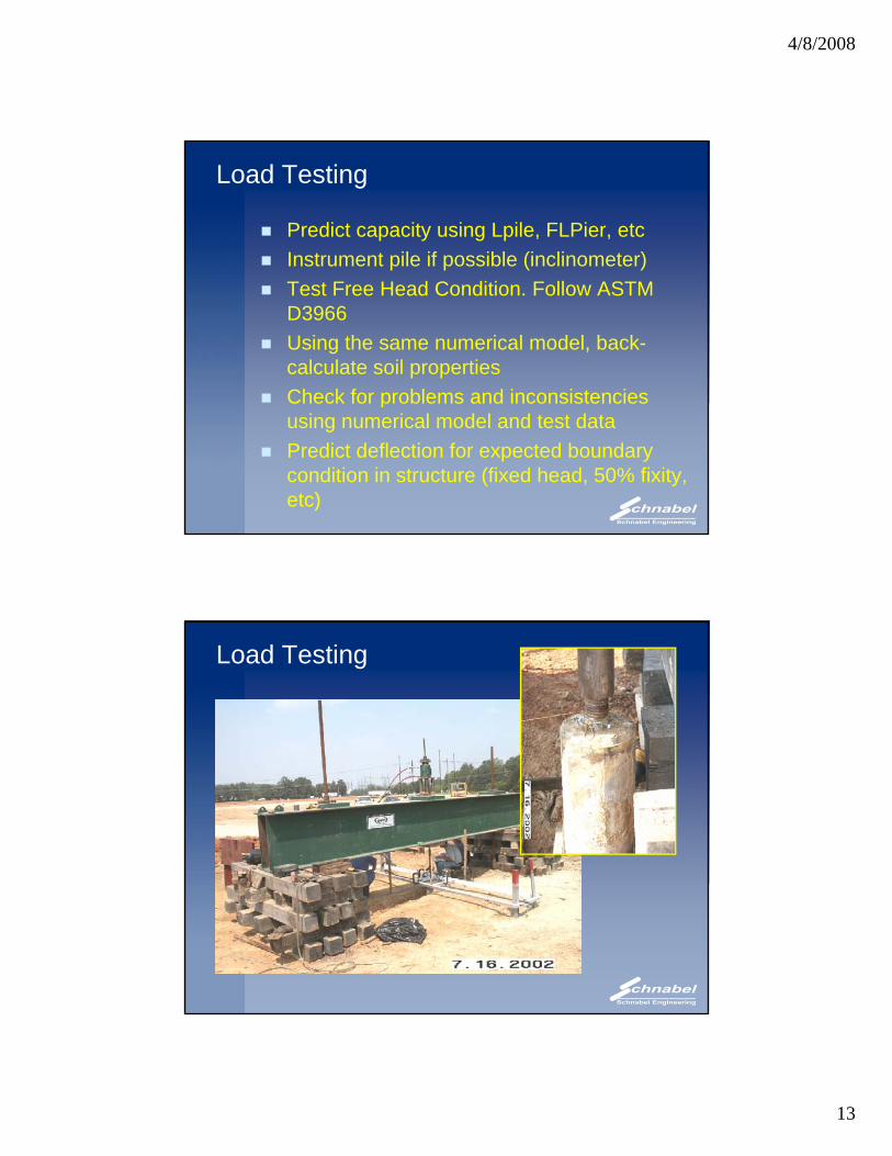
Load Testing
Predict capacity using Lpile, FLPier, etcInstrument pile if possible (inclinometer)Test Free Head Condition. Follow ASTM D3966 Using the same numerical model, back-calculate soil propertiesCheck for problems and inconsistenciesCheck for problems and inconsistencies using numerical model and test dataPredict deflection for expected boundary condition in structure (fixed head, 50% fixity, etc)
Load Testing
4/8/2008
14
Load Testing
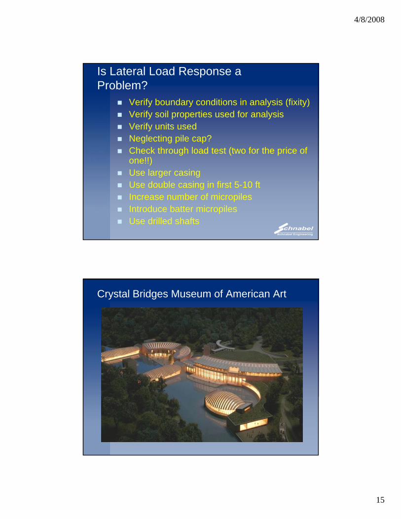
Load Testing
0
0.1
in)
0.2
0.3
0.4
0.5
0.60 5 10 15 20 25
Dis
plac
emen
t (i
Test Pile 1 Results
LPile calibration for Free-End condition
L-Pile calibration 50% Fixity
SCHNABEL ENGINEERING Length : 39 ft Date Installed : 7/11/2002 Date Tested : 7/16/2002 ASSOCIATES
Remarks: Lateral Load Test - TP-10.43" Thick Wall 80 ksi Steel4000 psi Grout2 - 15 ft. long #18 75 ksi Williamsform Bars
Design Load : 10 Kips
Test Load : 20 Kips CONTRACT NO. DATE
Pile Type : 7-5/8" O.D. Micropile Load Test Plot
Load (kips)
4/8/2008
15
Is Lateral Load Response a Problem?
Verify boundary conditions in analysis (fixity)Verify soil properties used for analysisVerify units usedNeglecting pile cap?Check through load test (two for the price of one!!)Use larger casingUse double casing in first 5-10 ftIncrease number of micropilesIntroduce batter micropilesUse drilled shafts
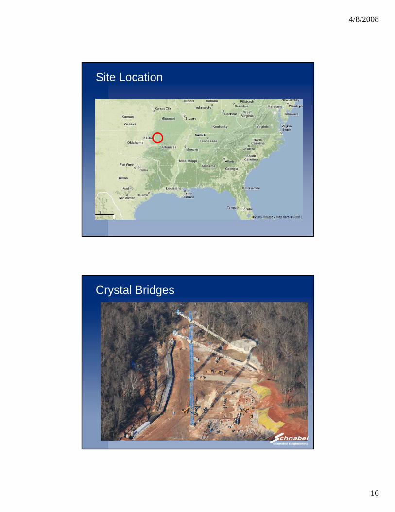
Crystal Bridges Museum of American Art
4/8/2008
16
Site Location
Crystal Bridges
4/8/2008
17
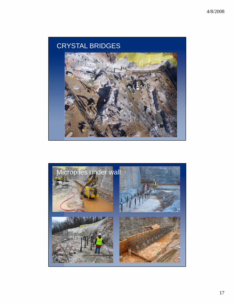
CRYSTAL BRIDGES
Micropiles under wall
4/8/2008
18
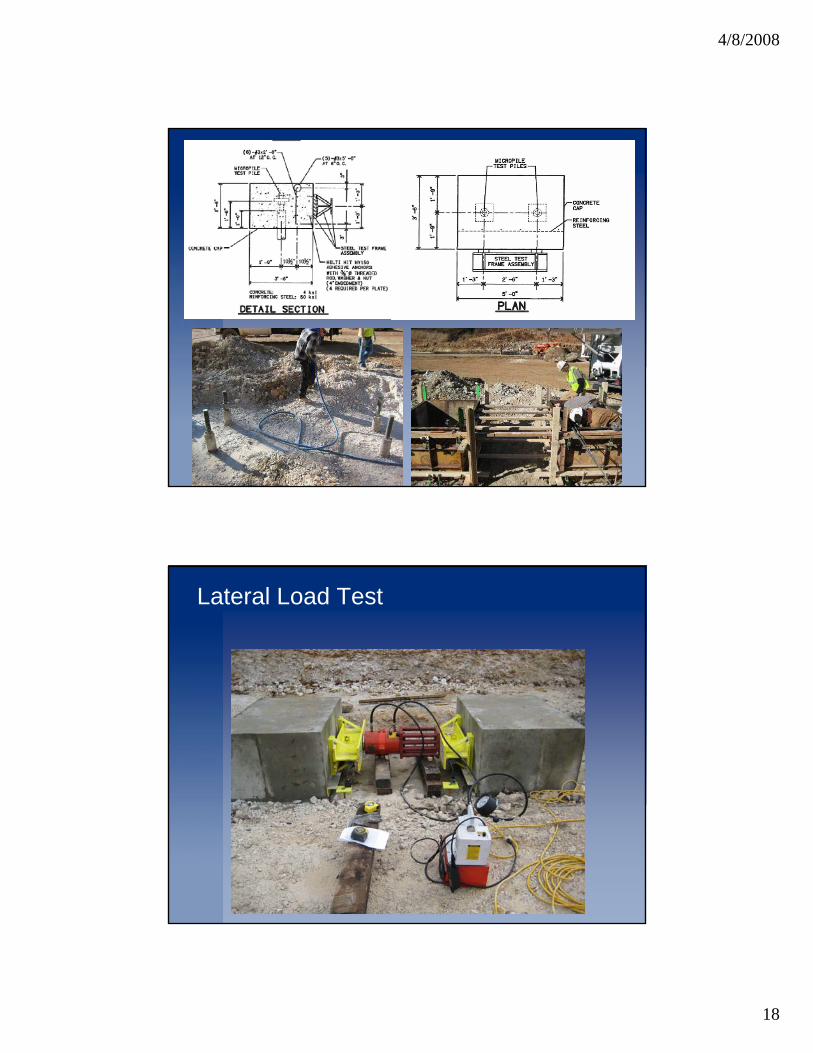
Lateral Load Test
4/8/2008
19
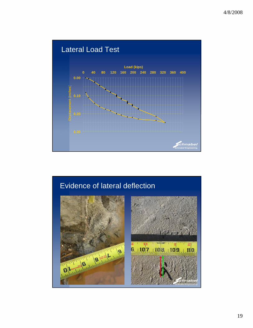
Lateral Load Test
0 000 40 80 120 160 200 240 280 320 360 400
Load (kips)
0.00
0.10
0 20plac
emen
t (in
ches
)
0.20
0.30
Dis
p
Evidence of lateral deflection
4/8/2008
20
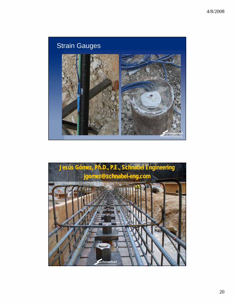
Strain Gauges
Jesús Gómez, Ph.D., P.E., Schnabel [email protected]
Jesús Gómez, Ph.D., P.E., Schnabel [email protected]
4/8/2008
21
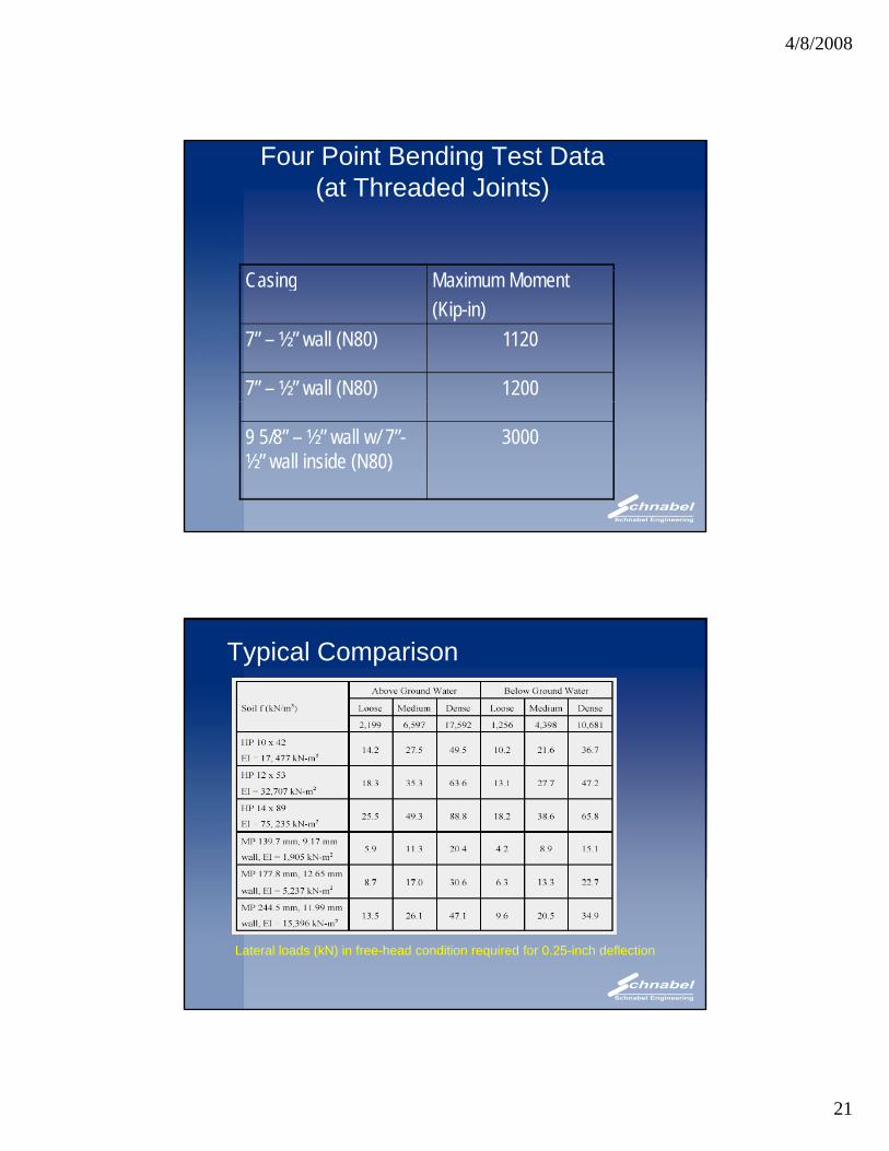
Four Point Bending Test Data(at Threaded Joints)
Casing Maximum Moment(Kip-in)
7” – ½” wall (N80) 1120
7” – ½” wall (N80) 1200
9 5/8” – ½” wall w/ 7”-½” wall inside (N80)
3000
Typical Comparison
Lateral loads (kN) in free-head condition required for 0.25-inch deflection
4/8/2008
22
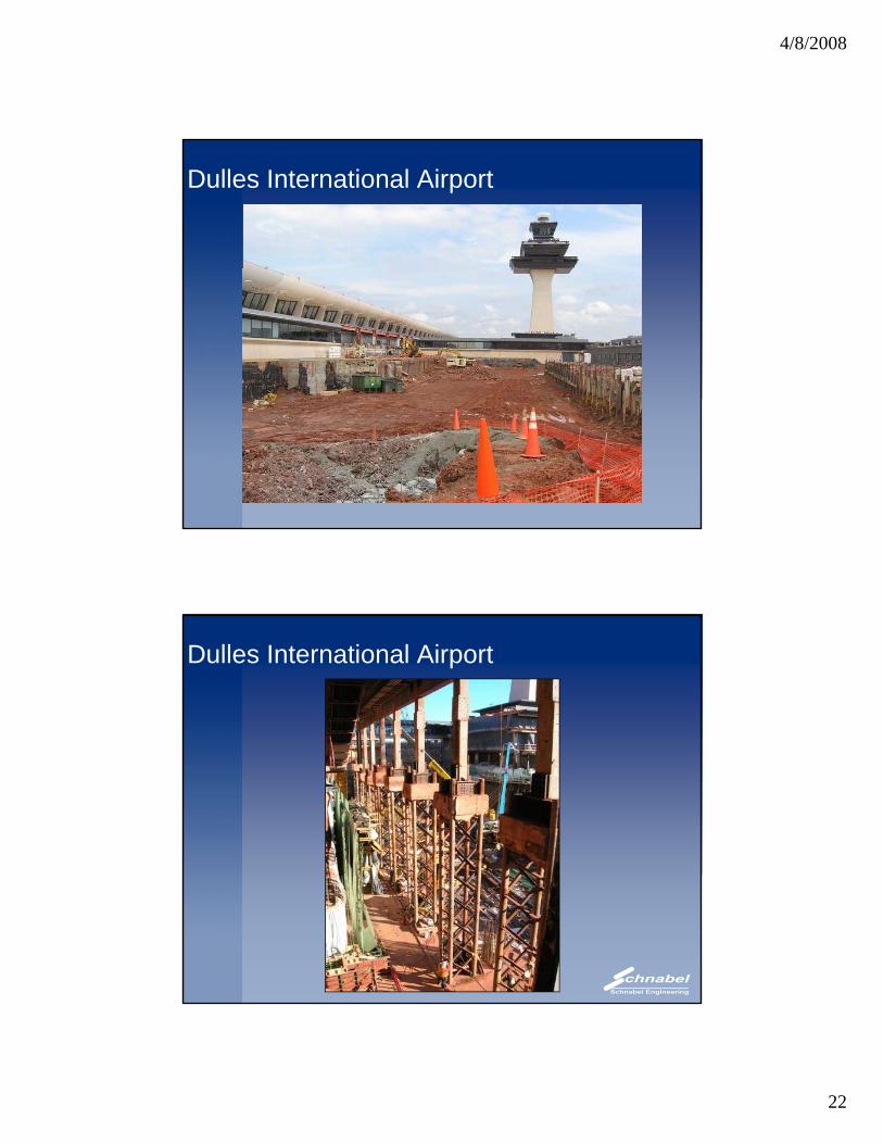
Dulles International Airport
Dulles International Airport
4/8/2008
23
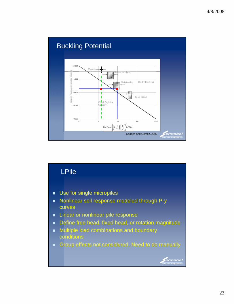
Buckling Potential
10.000
75-ksi barH ll b
L
0 010
0.100
1.000
tera
l Rea
ctio
n M
odul
us, c
(Ksi
)
80-ksi casing
36-ksi casing
Use Fy for design
Check Buckling Capacity
Es(ksi)
Hollow core bars
Lateral Reaction M
odulus, Es (ksi)
0.001
0.010
0.1 1 10 100 1000
Pile Factor, Fp (in2/Kip)
Lat p y
/kip)(infE
AI4FactorPile 2
2y
2⎥⎥⎥
⎦
⎤
⎢⎢⎢
⎣
⎡
⎟⎟
⎠
⎞
⎜⎜
⎝
⎛⋅⎟⎟
⎠
⎞⎜⎜⎝
⎛⋅
Cadden and Gómez, 2002
LPile
Use for single micropilesNonlinear soil response modeled through P-y curvesLinear or nonlinear pile responseDefine free head, fixed head, or rotation magnitudeMultiple load combinations and boundary p yconditionsGroup effects not considered. Need to do manually
4/8/2008
24
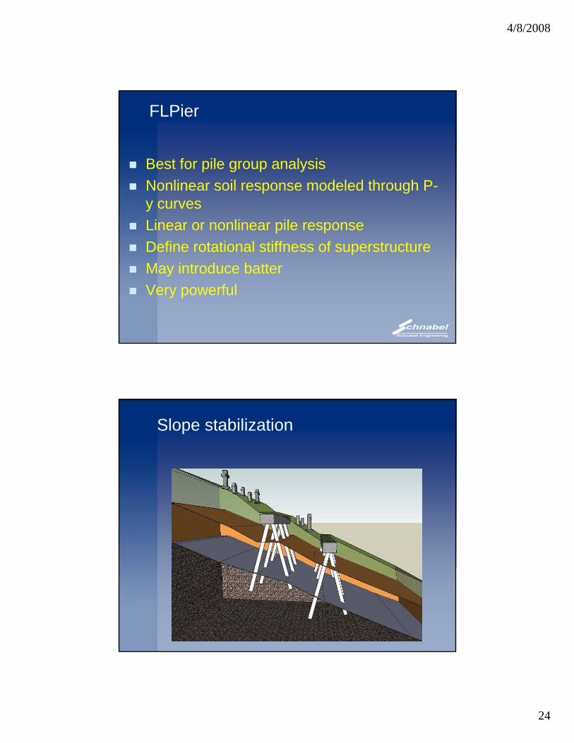
FLPier
Best for pile group analysisNonlinear soil response modeled through P-y curvesLinear or nonlinear pile responseDefine rotational stiffness of superstructureMay introduce batterVery powerful
Slope stabilization
4/8/2008
25
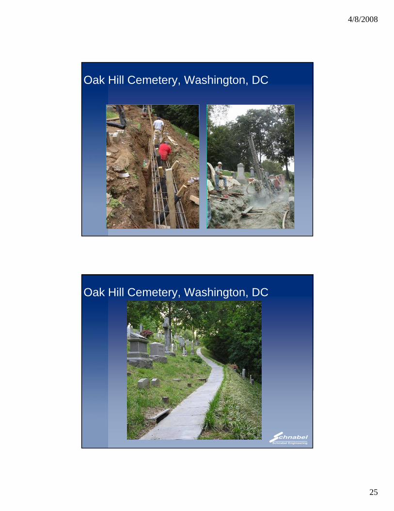
Oak Hill Cemetery, Washington, DC
Oak Hill Cemetery, Washington, DC
4/8/2008
26
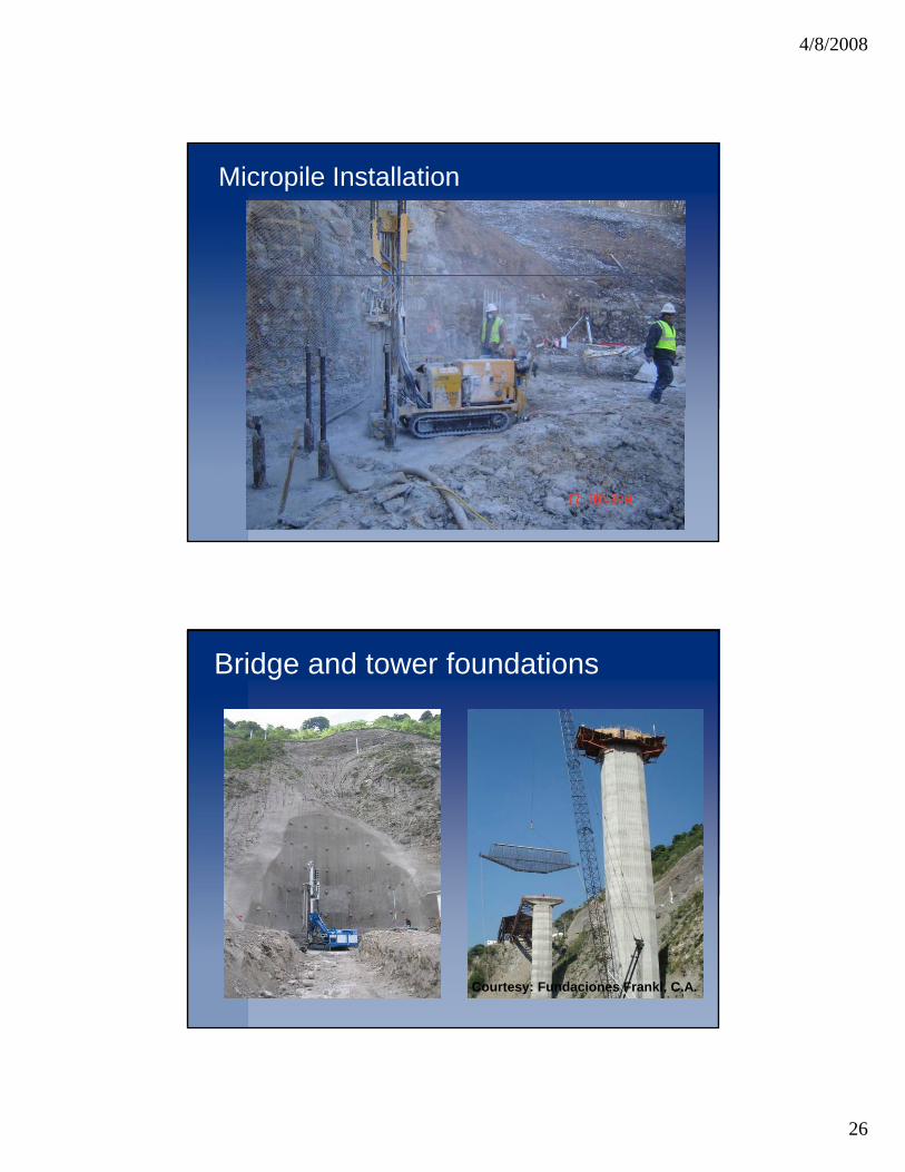
Micropile Installation
Bridge and tower foundations
Courtesy: Fundaciones Franki, C.A.
4/8/2008
27
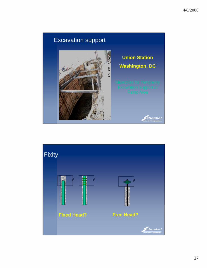
Excavation support
Union Station
Washington, DC
Micropiles for Temporary Excavation Support at
Ramp Areap
Fixity
Fixed Head? Free Head?
4/8/2008
28
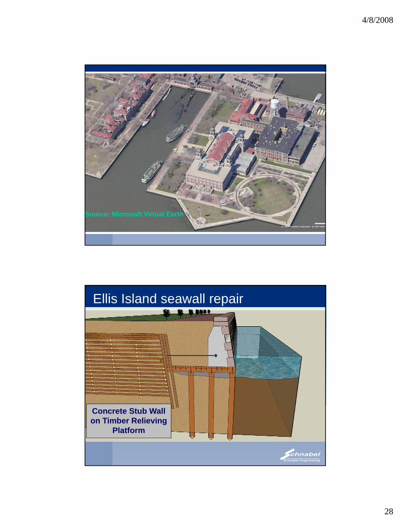
Source: Microsoft Virtual Earth
Ellis Island seawall repair
Concrete Stub Wall on Timber Relieving
Platform
4/8/2008
29
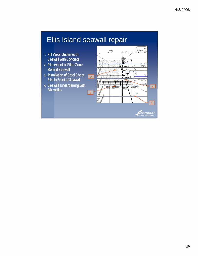
Ellis Island seawall repair
1. Fill Voids Underneath Seawall with Concrete
1. Fill Voids Underneath Seawall with ConcreteSeawall with Concrete
2. Placement of Filter Zone Behind Seawall
3. Installation of Steel Sheet Pile in Front of Seawall
4. Seawall Underpinning with Micropiles
Seawall with Concrete2. Placement of Filter Zone
Behind Seawall3. Installation of Steel Sheet
Pile in Front of Seawall4. Seawall Underpinning with
Micropiles
2
4MicropilesMicropiles
1
3