Embed Size (px)
Citation preview

Tramming a Bridgeport Mill By Tom Davis
Page 1 of 13 Procedure Developed By Brock Law
4/29/2007
Tramming A Bridgeport Mill
1. Tools Needed see Figure 1
a. Indicol type gage holder to fit the quill b. Last Word type gage c. Machinist square 4” or greater d. 12” long straight edge e. 123 Block f. Dead Blow hammer g. Table clamp set h. ¾” combination wrench i. Surface lapping plate
Figure 1 2. Insure the mill is set In The desired Location and Leveled

Tramming a Bridgeport Mill By Tom Davis
Page 2 of 13 Procedure Developed By Brock Law
4/29/2007
3. Check the flatness of the mill table see figure 2
a. Use the Surface lapping plate b. Slide the plate over the table surface in a figure 8 motion to check for table flatness. If corrections are needed, complete them before proceeding
Figure 2
4. Set the straight edge on the table parallel with the Y axis
a. Select a place on the table to place the straight edge b. Using the machinist square, align the straight edge perpendicular to the front edge of the table c. Using the clamp set, secure the straight edge to the table d. Attach the Indicol with the Last Word gage attached to the quill
a. See figure 3

Tramming a Bridgeport Mill By Tom Davis
Page 3 of 13 Procedure Developed By Brock Law
4/29/2007
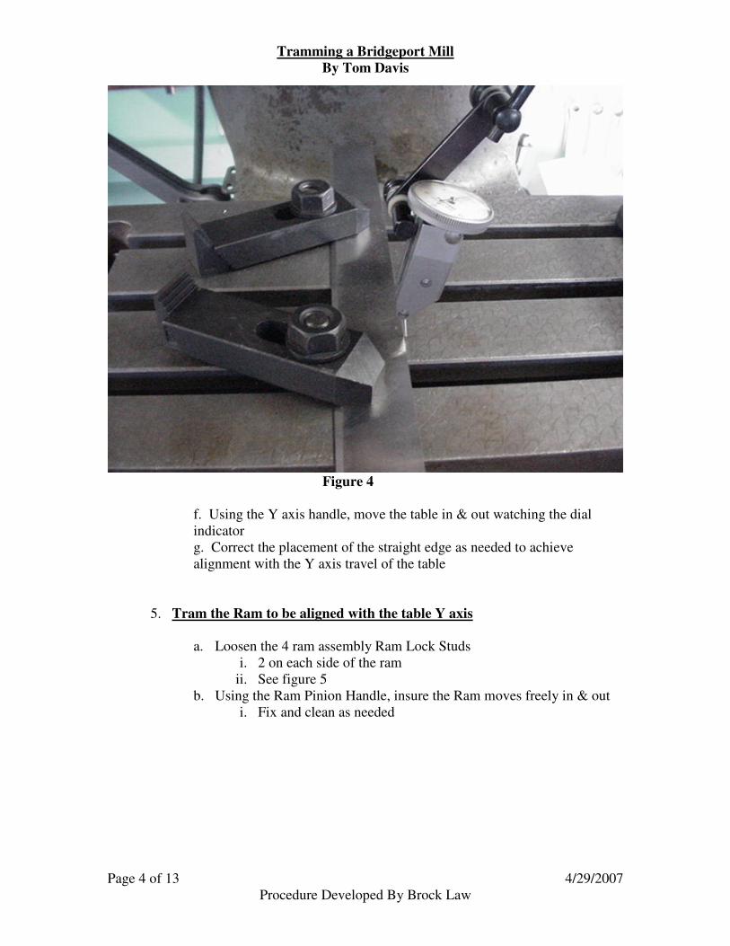
Figure 3
e. Raise the table to allow the last word tip to contact the edge of the straight edge
a. See figure 4
Tramming a Bridgeport Mill By Tom Davis
Page 4 of 13 Procedure Developed By Brock Law
4/29/2007
Figure 4 f. Using the Y axis handle, move the table in & out watching the dial indicator g. Correct the placement of the straight edge as needed to achieve alignment with the Y axis travel of the table
5. Tram the Ram to be aligned with the table Y axis
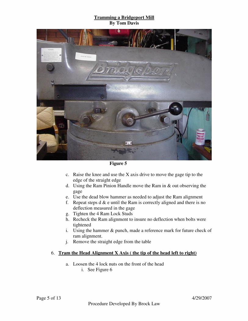
a. Loosen the 4 ram assembly Ram Lock Studs i. 2 on each side of the ram
ii. See figure 5 b. Using the Ram Pinion Handle, insure the Ram moves freely in & out
i. Fix and clean as needed
Tramming a Bridgeport Mill By Tom Davis
Page 5 of 13 Procedure Developed By Brock Law
4/29/2007
Figure 5 c. Raise the knee and use the X axis drive to move the gage tip to the
edge of the straight edge d. Using the Ram Pinion Handle move the Ram in & out observing the
gage e. Use the dead blow hammer as needed to adjust the Ram alignment f. Repeat steps d & e until the Ram is correctly aligned and there is no
deflection measured in the gage g. Tighten the 4 Ram Lock Studs h. Recheck the Ram alignment to insure no deflection when bolts were
tightened i. Using the hammer & punch, made a reference mark for future check of
ram alignment. j. Remove the straight edge from the table
6. Tram the Head Alignment X Axis ( the tip of the head left to right)
a. Loosen the 4 lock nuts on the front of the head
i. See Figure 6

Tramming a Bridgeport Mill By Tom Davis
Page 6 of 13 Procedure Developed By Brock Law
4/29/2007
Figure 6
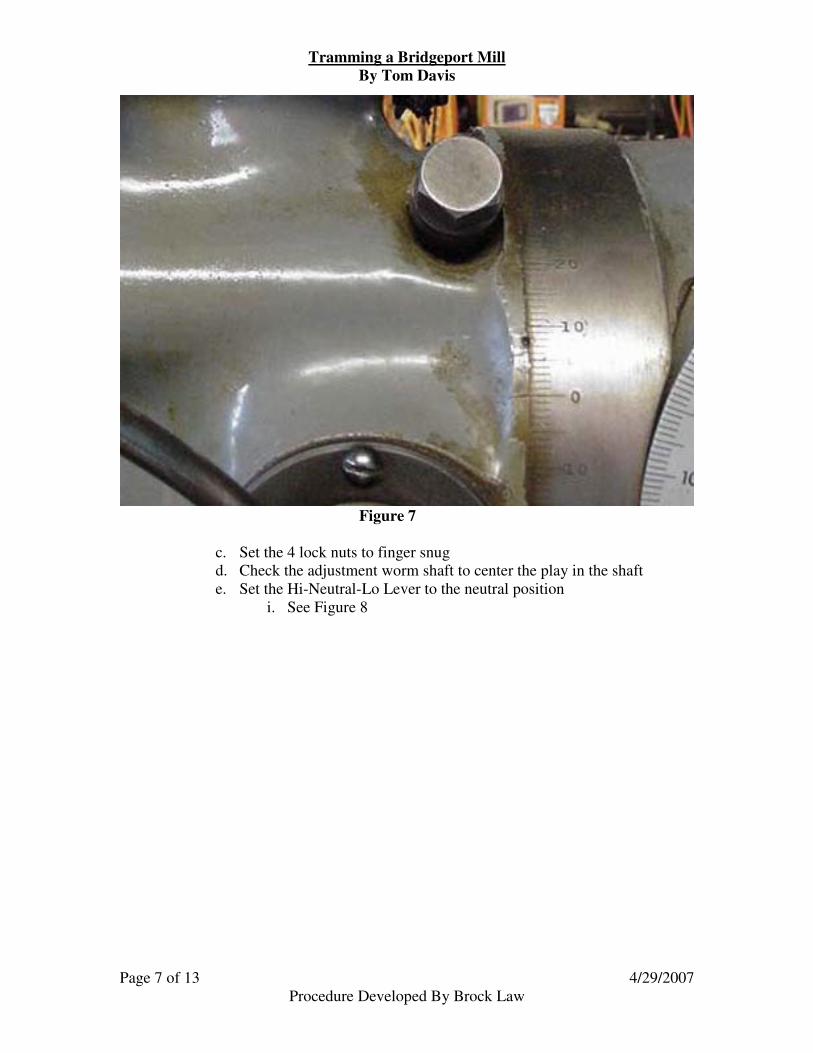
b. Using the Adjustment Worm Shaft move the head to a zero setting
i. See Figure 7
Tramming a Bridgeport Mill By Tom Davis
Page 7 of 13 Procedure Developed By Brock Law
4/29/2007
Figure 7
c. Set the 4 lock nuts to finger snug d. Check the adjustment worm shaft to center the play in the shaft e. Set the Hi-Neutral-Lo Lever to the neutral position
i. See Figure 8

Tramming a Bridgeport Mill By Tom Davis
Page 8 of 13 Procedure Developed By Brock Law
4/29/2007
Figure 8
f. Place the 123 block on the table at right center position of the tram
range g. Lower the knee to allow the gage tip to clear the 123 block h. Swing the indicator over the 123 block i. Raise the knee to bring the 123 block in contact with the indicator tip,
setting the gage to zero i. See Figure 9

Tramming a Bridgeport Mill By Tom Davis
Page 9 of 13 Procedure Developed By Brock Law
4/29/2007
Figure 9
j. Remove the 123 block and swing the gage 180 degrees k. Slide the 123 block under the gage tip l. Any deflection of the gage from the zero point indicates the head must
be aligned. m. Using the dead blow hammer, tap the head in the direction needed to
move the gage ½ the defection measured in step k n. Repeat steps f through l as needed to align the head in the X axis o. Tighten the 4 lock nuts on the front of the head p. Repeat steps f through k to insure the head did not shift when the lock
nuts were tightened. q. Using the hammer & punch make a reference mark for future check of
X axis alignment
7. Tram the head Alignment in the Y Axis (the tip of the head up & down)
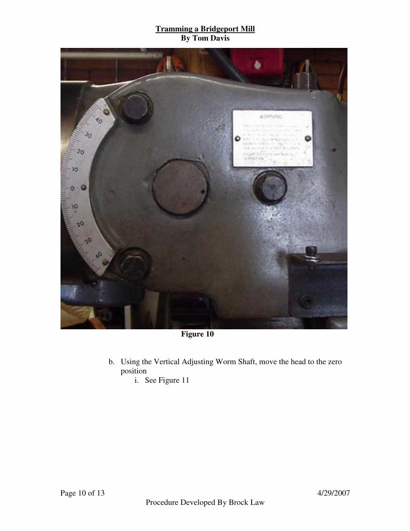
a. Loosen the 3 locking bolts on the left side of the Ram i. See Figure 10
Tramming a Bridgeport Mill By Tom Davis
Page 10 of 13 Procedure Developed By Brock Law
4/29/2007
Figure 10
b. Using the Vertical Adjusting Worm Shaft, move the head to the zero position
i. See Figure 11

Tramming a Bridgeport Mill By Tom Davis
Page 11 of 13 Procedure Developed By Brock Law
4/29/2007
Figure 11
c. Set the 3 locking bolts to just snug d. Set the Vertical Adjusting Worm Shaft play to the middle e. Set the Hi-Neutral-Lo Lever to the neutral position f. Place the 123 block at the right center position on the table g. Lower the knee to allow the gage tip to clear the 123 block h. Swing the gage over the 123 block i. Raise the knee to engage the tip of the gage and set the needle to zero j. Remove the 123 block k. Swing the gage to the front center position l. Slide the 123 block under the gage tip m. Using the Vertical adjusting worm shaft, move the head 80% of the
deflection difference between the front and right center position reading. Pivot point is well behind the table
n. Repeat steps f through l until there is no deflection between the 2 measurements
o. Remove the 123 block p. Swing the indicator to the rear center position q. Slide the 123 block under the indicator tip
i. If all is correct, this position should read zero r. Lower the knee one full turn s. Place the 123 block at the right center position on the table t. Swing the gage over the 123 block u. Raise the knee to engage the tip of the gage and set the needle to zero v. Repeat steps j through l in all 4 positions.
i. There should be no deflection in any position. w. Tighten the 3 locking bolts evenly x. Recheck front and rear center positions and Left and Right center
positions to insure the head did not shift when the bolts were tightened

Tramming a Bridgeport Mill By Tom Davis
Page 12 of 13 Procedure Developed By Brock Law
4/29/2007
8. If the mill vise is to be used, install it in the desired position now
9. Tram the fixed vise jaw to insure alignment with the X axis
a. Open the vise to allow the gage to fit easily between the jaws b. Place the Hi-Neutral-Lo switch in either Hi or Lo c. Loosen the vise mounting bolts to a snug hold d. Using the X, Y, and Z axis adjusting handles move the table to place
the tip of the gage to contact the face of the fixed vise jaw at the left end.
i. See Figure 12
Figure 12

Tramming a Bridgeport Mill By Tom Davis
Page 13 of 13 Procedure Developed By Brock Law
4/29/2007
e. Using the X axis handle move the table to the left across the length of the vise jaw observing the deflection if any on the gage
f. Using the dead blow hammer, move the vise to correct the alignment i. If you have a swivel base on the vise, move the vise ½ the
indicated deflection. Pivot point is in the center. ii. If you do not have a swivel base, move the vise all the
indicated deflection. Pivot point is on the zero end. g. Repeat steps c through e until there is no indicated deflection across
the vise jaw h. Tighten the vise hold down bolts i. Repeat steps c through d to insure the vise did not shift when the bolts
were tightened.
10. Remove the gage, Indicol, and other tools, and put them away