Embed Size (px)
Citation preview
Part Number 900-524 Revision B December 2007
XPort Direct+ Integration Guide/Data Sheet
XPort Direct+ Integration Guide/Data Sheet
2
Patents, Copyright and Trademark © 2007, Lantronix. All rights reserved. No part of the contents of this book may be transmitted or reproduced in any form or by any means without the written permission of Lantronix. Printed in the United States of America.
One or both of the following patents apply: 4,972,470 or 6,881,096. Other patents pending. XPort Direct+ with its patented technology is a trademark of Lantronix.
Ethernet is a trademark of XEROX Corporation. UNIX is a registered trademark of The Open Group. Windows 95, Windows 98, Windows 2000, Windows NT, and Windows XP are trademarks of Microsoft Corp. Netscape is a trademark of Netscape Communications Corporation.
Contacts Lantronix Corporate Headquarters 15353 Barranca Parkway Irvine, CA 92618, USA Phone: 949-453-3990 Fax: 949-453-3995
Technical Support Fax: 949-450-7226 Online: www.lantronix.com/support Email/Chat: www.lantronix.com/support
Sales Offices For a current list of our domestic and international sales offices go to the Lantronix web site at www.lantronix.com/about/contact/.
Disclaimer and Revisions Operation of this equipment in a residential area is likely to cause interference, in which case the user, at his or her own expense, will be required to take whatever measures may be required to correct the interference.
Note: This product has been designed to comply with the limits for a Class A digital device pursuant to Part 15 of FCC Rules. These limits are designed to provide reasonable protection against harmful interference in an industrial installation. This equipment generates, uses, and can radiate radio frequency This equipment generates, uses, and can radiate radio frequency energy, and if not installed and used in accordance with this guide, may cause harmful interference to radio communications.
Changes or modifications to this device not explicitly approved by Lantronix will void the user's authority to operate this device.
Note: With the purchase of XPort Direct+, the OEM agrees to an OEM firmware license agreement that grants the OEM a non-exclusive, royalty-free firmware license to use and distribute the binary firmware image provided, only to the extent necessary to use the XPort Direct+ hardware. For further details, please see the XPort Direct+ OEM firmware license agreement, see page 3.
Date Rev. Comments 10/07 A Initial release 12/07 B Edited warranty page

XPort Direct+ Integration Guide/Data Sheet 3
Contents Patents, Copyright and Trademark __________________________________________2 Contacts ______________________________________________________________2 Disclaimer and Revisions _________________________________________________2
1: Introduction 4 About the Integration Guide________________________________________________4 Additional Documentation _________________________________________________4
2: Description and Specifications 5 The XPort Direct+ _______________________________________________________5 XPort Direct+ Block Diagram_______________________________________________6 PCB Interface __________________________________________________________7 LEDs _________________________________________________________________8 Dimensions ____________________________________________________________9 Recommended PCB Layout ______________________________________________10 Demo Board Schematics_________________________________________________11 Technical Specifications _________________________________________________14
A: Compliance 17 B: Warranty 18
List of Figures Figure 2-1. Side View of the XPort Direct+ __________________________________5 Figure 2-2. XPort Direct+ Block Diagram ___________________________________6 Figure 2-3. RTS Connection for RS485 Mode ________________________________8 Figure 2-4. XPort Direct+ LEDs ___________________________________________8 Figure 2-5. Front View __________________________________________________9 Figure 2-6. Bottom View ________________________________________________9 Figure 2-7. Side View___________________________________________________10 Figure 2-8. PCB Layout (Top View) ________________________________________10 Figure 2-9. XPort Direct+ Demo Board _____________________________________11
List of Tables Table 2-1. PCB Interface Signals__________________________________________7 Table 2-2. Ethernet Interface Signals (Industry Standards)______________________8 Table 2-3. LEDs _______________________________________________________8 Table 2-4. Technical Specifications ________________________________________14
XPort Direct+ Integration Guide/Data Sheet 4
11:: IInnttrroodduuccttiioonn About the Integration Guide
This guide provides the information needed by engineers to integrate the XPort Direct™+ device networking gateway into their product.
Additional Documentation
The following documentation is available on the product CD and the Lantronix Web site (www.lantronix.com)
XPort Direct+ User Guide Provides information needed to configure, use, and update the XPort Direct+ firmware.
XPort Direct+ Quick Start Provides instructions for getting your unit up and running.
XPort Direct+ Integration Guide/Data Sheet 5
22:: DDeessccrriippttiioonn aanndd SSppeecciiffiiccaattiioonnss The XPort Direct+ embedded device server is a complete network-enabling solution enclosed within a compact, integrated package. This miniature serial-to-Ethernet converter enables original equipment manufacturers (OEMs) to quickly and easily go to market with networking and web page-serving capabilities built into their products.
The XPort Direct+
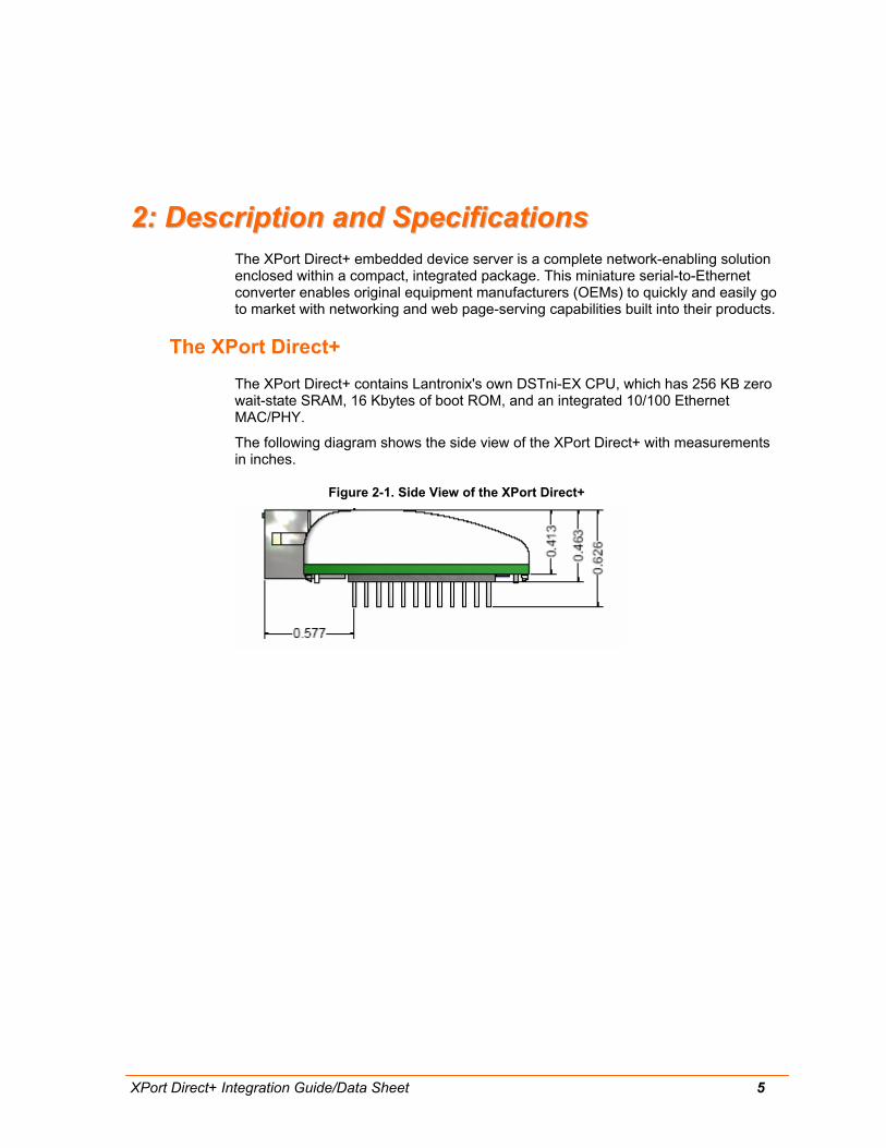
The XPort Direct+ contains Lantronix's own DSTni-EX CPU, which has 256 KB zero wait-state SRAM, 16 Kbytes of boot ROM, and an integrated 10/100 Ethernet MAC/PHY.
The following diagram shows the side view of the XPort Direct+ with measurements in inches.
Figure 2-1. Side View of the XPort Direct+
2:Description and Specifications
XPort Direct+ Integration Guide/Data Sheet 6
XPort Direct+ Block Diagram
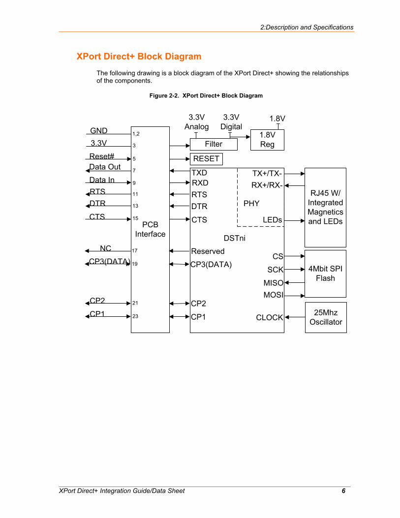
The following drawing is a block diagram of the XPort Direct+ showing the relationships of the components.
Figure 2-2. XPort Direct+ Block Diagram
TXDRXDRTSDTR
CTS
MOSIMISO
CS
SCK
TX+/TX-RX+/RX-
LEDs
CLOCK
PHY
DSTni
PCB Interface
Data Out
Data InRTSDTR
CTS
3.3VGND 1,2
3
7
9
11
13
15
CP3(DATA)
NC
CP1
CP2
17
19
21
23
Reset# 5 RESET
Filter
3.3V Analog
3.3V Digital
1.8V Reg
1.8V
CP1
CP2
Reserved
CP3(DATA) 4Mbit SPI Flash
RJ45 W/ Integrated Magnetics and LEDs
25Mhz Oscillator
2:Description and Specifications
XPort Direct+ Integration Guide/Data Sheet 7
PCB Interface
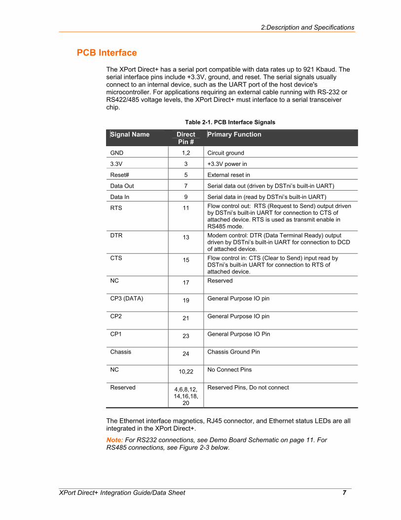
The XPort Direct+ has a serial port compatible with data rates up to 921 Kbaud. The serial interface pins include +3.3V, ground, and reset. The serial signals usually connect to an internal device, such as the UART port of the host device's microcontroller. For applications requiring an external cable running with RS-232 or RS422/485 voltage levels, the XPort Direct+ must interface to a serial transceiver chip.
Table 2-1. PCB Interface Signals
Signal Name Direct Pin #
Primary Function
GND 1,2 Circuit ground
3.3V 3 +3.3V power in
Reset# 5 External reset in
Data Out 7 Serial data out (driven by DSTni’s built-in UART)
Data In 9 Serial data in (read by DSTni’s built-in UART)
RTS 11 Flow control out: RTS (Request to Send) output driven by DSTni’s built-in UART for connection to CTS of attached device. RTS is used as transmit enable in RS485 mode.
DTR 13 Modem control: DTR (Data Terminal Ready) output driven by DSTni’s built-in UART for connection to DCD of attached device.
CTS 15 Flow control in: CTS (Clear to Send) input read by DSTni’s built-in UART for connection to RTS of attached device.
NC 17 Reserved
CP3 (DATA) 19 General Purpose IO pin
CP2 21 General Purpose IO pin
CP1 23 General Purpose IO Pin
Chassis 24 Chassis Ground Pin
NC 10,22 No Connect Pins
Reserved 4,6,8,12, 14,16,18,
20
Reserved Pins, Do not connect
The Ethernet interface magnetics, RJ45 connector, and Ethernet status LEDs are all integrated in the XPort Direct+.
Note: For RS232 connections, see Demo Board Schematic on page 11. For RS485 connections, see Figure 2-3 below.
2:Description and Specifications
XPort Direct+ Integration Guide/Data Sheet 8
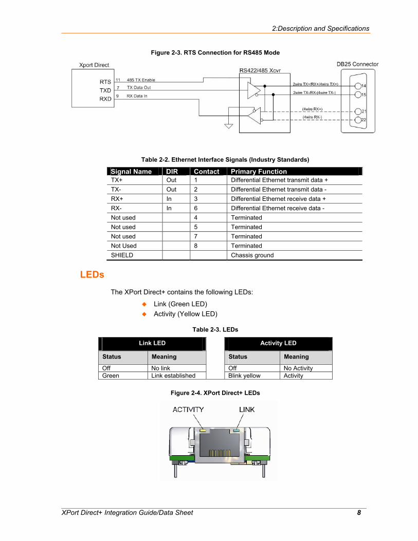
Figure 2-3. RTS Connection for RS485 Mode
Table 2-2. Ethernet Interface Signals (Industry Standards)
Signal Name DIR Contact Primary Function TX+ Out 1 Differential Ethernet transmit data + TX- Out 2 Differential Ethernet transmit data - RX+ In 3 Differential Ethernet receive data + RX- In 6 Differential Ethernet receive data - Not used 4 Terminated Not used 5 Terminated Not used 7 Terminated Not Used 8 Terminated SHIELD Chassis ground
LEDs
The XPort Direct+ contains the following LEDs:
Link (Green LED) Activity (Yellow LED)
Table 2-3. LEDs
Link LED Activity LED
Status Meaning Status Meaning
Off No link Off No Activity Green Link established
Blink yellow Activity
Figure 2-4. XPort Direct+ LEDs
2:Description and Specifications
XPort Direct+ Integration Guide/Data Sheet 9
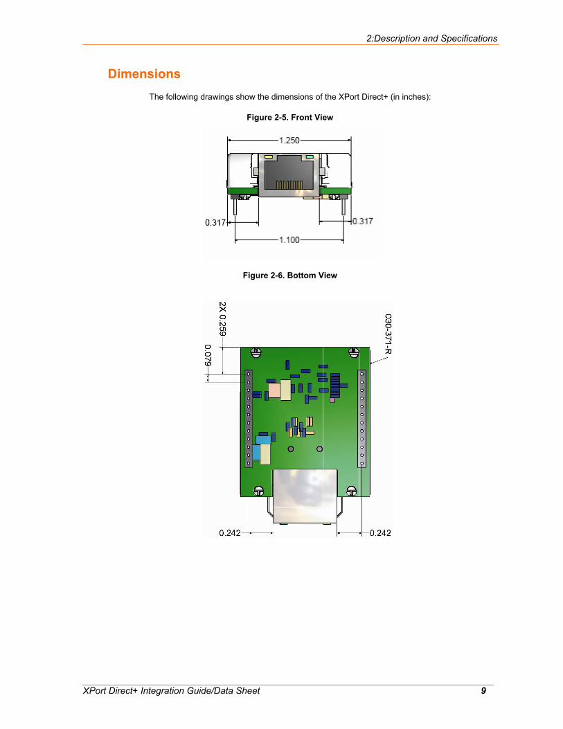
Dimensions The following drawings show the dimensions of the XPort Direct+ (in inches):
Figure 2-5. Front View
Figure 2-6. Bottom View
2:Description and Specifications
XPort Direct+ Integration Guide/Data Sheet 10
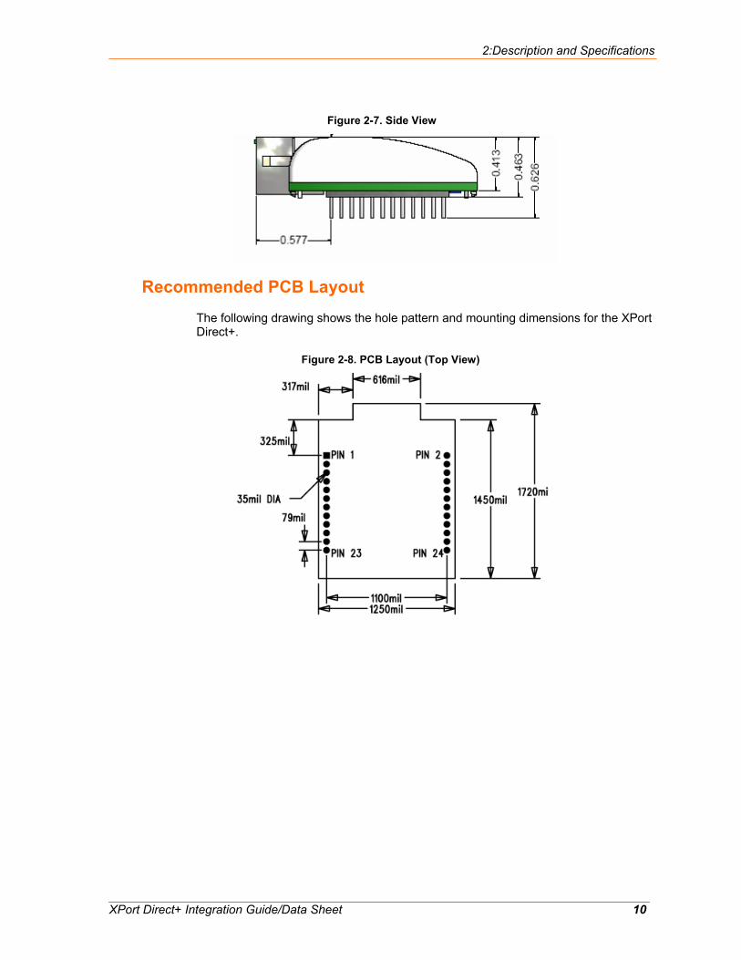
Figure 2-7. Side View
Recommended PCB Layout
The following drawing shows the hole pattern and mounting dimensions for the XPort Direct+.
Figure 2-8. PCB Layout (Top View)
2:Description and Specifications
XPort Direct+ Integration Guide/Data Sheet 11
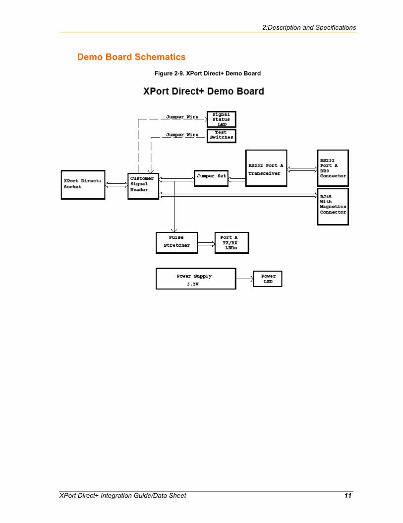
Demo Board Schematics Figure 2-9. XPort Direct+ Demo Board
2:Description and Specifications
XPort Direct+ Integration Guide/Data Sheet 12

2:Description and Specifications
XPort Direct+ Integration Guide/Data Sheet 13
2:Description and Specifications
XPort Direct+ Integration Guide/Data Sheet 14
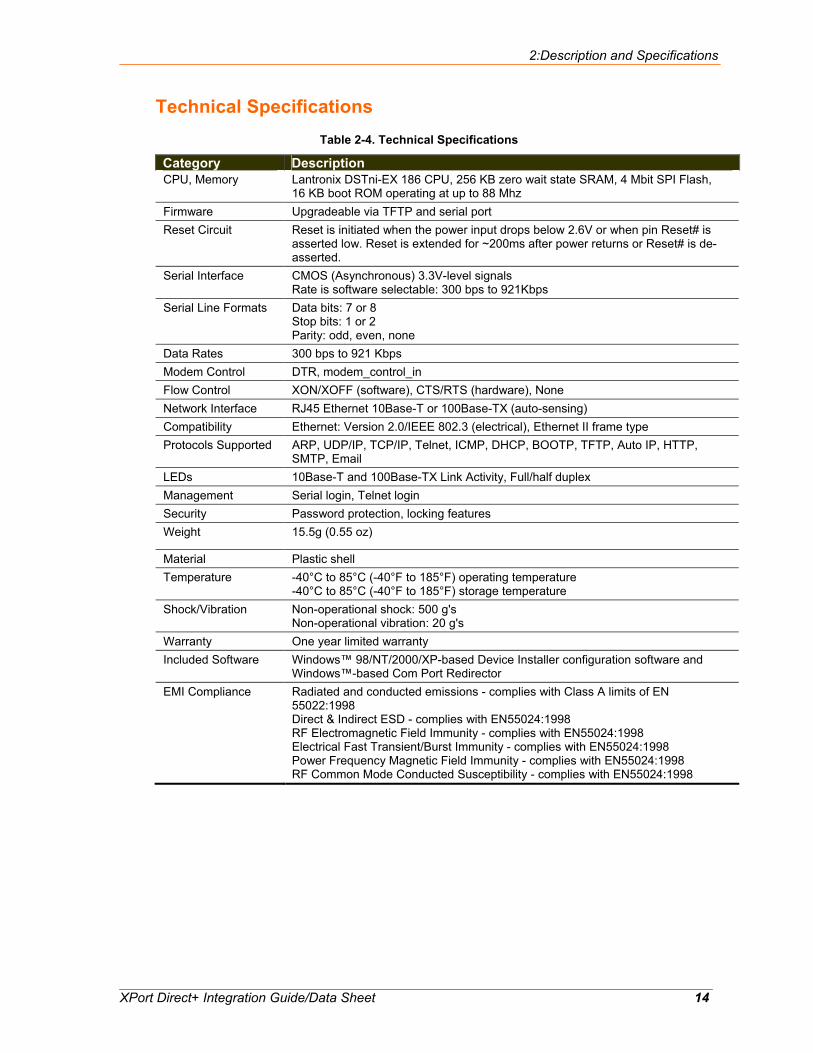
Technical Specifications Table 2-4. Technical Specifications
Category Description CPU, Memory Lantronix DSTni-EX 186 CPU, 256 KB zero wait state SRAM, 4 Mbit SPI Flash,
16 KB boot ROM operating at up to 88 Mhz Firmware Upgradeable via TFTP and serial port Reset Circuit Reset is initiated when the power input drops below 2.6V or when pin Reset# is
asserted low. Reset is extended for ~200ms after power returns or Reset# is de-asserted.
Serial Interface CMOS (Asynchronous) 3.3V-level signals Rate is software selectable: 300 bps to 921Kbps
Serial Line Formats Data bits: 7 or 8 Stop bits: 1 or 2 Parity: odd, even, none
Data Rates 300 bps to 921 Kbps Modem Control DTR, modem_control_in Flow Control XON/XOFF (software), CTS/RTS (hardware), None Network Interface RJ45 Ethernet 10Base-T or 100Base-TX (auto-sensing) Compatibility Ethernet: Version 2.0/IEEE 802.3 (electrical), Ethernet II frame type Protocols Supported ARP, UDP/IP, TCP/IP, Telnet, ICMP, DHCP, BOOTP, TFTP, Auto IP, HTTP,
SMTP, Email LEDs 10Base-T and 100Base-TX Link Activity, Full/half duplex Management Serial login, Telnet login Security Password protection, locking features Weight 15.5g (0.55 oz)
Material Plastic shell Temperature -40°C to 85°C (-40°F to 185°F) operating temperature
-40°C to 85°C (-40°F to 185°F) storage temperature Shock/Vibration Non-operational shock: 500 g's
Non-operational vibration: 20 g's Warranty One year limited warranty Included Software Windows™ 98/NT/2000/XP-based Device Installer configuration software and
Windows™-based Com Port Redirector EMI Compliance Radiated and conducted emissions - complies with Class A limits of EN
55022:1998 Direct & Indirect ESD - complies with EN55024:1998 RF Electromagnetic Field Immunity - complies with EN55024:1998 Electrical Fast Transient/Burst Immunity - complies with EN55024:1998 Power Frequency Magnetic Field Immunity - complies with EN55024:1998 RF Common Mode Conducted Susceptibility - complies with EN55024:1998
2:Description and Specifications
XPort Direct+ Integration Guide/Data Sheet 15
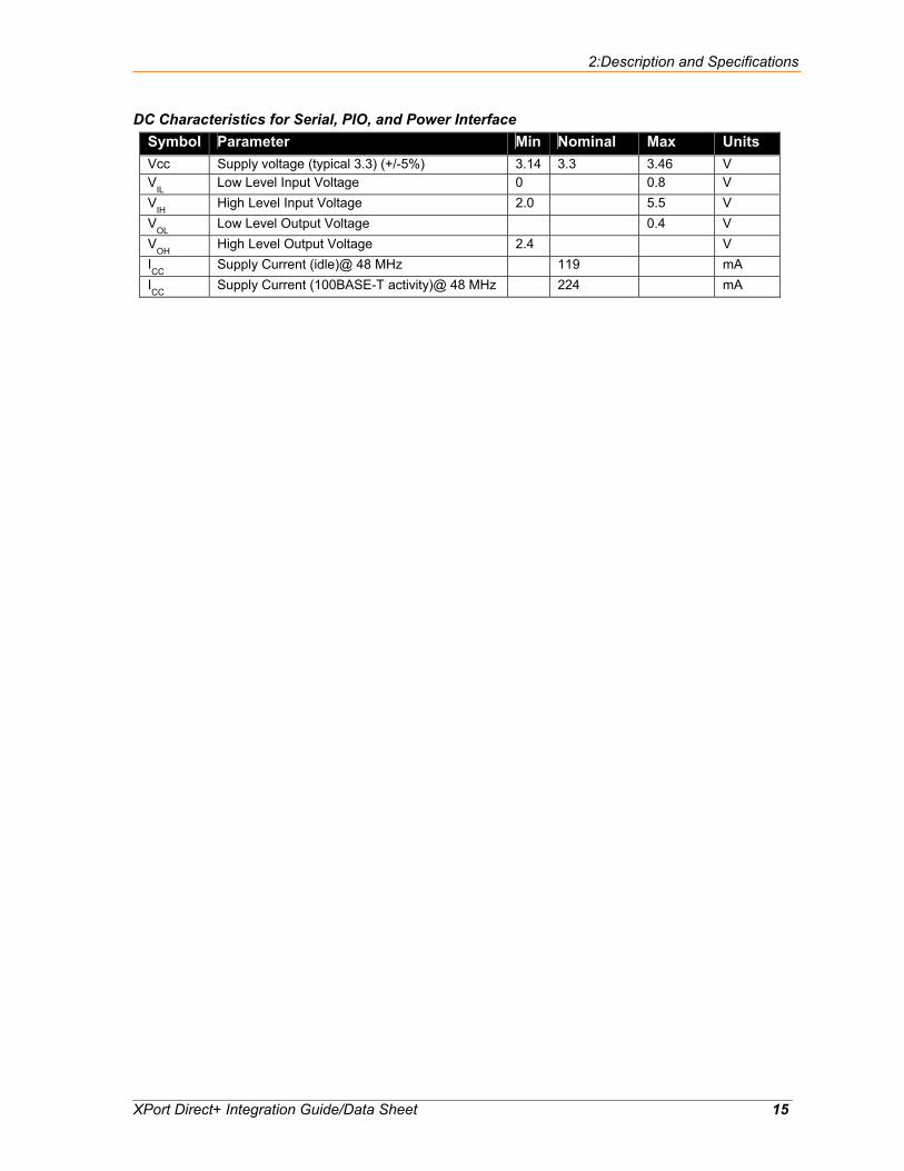
DC Characteristics for Serial, PIO, and Power Interface Symbol Parameter Min Nominal Max Units Vcc Supply voltage (typical 3.3) (+/-5%) 3.14 3.3 3.46 V V
IL Low Level Input Voltage 0 0.8 V
VIH
High Level Input Voltage 2.0 5.5 V V
OL Low Level Output Voltage 0.4 V
VOH
High Level Output Voltage 2.4 V ICC
Supply Current (idle)@ 48 MHz 119 mA ICC
Supply Current (100BASE-T activity)@ 48 MHz 224 mA
2:Description and Specifications
XPort Direct+ Integration Guide/Data Sheet 16
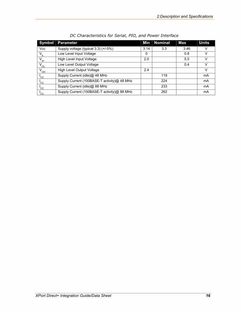
DC Characteristics for Serial, PIO, and Power Interface
Symbol Parameter Min Nominal Max Units Vcc Supply voltage (typical 3.3) (+/-5%) 3.14 3.3 3.46 V V
IL Low Level Input Voltage 0 0.8 V
VIH
High Level Input Voltage 2.0 5.5 V V
OL Low Level Output Voltage 0.4 V
VOH
High Level Output Voltage 2.4 V ICC
Supply Current (idle)@ 48 MHz 119 mA ICC
Supply Current (100BASE-T activity)@ 48 MHz 224 mA ICC
Supply Current (idle)@ 88 MHz 233 mA ICC
Supply Current (100BASE-T activity)@ 88 MHz 262 mA
XPort Direct+ Integration Guide/Data Sheet 17
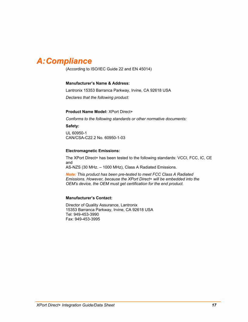
AA:: CCoommpplliiaannccee (According to ISO/IEC Guide 22 and EN 45014)
Manufacturer’s Name & Address:
Lantronix 15353 Barranca Parkway, Irvine, CA 92618 USA
Declares that the following product:
Product Name Model: XPort Direct+
Conforms to the following standards or other normative documents:
Safety:
UL 60950-1 CAN/CSA-C22.2 No. 60950-1-03
Electromagnetic Emissions:
The XPort Direct+ has been tested to the following standards: VCCI, FCC, IC, CE and AS-NZS (30 MHz. – 1000 MHz), Class A Radiated Emissions.
Note: This product has been pre-tested to meet FCC Class A Radiated Emissions. However, because the XPort Direct+ will be embedded into the OEM's device, the OEM must get certification for the end product.
Manufacturer’s Contact:
Director of Quality Assurance, Lantronix 15353 Barranca Parkway, Irvine, CA 92618 USA Tel: 949-453-3990 Fax: 949-453-3995

XPort Direct+ Integration Guide/Data Sheet 18
BB:: WWaarrrraannttyy For details on the Lantronix warranty replacement policy, go to our web site at www.lantronix.com/support/warranty.