Embed Size (px)
Citation preview
PDukeDEnergy®
Bryan J. DolanVP, Nuclear Plant Development
Duke EnergyECO9D/ 526 South Church StreetCharlotte, NC 28201-1006
Mailing Address:P.O. Box 1006 - ECO9DCharlotte, NC 28201-1006
704-382-0605
November 25, 2008
Document Control DeskU.S. Nuclear Regulatory CommissionWashington, DC 20555-0001
Subject:
Reference:
Duke Energy Carolinas, LLCWilliam States Lee III Nuclear Station - Docket Nos. 52-018 and 52-019AP1 000 Combined License Application for theWilliam States Lee III Nuclear Station Units 1 and 2Response to Request for Additional InformationLtr# WLG2008.11-26
Letter from J.M. Muir (NRC) to B.J. Dolan (Duke Energy), Request forAdditional Information Regarding the Environmental Review of theCombined License Application for William States Lee Nuclear StationUnits I and 2, dated August 21, 2008
This letter provides the Duke Energy response to the Nuclear Regulatory Commission's(NRC) requests for the following additional information (RAI) items listed in thereference letter:
RAI 11, HydrologyRAI 62, Hydrology
The response to these NRC requests is addressed in the enclosure which also identifiesany associated changes that will be made in a future revision of the William States LeeIII Nuclear Station application.
If you have any questions or need any additional information, please contact Peter S.Hastings at 980-373-7820.
&•naJnVice PresidentNuclear Plant Development
www.duke-energy.com

Document Control DeskNovember 25, 2008Page 3 of 4
AFFIDAVIT OF BRYAN J. DOLAN
Bryan J. Dolan, being duly sworn, states that he is Vice President, Nuclear PlantDevelopment, Duke Energy Carolinas, LLC, that he is authorized on the part of saidCompany to sign and file with the U. S. Nuclear Regulatory Commission thissupplement to the combined license application for the William States Lee III NuclearStation and that all the matter and facts set forth herein are true and correct to the bestof his knowledge.
Subscribed and sworn to me on !cLC -- ' •cQ
Notary Public
My commission expires: II'ULL'o- 9 L) cLODI
"SEAL,
t.-, , •'
Document Control DeskNovember 25, 2008Page 4 of 4
xc (wo/enclosure):
Michael Johnson, Director, Office of New ReactorsGary Holahan, Deputy Director, Office of New ReactorsDavid Matthews, Director, Division of New Reactor LicensingScott Flanders, Director, Division of Site and Environmental ReviewsGlenn Tracy, Director, Division of Construction Inspection and Operational ProgramsLuis Reyes, Regional Administrator, Region IILoren Plisco, Deputy Regional Administrator, Region IIThomas Bergman, Deputy Division Director, DNRLStephanie Coffin, Branch Chief, DNRLGregory Hatchett, Branch Chief, DSER
xc (w/enclosure):
Linda Tello, Project Manager, DSERBrian Hughes, Senior Project Manager, DNRL
/
Enclosure No. 1 Page 1 of 2Duke Letter Dated: November 25, 2008
Lee Nuclear Station Response to Request for Additional Information (RAI)
RAI Letter Dated: August 21, 2008
Reference NRC RAI Numbers: ER RAIs 11 and 62
NRC RAI:
ER RAI 11: Submit a discussion of the diffuser ports and sedimentation, and describesedimentation issues (and remedies) at Ninety-Nine Islands Dam in the vicinity ofthe planned construction and operation of the diffuser.
ER RAI 62: After Duke finishes their current study on sedimentation in the vicinity of Ninety- Nine Islands Dam, provide a copy of the report. This report should includeinformation on the expected frequency of dredging required near the discharge.
Duke Energy Response:
Sedimentation in the vicinity of the diffuser located on the Ninety-Nine Islands Dam is discussedbelow. The report on the sedimentation study is included herein as Attachment 11/62-1.
The exit velocity of wastewater from the discharge pipe is 1.6 ft/s for one unit and 3.2 ft/s fortwo units, which is 16,000 and 32,000 times greater than the settling velocity, respectively. Thecalculated settling velocity of sediment typical of that found in Ninety-Nine Islands Reservoir instill water is approximately 0.0001 feet per second (ft/s). As a result, sediment should not settleon the discharge pipe during normal Lee Nuclear Station operations.
Two cases were evaluated to determine if the discharge pipe is susceptible to sediment buildup inthe event that both units of the Lee Nuclear Station were shutdown. The two cases evaluatedwere: (1) one unit of Ninety-Nine Islands Hydro operating and (2) no hydro units operating.
Under one-unit hydro generation, velocities near the diffuser end of the wastewater dischargepipe range from 0.25 to 1.0 ft/s, which should be adequate to prevent sediment from settling onthe pipe.
Under the no hydro generation scenario, a hydraulic eddy forms in the area of the wastewaterdischarge pipe and sediment deposition during these periods may occur. It should be noted thateven under the no hydro generation scenario, leakage occurs through the hydro units' wicketgates therefore some continuous flow will always be released from the units but this flow isbeing ignored for this evaluation. Based on the configuration of Ninety-Nine Islands Reservoirand the bathymetry of the reservoir near the dam, it is likely that the majority of sediments willsettle out along the deepest portion of the reservoir forebay away from the diffuser end of thepipe.
If some settling of sediment does occur on the diffuser end of the wastewater discharge pipe, itwill likely dissipate rapidly once Ninety-Nine Islands Hydro returns to operation or wastewateris discharged through the 1-inch-diameter holes along the last 65-ft of pipe. This is because bothhydro generation velocities (0.25 ft/s to 1.0 ft/s) and wastewater discharge velocities (1.6 ft/s to3.2 ft/s) greatly exceed the settling velocity of medium grade silt particles (0.0001 ft/s). As a
Enclosure No. 1Duke Letter Dated: November 25, 2008
Page 2 of 2
result, there should be minimal risk of having to dredge out the diffuser end of the pipe fromsediment loading during a shutdown of both units of the Lee Nuclear Station.
Associated Revisions to the Lee Nuclear Station Combined License Application:
None
Associated Attachment:
Attachment 11/62-1: Discharge Pipe Sedimentation Analysis Report. Prepared by DevineTarbell & Associates, Inc., November 21, 2008.

Devine Tarbell &.Associates, Inc.TA Consulting Engineers, Scientists, & Regulatory Specialists
An Employee-Owned Company
November 21, 2008
Mr. Dale SmithNuclear Special ProjectsDuke Energy Carolinas, LLC526 S. Church StreetCharlotte, NC 28202
Subject: Proposed William States Lee III Nuclear StationDischarge Pipe Sedimentation Analysis Report
Dear Mr. Smith:
The proposed William States Lee III Nuclear Station (LNS) is located on the Broad River inCherokee County, North Carolina. Under normal station operations, LNS will dischargewastewater via a submerged diffuser pipe directly into the forebay of Ninety-Nine IslandsHydroelectric Station. The proposed location of the outfall is along the upstream face of Ninety-Nine Islands Dam near the intake structure of Ninety-Nine Islands Hydro. Devine Tarbell &Associates, Inc. (DTA) was enlisted by Duke Energy Carolinas, LLC (Duke) to analyzesedimentation issues near the diffuser pipe to determine if the pipe would be susceptible to beingburied in sediment during normal operations and during prolonged periods of non-operation ofboth units due to an extended outage.
1.0 Diffuser Pipe Description and Operation
The proposed wastewater discharge pipe will be attached to the upstream face of Ninety-NineIslands Dam and run the entire length of the dam (approximately 925 ft), ending just before theintake structure of Ninety-Nine Islands Hydroelectric Station (reference attached Figure 1). Thecenterline of the 3-ft diameter discharge pipe will be 6 ft below the full pond elevation of Ninety-Nine Islands Reservoir. As a result, the top of the discharge pipe will be 4.5 ft below full pond.The last 65 ft of the discharge pipe will be perforated with 1-inch-diameter holes and the end ofthe pipe will be capped, which will create a diffuser effect at the outfall. The 1-inch-diameterholes will only be on the upstream facing portion of the pipe. Thus, wastewater will bedischarged directly into the forebay and not into, the upstream face of the dam. From thecenterline of the pipe, the 1-inch-diameter holes will be 3 inches on center. There will be tworows of holes above the centerline of the pipe and two rows below the centerline of the pipe.Based on this configuration, there will be 16 1-inch-diameter holes per linear foot of pipe. In all,there will be 1,040 1-inch-diameter holes covering the last 65 ft of discharge pipe.
T: 704.377.4182 400 S. Tryon Street, Suite 2401, Charlotte, NC 28285 F: 704.377.4185
Portland, ME Charlotte, NC I Sacramento, CA I York, PA I Syracuse, NY I Seattle, WA Bellingham, WA I Boise, ID Toronto, ON
www.levineTarbell.com . .." t , . :
Mr. Dale SmithNovember 21, 2008DPage 2
During normal operations of both units at the proposed LNS, 18.5 cubic feet per second (cfs) ofstation blowdown will be routed through the wastewater discharge pipe and enter Ninety-NineIslands Reservoir as described above. Assuming uniform flow from each hole, the calculatedinitial exit velocity of wastewater through the diffuser is approximately 3.2 feet per second (ft/s)as shown in the equation below:
18.5 ft3 18.5 ft 3
Flow _Flow 1. _
Velocity = 3.21f__fi tArea (#Holes X)Xradius)2 -,2 5"7ft2 S
(1,040);{o.5inj 57i
2.0 Sediment Deposition During Normal Station Operations
During normal station operations of both units, 23 cfs will be withdrawn for intake screen washand other non-consumptive plant uses. Approximately 4.5 cfs will be used for screen wash andthe remaining 18.5 cfs will be returned as wastewater and will be continuously dischargedthrough the 65 ft long diffuser section of pipe at an initial exit velocity of 3.2 ft/s. For one unit,initial exit velocity will be 1.6 ft/s.
Duke Environmental Health & Safety personnel collected total suspended sediment (TSS)samples from Ninety-Nine Islands Reservoir on a twice per month basis during 2007. Sampleswere collected at two locations upstream from the intake structure. At each location, sampleswere collected at 0.3 meter depth, 3 meter depth, and near the bottom of the reservoir. Thesesamples were analyzed by Duke's certified water quality laboratory to determine TSS, expressedas a dry weight in mg/L. The range of TSS captured during the 2007 sampling events was lessthan 4 to 204 mg/L.
Texas Oil Tech Laboratories in Houston, Texas, performed further analysis of individual particlesizes captured during three of the monthly sampling events. The three sampling events that wereanalyzed represented the highest, middle, and lowest monthly TSS sampling events during 2007.In all, five individual samples collected during these three sampling events were analyzed.Based on the analysis performed by Texas Oil Tech Laboratories, the range of particle sizes wasfrom 0.00035 mm (typical of clay particles) to 0.35355 mm (typical of medium grade sand). Themedian particle size for all five samples was 0.0120 mm, 0.0209 mm, 0.0189 mm, 0.0185 mm,and 0.0151 mm (all typical of fine to medium grade silt). The average of these median particlesizes was 0.0171 mm (typical of medium silt).
Settling velocity of small particles (medium silt) in a viscous fluid (water) is governed byStokes' Law, which is defined as:
Mr. Dale SmithNovember 21, 2008Page 3
_ 2 (P, -P,.)gR29 /U
where:V, is the particle's settling velocity (m/s)g is the gravitational acceleration (mis 2)PP is the mass density of the particles (kg/m3)pf is the mass density of the fluid (kg/mr3)ji is the fluids dynamic viscosity (Pa s)R is the radius of the spherical particle (m)
For our purposes:G = 9.81m/s
2
pp= 1150kg/mr3
pf = 995.2 kg/m 3 (at 30 deg C)ýt = 0.000798 Pa s (at 30 deg C)R = 0.0000086 m
Solving Stokes' Lawequation:
2. (1150-995.2) 9.81 (0.0000086)2 0.0000309m/ s(3"288ft 00001f/s
9 0.000798 -Km )
The calculated settling velocity of medium-sized silt particles in still water is approximately0.0001 ft/s. The exit velocity of wastewater from the discharge pipe is 3.2 ft/s, which is 32,000times greater. As a result, sediment typical of that found in Ninety-Nine Islands Reservoirshould not settle on the discharge pipe during normal station operations at LNS.
3.0 Sediment Deposition during Station Shutdown
DTA also analyzed the case of sediment deposition during station shutdown. In order tomaximize the amount of sediment that could deposit on the discharge pipe, it was assumed thatboth LNS units would be off-line for 4 months or 120 days. The next step of this analysis was todetermine if the wastewater discharge pipe is susceptible to being buried in sediment duringthese prolonged periods of no station operations at LNS. Station operations at Ninety-NineIslands Hydro were also factored into this analysis. Two scenarios were evaluated: one withstation operations at Ninety-Nine Islands Hydro and one without hydro operations. It should benoted that under a low flow condition where Ninety-Nine Islands is operating to pass inflowscoming in to the reservoir, a hydro unit is pulsed every hour to pass the inflows so there shouldnot be a case of no hydro operations resulting in spilling over the dam. However to evaluate themost conservative case, it was assumed that the hydro units are not operating.
Mr. Dale SmithNovember 21, 2008Page 4
Figures 2 and 3 depict velocity vectors in Ninety-Nine Islands Hydro forebay in the area of theproposed wastewater discharge pipe. Figure 2 shows velocity conditions with one hydro unit inoperation and Figure 3 shows velocity conditions with no hydro units in operation. Thesemeasurements were made in August 2007 by DTA personnel using an Acoustic Doppler CurrentProfiler (ADCP).
Under one-unit hydro generation (Figure 2), velocities near the diffuser end of the wastewaterdischarge pipe range from 0.25 to 1.0 ft/s, which should be adequate to prevent sediment fromsettling on the pipe when the pipe is not discharging wastewater.
Under the no hydro generation scenario (Figure 3), a hydraulic eddy forms in the area of thewastewater discharge pipe and sediment deposition during these periods may occur. It should benoted that even under the no hydro generation scenario, leakage occurs through the hydro units'wicket gates. This is being ignored for this analysis. In order to determine how much sedimentmay be available during these low flow periods, TSS versus flow data was plotted for 2007 (theyear in which twice per month TSS data was collected). This relationship is shown in Figure 4.For flows less than 1,800 cfs, it was conservatively assumed that TSS = 20 mg/L based on thefield data collected during 2007. For flows higher than 1,800 cfs, Microsoft Excel software wasused to determine a linear equation for the relationship between flow and TSS. The resultingequation is:
Y =0.0135X - 4.8793
where:Y is TSS in mg/L, andX is flow in cfsThe R-squared value for this equation is 0.86
Using this relationship, daily TSS values were determined for 8/1/2002 to 11/29/2002. Theresulting daily TSS values are provided in the attached Table 1. Using both the daily averageflow rate and corresponding TSS concentration, daily mass loading rates were calculated and areprovided in Table 1. Note that this analysis conservatively assumes that 100 percent of thesediment entering Ninety-Nine Islands Reservoir over the 120-day period analyzed depositsdirectly in front of Ninety-Nine Islands Dam near the proposed location of the wastewaterdischarge pipe. Using this methodology, the total volume of sediment entering the reservoir overthe 120-day period is 6,280 m3 (or 8,214 yd 3; or 221,743 ft3).
Under the conservatively assumed no hydro generation scenario, flows through Ninety-NineIslands Reservoir will spill over the dam. Based on the configuration of Ninety-Nine IslandsReservoir and the bathymetry of the reservoir near the dam, it is likely that the majority ofsediments will settle out along the deepest portion of the reservoir forebay (Figure 5)., Forconservatism, this analysis assumes that 100 percent of the sediment will deposit in this area overthe 120-day period. Figure 6 is a cross-section of the reservoir forebay and shows the area where

Mr. Dale SmithNovember 21, 2008Page 5
sediments are likely to settle out of the water column. Using Geographic Information System(GIS) software to determine the overall capacity of the reservoir forebay to contain additionalsediment loads, it appears that the entire 6,280 m3 of sediment can be contained at the bottom ofthe forebay below the wastewater discharge pipe. Also, note that the area where settling is mostlikely to occur is away from the diffuser end of the pipe. Therefore, it is unlikely that thediffuser end of the pipe will be buried in sediment during extended outage conditions.
If some settling of sediment does occur on the diffuser end of the wastewater discharge pipe, itwill likely dissipate rapidly once Ninety-Nine Islands Hydro returns to operation or wastewateris discharged through the 1-inch-diameter holes along the last 65-ft of pipe. This is because bothhydro generation velocities (0.25 ft/s to 1.0 ft/s) and wastewater discharge velocities (3.2 ft/s)greatly exceed the settling velocity of medium grade silt particles (0.0001 ft/s). As a result, thereshould be minimal risk of having to dredge out the diffuser end of the pipe from sedimentloading during extended outage conditions.
This report provides the results of DTA's analysis regarding sedimentation issues near theproposed wastewater diffuser pipe using readily available data and analysis as described above.Should you have any questions regarding this submittal or require further information, pleasecontact me at (704) 342-7381 or ty.ziegler~devinetarbell.com.
Sincerely,
DEVINE TARBELL & ASSOCIATES, INC.
Ty Ziegler, P.E. Carey Fraser Justin Schumacher, E.I.T.Environmental Engineering Manager Technical Editor Associate Engineer
TKZ/cefAttachments
cc: T. Bowling, Duke EnergyJ. Thrasher, Duke EnergyFile
ATTACHMENTS

FIGURE 1NINFTV.NINF III.ANnq FPORFRAV CROSS-SFCTION PRnFI1E SH-OWINC IOCATION OF WASTFWATF.R DISCIIARCF PIPF
I
520 - 511.1 Fullpond Elevation510 -
500 Aa a_ - -490 , -"
490~DMSE ENDa fInae PROPOSEDLOCATIONOF480; -•TC D11E WAs'T'w''iT n-gamr PwT
480 HOLES PER liNEAR FO0fl3~FT DIAMETER • T•H CEN•MUIThE
470 - FT BELOW MfL1 POND EUVATION)
460 3100 300 500 700 900 1 100 1 30 a0
Dlstance (fet)
Nuiery-Nmie Islands Forebay Cross-Section ProfileBottom elevations measwued 2007. Contours in feet mean sea level.

FIGURE 2
WATER VELOCITY VECTORS IN LOWER NINETY-NINE ISLANDS RESERVOIR WITH ONE UNIT OPERATINGF,
Averaged flow velocity and directionfeet/sec
t - 0.25
t 026- 0.50
t 0.51 - 0.75
* 0.76-1.00
0 ADCP sampling points

FIGURE 3
WATER VELOCITY VECTORS IN LOWER NINETY-NINE ISLANDS RESERVOIR WITH NO UNITS OPERATING
AvragIed flow vulocity and directionfeet/sec
1 - 0.05
t 0.05-0.10
t 0.10- 0-20
t 0.20- 0.40
. ADCP sampling points

FIGURE 4
NINETY-NINE ISLANDS RESERVOIR TSS VERSUS FLOW RELATIONSHIP
50
45
40
35
3 0 -------
25
20
15Sy 0.0135x - 4.8793
R 2 =0.8642
10
0,0 500 1000 1500 2000 2500 3000 3500 4000
Flow (cfs)
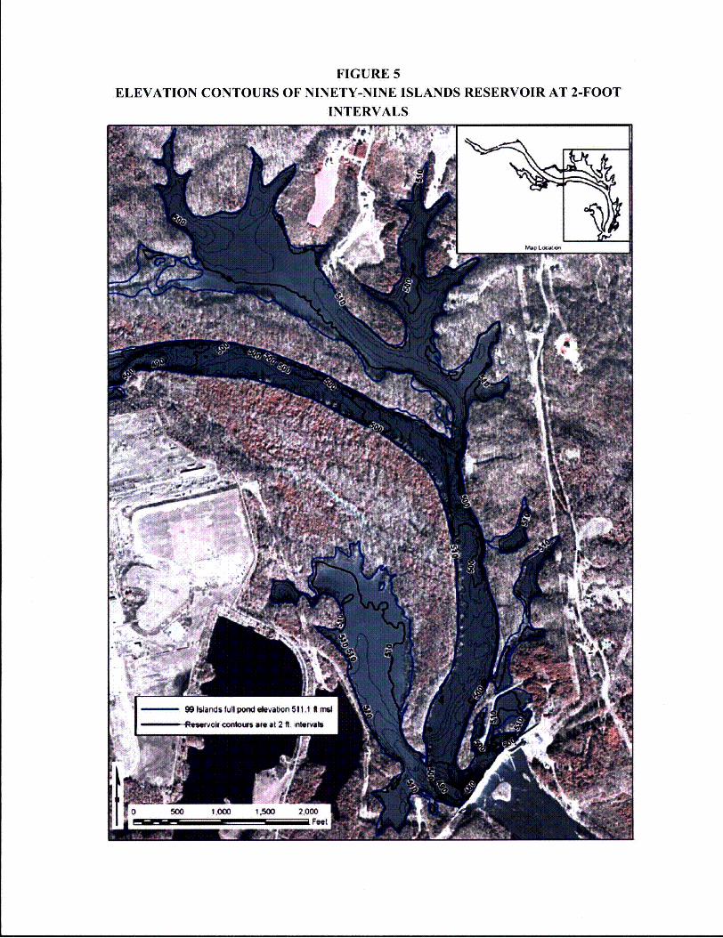
FIGURE 5
ELEVATION CONTOURS OF NINETY-NINE ISLANDS RESERVOIR AT 2-FOOT
INTERVALS
- 99 Iiands ful pod levatign 511.1 A mi
.. M air/ cmnloa are at 2 ft. indrval
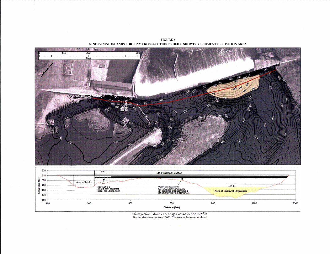
FIGURE 6
NINETY-NINE ISLANDS FOREBAY CROSS-SECTION PROFILE SHOWING SEDIMENT DEPOSITION AREA
520
510
sw
490
470
460
soft511T FiiUaO1EBevatcio
TArea of Inake . 9-- "/1N._ Dunt5mm PJD MPOSM LOCATION ~4~~~~ ~~WASTEWUDISCHARG~E PM~__________
soMV F Tu •p m• cR'n• Area of Sedament Depono6 W ELU. P0.fl aa LUp a,"a O .%)
100 3V0 700Destance (feet)
900 1100 1300
Ninety-Nine Islands Forebay Cross-Scetion ProfileBottom ele atsons measured 2007. Contours in feet mean sea level.
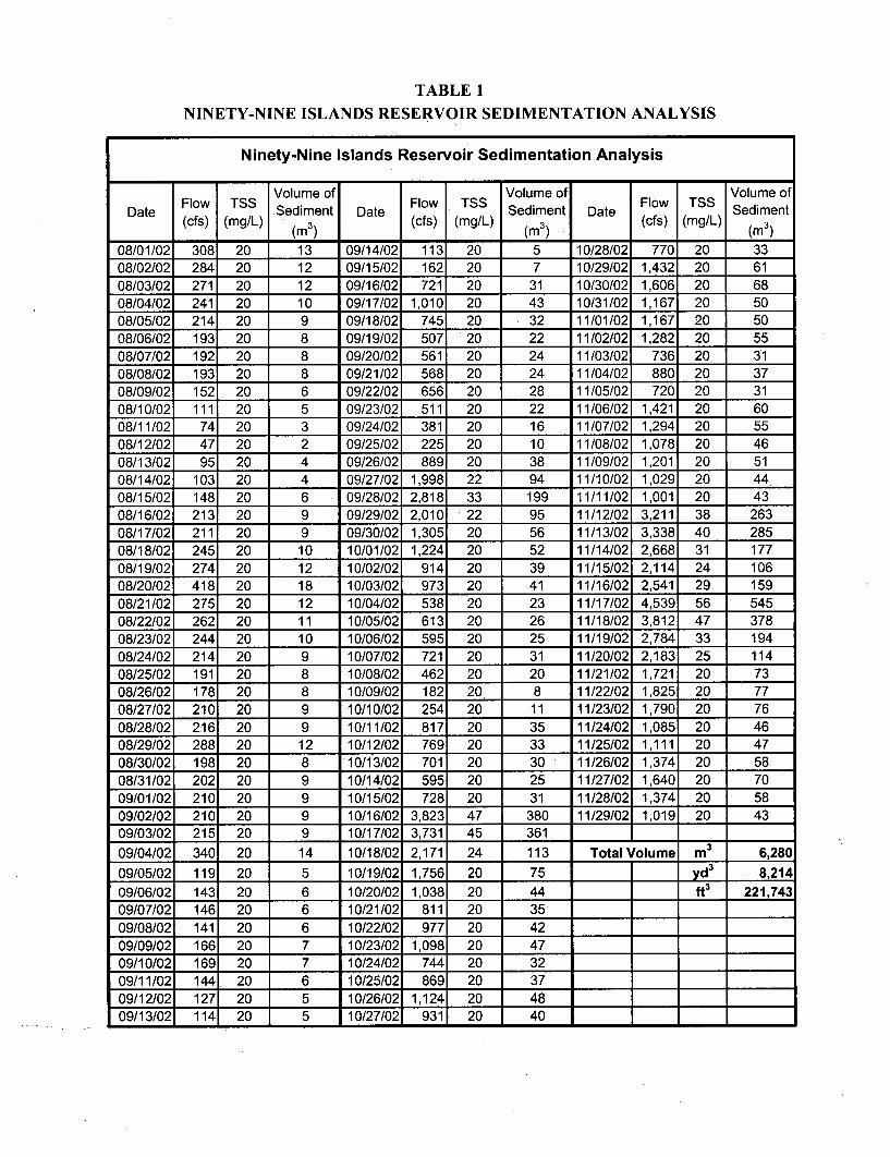
TABLE I
NINETY-NINE ISLANDS RESERVOIR SEDIMENTATION ANALYSIS
Ninety-Nine Islands Reservol r Sedimentation Analysis
Flow TSS Volume of Flow TSS Volume of Flow TSS Volume ofDate Sediment Date Sediment Date Sediment
(cfs) (mg/L) (cfs) (mg/L) (cfs) (mg/L)(m) (M) (M)
08/01/02 308 20 13 09/14/02 113 20 5 10/28/02 770 20 3308/02/02 284 20 12 09/15/02 1621 20 7 10/29/021 1,432 20 6108/03/02 271 20 12 09/16/02 721 20 31 10/30/02 1,606 20 6808/04/02 241 20 10 09/17/02 1,010 20 43 10/31/02 1,167 20 5008/05/02 214 20 9 09/18/02 745 20 32 11/01/02 1,167 20 5008/06/02 193 20 8 09/19/02 507 20 22 11/02/02 1,282 20 5508/07/02 192 20 8 09/20/02 561 20 24 11/03/02 736 20 3108/08/02 193 20 8 09/21/02 568 20 24 11/04/02 880 20 3708/09/02 152 20 6 09/22/02 656 20 28 11/05/02 720 20 3108/10/02 111 20 5 09/23/02 511 20 22 11/06/02 1,421 20 6008/11/02 74 20 3 09/24/02 381 20 16 11/07/02 1,294 20 5508/12/02 47 20 2 09/25/02 225 20 10 11/08/02 1,078 20 4608/13/02 95 20 4 09/26/02 889 20 38 11/09/02 1,201 20 5108/14/02 103 20 4 09/27/02 1,998 22 94 11/10/02 1,029 20 4408/15/02 148 20 6 09/28/02 2,818 33 199 11/11/02 1,001 20 4308/16/02 213 20 9 09/29/02 2,010 22 95 11/12/02 3,211 38 26308/17/02 211 20 9 09/30/02 1,305 20 56 11/13/02 3,338 40 28508/18/02 245 20 10 10/01/02 1,224 20 52 11/14/02 2,668 31 17708/19/02 274 20 12 10/02/02 914 20 39 11/15/02 2,114 24 10608/20/02 418 20 18 10/03/02 973 20 41 11/16/02 2,541 29 15908/21/02 275 20 12 10/04/02 538 20 23 11/17/02 4,539 56 54508/22/02 262 20 11 10/05/02 613 20 26 11/18/02 3,812 47 37808/23/02 244 20 10 10/06/02 595 20 25 11/19/02 2,784 33 19408/24/02 214 20 9 10/07/02 721 20 31 11/20/02 2,183 25 11408/25/02 191 20 8 10/08/02 462 20 20 11/21/02 1,721 20 7308/26/02 178 20 8 10/09/02 182 20 8 11/22/02 1,825. 20 7708/27/02 210 20 9 10/10/02 254 20 11 11/23/02 1,7901 20 7608/28/02 216 20 9 10/11/02 817 20 35 11/24/02 1,085 20 4608/29/02 288 20 12 10/12/02 769 20 33 11/25/02 1,111 20 4708/30/02 198 20 8 10/13/02 701 20 30 11/26/02 1,374 20 5808/31/02 202 20 9 10/14/02 595 20 25 11/27/02 1,640 20 7009/01/02 210 20 9 10/15/02 728 20 31 11/28/02 1,374_ 20 5809/02/02 210 20 9 10/16/02 3,823 47 380 11/29/02 1,019 20 4309/03/02 215 20 9 10/17/02 3,731 45 361 109/04/02 340 20 14 10/18/02 2,171 24 113 Total Volume M3 6,28009/05/02 119 20 5 10/19/02 1,756 20 75 d 8,21409/06/02 143 20 6 10/20/02 1,038 20 44 W 221,74309/07/02 146 20 6 10/21/02 811 20 3509/08/02 141 20 6 10/22/02 977 20 4209/09/02 166 20 7 10/23/02 1,098 20 4709/10/02 169 20 7 10/24/02 744 20 3209/11/02 144, 20 6 10/25/02 869 20 3709/12/02. 127, 20 5 10/26/02 1,124 20 4809/13/021 1141 20 5 110/27/02 931 20 40


![O ÕZ U mZh µµÝ T · ¶ 2 p® ÕZj ¯w Ý SUKU z ²w Os ®s j lo½ßïÙï¯U sXsloV `h h{ Ô ÕZT ®z ¿j ® 1¯ òj ® ¯ >j z¯t®x @ < ¿j fz¯`oÎl]t®x j s¯r z¬ÒåïÅq`o](https://img.pdfslide.net/doc/110x75/5ec418605bbc5a6a5a69cddc/o-z-u-mzh-t-2-p-zj-w-suku-z-w-os-s-j-lou-sxslov.jpg)


![R K q p C = µ ª g J f K ¶ J k C W K Y J ® ñ D ® j K ] U …k C = J « ¬ ¥ a U J R K q p C = µ ª g J f K J ® ñ D) ® j K ] U J ﺑ ﺎﻣ ﻞﺻاﻮﺘﻟا رﻮﺴﺟ](https://img.pdfslide.net/doc/110x75/5e53d5f5acee086c1f5efb69/r-k-q-p-c-g-j-f-k-j-k-c-w-k-y-j-d-j-k-u-k-c-j-a.jpg)
![à ? j ÆjÃ ß ÃMÏ Ï j j ? Ïj j ®Ïjà -Ø ax Û j åØ jß j · 2012. 9. 10. · ¦ç ajà =j ÏØ ´.?W Æj ß ? a!Ø jà ] ¦zֳ̦ ®Ã Ö禦 CÃÏ jÃj ?®®j åj](https://img.pdfslide.net/doc/110x75/5fcc53d1f95cb04a07375658/f-j-jf-fm-j-j-j-j-jf-ax-j-j-j-2012-9-10.jpg)

![~[J®® ~(]DommD Gifford D[llJ[llJ01JrnD~QJj([)rn ...indianriver.floridahealth.gov/programs-and... · ~[J®® ~(]DommD D[llJ[llJ01JrnD~QJj([)rn~ We offer free school immunizations](https://img.pdfslide.net/doc/110x75/5ec82a7e3d01be4e0950924f/j-dommd-gifford-dlljllj01jrndqjjrn-j-dommd-dlljllj01jrndqjjrn.jpg)


![Revista 1Eml®Ir0 Energética J!II$J,~$J,f¿IlJ]l](https://img.pdfslide.net/doc/110x75/619357e030994234c2040214/revista-1emlir0-energtica-jiijjfiljl.jpg)


