Embed Size (px)
Citation preview

16467300A1-03.01
Operator Interface (JXOI/JXHG)Technical Manual
Pedestal, Panel-Mount and Harsh Terminal Versions

This manual describes the operation and functionality of the JAGXTREME operator interface.
COPYRIGHT Copyright 2003 Mettler-Toledo, Inc. This documentation contains proprietary information of Mettler-Toledo, Inc. It may not be copied in whole or in part without the express written consent of Mettler-Toledo, Inc. METTLER TOLEDO reserves the right to make refinements or changes to the product or manual without notice.
U.S. Government Restricted Rights Legend: This software is furnished with Restricted Rights. Use, duplication, or disclosure of the Software by the U.S. Government is subject to the restrictions as set forth in subparagraph (C) (1) (ii) of the Rights in Technical Data and Computer Software clause at 40 C.F.R. Sec. 252.227-7013 or in subparagraphs (c) (1) and (2) of the Commercial Computer Software-Restricted Rights clause at 40 C.F.R. Sec. 52-227-19, as applicable.
FCC Notice This device complies with Part 15 of the FCC Rules and the Radio Interference Requirements of the Canadian Department of Communications. Operation is subject to the following conditions: (1) this device may not cause harmful interference, and (2) this device must accept any interference received, including interference that may cause undesired operation. This equipment has been tested and found to comply with the limits for a Class A digital device, pursuant to Part 15 of FCC Rules. These limits are designed to provide reasonable protection against harmful interference when the equipment is operated in a commercial environment. This equipment generates, uses, and can radiate radio frequency energy and, if not installed and used in accordance with the instruction manual, may cause harmful interference to radio communications. Operation of this equipment in a residential area is likely to cause harmful interference in which case the user will be required to correct the interference at his or her own expense.
ORDERING INFORMATION It is most important that the correct part number is used when ordering parts. Parts orders are machine processed, using only the part number and quantity as shown on the order. Orders are not edited to determine if the part number and description agree.
TRADEMARKS METTLER TOLEDO® and JAGXTREME® are registered trademarks of Mettler-Toledo, Inc. JAGXTREME is a trademark of Mettler-Toledo, Inc. Allen-Bradley® is a trademark of Allen-Bradley Company, Inc. All other brand or product names are trademarks or registered trademarks of their respective companies.

CUSTOMER FEEDBACK Your feedback is important to us! If you have a problem with this product or its documentation, or a suggestion on how we can serve you better, please fill out and send this form to us. Or, send your feedback via email to: [email protected]. If you are in the United States, you can mail this postpaid form to the address on the reverse side or fax it to (614) 438-4355. If you are outside the United States, please apply the appropriate amount of postage before mailing. Your Name: Date: Organization Name: METTLER TOLEDO Order Number: Address: Part / Product Name: Part / Model Number: Serial Number: Company Name for Installation: Phone Number: ( ) Fax Number: ( ) Contact Name: E-mail Address: Phone Number: Please check the appropriate box to indicate how well this product met your expectations in its intended use? Met and exceeded my needs Met all needs Met most needs Met some needs
Did not meet my needs Comments/Questions:
DO NOT WRITE IN SPACE BELOW; FOR METTLER TOLEDO USE ONLY Retail Light Industrial Heavy Industrial Custom RESPONSE: Include Root Cause Analysis and Corrective Action Taken.
B12745800A

FOLD THIS FLAP FIRST
BUSINESS REPLY MAILFIRST CLASS PERMIT NO. 414 COLUMBUS, OH
POSTAGE WILL BE PAID BY ADDRESSEE
Mettler-Toledo, Inc. Quality Manager - MTWT P.O. Box 1705 Columbus, OH 43216 USA
NO POSTAGE NECESSARY IF MAILED IN THE UNITED STATES
Please seal with tape.

DECLARATION OF CONFORMITY Konformitätserklärung Déclaration de conformité Declaración de Conformidad Conformiteitsverklaring Dichiarazione di conformità We/Wir/Nous/Wij/Noi: Mettler-Toledo, Inc. 1150 Dearborn Drive Worthington, Ohio 43085 USA declare under our sole responsibility that the product, erklären, in alleiniger Verantwortung, daß dieses Produkt, déclarons sous notre seule responsabilité que le produit, declaramos, bajo nuestra sola responsabilidad, que el producto, verklaren onder onze verantwoordelijkheid, dat het product, dichiariamo sotto nostra unica responsabilitá, che il prodotto, Model/Type: Jaguar and JagXtreme to which this declaration relates is in conformity with the following standard(s) or other normative document(s). auf das sich diese Erklärung bezieht, mitder/den folgenden Norm(en) oder Richtlinie(n) übereinstimmt. Auquel se réfère cette déclaration est conforme à la (aux) norme(s) ou au(x) document(s) normatif(s). Al que se refiere esta declaración es conforme a la(s) norma(s) u otro(s) documento(s) normativo(s). Waarnaar deze verklaring verwijst, aan de volende norm(en) of richtlijn(en) beantwoordt. A cui si riferisce questa dichiarazione è conforme alla/e sequente/i norma/e o documento/i normativo/i. in combination with a weighing platform produced by Mettler-Toledo is in conformity with the following directives and standards. Council directive on the harmonization of the laws of the Member states: standards: relating to non-automatic weighing instruments (90/384/EEC) amended by directive (93/68/EEC)
EN 45501
relating to electromagnetic compatibility (89/336/EEC) amended by directive (93/68/EEC; 92/31/EEC)
EN 55022:1998, Class A
relating to electrical equipment designed for use within certain voltage limits (73/23/EEC amended by directive (93/68/EEC)
EN 60950
Worthington, Ohio USA, May, 2000 Mettler-Toledo, Inc. Darrell Flocken, Manager - Weights & Measures Office of Weights and Measures Original issue: July, 1995 Revised: October, 1996 added compliance to Low Voltage Directive May, 2000 added JagXtreme
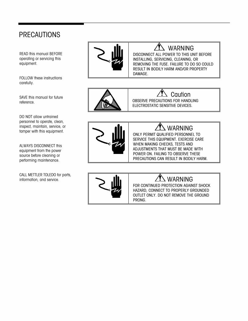
PRECAUTIONS
WARNING DISCONNECT ALL POWER TO THIS UNIT BEFORE INSTALLING, SERVICING, CLEANING, OR REMOVING THE FUSE. FAILURE TO DO SO COULD RESULT IN BODILY HARM AND/OR PROPERTY DAMAGE.
Caution OBSERVE PRECAUTIONS FOR HANDLING ELECTROSTATIC SENSITIVE DEVICES.
WARNING ONLY PERMIT QUALIFIED PERSONNEL TO SERVICE THIS EQUIPMENT. EXERCISE CARE WHEN MAKING CHECKS, TESTS AND ADJUSTMENTS THAT MUST BE MADE WITH POWER ON. FAILING TO OBSERVE THESE PRECAUTIONS CAN RESULT IN BODILY HARM.
WARNING FOR CONTINUED PROTECTION AGAINST SHOCK HAZARD, CONNECT TO PROPERLY GROUNDED OUTLET ONLY. DO NOT REMOVE THE GROUND PRONG.
READ this manual BEFORE operating or servicing this equipment. FOLLOW these instructions carefully. SAVE this manual for future reference. DO NOT allow untrained personnel to operate, clean, inspect, maintain, service, or tamper with this equipment. ALWAYS DISCONNECT this equipment from the power source before cleaning or performing maintenance. CALL METTLER TOLEDO for parts, information, and service.
CONTENTS
1 Introduction .......................................................................................................................1-1 Overview...........................................................................................................................1-1 Product Overview ...............................................................................................................1-1
Panel-Mount Operator Interface (JXOI 0000) – Graphical Display Only.............................1-2 Pedestal Operator Interface (JXOI1000*) – Graphical Display Only ..................................1-2 Harsh Environment Terminal Version (JXHG) ................................................................1-2
Options and Accessories .....................................................................................................1-3 Weighted Base for JXOI Pedestal Version (0917-0311) .................................................1-3 Network Splitter for JXHG (0917-0337) ......................................................................1-3
Product Configuration .........................................................................................................1-4 Specifications ....................................................................................................................1-5 Physical Dimensions ..........................................................................................................1-6
JXOI (Panel-Mount Version) Mounting Dimensions ........................................................1-6 JXOI (Pedestal) Mounting Dimensions .........................................................................1-7 JXHG (Harsh Environment Terminal Version) Mounting Dimensions.................................1-8
JXOI (Pedestal and Panel Versions) Power Considerations ......................................................1-9 JXHG (Harsh Environment Terminal Version) Power Considerations..........................................1-9 JXOI (Pedestal and Panel-Mount) Connections ....................................................................1-10
Serial Port ...............................................................................................................1-10 Power Supply Connection .........................................................................................1-11 Ethernet Port ...........................................................................................................1-11 PS/2 Keyboard Interface ...........................................................................................1-11 JXOI to JAGXTREME Terminal Connections..................................................................1-11
JXHG (Harsh Terminal Version) Connections .......................................................................1-12 Power Supply Connection .........................................................................................1-12 Ethernet Port ...........................................................................................................1-12 PS/2 Keyboard Interface ...........................................................................................1-12 JXHG to JAGXTREME Terminal Connections ................................................................1-12
Components....................................................................................................................1-13 Display...................................................................................................................1-13 Keypad...................................................................................................................1-13 System Memory.......................................................................................................1-13 Software .................................................................................................................1-14
2 JXOI/JXHG Operation ..........................................................................................................2-1 Overview...........................................................................................................................2-1
3 Default Screen Operation .....................................................................................................3-1 Overview...........................................................................................................................3-1 JAGXTREME Terminal Operation ...........................................................................................3-1 Display Setup ....................................................................................................................3-3
Display Setup Menu Items...........................................................................................3-3 JAGXTREME Terminal Selection ............................................................................................3-4 JAGXTREME IP Address Setup ..............................................................................................3-5 Switching to User Application Screen Operation ......................................................................3-5
4 User Application Screen Operation ........................................................................................4-1 Overview...........................................................................................................................4-1
5 Application Development Mode ............................................................................................5-1 Overview...........................................................................................................................5-1 Power On Setup .................................................................................................................5-1
Using an External Keyboard (Pedestal and Panel Versions Only) To Access Power On Setup5-2 Using a Keypad (All Units) to Access Power On Setup ....................................................5-2 Navigation in Power On Setup Using the QWERTY Keyboard ...........................................5-3 Navigation in Power On Setup Using the Keypad ...........................................................5-3
Power On Setup Functions (Menu Items)...............................................................................5-4 Flash Memory ...........................................................................................................5-5 Display.....................................................................................................................5-6 Calibration (Temp).....................................................................................................5-6 Network....................................................................................................................5-6 COM1 ......................................................................................................................5-6 Keypad.....................................................................................................................5-7 Keyboard..................................................................................................................5-7 Miscellaneous ...........................................................................................................5-7 Diagnostics...............................................................................................................5-8 Done........................................................................................................................5-8
6 Service and Maintenance ....................................................................................................6-1 Tools and Supplies.............................................................................................................6-1 Cleaning and Maintenance ..................................................................................................6-1 Troubleshooting .................................................................................................................6-1 Error Codes and Actions......................................................................................................6-2 Diagnostic Tests ................................................................................................................6-2
7 Parts and Accessories ........................................................................................................7-1 JXOI (Panel-Mount Version) ................................................................................................7-1 JXOI (Pedestal Version) ......................................................................................................7-2 JXHG (Harsh Environment Terminal Version) .........................................................................7-3 Accessories and Options .....................................................................................................7-5
Chapter 1: Introduction Overview
(1-03) 1-1
1 Introduction
Overview This manual provides information for setting up and configuring the JAGXTREME operator interface. Separate installation instructions are provided in the JAGXTREME Operator Interface Installation guide that accompanies the unit. Additional resources can be found on the CD-ROM that accompanies the unit.
For additional information, contact your authorized METTLER TOLEDO representative or go to: http://www.mt.com.
Product Overview METTLER TOLEDO's JAGXTREME operator interface (JXOI/JXHG) is an Ethernet-enabled graphical display with object-based programming. Its powerful, flexible, graphics-based system allows customers to quickly and efficiently create user-friendly operator screens tailored to their specific applications.
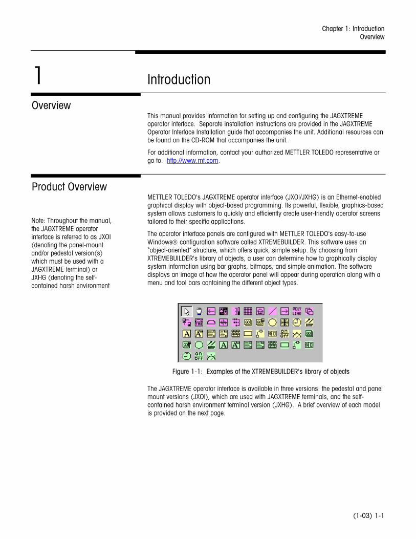
The operator interface panels are configured with METTLER TOLEDO's easy-to-use Windows configuration software called XTREMEBUILDER. This software uses an “object-oriented” structure, which offers quick, simple setup. By choosing from XTREMEBUILDER's library of objects, a user can determine how to graphically display system information using bar graphs, bitmaps, and simple animation. The software displays an image of how the operator panel will appear during operation along with a menu and tool bars containing the different object types.
Figure 1-1: Examples of the XTREMEBUILDER's library of objects
The JAGXTREME operator interface is available in three versions: the pedestal and panel mount versions (JXOI), which are used with JAGXTREME terminals, and the self-contained harsh environment terminal version (JXHG). A brief overview of each model is provided on the next page.
Note: Throughout the manual, the JAGXTREME operator interface is referred to as JXOI (denoting the panel-mount and/or pedestal version(s) which must be used with a JAGXTREME terminal) or JXHG (denoting the self-contained harsh environment
METTLER TOLEDO JAGXTREME Operator Interface Technical Manual
(1-03) 1-2
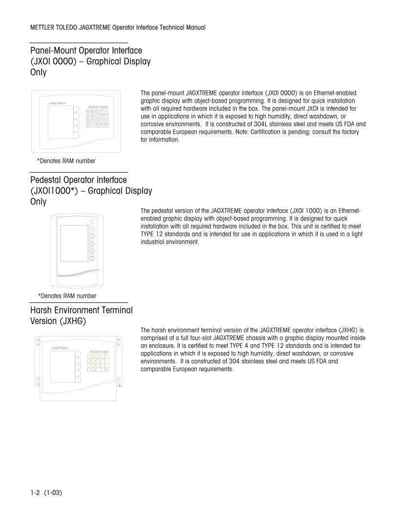
Panel-Mount Operator Interface (JXOI 0000) – Graphical Display Only
The panel-mount JAGXTREME operator interface (JX0I 0000) is an Ethernet-enabled graphic display with object-based programming. It is designed for quick installation with all required hardware included in the box. The panel-mount JXOI is intended for use in applications in which it is exposed to high humidity, direct washdown, or corrosive environments. It is constructed of 304L stainless steel and meets US FDA and comparable European requirements. Note: Certification is pending; consult the factory for information.
*
Pedestal Operator Interface (JXOI1000*) – Graphical Display Only
The pedestal version of the JAGXTREME operator interface (JX0I 1000) is an Ethernet-enabled graphic display with object-based programming. It is designed for quick installation with all required hardware included in the box. This unit is certified to meet TYPE 12 standards and is intended for use in applications in which it is used in a light industrial environment.
Harsh Environment Terminal Version (JXHG)
The harsh environment terminal version of the JAGXTREME operator interface (JXHG) is comprised of a full four-slot JAGXTREME chassis with a graphic display mounted inside an enclosure. It is certified to meet TYPE 4 and TYPE 12 standards and is intended for applications in which it is exposed to high humidity, direct washdown, or corrosive environments. It is constructed of 304 stainless steel and meets US FDA and comparable European requirements.
*Denotes RAM number
*Denotes RAM number
Chapter 1: Introduction Options and Accessories
(1-03) 1-3
Options and Accessories
Weighted Base for JXOI Pedestal Version (0917-0311)
The optional portable weighted base (approximately 8 lbs/3.6 kg) allows for quick mounting of the pedestal JXOI. The weighted base includes a non-slip pad on the bottom for better stability on a desk or tabletop.
Network Splitter for JXHG (0917-0337)
The optional Network Splitter Kit is used to connect the JXHG (harsh environment terminal version) to a 10BASE-T Ethernet network. The cable to the network is NOT provided. The cable must be rated CAT-5 and be no more than 100 feet (30 meters) from the network trunk connection. The cable should be terminated into a network hub or other buffering device.
METTLER TOLEDO JAGXTREME Operator Interface Technical Manual
(1-03) 1-4
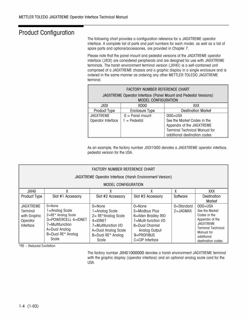
Product Configuration The following chart provides a configuration reference for a JAGXTREME operator interface. A complete list of parts and part numbers for each model, as well as a list of spare parts and options/accessories, are provided in Chapter 7.
Please note that the panel-mount and pedestal versions of the JAGXTREME operator interface (JXOI) are considered peripherals and are designed for use with JAGXTREME terminals. The harsh environment terminal version (JXHG) is a self-contained unit comprised of a JAGXTREME chassis and a graphic display in a single enclosure and is ordered in the same manner as ordering any other METTLER TOLEDO JAGXTREME terminal.
FACTORY NUMBER REFERENCE CHART
JAGXTREME Operator Interface (Panel Mount and Pedestal Versions) MODEL CONFIGURATION
JX0I X000 XXX Product Type Enclosure Type Destination Market
JAGXTREME Operator Interface
0 = Panel mount 1 = Pedestal
000=USA See the Market Codes in the Appendix of the JAGXTREME Terminal Technical Manual for additional destination codes
As an example, the factory number JXOI1000 denotes a JAGXTREME operator interface, pedestal version for the USA.
FACTORY NUMBER REFERENCE CHART
JAGXTREME Operator Interface (Harsh Environment Version)
MODEL CONFIGURATION
JXHG X X X X XXX Product Type Slot #1 Accessory Slot #2 Accessory Slot #3 Accessory Software Destination
Market JAGXTREME Terminal with Graphic Operator Interface
0=None 1=Analog Scale 2=RE* Analog Scale 3=POWERCELL 4=IDNET 7=Multifunction A=Dual Analog B=Dual RE* Analog
Scale
0=None 1=Analog Scale 2= RE*Analog Scale 4=IDNET 7=Multifunction I/O A=Dual Analog Scale B=Dual RE* Analog
Scale
0=None 5=Modbus Plus 6=Allen Bradley RIO 7=Multi-function I/O 8=Dual Channel
Analog Output 9=PROFIBUS C=CIP Interface
0=Standard 2=JAGMAX
000=USA See the Market Codes in the Appendix of the JAGXTREME Terminal Technical Manual for additional destination codes
*RE – Reduced Excitation
The factory number JXHG1000000 denotes a harsh environment JAGXTREME terminal with the graphic display (operator interface) and an optional analog scale card for the USA.
Chapter 1: Introduction Specifications
(1-03) 1-5
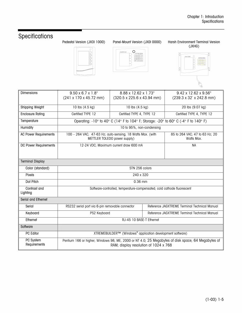
Specifications Pedestal Version (JXOI 1000)
Panel-Mount Version (JX0I 0000)
Harsh Environment Terminal Version (JXHG)
Dimensions 9.50 x 6.7 x 1.8" (241 x 170 x 45.72 mm)
8.88 x 12.62 x 1.73" (320.5 x 225.6 x 43.94 mm)
9.42 x 12.62 x 9.56" (239.3 x 32` x 242.8 mm)
Shipping Weight 10 lbs (4.5 kg) 10 lbs (4.5 kg) 20 lbs (9.07 kg)
Enclosure Rating Certified TYPE 12 Certified TYPE 4, TYPE 12 Certified TYPE 4, TYPE 12
Temperature Operating: -10° to 40° C (14° F to 104° F; Storage: -20° to 60° C (-4° F to 140° F)
Humidity 10 to 95%, non-condensing
AC Power Requirements 100 – 264 VAC; 47-63 Hz; auto-sensing; 18 Watts Max. (with METTLER TOLEDO power supply)
85 to 264 VAC; 47 to 63 Hz; 20 Watts Max.
DC Power Requirements 12-24 VDC; Maximum current draw 600 mA NA
Terminal Display
Color (standard) STN 256 colors
Pixels 240 x 320
Dot Pitch 0.36 mm
Contrast and Lighting
Software-controlled, temperature-compensated; cold cathode fluorescent
Serial and Ethernet
Serial RS232 serial port via 6-pin removable connector Reference JAGXTREME Terminal Technical Manual
Keyboard PS2 Keyboard Reference JAGXTREME Terminal Technical Manual
Ethernet RJ-45 10 BASE-T Ethernet
Software
PC Editor XTREMEBUILDER™ (Windows® application development software)
PC System Requirements
Pentium 166 or higher; Windows 98, ME, 2000 or NT 4.0; 25 Megabytes of disk space; 64 Megabytes of RAM; display resolution of 1024 x 768
METTLER TOLEDO JAGXTREME Operator Interface Technical Manual
(1-03) 1-6
Physical Dimensions
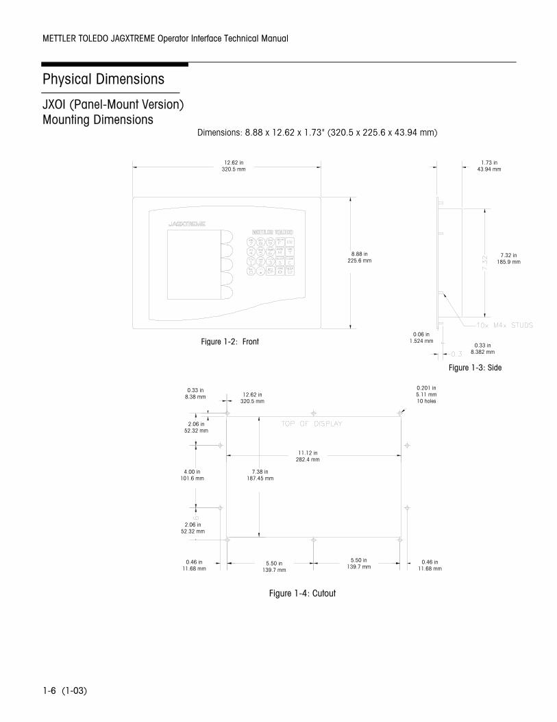
JXOI (Panel-Mount Version) Mounting Dimensions
Dimensions: 8.88 x 12.62 x 1.73" (320.5 x 225.6 x 43.94 mm)
12.62 in 320.5 mm
8.88 in 225.6 mm
1.73 in 43.94 mm
7.32 in 185.9 mm
0.06 in 1.524 mm
0.33 in 8.382 mm
4.00 in 101.6 mm
2.06 in 52.32 mm
0.46 in 11.68 mm
5.50 in 139.7 mm
5.50 in 139.7 mm
0.46 in 11.68 mm
7.38 in 187.45 mm
0.33 in 8.38 mm
11.12 in 282.4 mm
2.06 in 52.32 mm
12.62 in 320.5 mm
0.201 in 5.11 mm 10 holes
Figure 1-2: Front
Figure 1-3: Side
Figure 1-4: Cutout
Chapter 1: Introduction Physical Dimensions
(1-03) 1-7
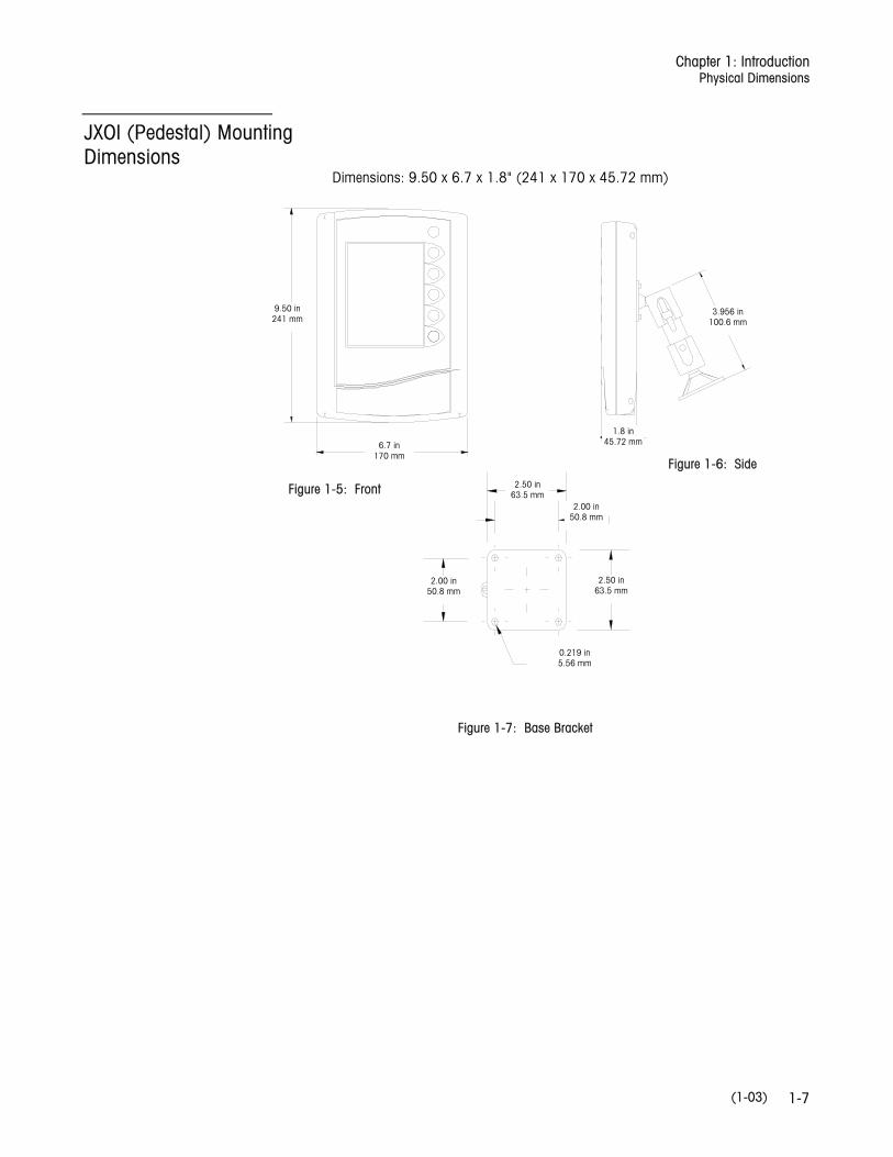
JXOI (Pedestal) Mounting Dimensions
Dimensions: 9.50 x 6.7 x 1.8" (241 x 170 x 45.72 mm)
9.50 in 241 mm
6.7 in 170 mm
3.956 in 100.6 mm
1.8 in 45.72 mm
2.50 in 63.5 mm
2.50 in 63.5 mm
2.00 in 50.8 mm
2.00 in 50.8 mm
0.219 in 5.56 mm
Figure 1-5: Front
Figure 1-6: Side
Figure 1-7: Base Bracket
METTLER TOLEDO JAGXTREME Operator Interface Technical Manual
(1-03) 1-8
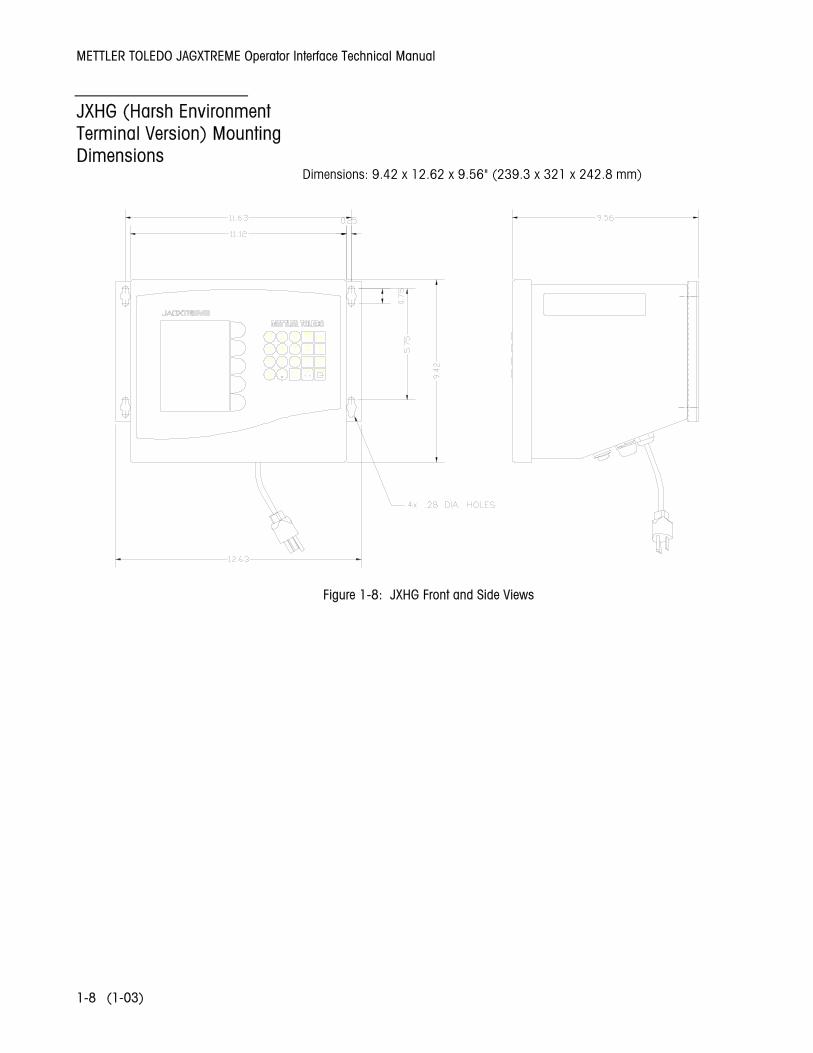
JXHG (Harsh Environment Terminal Version) Mounting Dimensions
Dimensions: 9.42 x 12.62 x 9.56" (239.3 x 321 x 242.8 mm)
Figure 1-8: JXHG Front and Side Views
Chapter 1: Introduction JXOI (Pedestal and Panel Versions) Power Considerations
(1-03) 1-9
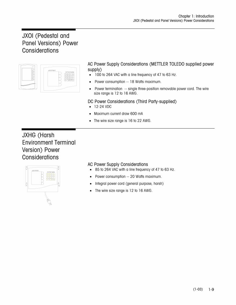
JXOI (Pedestal and Panel Versions) Power Considerations
AC Power Supply Considerations (METTLER TOLEDO supplied power supply) • 100 to 264 VAC with a line frequency of 47 to 63 Hz.
• Power consumption -- 18 Watts maximum.
• Power termination -- single three-position removable power cord. The wire size range is 12 to 16 AWG.
DC Power Considerations (Third Party-supplied) • 12-24 VDC
• Maximum current draw 600 mA
• The wire size range is 16 to 22 AWG.
JXHG (Harsh Environment Terminal Version) Power Considerations
AC Power Supply Considerations • 85 to 264 VAC with a line frequency of 47 to 63 Hz.
• Power consumption -- 20 Watts maximum.
• Integral power cord (general purpose, harsh)
• The wire size range is 12 to 16 AWG.
METTLER TOLEDO JAGXTREME Operator Interface Technical Manual
(1-03) 1-10
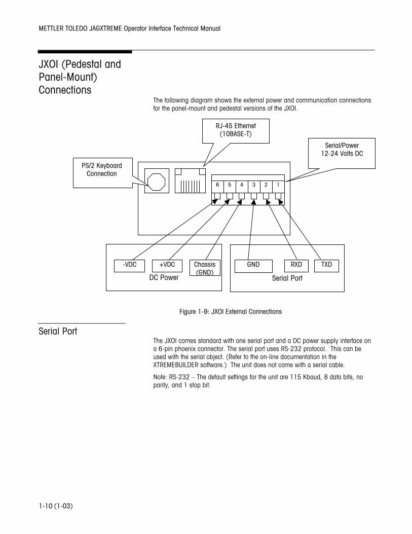
JXOI (Pedestal and Panel-Mount) Connections
The following diagram shows the external power and communication connections for the panel-mount and pedestal versions of the JXOI.
Serial Port The JXOI comes standard with one serial port and a DC power supply interface on a 6-pin phoenix connector. The serial port uses RS-232 protocol. This can be used with the serial object. (Refer to the on-line documentation in the XTREMEBUILDER software.) The unit does not come with a serial cable.
Note: RS-232 – The default settings for the unit are 115 Kbaud, 8 data bits, no parity, and 1 stop bit.
P
Serial Port
DC Power
RJ-45 Ethernet (10BASE-T)
Serial/Power 12-24 Volts DC
-VDC +VDC Chassis (GND)
GND RXD TXD
6 5 4 3 2 1
PS/2 Keyboard Connection
Figure 1-9: JXOI External Connections
Chapter 1: Introduction JXOI (Pedestal and Panel-Mount) Connections
(1-03) 1-11
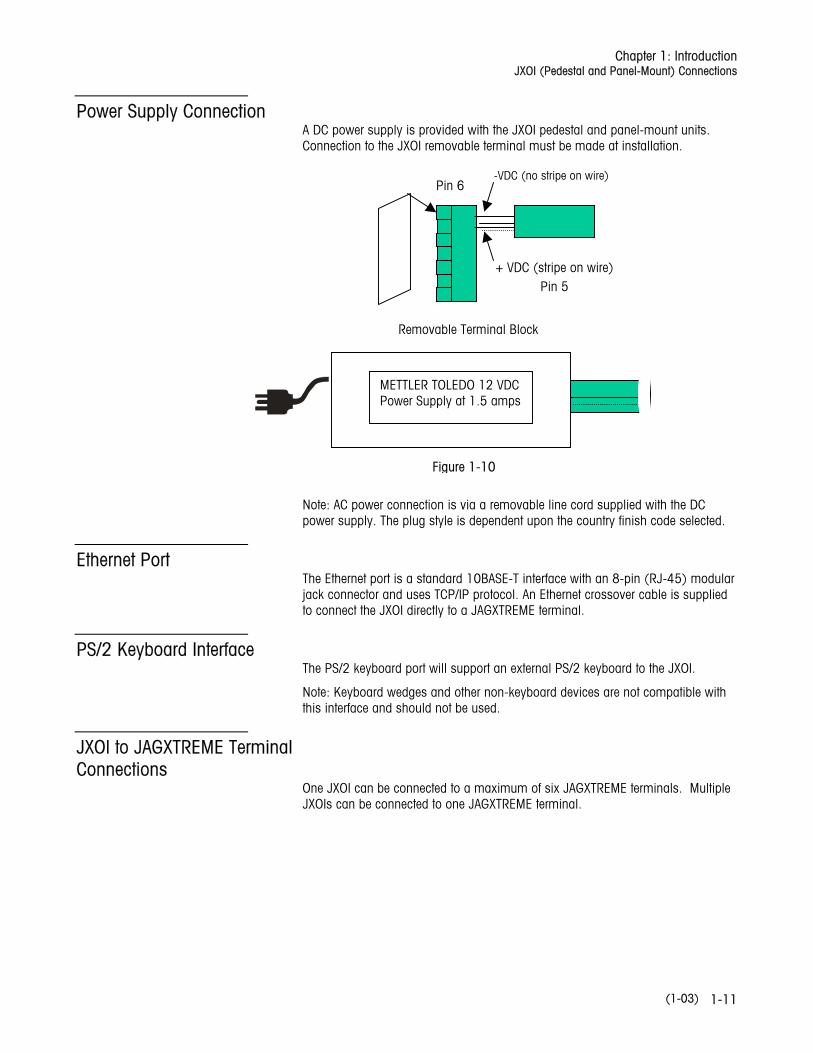
Power Supply Connection A DC power supply is provided with the JXOI pedestal and panel-mount units. Connection to the JXOI removable terminal must be made at installation.
Note: AC power connection is via a removable line cord supplied with the DC power supply. The plug style is dependent upon the country finish code selected.
Ethernet Port The Ethernet port is a standard 10BASE-T interface with an 8-pin (RJ-45) modular jack connector and uses TCP/IP protocol. An Ethernet crossover cable is supplied to connect the JXOI directly to a JAGXTREME terminal.
PS/2 Keyboard Interface The PS/2 keyboard port will support an external PS/2 keyboard to the JXOI.
Note: Keyboard wedges and other non-keyboard devices are not compatible with this interface and should not be used.
JXOI to JAGXTREME Terminal Connections
One JXOI can be connected to a maximum of six JAGXTREME terminals. Multiple JXOIs can be connected to one JAGXTREME terminal.
+ VDC (stripe on wire)
Pin 5
-VDC (no stripe on wire) Pin 6
Removable Terminal Block
METTLER TOLEDO 12 VDC Power Supply at 1.5 amps
Figure 1-10
METTLER TOLEDO JAGXTREME Operator Interface Technical Manual
(1-03) 1-12
JXHG (Harsh Terminal Version) Connections
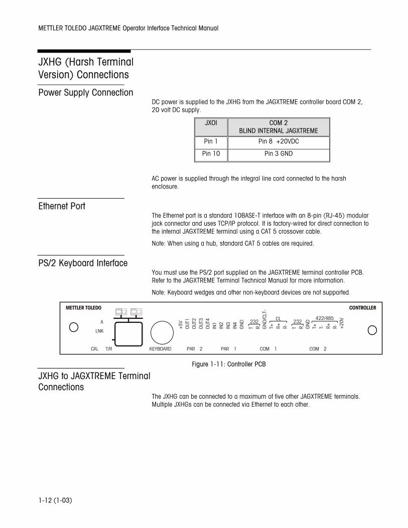
Power Supply Connection DC power is supplied to the JXHG from the JAGXTREME controller board COM 2, 20 volt DC supply.
JXOI COM 2 BLIND INTERNAL JAGXTREME
Pin 1 Pin 8 +20VDC
Pin 10 Pin 3 GND
AC power is supplied through the integral line cord connected to the harsh enclosure.
Ethernet Port The Ethernet port is a standard 10BASE-T interface with an 8-pin (RJ-45) modular jack connector and uses TCP/IP protocol. It is factory-wired for direct connection to the internal JAGXTREME terminal using a CAT 5 crossover cable.
Note: When using a hub, standard CAT 5 cables are required.
PS/2 Keyboard Interface You must use the PS/2 port supplied on the JAGXTREME terminal controller PCB. Refer to the JAGXTREME Terminal Technical Manual for more information.
Note: Keyboard wedges and other non-keyboard devices are not supported.
JXHG to JAGXTREME Terminal Connections
The JXHG can be connected to a maximum of five other JAGXTREME terminals. Multiple JXHGs can be connected via Ethernet to each other.
LNK
T/R
METTLER TOLEDO
A
KEYBOARD PAR 2 PAR 1 COM 1 COM 2
CONTROLLER
422/485232CL232
+5V
OUT
1O
UT2
OUT
3O
UT4
IN1
IN2
IN3
IN4
GN
D
T R T+ R+ R- T R T+ T- R+ R-GN
D
+20
V
GN
D/C
LT-
Figure 1-11: Controller PCB
Chapter 1: Introduction Components
(1-03) 1-13
Components
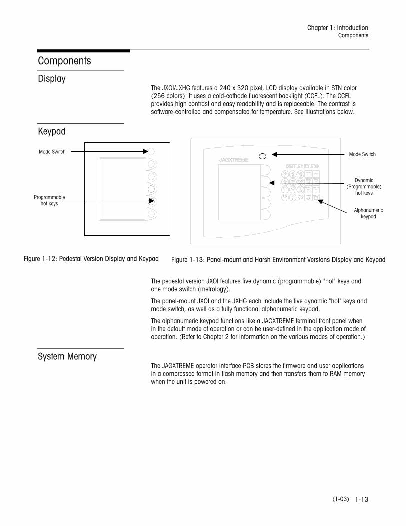
Display The JXOI/JXHG features a 240 x 320 pixel, LCD display available in STN color (256 colors). It uses a cold-cathode fluorescent backlight (CCFL). The CCFL provides high contrast and easy readability and is replaceable. The contrast is software-controlled and compensated for temperature. See illustrations below.
Keypad
The pedestal version JXOI features five dynamic (programmable) "hot" keys and one mode switch (metrology).
The panel-mount JXOI and the JXHG each include the five dynamic "hot" keys and mode switch, as well as a fully functional alphanumeric keypad.
The alphanumeric keypad functions like a JAGXTREME terminal front panel when in the default mode of operation or can be user-defined in the application mode of operation. (Refer to Chapter 2 for information on the various modes of operation.)
System Memory The JAGXTREME operator interface PCB stores the firmware and user applications in a compressed format in flash memory and then transfers them to RAM memory when the unit is powered on.
Figure 1-12: Pedestal Version Display and Keypad Figure 1-13: Panel-mount and Harsh Environment Versions Display and Keypad
Mode Switch
Programmable hot keys
Mode Switch
Dynamic (Programmable)
hot keys
Alphanumeric keypad
METTLER TOLEDO JAGXTREME Operator Interface Technical Manual
(1-03) 1-14
Software JAGXTREME Operator Interface Operating System The operating system comes factory-loaded into every unit. It contains the boot code, system configuration, and the default screens.
XTREMEBUILDER Object Library The XTREMEBUILDER Object Library is supplied with the XTREMEBUILDER Editor and is used to create user-defined application screens. The objects are configured using the XTREMEBUILDER WYSIWYG screen editor and then compiled and downloaded into the operator interface PCB.
XTREMEBUILDER CODE The XTREMEBUILDER Code is standard in every unit. XTREMEBUILDER Code is a tool for customizing objects. The XTREMEBUILDER Editor provides a "code view" function that enables programmers to modify or create their own objects using XTREMEBUILDER Code.
Chapter 2: JXOI/JXHG Operation Overview
(1-03) 2-1
2 JXOI/JXHG Operation
Overview The JXOI/JXHG has three possible screen operations: Default Screen operation, User Application Screen operation, and Application Development mode.
Default Screen Operation. Default Screen operation is used to emulate the front panel of a JAGXTREME terminal. Default Screen operation allows the user to simultaneously view all scale platforms and the logical sum of those platforms. Default Screen operation has been approved for legal-for-trade operations. Detailed information for using Default Screen operation is provided in Chapter 3 of this manual.
User Application Screen Operation. User Application Screen operation is optional and requires configuration using the XTREMEBUILDER Editor and object library. The application screens are intended to enable the user to create intuitive visual displays of the scale and associated processes. Detailed information for using User Application Screen operation is provided in Chapter 4 of this manual.
Application Development Mode. Application Development mode is similar to Application Screen operation except the screen configurations are not permanently stored. This mode of operation is used for configuring user application screens. It enables the programmer to easily modify screens and works in unison with the XTREMEBUILDER Editor. Detailed information on using Application Development mode is provided in Chapter 5 of this manual.
Upon applying power to the JXOI/JXHG, the unit will initiate communication with the connected JAGXTREME terminal(s). If the JXOI/JXHG cannot establish communication with the connected JAGXTREME terminal(s), an error message will be displayed on the front of the display indicating a communication failure.
It will then check the "power on setup" configuration file stored inside its memory to determine which screen operation is active (Default Screen operation or User Application Screen operation).
Note: For installation instructions, refer to the JAGXTREME Operator Interface Installation Guide or the documentation CD-ROM that ships with the unit from the factory.

METTLER TOLEDO JAGXTREME Operator Interface Technical Manual
(1-03) 2-2
NOTES
Chapter 3: Default Screen Operation Overview
(1-03) 3-1
3 Default Screen Operation
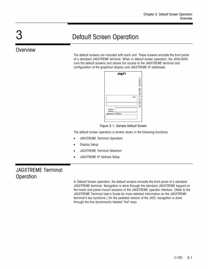
Overview The default screens are included with each unit. These screens emulate the front panel of a standard JAGXTREME terminal. When in default screen operation, the JXOI/JXHG runs the default screens and allows full access to the JAGXTREME terminal and configuration of the graphical display and JAGXTREME IP addresses.
The default screen operation is broken down in the following functions:
• JAGXTREME Terminal Operation
• Display Setup
• JAGXTREME Terminal Selection
• JAGXTREME IP Address Setup
JAGXTREME Terminal Operation
In Default Screen operation, the default screens emulate the front panel of a standard JAGXTREME terminal. Navigation is done through the standard JAGXTREME keypad on the harsh and panel-mount versions of the JAGXTREME operator interface. (Refer to the JAGXTREME Terminal User's Guide for more detailed information on the JAGXTREME terminal's key functions.) On the pedestal version of the JXOI, navigation is done through the five dynamically labeled "hot" keys.
Figure 3-1: Sample Default Screen
METTLER TOLEDO JAGXTREME Operator Interface Technical Manual
(1-03) 3-2
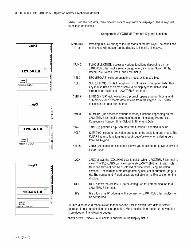
When using the hot keys, three different sets of keys may be displayed. These keys are be defined as follows:
Comparable JAGXTREME Terminal Key and Function
More Key
(…) Pressing this key changes the functions of the hot keys. The definitions of the keys will appear on the display to the left of the keys.
*FUNC FUNC (FUNCTION) accesses various functions depending on the JAGXTREME terminal’s setup configuration, including Switch Units, Recall Tare, Recall Gross, and Enter Setup.
*ESC ESC (ESCAPE) exits an operating mode, exits a sub-bloc
*SEL SEL (SELECT) scrolls through and displays items in option lists. This key is also used to select a scale to be displayed for networked terminals or multi-scale JAGXTREME terminals.
*ENTR ENTR (ENTER) acknowledges a prompt, opens program blocks and sub-blocks, and accepts data entered from the keypad. ENTR also initiates a demand print output.
*MEM MEMORY (M) accesses various memory functions depending on the
JAGXTREME terminal’s setup configuration, including Prompt List, Consecutive Number, Enter Setpoint, Time, and Date.
*TARE TARE (T) performs a pushbutton tare function if enabled in setup.
*CLR CLEAR (C) clears a tare value and returns the scale to gross mode. The CLEAR key also functions as a backspace/delete when entering data from the keypad.
*ZERO ZERO (0) zeroes the scale and allows you to exit to the previous level in setup mode.
JAGX JAGX allows the JXOI/JXHG user to select which JAGXTREME terminal to
view. The JXOI/JXHG can view up to six JAGXTREME terminals. Note: Only one terminal can be displayed at once while using the default screens. The terminals are designated by sequential numbers (JagX 1-6). The names and IP addresses are editable in the IP's section on the display.
DISP DISP allows the JXOI/JXHG to be configured for communication to a JAGXTREME terminal.
IPs IPs allows the IP address of the connection JAGXTREME terminal(s) to be configured.
All units also have a mode switch that allows the user to switch from default screen operation to user application screen operation. More detailed information on navigation is provided on the following pages.
*Keys active if "Show JAGX Keys" is enabled in the Display Setup.
Chapter 3: Default Screen Operation Display Setup
(1-03) 3-3
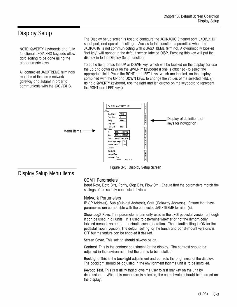
Display Setup The Display Setup screen is used to configure the JXOI/JXHG Ethernet port, JXOI/JXHG serial port, and operation settings. Access to this function is permitted when the JXOI/JXHG is not communicating with a JAGXTREME terminal. A dynamically labeled "hot key" will appear in the default screen labeled DISP. Pressing this key will put the display in to the Display Setup function.
To edit a field, press the UP or DOWN key, which will be labeled on the display (or use the up and down keys on the QWERTY keyboard if one is attached) to select the appropriate field. Press the RGHT and LEFT keys, which are labeled, on the display, combined with the UP and DOWN keys, to change the values of the selected field. (If using a QWERTY keyboard, use the right and left arrows on the keyboard to represent the RGHT and LEFT keys).
Display Setup Menu Items COM1 Parameters Baud Rate, Data Bits, Parity, Stop Bits, Flow Ctrl. Ensure that the parameters match the settings of the serially connected devices.
Network Parameters IP (IP Address), Sub (Sub-net Address), Gate (Gateway Address). Ensure that these parameters are compatible with the connected JAGXTREME terminal(s).
Show JagX Keys. This parameter is primarily used in the JXOI pedestal version although it can be used in all units. It is used to determine whether or not the dynamically labeled menu keys are on in default screen operation. The default setting is ON for the pedestal mount version. The default setting for the harsh and panel-mount versions is OFF but the feature can be enabled if desired.
Screen Saver. This setting should always be off.
Contrast. This is the contrast adjustment for the display. The contrast should be adjusted in the environment that the unit is to be installed.
Backlight. This is the backlight adjustment and controls the brightness of the display. The backlight should be adjusted in the environment that the unit is to be installed.
Keypad Test. This is a utility that allows the user to test any key on the unit by depressing it. When this menu item is selected, the correct value should be returned on the display.
Figure 3-5: Display Setup Screen
Display of definitions of keys for navigation
Menu items
NOTE: QWERTY keyboards and fully functional JXOI/JXHG keypads allow data editing to be done using the alphanumeric keys. All connected JAGXTREME terminals must be at the same network gateway and subnet in order to communicate with the JXOI/JXHG.
METTLER TOLEDO JAGXTREME Operator Interface Technical Manual
(1-03) 3-4
Keyboard Test. This is a utility that allows the user to troubleshoot QWERTY keyboard problems. When any key is depressed that key should be displayed. Pressing the ENTER key exits testing.
Done. This acts as a Save and Exit function.
Abort. This allows the user to escape setup without making changes.
JAGXTREME Terminal Selection
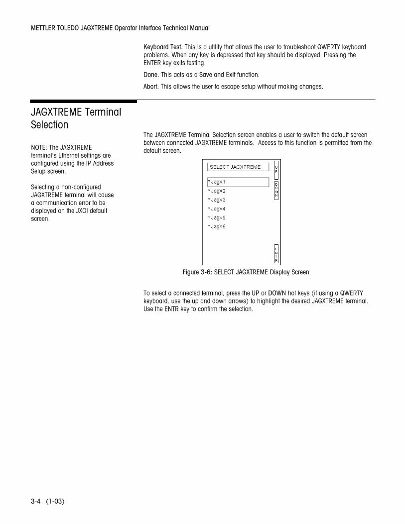
The JAGXTREME Terminal Selection screen enables a user to switch the default screen between connected JAGXTREME terminals. Access to this function is permitted from the default screen.
To select a connected terminal, press the UP or DOWN hot keys (if using a QWERTY keyboard, use the up and down arrows) to highlight the desired JAGXTREME terminal. Use the ENTR key to confirm the selection.
Figure 3-6: SELECT JAGXTREME Display Screen
NOTE: The JAGXTREME terminal's Ethernet settings are configured using the IP Address Setup screen. Selecting a non-configured JAGXTREME terminal will cause a communication error to be displayed on the JXOI default screen.
Chapter 3: Default Screen Operation JAGXTREME IP Address Setup
(1-03) 3-5
JAGXTREME IP Address Setup
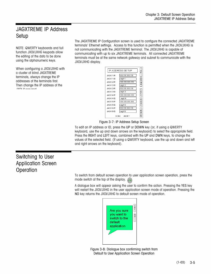
The JAGXTREME IP Configuration screen is used to configure the connected JAGXTREME terminals’ Ethernet settings. Access to this function is permitted when the JXOI/JXHG is not communicating with the JAGXTREME terminal. The JXOI/JXHG is capable of communicating with up to six JAGXTREME terminals. All connected JAGXTREME terminals must be at the same network gateway and subnet to communicate with the JXOI/JXHG display.
To edit an IP address or ID, press the UP or DOWN key (or, if using a QWERTY keyboard, use the up and down arrows on the keyboard) to select the appropriate field. Press the RGHT and LEFT keys, combined with the UP and DWN keys, to change the values of the selected field. (If using a QWERTY keyboard, use the up and down and left and right arrows on the keyboard).
Switching to User Application Screen Operation
To switch from default screen operation to user application screen operation, press the mode switch at the top of the display.
A dialogue box will appear asking the user to confirm the action. Pressing the YES key will restart the JXOI/JXHG in the user application screen mode of operation. Pressing the NO key returns the JXOI/JXHG to default screen mode of operation.
Figure 3-7: IP Address Setup Screen
Figure 3-8: Dialogue box confirming switch from Default to User Application Screen Operation
NOTE: QWERTY keyboards and full function JXOI/JXHG keypads allow the editing of the data to be done using the alphanumeric keys. When configuring a JXOI/JXHG with a cluster of blind JAGXTREME terminals, always change the IP addresses of the terminals first. Then change the IP address of the JXOI if required

METTLER TOLEDO JAGXTREME Operator Interface Technical Manual
(1-03) 3-6
NOTES
Chapter 4: User Application Screen Operation Overview
(1-03) 4-1
4 User Application Screen Operation
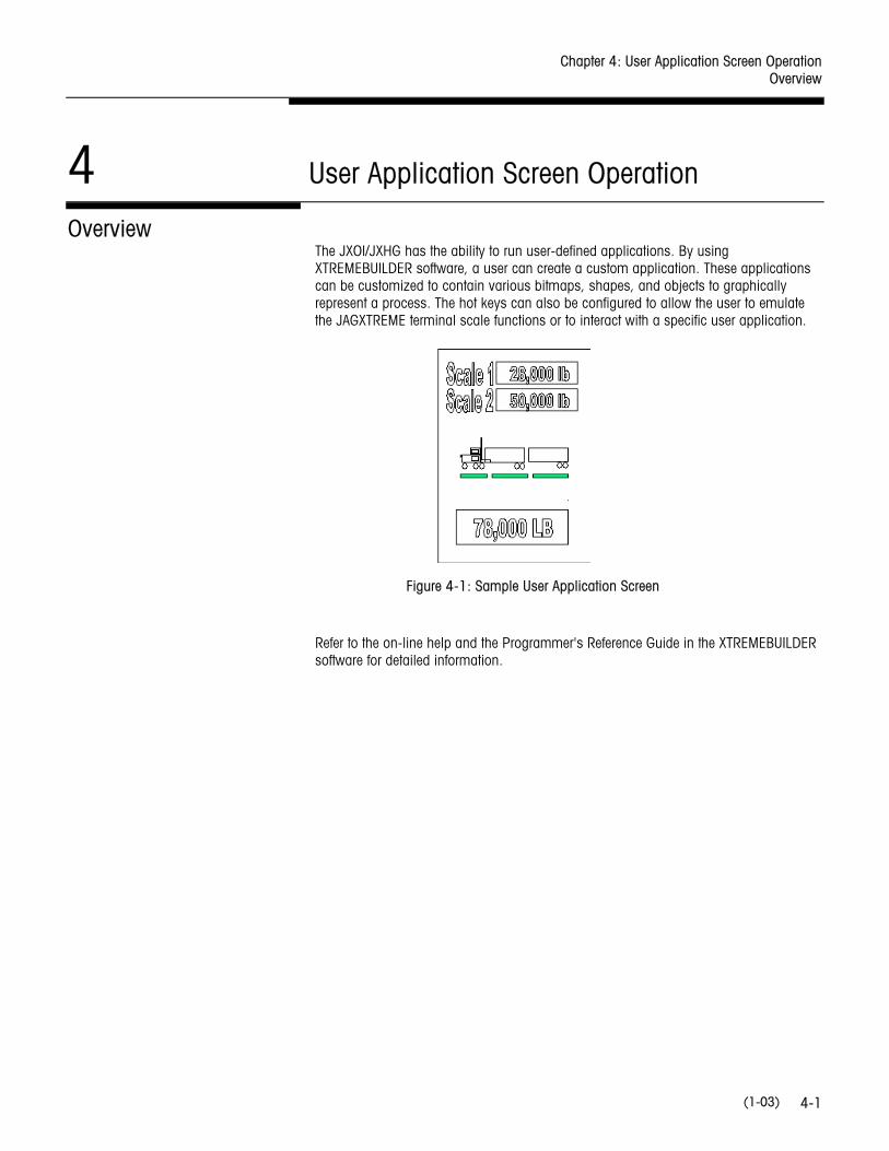
Overview The JXOI/JXHG has the ability to run user-defined applications. By using XTREMEBUILDER software, a user can create a custom application. These applications can be customized to contain various bitmaps, shapes, and objects to graphically represent a process. The hot keys can also be configured to allow the user to emulate the JAGXTREME terminal scale functions or to interact with a specific user application.
Refer to the on-line help and the Programmer's Reference Guide in the XTREMEBUILDER software for detailed information.
Figure 4-1: Sample User Application Screen

METTLER TOLEDO JAGXTREME Operator Interface Technical Manual
(1-03) 4-2
NOTES

Chapter 5: Application Development Mode Overview
(1-03) 5-1
5 Application Development Mode
Overview Application Development mode is used to create user application screens. Application Development mode requires a JXOI/JXHG, a PC with the XTREMEBUILDER Editor and object library, and an Ethernet interface cable.
To develop a user application, the JXOI/JXHG must be configured for Application Development mode through the "Power On Setup" utility.
Power On Setup The Power On Setup utility is used to set up or change the JXOI/JXHG operation settings. This mode of operation should not be confused with the default screens or the user application screens.
The Power On Setup utility is accessed by:
• Holding down any three "hot" keys on the JXOI/JXHG front panel during power-up.
• With an external QWERTY keyboard, holding down the "P" key (not case-sensitive) during power-up.
Power On Setup includes functions to do the following:
• Download new firmware.
• Download user applications.
• Select the application mode (default, user application, application development).
• Set communications settings (also can be done via the default screens).
• Adjust display settings -- contrast, backlight, orientation (also can be done via the default screens).
• Enter network (Ethernet) settings (can also be done via the default screens).
• Enter/change password (if used).
METTLER TOLEDO JAGXTREME Operator Interface Technical Manual
(1-03) 5-2
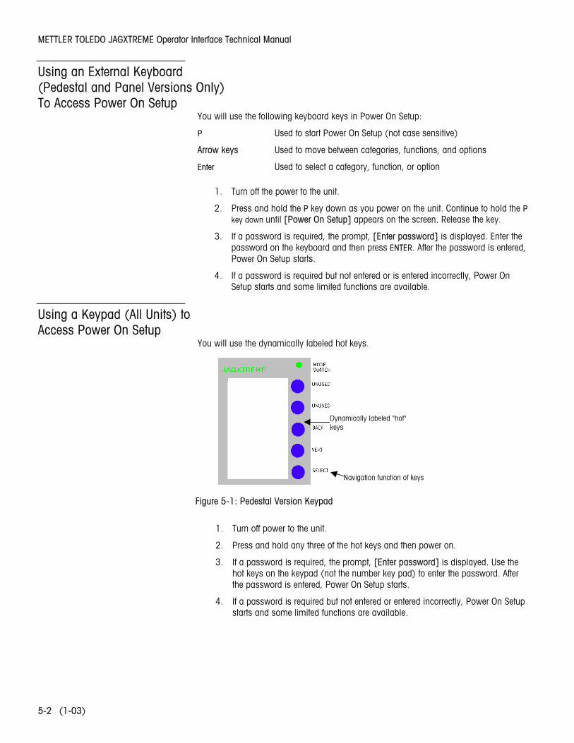
Using an External Keyboard (Pedestal and Panel Versions Only) To Access Power On Setup
You will use the following keyboard keys in Power On Setup:
P Used to start Power On Setup (not case sensitive)
Arrow keys Used to move between categories, functions, and options
Enter Used to select a category, function, or option
1. Turn off the power to the unit.
2. Press and hold the P key down as you power on the unit. Continue to hold the P key down until [Power On Setup] appears on the screen. Release the key.
3. If a password is required, the prompt, [Enter password] is displayed. Enter the password on the keyboard and then press ENTER. After the password is entered, Power On Setup starts.
4. If a password is required but not entered or is entered incorrectly, Power On Setup starts and some limited functions are available.
Using a Keypad (All Units) to Access Power On Setup
You will use the dynamically labeled hot keys.
1. Turn off power to the unit.
2. Press and hold any three of the hot keys and then power on.
3. If a password is required, the prompt, [Enter password] is displayed. Use the hot keys on the keypad (not the number key pad) to enter the password. After the password is entered, Power On Setup starts.
4. If a password is required but not entered or entered incorrectly, Power On Setup starts and some limited functions are available.
Pedestal Version Keypad
ProgramKeys
Nafunkey
Dynamically labeled "hot" keys
Navigation function of keys
Figure 5-1: Pedestal Version Keypad

Chapter 5: Application Development Mode Power On Setup
(1-03) 5-3
Navigation in Power On Setup Using the QWERTY Keyboard
To move from category to category:
Press the arrow keys to move forward or backwards from one category of functions (e.g., Flash Memory, Display, Calibration, etc.) to another. A heading is highlighted when you move to it. Continue to press the arrow key to move to the next page.
To move within a category:
When the category heading you want to edit is highlighted, press ENTER to move to the first function. Press the arrow keys to move from function to function in the category. To go back to the category heading, go to the topmost function and press the appropriate arrow key or go to the bottommost function. Press the arrow keys to move from category to category again.
To change a function:
When at a function that you want to edit, press ENTER to move to the available options. Press the arrow keys to toggle through the options. When the option you want is displayed, press ENTER to select the option and move back to the function name.
Saving and Exiting:
When you are ready to exit Power On Setup, press either arrow key (with a category heading highlighted) to move to DONE on the last page, and press ENTER. Save and Exit is highlighted. Press ENTER to save your changes and exit Power On Setup. To exit without saving the changes, press to move to Exit w/o Save and then press ENTER.
Navigation in Power On Setup Using the Keypad
To move from category to category:
Press BACK or NEXT to move forward or backwards from one category of functions (e.g., Flash Memory, Display, Calibration, etc.) to another. A heading is highlighted when you move to it. Continue to press BACK or NEXT to move between pages.
To move within a category:
When the category heading you want to edit is highlighted, press SELECT to move to the first function. Press BACK or NEXT to move between functions in the category. To go back to the category heading, go to the topmost function and press BACK or go to the bottommost function. Press BACK or NEXT to move from category to category again.
To change a function:
When at a function that you want to edit, press SELECT to move to the available options. Press BACK or NEXT to toggle through the options. When the option you want is displayed, press SELECT to select the option and move back to the function name.
Saving and Exiting:
When you are ready to exit Power On Setup, press BACK or NEXT (with a category heading highlighted) to move to DONE on the last page, and press SELECT. Save and Exit is highlighted. Press SELECT to save your changes and exit Power On Setup. To exit without saving the changes, press BACK or NEXT to move to Exit w/o Save and then press SELECT.
METTLER TOLEDO JAGXTREME Operator Interface Technical Manual
(1-03) 5-4
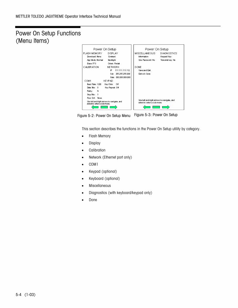
Power On Setup Functions (Menu Items)
This section describes the functions in the Power On Setup utility by category.
• Flash Memory
• Display
• Calibration
• Network (Ethernet port only)
• COM1
• Keypad (optional)
• Keyboard (optional)
• Miscellaneous
• Diagnostics (with keyboard/keypad only)
• Done
Figure 5-2: Power On Setup Menu Figure 5-3: Power On Setup

Chapter 5: Application Development Mode Power On Setup Functions (Menu Items)
(1-03) 5-5
Flash Memory The Flash Memory functions are used to place the unit in the proper mode to download new firmware or a user application, place the unit in the proper mode for developing a new user application or normal operation, and erase the flash file system.
Download Use this function to place the unit in the proper mode to download new firmware or a user application. Possible selections are as follows:
Firmware
Select this option to place the unit in the mode to receive new firmware (system software) through a serial port. The primary serial port is used.
App (/FW)
Select this option to place a unit with either a serial port or Ethernet port in the mode to download a new user application that you want saved in flash memory. (Use “App Mode: Develop” if you do not want to save the user application to flash memory.) You should also select this option to place a unit with the Ethernet port in the mode to receive new firmware (system software). If downloading through an Ethernet port, the unit waits for the download and detects the type of file (firmware or user application) as it is sent.
NOTE:Verify Ethernet network settings.
None
App Mode Use this function to place the unit in the proper mode for developing a new user application or for normal operation.
Default (Default Screen mode)
Refer to Chapter 3 of this manual for information.
Normal
Select this option to set the unit to “normal” operation mode. If the unit is in normal mode and a user application was saved in flash memory, the application runs when the unit is powered on.
Develop
Select this option to set the unit to the “development” application mode, normally only used when you are developing a new user application and want to download it to the unit without saving it in flash memory.
While the unit is in develop mode, a user application downloaded to the unit is not saved in flash memory. This saves unnecessary wear on the flash memory and speeds up download time while testing an application in development. However, the application is removed when the unit is powered off.
If you previously downloaded an application using the “Download: App (/FW)” function that application remains in flash memory (it is not overwritten by an application downloaded while in develop mode). This makes it possible to test a new application without copying over an existing application.
Erase FFS Use this function to erase the flash file system. The flash file system is used to store user application screens.
METTLER TOLEDO JAGXTREME Operator Interface Technical Manual
(1-03) 5-6
Display These functions are used to adjust the display’s contrast setting, the brightness of its backlighting, and to change its orientation (portrait or landscape).
Contrast Use this function to adjust the contrast setting of the unit display.
Backlight Use this function to adjust the brightness of the display.
Orient Use this function to change the orientation of the display to match its physical orientation. If the unit is turned so that the longest dimension is vertical, select Portrait; if the longest dimension is horizontal, select Landscape.
Decache Use this function to speed up a user application.
Calibration (Temp) A default temperature is set at the factory. If there is more than a 5° Celsius difference between the default temperature shown and the surrounding air temperature, you may want to change this setting. This parameter is used to help with display contrast compensation.
Network Use this function to enter network addresses for the Ethernet port. If you do not know the network addresses, consult your network administrator. This section edits the:
• IP address • Subnet mask • Gateway
NOTE: The default IP address of every JAGXTREME terminal is 111.111.111.111. The default IP address of every JXOI/JXHG is 111.111.111.110. The default subnet mask of every JAGXTEME terminal and of every JXOI/JXHG is 255.255.255.0. The default gateway address of every JAGXTREME terminal is 000.000.000.000. The default gateway address of the JXOI and of the JXHG (display portion) is 000.000.000.001.
COM1 Baud Rate: Select the baud rate (600 – 115,200 bps).
Data Bits: Select the number of data bits: 7 or 8.
Parity: Select the parity setting: N (none), O (odd), or E (even).
Stop Bits: Select the number of stop bits: 1 or 2.
Flow Ctrl: Set to None.
Chapter 5: Application Development Mode Power On Setup Functions (Menu Items)
(1-03) 5-7
Keypad You will only see this category if your unit is set up to use a keypad.
Key Click Not supported.
Key Repeat Use this function to turn the key repeat feature on or off. If “on,” a key entry repeats if you hold down the key on the keypad.
Rpt Delay
You will only see this function if you selected On at the Key Repeat field (see section above). Use this function to select the delay time that you want between when a key is pressed and when it begins to repeat automatically.
Rpt Rate
You will only see this function if you selected On at the Key Repeat field. Use this function to select the time that you want between each repeat when a key begins to repeat automatically.
Keyboard You will only see this category if you have a keyboard connected to the JXOI/JXHG.
Rpt Delay Use this function to select the delay time that you want between when a key is pressed and when it begins to repeat automatically.
Rpt Rate Use this function to select the time that you want between each repeat when a key begins to repeat automatically.
Miscellaneous The Miscellaneous functions are used to set up a password for Power On Setup.
Information Use this to determine the firmware loaded into the unit.
User Password Use this function to determine whether or not a password is required to access the Power On Setup utility.
Change Password
You will only see this function if you selected Yes at the Use Password field. Use this function to set up or change the Power On Setup password.
METTLER TOLEDO JAGXTREME Operator Interface Technical Manual
(1-03) 5-8
Diagnostics You will only see this category if your JXOI/JXHG is set up to use a keypad or keyboard. Use the Diagnostics functions to verify that a keypad or keyboard key is working properly.
Note: Because the Enter key is required to exit Diagnostics, you cannot test it. All other keys may be tested.
Keypad Key Use this function to verify that the keys are mapped correctly on the JXOI/JXHG.
Keyboard Key Use this function to verify that keyboard keys are mapped correctly on the JXOI/JXHG.
Transmit Key Use this function to send the results of the keypad or keyboard test through the COM1 port.
Done Use the Done functions to exit Power On Setup with or without saving your changes.
Save and Exit • Press NEXT or BACK to move to DONE.
• Press SELECT to move to Save and Exit, and press SELECT again to save your changes and exit Power On Setup. All changes that were made while in the Power On Setup utility are saved and reflected the next time the JXOI/JXHG is powered on.
NOTE: Changes to the Erase FFS and all of the Calibration functions take effect immediately when implemented
Exit without Save • Press NEXT or BACK to move to DONE.
• Press SELECT and then NEXT to move to Exit w/o Save, and press SELECT again SELECT to exit Power On Setup without saving the changes.
Chapter 6: Service and Maintenance Tools and Supplies
(1-03) 6-1
6 Service and Maintenance
Tools and Supplies Keep the following items on hand for servicing the JAGXTREME operator interface:
• Volt-Ohm meter
• Small screwdriver (supplied with unit)
• PC with XTREMEBUILDER software installed, with either a serial download or Ethernet cable (cross-over if directly connecting to the operator interface)
• Soft lint-free cleaning cloth
• Antistatic wrist strap and mat
• Single DigiTOL load cell simulator 0917-0178 (if a DigiTOL scale is used)
• Analog load cell simulator - Part Number 8245100A (variable) or 10086500A (10-step) if an analog load cell scale is used
• Antistatic bags for PCBs - Part Number (*)14006300A (5x8)
• METTLER TOLEDO screwdriver - Part Number (*)14476100A
• Phillips head screwdriver
• Allen wrench (2 mm)
Cleaning and Maintenance
Wipe the display and keys down with a clean, soft cloth that has been dampened with either a mild soap and water mixture, or a mild glass cleaner. Do not use any industrial cleaning solvent on the JXOI/JXHG. Do not lay the operator interface face down on a rough surface.
Regular maintenance inspections by a qualified service technician are recommended.
Troubleshooting
WARNING ONLY PERMIT QUALIFIED PERSONNEL TO SERVICE THIS EQUIPMENT. EXERCISE CARE WHEN MAKING CHECKS, TESTS AND ADJUSTMENTS THAT MUST BE MADE WITH POWER ON. FAILING TO OBSERVE THESE PRECAUTIONS CAN RESULT IN BODILY HARM.
METTLER TOLEDO JAGXTREME Operator Interface Technical Manual
(1-03) 6-2
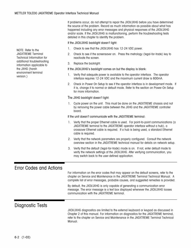
If problems occur, do not attempt to repair the JXOI/JXHG before you have determined the source of the problem. Record as much information as possible about what has happened including any error messages and physical responses of the JXOI/JXHG and/or scale. If the JXOI/JXHG is malfunctioning, perform the troubleshooting tests detailed in this chapter to identify the problem.
If the JXOI/JXHG backlight doesn’t light:
1. Check to see that the JXOI/JXHG has 12-24 VDC power.
2. Check to see if the screensaver on. Press the metrology (legal-for-trade) key to reactivate the screen.
3. Replace the backlight.
If the JXOI/JXHG’s backlight comes on but the display is blank:
1. Verify that adequate power is available to the operator interface. The operator interface requires 12-24 VDC and the maximum current draw is 600mA.
2. Check in Power On Setup to see if the operator interface is in development mode. If it is, change it to normal or default mode. Refer to the section on Power-On Setup for more information.
The JXHG backlight doesn’t light:
1. Cycle power on the unit. This must be done on the JAGXTREME chassis and not by removing the power cable between the JXHG and the JAGXTREME controller board.
If the unit doesn’t communicate with the JAGXTREME terminal:
1. Verify that the proper Ethernet cable is used. For point-to-point communications (a JAGXTREME terminal to the JAGXTREME operator interface without a hub), a crossover Ethernet cable is required. If a hub is being used, a standard Ethernet cable is required.
2. Verify that the network parameters are properly configured. Consult the network overview section in the JAGXTREME technical manual for details on network setup.
3. Verify that the default (legal-for-trade) mode is on. If not, enter default mode to verify the network settings of the JXOI/JXHG. After verifying communication, you may switch back to the user-defined application.
Error Codes and Actions For information on the error codes that may appear on the default screens, refer to the chapter on Service and Maintenance in the JAGXTREME Terminal Technical Manual. A complete list of error messages, probable causes, and suggested remedies is provided.
By default, the JXOI/JXHG is only capable of generating a communication error message. The error message is a text box displayed whenever the JXOI/JXHG looses communication with the JAGXTREME terminal.
Diagnostic Tests JXOI/JXHG diagnostics are limited to the external keyboard or keypad as discussed in Chapter 2 of this manual. For information on diagnostics for the JAGXTREME terminal, refer to the chapter on Service and Maintenance in the JAGXTREME Terminal Technical Manual.
NOTE: Refer to the JAGXTREME Terminal Technical Information for additional troubleshooting information applicable to the JXHG (harsh environment terminal version.)
Chapter 7: Parts and Accessories JXOI (Panel-Mount Version)
(1-03) 7-1
7 Parts and Accessories
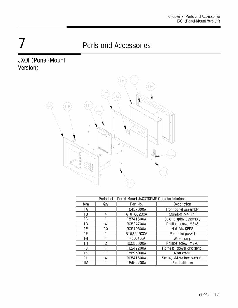
JXOI (Panel-Mount Version)
Parts List – Panel-Mount JAGXTREME Operator Interface Item Qty Part No. Description 1A 1 16457800A Front panel assembly 1B 4 A16108200A Standoff, M4, F/F 1C 1 15741300A Color display assembly 1D 4 R0524700A Phillips screw, M3x8 1E 10 R0519600A Nut, M4 KEPS 1F 1 B15894900A Perimeter gasket 1G 1 14665400A Wire clamp 1H 2 R0553300A Phillips screw, M2x6 1J 1 16242200A Harness, power and serial 1K 1 15895000A Rear cover 1L 4 R0541500A Screw, M4 w/ lock washer 1M 1 16452200A Panel stiffener
METTLER TOLEDO JAGXTREME Operator Interface Technical Manual
(1-03) 7-2
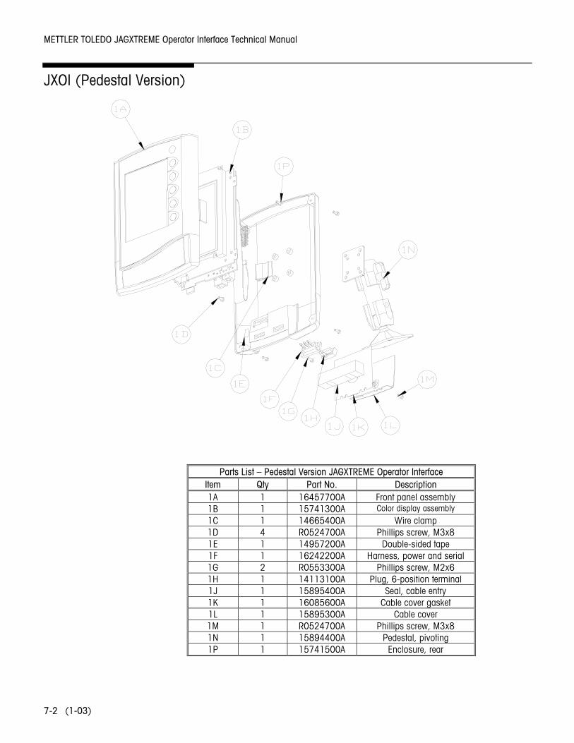
JXOI (Pedestal Version)
Parts List – Pedestal Version JAGXTREME Operator Interface
Item Qty Part No. Description 1A 1 16457700A Front panel assembly 1B 1 15741300A Color display assembly
1C 1 14665400A Wire clamp 1D 4 R0524700A Phillips screw, M3x8 1E 1 14957200A Double-sided tape 1F 1 16242200A Harness, power and serial 1G 2 R0553300A Phillips screw, M2x6 1H 1 14113100A Plug, 6-position terminal 1J 1 15895400A Seal, cable entry 1K 1 16085600A Cable cover gasket 1L 1 15895300A Cable cover 1M 1 R0524700A Phillips screw, M3x8 1N 1 15894400A Pedestal, pivoting 1P 1 15741500A Enclosure, rear
Chapter 7: Parts and Accessories JXHG (Harsh Environment Terminal Version)
(1-03) 7-3
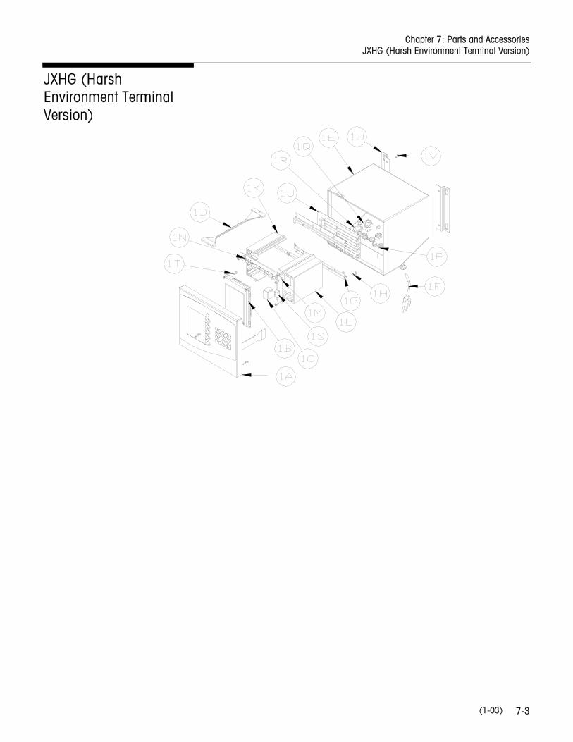
JXHG (Harsh Environment Terminal Version)
METTLER TOLEDO JAGXTREME Operator Interface Technical Manual
(1-03) 7-4
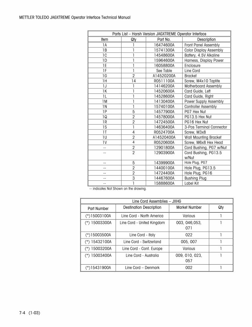
Parts List – Harsh Version JAGXTREME Operator Interface Item Qty Part No. Description 1A 1 16474600A Front Panel Assembly 1B 1 15741300A Color Display Assembly 1C 1 14548600A Battery, 4.5V Alkaline 1D 1 15964600A Harness, Display Power 1E 1 16058800A Enclosure 1F 1 See Table Line Cord 1G 2 A14520200A Bracket 1H 14 R0511100A Screw, M4x10 Taptite 1J 1 14146200A Motherboard Assembly 1K 1 14520600A Card Guide, Left 1L 1 14528600A Card Guide, Right 1M 1 14130400A Power Supply Assembly 1N 1 15740100A Controller Assembly 1P 5 14577900A PG7 Hex Nut 1Q 2 14578000A PG13.5 Hex Nut 1R 2 14724500A PG16 Hex Nut 1S 1 14636400A 3-Pos Terminal Connector 1T 4 R0524700A Screw, M3x8 1U 2 A14520400A Wall Mounting Bracket 1V 4 R0520600A Screw, M6x8 Hex Head -- 2 12901800A Cord Bushing, PG7 w/Nut -- 2 12903900A Cord Bushing, PG13.5
w/Nut -- 5 14399900A Hole Plug, PG7
-- 2 14400100A Hole Plug, PG13.5 -- 2 14724400A Hole Plug, PG16 -- 3 14467600A Bushing Plug -- 1 15888600A Label Kit
-- indicates Not Shown on the drawing.
Line Cord Assemblies – JXHG
Part Number Destination Description Market Number Qty
(*)15003100A Line Cord - North America Various 1
(*) 15003300A Line Cord - United Kingdom 003, 046,053, 071
1
(*)15003500A Line Cord - Italy 022 1
(*) 15432100A Line Cord - Switzerland 005, 007 1
(*) 15003200A Line Cord - Cont. Europe Various 1
(*) 15003400A Line Cord - Australia 009, 010, 023, 057
1
(*)15431900A Line Cord – Denmark 002 1

Chapter 7: Parts and Accessories Accessories and Options
(1-03) 7-5
Accessories and Options Part Number Description
0917-0311 Weighted Base for JXOI Pedestal Version
0917-0337 Network Splitter for JXHG

METTLER TOLEDO JAGXTREME Operator Interface Technical Manual
(1-03) 7-6
NOTES

METTLER TOLEDO 1900 Polaris Parkway Columbus, Ohio 43240 Phone: (US and Canada) (800) 786-0038 (614) 438-4511 Phone: (All Other Countries) (614) 438-4888 www.mt.com P/N: 16467300A (1-03).01 ©2003 Mettler-Toledo, Inc. Printed in USA
16467300A