Embed Size (px)
Citation preview
TGCHNICAL REPORT "1-78-17
FEASIBILIT Y STUDY OF AN EARTH MELTINGPENETRATOR SYSTEM FOR GEOPROSPECTING
TUNNEL RIGHT-OF-WAYSby
D. L. Black'Westinghouse Advancod Energy
Systems DivisionLarge, Pennsylvania 15025
December 1978c2D Final Report
Approved For Public Release; Distrib ution un Iimtj
-4L
-- -.
Prepared for Office, Chief of Engineers, U. S. Army /j ~ cWashington, D. C. 20314 D D C
Under Contract No. DACW 39-76-C-0 163 APOR 17 1979
Monitored by Geotechnical LaboratorypU. S. Army Enginoer Waterways Experiment Station T Li D
P. 0. Box 631, Vicksburg, Miss. 39180 D
1 7 j 8 174

Destroy this report when no longer needed. Do not returnIt to the originator.
The findings in this report are not to be construed as an officialDepartment of the Army position unless so designated
by other authorized documents.

UnclassifiedSECURITY CL SI ICATION OF THIS PAGE filho Vae. Entec.)__________________
RFQTNTATION PAGE 89FORZ COMPLETIN FORM
Technical Rmep% - -
EASIBILITY 4TUDY OF AN JARTH B1ELTING SENETRATOR 'i
/j 0D.1. Black M606 I'
SPElrPORMIN ORGANIZATION NAME AND ADDRESS "GRMEMNTPOJCAS
Westinghouse Advanced Energy Systems Divis4enLarge, Penn. 15025 3[~ ~ Ofc U. S. f Ar Engineertras, Expe.rmeny tto
Geotechnical Laboratory UnclassifiedP. 0. ox 631IS&. DCI.C ASSI PIC ATION/ODOWN GRADING
Vicksburg, Miss. 39180 SCHDULE
IS. DISTRIBUTION STATEMENT (at this Repori)
Approved for pu]c.xaai istribution unlimited.
I ~ 17. DISTRIOUTION STATEMENT (of the abstract eftered In block 20. It different ham Repoil)
Ill. SUFPLEMNTARY NOTES
Drilling Penetration Soil penetrationEarth melting penetrators Penetrators Subsurface explorationFeasibility studies Right of way TunnelsGeophysical exploration Rock meltIin ettrc o~fdrJ~~nI~ponjgs19. IEV WORDS (Contnue on reverse side i necessary end idflifab block nuembo,)
W SR*VUAcT(rAmeninse vwm.vsisNnuseesow nd lmgality by black momber)
The Earth Melting Penetrator (EMP) is a concept utilizing high-temperaturepenetrator tips at the leading end of a length of nonrotating stem to meltearth materials in its path and leave an open hole for geologic explorationpurposes. The early proof-of-concept testing was performed by the Los AlamosScientific Laboratory. Westinghouse Corporation Advanced Energy Systems Divi-sion developed a conceptual design and cost estimate for a technically feasible
EMP system (including heater, core handling, power transmission, and power--DO ,J~S103 Em1OW@VMOVSISUSOETE nclssiied(Continued)
P7 SECURITY CLASSIFICATION Of THIS PAGE (When Dot* Entered)
Unclassi fledSecur"TV CL. ANFICATION OP THIS PAGG(fmr a b te"i9d
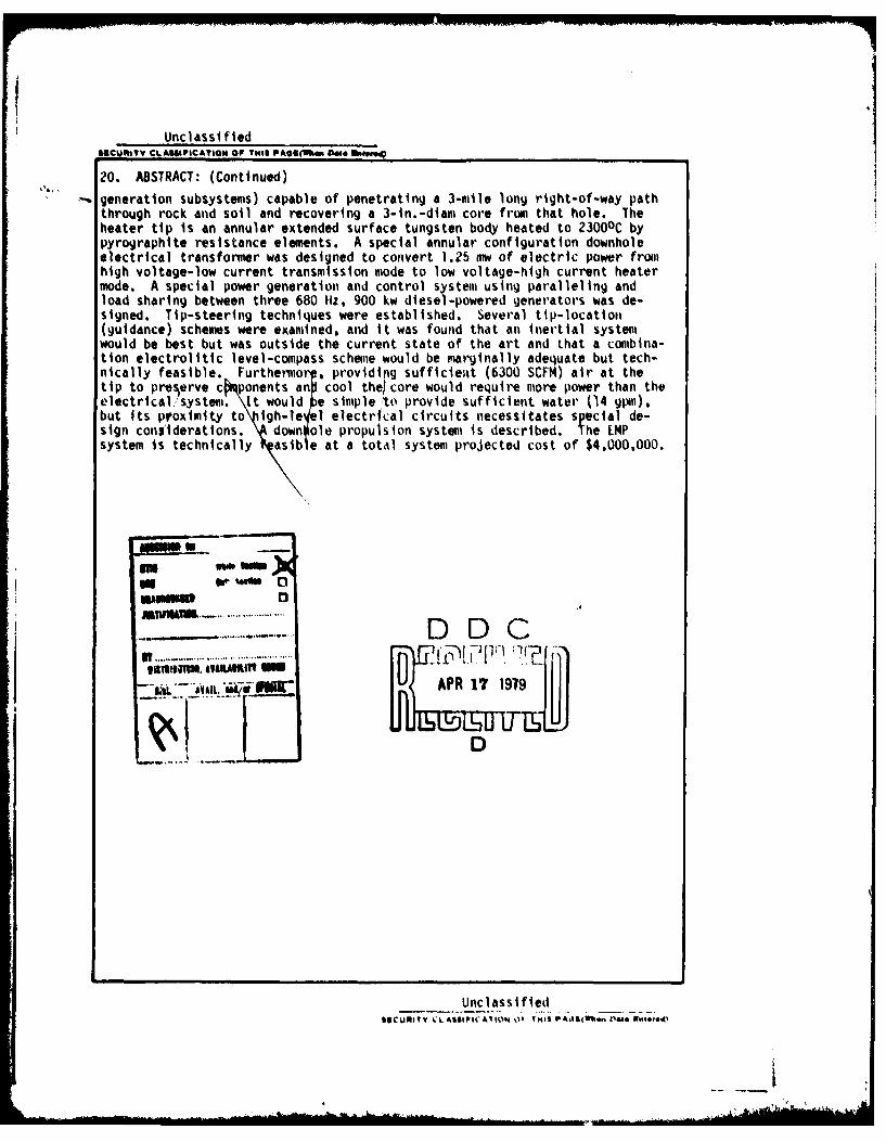
20. ABSTRACT: (Continued)
-, generation subsystems) capable of penetrating a 3-mile long right-of-way paththrough rock and soil and recovering a 3-in.-diam core from that hole. Theheater tip is an annular extended surface tungsten body heated to 23000C bypyrographite resistance elements. A special annular configuration downholeelectrical transformer was designed to convert 1.25 nw of electric power fromhigh voltage-low current transmission mode to low voltage-high current heatermode. A special power generation and control system using paralleling andload sharing between three 680 Hz, 900 kw diesel-powered generators was de-signed. Tip-steering techniques were established. Several tip-location(guidance) schemes were examined, and it was found that an inertial systemlwould be best but was outside the current state of the art and that a comubina-tion electrolitic level-compass scheme would be marginally adequate but tech-nically feasible. Furtheorp, providi g sufficie;%t (6300 SCFM) air at thetip to preserve c ponents an cool the core would require more power than theelectricalsyste.it would e simple to provide sufficient water (14 gipm),but its proximity to igh-le el electrical circuits necessitates special de-sign considerations. Ndown ole propulsion system is described. The LMPsystem is technically asible at a total system projected cost of $4,000,000.7
m ~~qU ..~ .... ...............
I,,,....... ......... ........ .. .... ......... ...... , ,.,,, m..-- Pou PR 1' 1919
D
UnclassifiedSISCURITY CL ASS tIC AMI)N W I "I I I'Ad . ..t " l01 NWreet

THE CONTENTS OF THIS REPORT ARE NOT TO BE
USED FOR ADVERTISING, PUBLICATION, OR
PROMOTIONAL PURPOSES. CITATION OF TRADE
NAMES DOES NOT CONSTITUTE AN OFFICIAL EN-
DORSEMENT OR APPROVAL OF THE USE OF SUCH
COMMERCIAL PRODUCTS.
PREFACE
This investigation was authorized by the Office of the Chief of Engineers (OCE)
under the Civil Works Research Program. The work reported herein was accomplished under
Contract No. DACW 39-76-C-0163 between the USAE Waterways Experiment Station, Vicksburg,
Mississippi (WES) and Westinghouse Advanced Energy Systems Division, Large, Pennsylvania.
Funding was provided in equal parts by the OCE, by the National Science Foundation (NSF),
and by the Department of Transportation (DOT). The work was initiated 26 October 1976
and completed 30 March 1978.
The designated Contracting Officer's Representative monitoring the contract
work was Mr. James B. Warriner (WES) who also prepared the Requirements Definition,
Part III of this report. Acknowledgement is given for critical advice and support to
Messrs. Jerry S. Huie and Don C. Banks, Chiefs of the Rock Mechanics Applications Group
and the Engineering Geology and Rock Mechanics Division, respectively, of the Geotechnical
Laboratory, WES; William W. Hakala, NSF; Russell MacFarland, DOT; Paul Fisher and
Wayne McIntosh. OCE; and Robert G. Hanold, Los Alamos Scientific Laboratories, Los Alamos,
New Mexico. Commander and Director of WES during the period of the contract was COL J. L.
Cannon. Technical Director was Mr. F. R. Brown.
Principal contributors to this study and report include the following:
1. 0. L. Black, Project Manager
2. M. Gibbons, Westinghouse Geophysical Instrumentation, Guidance
3. B. R. Krasicki, Air Flow Analysis
4. W. L. Lundberg, Heat Transfer Analysis
5. F. S. Spurrier, Mechanical Design
6. M. Vuchovich, Electrical Design
7. M. K. Wright, Development Plan and Engineering Management
CONTENTS
PREFACE 2
CONVERSION FACTORS, METRIC (SI) TO U. S. CUSTOMARY ANDU. S. CUSTOMARY TO METRIC (SI) UNITS OF MEASUREMENT 4
PART I.- EXECUTIVE SUMMARY 5
Introduction 5Requirements Definition 6Conceptual Designs 8Cost Evaluation 13Selected Penetrator Design 14Development Program 24
PART II.- INTRODUCTION 26
Bacikgrond 26Study ObjectiveWorks~ Statements 2
PART III: REQUIREMENTS DEFINITION 30
backcground 30Hle 31Liner 35Corm/Extwdite 37Groundmaoss 39
PART IV. CONCEPTUAL ESEIGNS 41
System Performnce Analysis 41Power and Thrust 46Groundmnass 55Hole Logging 10Mechanical DesignElectrical Design 86
PART V: COST EVALUATION 109
Design Selection 109Cost Summary III
PART VI: SELECTED PENETRATOR DESIGN 115
Mechanical and Structural 115Electrical 1&17ThewoV~ydroulic 131
PART VII: DEVELOPMENT PROGRAM 146
Phase 11I- Prototype Penetrator Demonstraton 146Phase III - System Acquisition 149Phase IV - System Operation 151Estimated Contract Resources12
REFERENCES 154
3
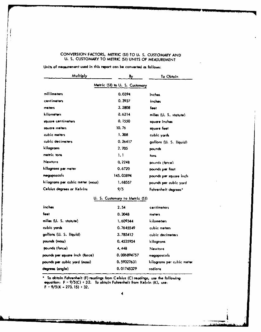
Cnl O NVRINFCTRMTI (SI) TOwU S. CUSTOMARY AND
_________________By___To Obtain
Metric (SI) to U. S.-Custo
mliee%0.0394 Inches
cniees03937 Inches
moters 3.2808 feet
kilometers 0.6214 miles (U. S. statute)square centimeters 01550 square Inches
square motors 1076 square feet
cubic meters 1. 308 cubic yards
cubic decimeters 0. 26417 gallons (U. S. liquid)kilograms 2.205 pounds
metric tons 1.1 tonsNewtons 0. 2248 pousnds t(orco)
kilograms per meter 0.6720 pounds per foot
megaposcals 145. 03894 pounds per square Inchkilogram per cubic meter (moss) 1.68557 pounds per cubic yard
Celsius degrees or Kelvins 9/S Fahrenheit degrees"
U. S. Customary to Metric (SO)
Inches 2.54 centimeters
feet 0. 3048 meters
miles (U. S. statute) 1.609344 kilometers
cubic yards 0.7645549 cubic meters
gallons (U. S. liquid) 3.785412 cubic decimeters
pounds (mass) 0.4535924 k ilograms
pounds (force) 4.448 Newtons
pounds per square Inch (force) 0.006894757 megopascols
pounds per cubic yard (mass) 0.59327631 kilograms per cubic meter
degrees. (angle) 0.01745329 radians
*To obtain Fahrenlieft (F) readings from Celsius (C) readings, use the followingequation: F 9/5(C) + 32. To obtain Fahrenheit from Kelvin (K, use-F ' 9/5(K- 273. 15) + 32.
4
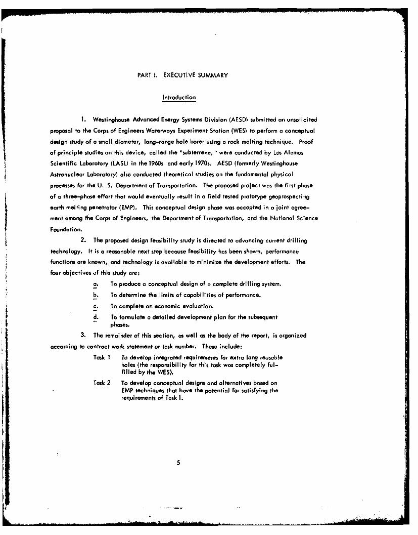
PART 1. EXECUTIVE SUMMARY
Introduction
1. Westinghouse Advanced Energy Systems Division (AESD) submitted an unsolicited
proposal to the Corps of Engineers Waterways Experiment Station (WES) to perform a conceptual
design study of a small diameter, long-range hole borer using a rock melting technique. Proof
of principle studies on this device, called the "subterrene, " were conducted by Los Alamos
Scientific Laboratory (LASU in the 1960s and early 19 7 0s. AESD (formerly Westinghouse
Astronuclear Laboratory) also conducted theoretical studies on the fundamental physical
processes for the U. S. Department of Transportation. The proposed project was the first phase
of a three-phase effort that would eventually result in a field tested prototype geoprospecting
earth melting penetrator (EMP). This conceptual design phase was accepted in a joint agree-
ment among fhe Corps of Engineers, the Department of Transportation, and the National ScienceFoundation.
2. The proposed design feasibility study is directed to advancing current drilling
technology. It is a reasonable next step because feasibility has been shown, performance
functions are known, and technology is available to minimize the development efforts. The
four objectives of this study are:
a. To produce a conceptual design of a complete drilling system.
b. To determine the limits of capabilities of performance.
c. To complete an economic evaluation.
d. To formulate a detailed development plan for the subsequentphases.
3. The remainder of this section, as well as the body of the report, is organized
according to contract work statement or task number. These include:
Task I To develop integrated requirements for extra long reusableholes (the responsibility for this task was completely ful-filled by the WES).
Task 2 To develop conceptual designs and alternatives based onEMP techniques that have the potential for satisfying therequirements of Task 1.
I5
5I
Task 3 To perform a qualitative assessment of the relative tradesamong the concepts and parameters identified in Task 2.
Task 4 To provide visual, narrative and analytical descriptionsof the reference system concept.
Task 5 To provide a logical development program for advancementof the reference system concept into detailed design, des el-opment, fabrication and field testing.
Task 6 To provide technical coordination and project management.
Requirements Definition
4. The system requirements as stated herein were assembled entirely by WES
personnel from specifications and recommendations set forth by Engineering Manuals of the
Corps of Engineers, the American Society for Testing Materials, the International Society
of Rock Mechanics, the Breau of Mines Reports, and the Bureau of Reclamation Reports.
Together, these requirements are intended to represent the best concept of the equipment
design features, the necessary characteristics of the EMP created hole, characteristics of
the EMP recovered core, and the areas of further investigation into the lithologic effects
of tunneling a melted hole into a groundmoss.
5. Five potential applications for EMP-created holes listed in order of decreasing
projected importance were identified: core sampling recovery, geophysical logging, mechani-
cal/fluid testing, conduits for utilities, and fluid transfer. Consistent with these uses, a
quantitative description of EMP requirements was compiled and subdivided into four categories:
hole, liner, core/extrudite, and groundmass. A summary of these quantitative requirements
is given in Table 1. Those requirements that cannot be expressed quantitatively were excluded
from this table and are summarized i, the following paragraph.
6. The necessary ground support equipment must obtain sufficient electric power
for all operations from commercially available mobile generators, and transformers, compressors,
and other large equipment must be highway transportable. Air is the preferred coolant medium
because of its universal availability, but water is acceptable. The control and operating console
should be capable of real time representation of tip location. Protective equipment must be
provided for the possibility of inadvertent steam or other volatile release from the portal area
under high pressure.
6
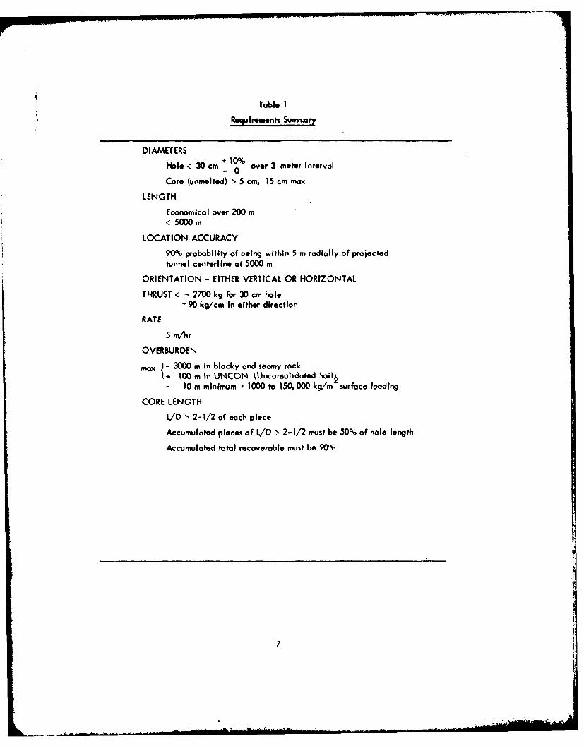
Table 1
RequIrements Sumnar
DIAMETERS
Hole < 30 cm -0over 3 meter interval
Core (unmelted) '> 5 cm, 15 cm max
LENGTH
Economical over 200 m< 5000 m
LOCATION ACCURACY
90% probability of being within 5 m radially of projectedtunnel centerline at 5000 m
ORIENTATION - EITHER VERTICAL OR HORIZONTAL
THRUST < - 2700 kg for 30 cm hole- 90 kg/cm In either direction
RATE
5 mV~w
OVERBURDEN
max ~ 3000 m In blocky and seamy rockt-100 m In UNCON kUnconsolisdated Soil~
-10 m minimum + 1000 to 150, 000 kg/in surface loading
CORE LENGTHL/D N~ 2-1/2 of each piece
Accumulated pieces of L/D '- 2-1/2 must be 50% of Woe length
Accumulated total recoverable must be 90%
7
7. The nature of the material comprising the glass liner is important to the correct
usage and interpretation of geophysical logs in the hole. This required that an estimate be
mode of the composition of the liner, as well as its elastic and fluid flow properties and the
effect of the liner on measured physical phenomena. Besides the liner, the thermal history
of the recoverable core must have a minimal perturbation on the potential mineralogic and
hydrologic effects. Exterior to the glass liner in the parent medium, the effects of heat wave
propogation on other structures such as utility conduits also must be minimized.
8. The EMP must have a universal penetrating capability. Calculations on its
design and performance should be made using all five geologic models derived in the earlier
DOT study.
Conceptual Designs
9. Prior to initiating design work, a parametric study on size and performance
variables was completed to develop preliminary evaluations of system requirements. These
were further divided into geometry, power and thrust, and groundmass effects in an effort
to parallel the preceding requirements section. Within the diametral constraints of ID greater
than 50 mm and OD less than 300 mm, the power and flow requirements will be minimized for
the smallest size penetrator, but down-hole equipment packaging becomes more difficult.
For the parametric study it was estimated that 200 mm is the smallest hole diameter that
could conceivably accommodate such down-hole equipment as guidance electronics and trans-
formers. Performance calculations, therefore, concentrated on evaluations at 200 and 300
mm diameters with a 50 mm core.
10. The structural requirements of the liner to sustain all overburdens at a depth
of 100 m, in addition to specified surface loading, is an independent variable and can be
evaluated. Based on a conservative model of the earth overburden, called a condition of
"restrained lateral deformation, " at the depth of 100 m in UNCON, the required liner
thickness/radius ratio is 0. 046 as determined by the nominal tensile strength of the glass.
Considering surface loading as a hydrostatic column on the UNCON model, the equivalent
depth is doubled to 200 meters.
8
11. The generalized mass balance was derived for the configuration relating the
linear geometry to the melted rock and penetrator velocities. These can be related to the
internal flow areas of the penetrator head in order to obtain the proper liner thickness. The
ratio of the extrudite to penetrator velocity of approximately 20 gives this desired linear
thickness within the range of the dimensions and model densities considered.
12. Using the energy and temperature equations developed in the DOT study, the
heater power and penetrator surface temperatures were calculated for the two diameters and
five geological models as functions of penetrator velocity. The CALCI model has the highest
melting point and consumes the most power because nearly 40 percent of its energy is consumed
in CO 2 evolution. At the maximum penetration velocity of 1.4 mm/sec, the CALCI model
power requirement is 509 kW for the 0. 2 m diameter hole, and 1078 kW for the 0. 3 m
diameter hole. The power required to penettate at the same velocity through UNCON is
approximately half that of CALCI.
13. Although the predictions of heater pover are based on LASL test data and are
considered reasonably accurate, the prediction of surface temperature by simple analysis
is much more difficult. The thermal conductivity of liquid rock is an unknown quantity and
significantly increases the uncertainty in the analysis. The parametric evaluation of the
surface temperature was performed on the basis of correlations developed in the DO study
and the thermophysical properties developed therein. The results indicate that temperatures
in excess of 2300 K, considered to be the maximum operating temperature for the materials
under consideration, are exceeded for most operating velocities and geological models,
assuming a simple surface geometry and a length to diameter ratio of 1.5. Substantial
reduction in operating temperature can be achieved by increasing the L/D ratio and
incorporating fins on the exterior surface of the penetrator.
14. The applied thrust load was calculated for all geologic models based on the
maximum depth of penetration for 200 m equivalent depth. The results show that the maximum
force required is 105 newtons including the drag of the stem on the liner.
15. An analysis of the sheet wave penetration into the groundmass was performed
using a transient digital computer code. the UNCON and MASIG geological models are,
respectively, the least and most conducting respectively, and these were considered. During
the time of penetrator passage, the MASIG temperature changes were restricted to an area
9
. .. _. -- i - . . . .. II~l i11 I I IrlU ... " ' . ... . ... . ... . I 4
within a 20-inch radius of the EMP centerline, and the liner cooling air can withdraw
much of the energy added to the earth by the EMP within one hour after passage of the pene-
trator. During this period the centerline temperature of the core increased only 150OF beyond
the ambient for the nominal penetrator temperature and velocity. At the maximum penetration
velocity of 1.4 mm/sec the outside surface temperature of the retrievable core reached 10000 F.
16. Two principal changes occur during the passage of the penetrator. First,
the groundmass temperature is temporarily elevated;, second, a glass liner is formed. Each
of these can affect logging results as described in the following parogl-?hs.
17. Igneous rocks acquire most of their magnetism as they cool through the Curie
temperature. Temperature distribution analyses indicate that the 850 K isotherm (Curie
temperature) does not extend more than five inches from the penetrator. However, the
natural remanent magnetism can be increased up to a factor of 5. In the volume of rack that
exceeds this temperature, the factor increases with the age of the rock.
18. Dehydration of the surrounding rock and the rock in the liner will affect the
calibration of all neutron logs. Neutron logs will be usable for quantitative analysis in EMP
created holes if the instruments are calibrated in ait environment that simulates this hole.
This recalibration is required because the neutron slowing-down length is increased, which
is attributable to the decrease in the macroscopic cross section at epithermal energies caused
by the hydrogen being driven from the rock.
19. Seven geophysical lags were investigated to determine the effect of the heated,
glass-lined hole. Electrical induction logs, gamma logs, and density logs should be useful.
It is doubtful that spontaneous potential logs, guard logs, and electrical logs will produce
satisfactory results. The utility of acoustical logs is dependent upon the type of groundmass.
20. Six mechanical design concepts were developed and evaluated, based
primarily on the LASL technology, in an effort to keep future development requirements
at a minimum. The first concept, a removable core barrel and wire line, mode provision
for the removal of the undisturbed core, section by section, as penetration proceeded. The
inner diameter of the penetrator accommodated a core barrel several feet long into which
the core was to be extruded. As the core completely filled the barrel, the release mechanism
was activated and the core barrel and core could be withdrawn to the portal by means of a
wire line. After removal o the core from the barrel at the portal, the core barrel was
then reinserted into the penetrator stem and propelled by compressed air to the penetrator head
location to await its reset and refilling.
10

The penetrator head, machined from tungsten, accommodated 12 cylindrical heaters in
equally spaced axial holes around the penetrator axis. Molten rock was fed through a series
of holes and grooves machined in the penetrator head to 12 carry-off tubes equally spaced
around the penetrotor axis. These are connected with an annular carry-off passage in the
stem. High pressure air was applied to the outer passage at the portal. It flowed to the
penetrator where it entered the injection nozzles at the penetrator end of the carry-off
tubes. Molten rock extruding into the carry-off tubes was then solidified and fluidized by
the high velocity air emerging from the nozzles and transported pneumatically to the surface.
21. The second concept incorporated a cooling passage arrangement at the inside
diameter of the penetrator head to remove heat from the core in an attempt to limit the
temperature of the core at its entry into the penetrator bore and thus maximize the diameter
of the thermally undisturbed portion of the core. In other aspects, this design was generally
similar to concept no. 1.
22. In the third concept, the 12 separate cylindrical heater geometry was replaced
by an annular corfiguration divided into three 1200 sectors. This three-sector arrangement
was intended to provide the necessary steering capability by appropriate modulation of the
power to the three sectors. The location of the heaters in the heater annulus was effected
by a system of spring-loaded tungsten electrodes similar to that employed in the previous
two concepts.
23. In concept no. 4 the annular heater arrangement was used together with four
separate carry-off tubes. In this arrangement the inner diameter of the penetrotor was
insulated from the centering core by pyrographite tubes and no provision was made for
cooling the core. Molten rock was fed to the carry-off tubes through drilled passages
from a circumferential groove in the penetrator periphery. This, in turn, received molten
rock from the extended surface fins machined axially along the penetrator.
24. The fifth arrangement contained nine heaters with three carry-off tubes.
This arrangement provided three independently controllable heating sectors, each of which
contained three resistance heater elements, constituting the load of a three-phase circuit
Nine transformer modules were accommodated in the stem in three groups of three within
the spaces between the three carry-off tubes.
I1
25. Although generally similar to the previous concept, this lost desigi ncosporutes
three large diameter axial holes drilled from the loading edge of th ponetratoi inI lin'e with
the carry-off tubes. Pooviiion was niade to accommodate tire flow of a large por tion of
the molten rock directly from the leading edge of the penettiot. Thus, the designi provided
for the flow of molten rock from both ends of the penetrator head.
26. For the electrical design of the EMP, Individual studies wets made of heater
configuration and material, the down-hole stem transfornier, the power transmission, kind the
up -hoe surface powei suppiles.
27. Both tungsten filament and pyrographite heoaters were originally consideged.
However, because heater flux denisities must be high to produce thre required temperatures
and consideration must be given to slight vibrations within CIOs* tolrances, wiho f'lilmnt
and filament mesh heaters were ollmin~sted. Calculations were moide for pyrographite heaters
25. 4 mm in diameter and 25. 4 cm long for various power and voltage combinations. The
ultimate seluction of operating voltage for the heaters Is a trade between the desire to hove %I
low-voltage and minimum sparking potential inI the heater and tire desire fog high voltage with
Its low loss in transnission~.
285. To minimize large transmission losses for aI system length of 5000 mi, the pos-
sibility of installing step-down transformers in the stem behind the penetrkitot was investigoted.
The maximum cinnuli spce allowed fog the tiansfomers was 8. 255 cmi. '\ conitinuing
Investigation Into transformer designi inidicated that .I troinsforrier could be built to power
the heaters, but to meet the diameter envelope each transformer phose would have to be
59 ft long uing typical 60 H.- power. Since niine heaters ar* used and only one* three phase
tfonsfomier could be placed In a steni section. the stem length required to accommodate thetransformers olone would be approximately 180 ft. If the frequenicy of th. power Is incteased,
the stem hasoromot size could be proportionately dlecreaosed.
2Y. At the heater voltages considegeid, the total current etiquitenieiit would be
in excess of 1000 amperes isI older to achieve 1. 25 MW. Tionsmiitting c'uritentts of this
magnitude for 5000 moetors would rsult In extremely high losses in addition to ttequitlng
lar ge cable diameters. Cosiidering heater trionst and ti ansmi ssion linie choroc ten stic%
a swambes six cable was selected, with the source transniission voltage to fall between 2600
and 5000 volts, at a frequency of 680 Hz.
12
30. Four options for power supplies were developed by considering only self-
contained trailer mounted units. These options considered paralleling, load sharing, and
synchronizing. The selected option contains three generators sized such that any two
generators can supply power to all three heaters. Paralleling and load sharing controls am
provided.
31. The problem of accurate guidance through the earth Is complicated by
the inhomogeneous, hostile, and unpredictable medium. Guidance of the earth melting probe
must be approximately 5 feet in 5000 feet or + 0. 1 percent; data gathering must be nearly
continuous. If the guidance system is in the probe, then the guidance package must be
insulated from temperatures from 2000 to 2500 K. Several types of systems were investigated
with respect to their size and accuracy. These included seismic, magnetic, electromagnetic,
optical and inertial. Only the inerted could fulfill the accuracy requirements. However,
size, packaging and environment problems were not completely solved. A hybrid possibility
includes the inertial guidance system and an arrangement of electrolytic levels and a compass
that would give pitch, roll and direction or yaw. This arrangement represents the cheapest
available working system, assuming successful interface and test. However, the electro-
static gyro compass must provide continuous yaw data. Therefore, only the inertial naviga-
tion system gives continuous real time data on roll, pitch, and yaw within the desired
accuracy. Here the major obstacle was size and, although a smaller system exits, data on
drift and environmental tolerances are classified.
Cost Evaluation
32. The cost evaluation consists of the rationale for selecting the reference design
and some preliminary cost estimates for the entire system. Although all six configurations
were deemed 6easible, the provision made in concept no. 6 for augmenting the heat flow
to the penetrator leading edge by mass transport of the rock made this the most potentially
useful design feature and it was therefore retained as a selected concept. Although it is
anticipated that propulsion of the penetrator head will be achieved by applying the com-
13
pressive force to the stem at the portal, a self-contained down-hole propulsion module was
also defined conceptually. Because of the added complexity and lower reliability associated
with moving ports, this propulsion concept was not given further consideration.
33. A cost estimate was developed for the reference concept description derived
primarily from conversations with potential vendors and is in terms of 1977 dollars. A
summary of the mechanical and electrical system costs is given in Table 2. A total cost
for the system (assuming no government-furnished equipment) is slightly less than $4,000,000.
The two largest cost items ore three miles of stems and the electrical generator for the heater,
which are about $1,000,000 each. Costs do not include trailers for housing personnel, fuel
and water trailers, control room trailers, communication system, or general facility inter-
connec tions.
Selected Penetrator Design
34. The selected earth melting penetrator configuration is illustrated in Figure 1.
The penetrator head is made of tungsten having a melting point of 3683 K which is 800 K
above that of molybdenum. Actual operating temperature will be substantially below these
melting points. The manufacturer of the tungsten penetrator head involves the initial
pressing and sintering of 92 percent density blanks, which must then be further densified by
forging. Since available press size is limited, the penetrator head will be comprised of
diffusion-bonded laminations. The penetrator head has axial fins machined in its exterior
surface. The large diameter hole is machined along its centerline, which accommodates
tungsten, pyroqrophite, and molybdenum rings that together function as the core former. Twelve
holes are machined axially in the penetrator. Three of these holes provide a flow path for
the molten rock and the other nine are arranged in three equally spaced groups of three
hles to accommodate the nine resistance heaters. Each heater consists of a cylindrical
stack of pyrographite and graphite discs held in position by compressive force transmitted
through a spring-loaded tungsten electrode. The transition tube assembly consists of a
molybdenum tube of sufficient length to provide the necessary thermal isolation of the stem
from the penetrator. Control thermocouples are also accommodated in drilled holes in the
14
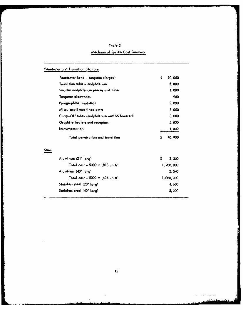
Table 2
Mechanical System Cost Summary
Penetrator and Transition Sections
Penetrator head - tungsten (forged) $ 50,000
Transition tube - molybdenum 5,003
Smaller molybdenum pieces and tubes 1, 000
Tungsten electrodes 900
Pyrographite insulation 2,000
Misc. small machined parts 3,000
Carry-Off tubes (molybdenum and SS bronzed) 3,000
Graphite heaters and receptors 5,030
Instrumentation 1,000
Total penetration and transition 70,900
Stem
Aluminum (21' long) $ 2,300
Total cost - 5000 m (813 units 1,900,000
Aluminum (40' long) 2,540
Totul cost - 5000 m (406 units 1,000,000
Stainless steel (20' long) 4,600
Stainless steel (40' long) 5,030
15
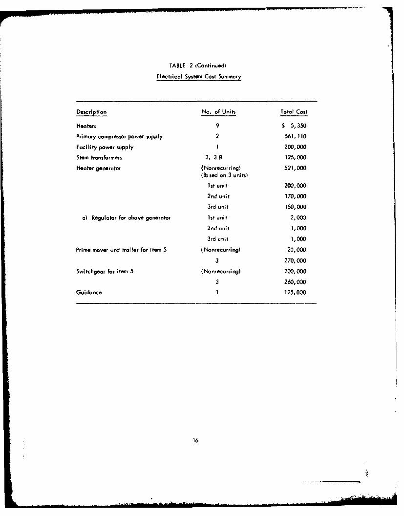
TABLE 2 (Continued)
Electrical Sys tern Cost Summary
Description No. of Units Total Cost
Heaters 9 S 5,350
Primary compressor power supply 2 561, 110
Facility power supply 1 200,000
Stem transformers 3, 30 125,000
Heater generator (Nonrecurring) 521,000
(Based on 3 units)
lI t unit 200,000
2nd unit 170,000
3rd unit 150,000
a) Regulator for above generator 1st unit 2,003
2nd unit 1,000
3rd unit 1,000
Prime mover and trailer for item 5 (Nonrecurring) 20,000
3 270,000
Swltchgear for item 5 (Nonrecurring) 200,000
3 260,030
Guidance 1 125,030
16
cwcfl. now.
san, caMP
609r - 1, rRw 'Ow ne e Sam, N0 1
0 79,,-QWefo FIN MI7~a OrC r
A0" Io tro
-4- a-.j-'-. B-' 1
-s 7. --.7=1 ------ - - -- _--A nm- - -
4 0
* 0~ 0 .-
7-7
Figur 1. Seete athmlin eetao
0ofgrto

penetrator head. Helium gas is supplied to the heater cavities of the penetrator to provide
an inert atmosphere.
35. An assembly of standard stem sections joined end to end by split clamps
forms the overall drill string. Specially modified stem sections accommodate transformer
modules, guidance equipment, and control boxes. The standard stem section is fabricated
from standard sizes of aluminum pipe. The outer casing of 10.75 in. diameter by 0.2 in.
thick pipe is welded at each end to machined aluminum end fittings. End fittings provide
support for a central 3.5 in. diameter x 0. 12 in. thick pipe and 3 1.90 in. diameter x
0.065 in. thick pipes equally spaced around the central pipe. Rubber O-rings are used to
seal the smaller tubes to the end fittings and to seal the stem sections to each other. The
end fittings also provide support for nine male and female electrical connectors, thermo -
couple connectors and the helium line.
36. By using a power source frequency of 680 Hz, the overall transformer stem
length was reduced from 180 ft. to 30 ft. The transformer primary and secondary are
wound around microlaminations and could be made in small sections about 15 in. long x
3.5 in. in diameter. These small sections are stacked in series like cells in a flashlight
until the proper operating voltages are achieved for the primary. All the secondaries are
connected in parallel to a common bus for that phase.
37. Generators to provide the power requirements for the system are expected
to be 18 in. in diameter and 48 in. long with an estimated weightof 1600 lbs. To produce
680 KV frequency, the generators may have to be turbine driven. Additional generators
are required for foc ility power and air compressor power. Figure 2 shows the system block
diagram for the entire electrical family.
19
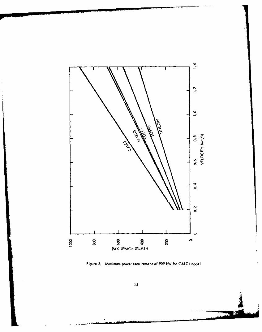
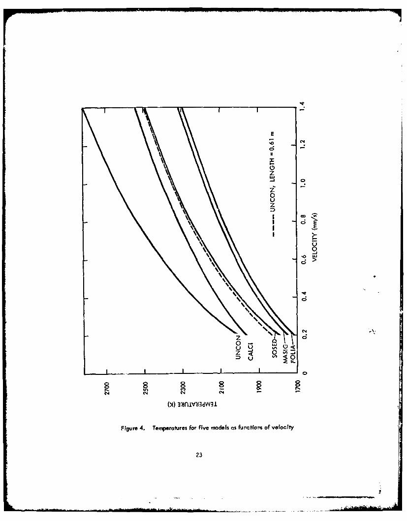
38. Power and temperature were calculated for the reference design configura-
tion in all geological models using the same techniques previously described. The maximum
power requirement of 909 kW is shown in Figure 3 for the CALCI model at 1.4 mm/sec
(5 m/hr) velocity). The maintenance of an operating temperature level less than 2300 K
continues to be a problem even with the extended surface geometry (fins). The low thermal
conductivity of the UNCON model results in that operating temperature at velocities of
0.4 mm/sec. Doubling the length of the penetrator to 0. 61 m would increase its allowable
operating velocity to 1.0 mm/sec. Temperatures for all five models are shown in Figure 4
as a function of velocity.
39. An analysis of the air cooling supply was made for the reference conceptual
design. The purpose of the air coolant supply is threefold: to provide coolant for internal
parts (e.g., guidance baggage); to cool the glass liner until it becomes self supporting; and
to provide floatatlon for the extrudite cooling and removal. Assuming the maximum allow-
able pipe temperature is 400OF for the aluminum stem configuration, and that the maximum
power that can be extracted is 600 kW, the maximum air flow requirement is approximately
8 lb/s*c. (6300 SCFM). For a flow of water at pressures greater than 250 psia, only two
pounds per sec. (14 gpm) is needed. If steel pipes were used instead of aluminum, air
flow rates of 3 to 4 lbs. per sec. could be used because of higher allowable material tem-
peratures.
40. Pressure drop calculations were made to determine the feasibility of supplying
this quantity of air to the end of a 5000 meter hole. The conclusion of a series of calcula-
tions is that 8 Ibsisec of air cannot be provided to the penetrator head at distances of 5000
meters within a moderate compressor outlet pressure of 1000 psia. In order to obtain suffi-
cient flow area to reduce the pressure drop, a stem OD ot approximately 14 in. may be
required. This is based on the requirement of at least 2. 5 in. diameter carry-off or
pneumatic mucking tubes, which in the currentdesign configuration have greater than
1000 psi pressure drop. These pneumatic mucking tubes require a minimum air velocity of
78 ft. per sec. in order to maintain the fluidization of the particles to transport them to
the surface.
41. Within the present geometric constraints of a 12 in. diameter and 3 mile
hole, the water pressure drop and pressure level (to prevent boiling) are not a problem since
only 500 psia pump pressure is required at 14 gpm.
20
I I I I .IIJ~
itr1fl~-. --C-
LW
~ 1
P1
U
~..v.
1L1
I ,~I
t *1
,~ -t',
~' ~
1j1
*I .~ Cl*1 iI
'I '~-
. Q'v:Kr -
* .. C' 4' .. {' 4'
Figure 2. System block dic~ram for electrical facility
21
7--
00
*'1
100(MI) SMOJ OW
Figure ~ ~ ~ ~ 4 3.Mxmmpwe-eurmnto70- Wfo AC oe
Z2
CI
zI-
z
0Uz
0
C4
Z 0
D 10
c-% (' C~4 %
Figure 4. Temperatures for five models as functions of velocity
23
DeveloPment ProVram
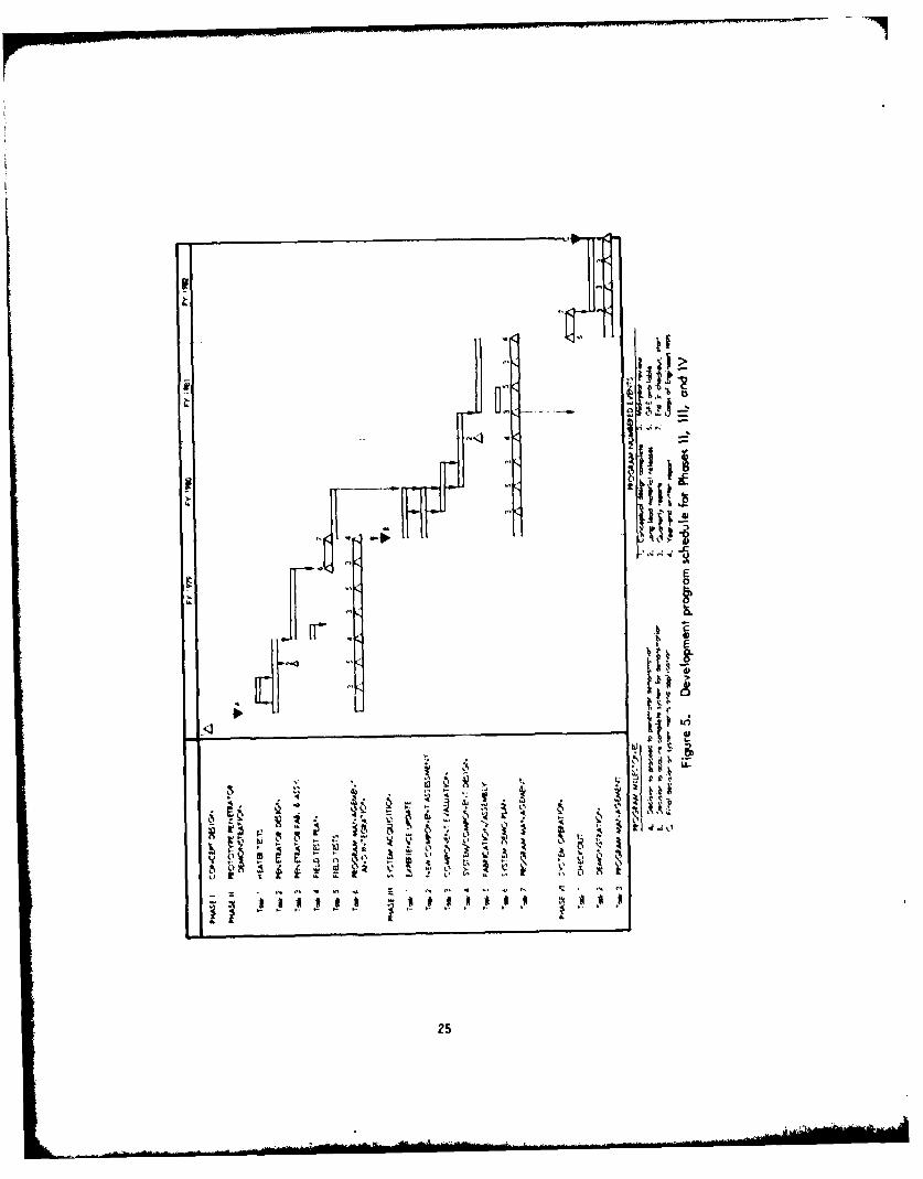
42. With the completion of the Phase I conceptual design study, the details of
subsequent phases were prepared consisting of three more phases spanning the next five
fiscal years. This development program is summarized by task in the schedule bar chart
of Figure 5.43. The objective of Phase II is to demonstrate a prototype penetratot in the
field. Operational performance can be evaluated through demonstration of penetration
rote, hole and core formation response to guidance through differential heating, starting,
stopping, and retraction evaluations. Six tasks are associated with this phase, heater tests,
penetrator design, penetratOt fabrication and assembly, fuel test plan, fuel test, and pro-
gram management and integration.
44. The objective of Phase Ill is the acquisition of a complete system for check-
out and field demonstration in Phase IV. This effort assumes a successful Phase 1l program
and the decision to proceed. Current plans envision the following seven tasks as appropriate
to Phase IlII experience update, new components assessment, component evaluation, system
and component design, fabrication and assembly, system demonstration plan, and program
management.
45. Phase IV is the test phase for the hardware required in Phase Ill. Its relation-
ship to the total program is shown in Figure 5, and it is expected to last one year. It will
consist of the following tasks: checkout, demonstration, and program management.
24
_____Jj: j
L _-
IV,-
25

PART 11 INTRODUCTION
Background
46. In December 1974 Westinghouse Advanced Energy Systems Division (AESD)
submitted an unsolicited proposal (BK-4038-0301) to the Corps of Engineers Waterways
Experiment Station (WES) to perform a "... conceptual design study of a small-diameter
long-range hole borer using a rock melting technique. " The device concept was termed
an Earth Melting Penetrator (EMP) and is an outgrowth of empirical proof-of-concept studies
conducted by Los Alamos Scientific Laboratory (LASL) in the IOs and early 19 70s on a
device LASL called the "Subterrene. " At about the same time, additional theoretical
studies were conducted by AESD (formerly Westinghouse Astronuclear Laboratory) to describe
the fundamental physical processes Involved In operation of an EMP. The proposed project
was the first phase of a long-term effort by AESD that could eventually result In a field-
tested prototype geoprospecting EMP. The three following phases of the effort can be
generally described by prototype demonstration, system acquisition and operations. The first
phase proposed was accepted in a joint agreement between the Corps of Engineers, Depart-
ment of Transportation, and National Science Foundation.
47. The earth melting system of producing holes has several features that are
different from normal methods of excavating and boring holes:
" A glass casing can be formed to line the bore holes or to caseand contain a core.
" The penetrator can be shaped to make a noncircular hale.
" The efficiency of the penetrator Increases with Increase of thein situ temperature.
* The expected long life of the heated bit can significantly reduce thenumber of times it must be removed to change penetrators.
* The penetrator does not need to rotate or reciprocate to make holes.
* In porous rock or soils, the melt con be consolidated to form a thickglass casing.
26
* In high density rocks and structures, the melt can be chilled by thecoolant and blown to the surface. Chilled melt-glass cuttings willnot decompose at the surface or contaminate surface water.
* In certain formations, the liquid melt can be used to "lithofracture"the formation, and the excess melt is forced into the fractures.
48. The unique features of EMP support a wide range of applications in addition
to survey of proposed tunnel routes with the remotely guided and self-propelled coring
penetrator proposed in this study. Some of these potential applications are:
* Retrieving glass encased cores from unconsolidated formations
0 Melting noncircular transportation tunnels and utilidors withfinished glass lining
0 Making drainage holes in archeological sites without damagingvibrations
* Punching precision holes in rock or soil for structural anchors
* Sinking glass-lined stabilized holes for foundation piles
0 Drilling holes for high explosive shot emplacement withoutdust
* Completing water wells with in-place, noncorrosive glass casings
* Making fluid and slurry conducting pipe lines
* Sinking large diameter shafts by melting a narrow peripheral kerf
* Drilling oblong holes to confine blasting to a desired cut-offline (curtain drilling)
* Implanting long, accurately profiled urban utility conduits throughcongested areas without surface disruption
0 Making ultradeep core holes for geophysical research
* Drilling in hot rock for geothermal energy or mining resourceexploitation
Study Objective
49. Based on the broad applications presented in the preceding section, the
Westinghouse Advanced Energy Systems Division proposed a design feasibility study of a
complete EMP drilling system. This study Is directed to advancing current drilling
27

technology. It is a reasonable next step since the feasibility of the process has been shown,
analytical performance functions are known, and available critical technology is sufficient
to minimize the development efforts. The overall project is envisioned in four phases in
order to reduce the exposure to risk. The first phase is the conceptual design and evaluation
ending in cost and development planning for the follow-on phases of the detailed design,
including an experimental demonstration, system acquisition and field evaluations.
50. The objectives of this study are fourfold:
e Conceptual design for a complete drilling system, includingpenetration, power supply, above ground facilities, cabling,and instrumentation
0 Determination of the limits and capabilities of the EMPperformance
0 Economic evaluation of the EMP
0 Formulation of a detailed development plan and cost estimatefor carry-on phases
Work Statements
51. The remainder of this report is organized according to contract task number.
Of the six tasks, five of them present deliverable items, with the sixth being Program
Management. The original tasks as proposed in BK-4038-0301 were reduced in scope, com-
mensurote with available funding. The contracted work statement includes:
Task I To develop integrated requirements for extra longreusable hales (the responsibility for this task wascompletely fulfilled by WES)
Task 2 To develop conceptual designs and alternatives basedon EMP techniques that have the potential for satisfyingthe requirements of Task I
Task 3 To perform a qualitative assessment of the relative tradesamong the concepts and parameters Identified in Task 2
Task 4 To provide visual, narrative and analytical description ofthe reference system concept
28

Task 5 To provide a logical development program For advancementof the reference system concept Into detailed design,development, fabrication and field testing
Task 6 To provide technical coordination and projectmanagement
29
PART IlU: REQUIREMENTS DEFINITION
by
James B. WorrinerWaterways Experiment Station
Background
52. Port III describes the requirements determined by WES for Corps of Engineers
usage of an EMP and the hole it will produce. Requirements stated herein were assembled
entirely by WES personnel from specifications and recommendations set forth by the Corps
Engineering Manuals, the American Society for Testing Materials, the International
Society of Rock Mechanics, Bureau of Mines reports, and Bureau of Reclamation reports.
Together, these requirements are Intended to represent the WES concept of the equipment
design features, the necessary characteristics of the EMP-created hole, the characteristics
of the EMP-recovered core, and the areas of further investigation into the lithologic
effects of tunneling a melted hole into a groundmass.
53. Several additions to and Increased emphasis on specific details in the
planned work were felt to be necessary. The additions and re-emphasis are, in all cases,
in the direction of expanding the flexibility of the tool and using the produced core and
hole properties as primary measures of the benefits accrued from EMP usage as compared to
the development casts and the use of conventional drilling methods. It will be noted that
a requirement for the ability to place vertical holes has been made to increase the flexi-
bility of the final EMP system. Except for the sensors providing penetrator guidance data,
no requirements have been formulated to include, as part of the EMP, equipment that will
log the hole as It is being made. Essentially no restrictions have been made on the degree
of fracturing of the groundmass during penetration. The emphasis on recovered core
quantities and the condition of that core has been increased. Emphasis on determining
the changes occurring in the penetrated groundmass has been increased, primarily in the
30
A - '4 --
areas of effects on geophysically logged properties. A device which could penetrate earth
and rock accurately over long distances would be of no real benefit if neither a representa-
tive testable core could be recovered nor meaningful logs could be made. The final productof the effort to develop a geoprospecting EMP Is not merely the physical system, although
it is a necessary milestone, but rather involves the ability to economically obtain complete
and meaningful geologic data along extra long subsurface paths.
54. The following paragraphs give quantitative description of the EMP require-
ments, subdivided into four categories of hole, liner, core/extrudite and groundmass.
Hole
Diameter specifications
55. The minimum hole diameter required for optimum use of in situ stress and
strength testing methods, for pressuremeter testing, and for use of small diameter geo-
physical logging tools is 7.6 cm. The minimum diameter quoted in Section 3. 1. 1 of the
proposal is 10. 2 cm. Both of these limits must be controlled by the core diameter require-
ments (Section 3. 1) since the Corps of Engineers considers the recovered core to be one of
the most Important products of the exploratory EMP. The minimum diameter of unmelted
core required is 5 cm. Thus, the minimum hole diameter will be 5 cm, plus the glass core
encapsulation annular thickness, plus the annular thickness of the EMP coring tip and melt
shaping surfaces. One of the tips fabricated by LASL was a universal extruding penetrator
having an OD of 11.4 cm and ID of 6.4 cm with a penetrator wall thickness of 2.5 cm.
These dimensions suggest a minimum hole diameter allowing 5 cm of core diameter and
1 cm of encapsulation is such that 5 + I + 1 + 2.5 + 2.5 = 12 cm.
56. The maximum hole diameter of 30 cm will allow passage of virtually all
available geophysical logging probes and yet is small enough to prevent the hole effect
from degrading the quality of the logs.
57. Allowable variations of hole diameter are plus 10 percent and minus
0 percent of the nominal diameter over 3 -meter intervals.
Hole length specifications
58. There is no effective restriction on minimum hole length save the cost and
effort of equipment setup and operation. Conventional drilling technology Is capable of
producing horizontal boreholes 50 to 100 meters or more in length, and for vertical boreholes In
31

lengths up to 150 or 200 meters which are quite economical. The EMP system design
is tentatively specified to be sufficiently economical In setup and operation such
that cas for a 200-meter horizontal melted hole will be comparable with costs for
conventional vertical drilling to explore a 200-meter horizontal right-of-way.
59. The maximum length of an exploratory EMP hole was defined in Section
3. 1. 1 of the proposal as 3 miles (approximately 5000 meters). This is about twice the
length of the Eisenhower Highway Tunnel in Colorado and about one-half the length of the
railroad relocation tunnel near Libby, Montana. Because a 5000-meter EMP hole could
have been melted from both portals of the latter example (a condition typical of virtually
all transportation tunnels), it is apparent that the proposed maximum length of the EMP
hole Is appropriate as a final requirement.
Location accuracy specifications
60. The location of the operating EMP tip should be known and controlled such
that there is at least a 90 percent probability of being within 5 meters radially from the
projected tunnel right-of-way centerline over the entire moximum range of 5000 meters.
Uncertainties In locating the EMP tip must be randomly distributed; that is, there should
be no systematic deviation in hole location such as might be caused by consistent dropping
of the tip in the gravity field.
61. Location data must originate at the tip and control applied from the portal
in the same time frame. Whether the control is applied directly to the EMP assembly and
tool string from the portal or Indirectly through signal transmission to the operating tip
assembly is Immaterial to Corps of Engineers usage, but it is expected that the former
type of method will prove to be more cost-effective.
Orientation (slant angle)
62. Military applications of the EMP as an exploratory tool fall within the
mission of the Corps of Engineers. The proposed length (5000 meters) and high degree of
location accuracy required of the EMP holes make the device attractive for use in site
examination for deep-seated facilities. In addition to the horizontal orientation of
tunnel right-of-way exploratory holes, one requirement associated with this application
stipulates that the EMP must be able to operate vertically within the same tolerances
32
stated elsewhere (diameter: Section 1. 1, length: Section 1.2, accuracy: Section 1.3,
penetration rate: Section 1.5). Intermediate hole slant angles between vertical and
horizontal are not required.
Required thrust/penetration ratio
63. The maximum thrust required to advance the EMP of approximately 90 kg
per cm of hole diameter will be commensurate with that available from conventional mobile
drilling units. For a minimum hole diameter of 12 cm, the requirement will be about 1100 kg.
For a maximum hole diameter of 30 cm, the required thrust will be about 2700 kg.
64. The most flexible type of EMP design is one which has a self-contained,
electrically driven thrusting assembly. This type is preferable to hydraulic units since
power can be obtained from the melting assembly. Because the associated cost of this
design detail may prevent its implementation, the major design effort should proceed in the
direction of thrusting by means of a stiff string of stems extending from the portal while,
at the same time, a preliminary subtask is undertaken to determine the feasibility of
electrically driven thrusters. Reverse thrusting will be necessary for tool extraction and
will be most easily accomplished if the primary thrusting utilizes a stiff stem. In any event,
even if thrusting and retraction is applied downhole, a backup retraction system operating
from the portal through the stem must be provided for emergency retrieval. The reverse
thrust (retraction) capability should be comparable in magnitude to the forward thrust
capability, that is, up to approximately 2700 kg tension. Penetration rates have been
shown to be dependent primarily on the applied thermal power and thrust force, secondarily
on porewater quantities, and minimally on material types to be penetrated. To avoid melting
tip replacement and assuming the post research conclusion of a 1000-hr tip life to be
achievable, then a 500 0-meter hole must be advanced at the rate of 5 meters per hour of
operation or greater. This rate of advancement is less than that of conventional equipment
in soft ground but greater by the same order of magnitude factor in very hard rock.
Required/available supporting activity
65. The EMP is assumed to be electrically powered and is required to derive
sufficient electric power for all operations from commercially available mobile generators.
These generators must be highway transportable either on a single chassis or a semi-trailer
truck.
33
33
66. The coolant used for rock melt cool-down control and EMP subassembly
cooling must be readily available in remote localities. Air would be best from a standpoint
of availability; water would be adequate if supplied at a high enough volume rote to prevent
steam generation or if the steam generated could be used to propel core and extrudite out
of the hole; and tanked nitrogen gas would be the most inconvenient of previously suggested
coolants from the standpoint of availability.
67. Helium has been used in the past as an inert anti-corrosion bath for the
heaters and Is satisfactory If the EMP tip assembly is sealed and does not require frequent
purging with the Inert gas. The reaction required for thrusting must be easily transportable.
Since the required thrusts should be modest, either dead weight or grouted rock or soil
anchors can be used for vertical and horizontal hles.
68. All subsystems associated with the EMP and its operation must be
transportable by trucks. Subassemblies such as cable and stem sections should be of sizes
and weights that can be carried by several men or at least by a light duty truck-mountedhoist.
69. The control and operating consoles should be capable of real-time
representation of tip location relative to its nominal projected path, should allow the
operator to maintain manual control of all phases of the penetration operation, should
continuously record both location data and control commands, and should provide a
single-command Initiation of the emergency retraction sequence of operations to prevent
loss of the tool or danger to the workers. All system electrical connections must be
fall-safe protected for safety during stem section attachment. Protective eqtiipment
must be provided for the possibility of Inadvertent steam or other volatile release from
the portal area under high pressure.
Uses of EMP created hales
70. The following Is a list, In order of decreasing projected importance
to applied civil engineering, of probable applications for EMP-created holes.
a. Core sampIing recovery. Despite the advent and increasingapplication of In situ mechanical and geophysical measurementtechniques, the core recovered from underground explorationremains the mainstay of geologic and rock mechanics characteriza-tion. Recovered core must be disturbed as little as possible from
34
its in situ condition, must be available for direct examination forlithologic and structural characteristics, and must be of anappropriate size to allow meaningful extrapolation of laboratorytest interpretations to the subsurface environment.
b. Gophysical Iolnq. The EMP-creoted hole must provide anenvironment conducive to the application and accurate interpreta-tion of various geophysical logging methods. The glass liner andthermal alterations to the groundmass peculiar to a melted holemust be examined in minute detail so that their effects on geo-physical logs can be minimized or incorporated into the datainterpretation. This application is second in importance onlyto direct examination of recovered core and may, in the nearfuture, surpass core testing in the opinion of design engineers.
c. echonical/fluid tstin. Included within this category ofapplications ore on situ elastic property measurements such ashydofracturing stress measurements, borehole jack strength andstress measurements, and in situ fluid permeability measurements.The deformation properties and structural integrity of the linerore of greatest importance to this category of applications.
d. Conduits for utilities. These applications make direct use of theEMP-created hale as a final product rather than as a preliminarystep in large-scale entries into the earth. The most Importantcharacteristics of the hole in this category of applications willbe length, diameter, and cost-effectiveness.
e. Fluid transfer. This category is closely related to the above with- the ad;erequirement for liner integrity. Specific applications
are access holes to geothermal energy sources or recovery ofand transportation of geologic fluids such as water and hydro-carbons.
Liner
Physico-chemical nature of liner material
71. The nature of the material comprising the gloss liner remaining after
EMP penetration of the various modeled geoloqic materials is of importance to the correct
usage and interpretation of geophysical logs in the hole. Specific areas of required
theoretical research ore the electrical properties, the nuclear radiation properties, and the
vulnerability of the liner material to chemical alteration. The electrical properties of
interest are resistivity and dielectric constant. Nuclear radiation properties are inherent
35

gamma and neutron spectra and capture cross sections of thermal and epithermal neutrons.
Chemical alterations of the liner material in aerial, aqueous, and mineralized geothermal
fluid environments must be researched for applications to fluid transport. Proof of EMP
feasibility and concomitant design and fabrication will result in requirements for empirical
verification of the theoretical representations of liner properties.
Structural integrity requirements
72. The required structural integrity of the EMP hole liner will vary according
to the application. The shortest life required before blockage is that for core recovery
only. The life span would only be the time required for hole creation and tool recovery,
on the order of 1000 hr. Insertion and recovery of geophysical and/or mechanical testing
tools effectively doubles the required life span to 1000 hr after hole completion. In the
latter instance, the high probability of hole destruction by the action of mechanical testing
must be considered. The longest required life span is in applications such as conduit
passages or fluid transport and is on the order of magnitude of 100,000 hr or 100 times the
minimum life span. For such long life spans, the use of hole reinforcement or placed liners
seems at first glance to be feasible but is beyond the scope of the current study.
73. Maximum overburden thicknesses acting on the liner structure are assumed
to be 3000 meters in blocky and seamy (Terzaghi's definition) rock and 100 meters in soil
type materials (UNCON). Minimum overburden thickness is 10 meters in all material.
In the calculations involving the minimum overburden thickness, localized surface loadings
ranging from 1000 to 150,000 kilograms per square meter must be included.
Elastic properties of the liner
74. Elastic properties of the liner materials resulting from the modeled
geologic materials must be known for input into structural integrity studies and for
determination of the liner's effect on geophysical acoustic logging and in situ mechanical
testing data. Desired acoustic properties include compressive and shear wave velocities,
wave amplitude attenuation parameters, and the degree of attachment of the liner to
the ground mass in terms of acoustic wave impedance mismatching. Other elastic
properties necessary are the various deformation moduli and Poisson's ratios.
36
Fluid flow properties of liner
75. The Intact and crack permeabilitles of EMP hole glass liners are required
for determination of EMP applicability to in situ groundmass permeability testing and to
fluid transportation conduits. In the event that liner permeabilities are too low for valid
groundmass hydrologic testing in the EMP hole, the measured "leakiness" of the liner can
be used to determine the degree of cracking in the liner itself for input Into structural
stability of the EMP hole.
Liner effects on geophysical log data
76. To properly use geophysical logs in EMP holes, the effect of the glass
liner on the measured physical phenomena must be known. It is anticipated that minimal
and correctable effects will be noted in acoustic logging. Because much electrical logging
relies on current conduction through ionic aqueous solutions, the degree of liner cracking
and, thus, communication with the groundmass will greatly affect these frequently used
logging methods. Electro-magnetic radiation and induction electrical logs are expected
to show little degradation resulting from the glass liner. Likewise, nuclear radiation logs
are not expected to be degraded. These hypotheses must, however, be verified.
Core/Extrudite
Core diameter requirements77. Based on standards for rock testing established by the Corps of Engineers,
American Society for Testing Materials, and International Society of Rock Mechanics,
the minimum diameter of rock core for laboratory testing is NX-sized or approximately
5.4 cm. Corps of Engineers soil testing procedures recommended the following minimum
diameters:
Unit weight 3 in. (7.6 cm)
Permeability 3 in. (7.6 cm)
Consolidation 5 in. (12. 7 cm)
Triaxial compression 5 in. (12. 7 cm)
Unconfined compression 3 in. (7.6 cm)
Direct shear 5 in. (12.7 cm)
37
78. However, NX-sized soil core samples are commonly, if not routinely,
tested. Therefore, 5.4 cm is the minimum required diameter of the unmelted portion of
core to be recovered by the EMP. The largest core diameter recommended by the Corps
is 6 in. (15.2 cm), primarily because of capacity limitations inherent to all except
specially constructed test equipment. The maximum unmelted core diameter limitation is
thus 15 cm.
79. Limitations on minimum and maximum encapsulation are not fixed, although
the encapsulation must be adequate to allow recovery of intact specimens of granular,
noncohesive soil (UNCON).
Thermal gradient restrictions in core
80. Thermal conditions to which the recovered core is subjected must be
investigated for the entire period from approach of the EMP tip through passage to the cool
ambient temperature recovery. Maximum temperature levels at radii from the axis out to
the melted portion or encapsulation must be determined, the time intervals for temperatures
of various proposed penetration rates established, and the probable mineralogic and
hydrologic effects within the core caused by these temperatures estimated for each of the
geologic material models.
Usable lengths of core segments
81. Laboratory testing standards require minimum core sample lengths of
two times the test specimen diameter. Therefore, he minimum acceptable length of
recovered segments from the EMP in any geologic material will be 2-1/2 times the
diameter of the unmelted internal portion of the recovered core.
Recovery of core/extrdite
82. The core is to be recovered in a manner comparable to conventional
wireline techniques in that the core recovery will not require pulling the entire string
of stem and melter assemblies from the hole. Pneumatic propulsion of the core to the
portal is acceptable.
83. The minimum proportion of testable core, that is the total accumulated
length of core segments greater than 2-1/2 times the unmelted internal portion is to be
50 percent of the total length of the hole. The total accumulated length of recovered
38
=,.. .. . . . . .- - ] I P' :'[':A ,

core Including core segments shorter than 2-1/2 times the unmelted portion Is to be
90 percent of the total length of the hole. These requirements are for all modeled
geologic materials.
84. These recovery proportion requirements are undoubtedly demanding but
are necessary both because of the current importance of core examination for reliable
subsurface condition interpretation and because the core segments lost in recovery are
most frequently from the precise intervals most critical for the design and construction
of economical and stable tunnels. While the ideal capability may be unattainable, it
would approach 100 percent core recovery.
Groundmass
Induced fracturing/surface upheaval
85. Because of the large ratio between the minimum ground cover thickness
and the EMP hole diameter, surficial deformation is anticipated to be negligible or
nonexistent.
86. The degree of melt pressure induced fracturing will not be restricted
for this design study although analyses and, eventually, empirical studies will be
required to define the relationships between applied thrust, melt pressure, and the
quantitative description of the resultant earth and rock fractures for the EMP design.
Thermal gradients in groundmass
87. Amplified analyses of the thermal gradients and time variations of these
gradients in the groundmass surrounding the glass liner are required for all modeled
geolkgic materials. These analyses will be applied to the determination of the
physicko-chemical alterations to the groundmass lithology due to the passage of the EMP.
The affects of these alterations on the responses of the various geophysical logging
methods and mechanical and hydrologic test methods will be determined. Some of
the specific phenomena to be addressed are electrical resistivity and dielectric
constant changes, changes in the groundmass gamma and neutron emitted spectra,
changes in thermal and epithermal neutron capture cross sections, changes In
39
remanent magnetism and permitivity, changes in elastic deformation parameters pertaining
both to acoustic logging and in situ mechanical testing, and the temporary and permanent
alteration to the groundmass hydrologic conditions. These analyses are to be considered
of paramount importance to the exploratory applications of the EMP and the benefits
derived therefrom.
Materials to be penetrated
88. The models of geologic materials utilized in the earlier DOT study (Reference 1)
are adequate, with the exception of UNCON. That model should be altered, or Its applica-
tion should be firther detailed, to Include two soil fractions that are quite common and
one strotigraphic configuration that is nearly universal. The UNCON model should
include a clay mineral fraction to range from that applied In SOSED up to 100 percent
by weight. Variations of UNCON and SOSED, especially the former, should include an
organic fraction of I to 5 percent by weight. Earlier studies make no mention of the
response of an organic fraction in the melt, solidified liner, or neighboring heated
groundmass. While the majority of organic soils lie at shallow depth, less than the
specified minimum ground cover thickness, there Is significant occurrence of this type
of soil at depths below 10 meters in the form of marine clays, cyclothem sedimentary
sequences, and valley alluvia. The variation of stratigraphic configuration that must be
addressed is a layer or lens several meters thick of nearly pure quartz sand located
within UNCON or SOSED. This stratigraphic configuration is almost universnl in
valley alluvium and fairly common in glacial deposits. Because of the very high melting
temperatures required to penetrate pure quartz sand, it would be unfortunate to halt
EMP advancement in a given long exploratory hole because of a relatively short length
of path through a point bar or outwash channel deposit. The possibility of melt flow from
heterogenous lithologles acting as a natural flux for pure quartz sand layers of finite
dimensions should be investigated quantitatively.
89. The existence of effective flux additives and the feasibility of their
application around the melting tip must be determined as an Improvement to the
EMP's efficiency.
40
4k

PART IV: CONCEPTUAL DESIGNS
System Performance Analysis
90. Prior to initiating design work, a parametric study on size and performance
variables was completed to develop preliminary evaluations of system requirements. These
have been subdivided into geometry, power and thrust, and groundmass effects in an effort
to parallel the preceding section.
Geomet
91. Within the diametral constraints of OD < 300 mm and ID > 50 mm, melt
power will be minimized for the smallest size penetrator but downhole equipment packaging
becomes more difficult. For the parametric study, It was estimated that 200 mm is the
smallest hole diameter that could conceivably accommodate equipment such as guidance
electronics. Therefore, when calculations could not be performed nondimensionally, two
diameters, 200 and 300 mm (8 and 12 in. ), were selected as the basis for calculations.
92. The required liner thickness to support the overburden can be calculated as
a function of depth from surface and type of overburden. The maximum required depth
of 100 m was selected to be met for all situations. Techniques and assumptions of the
calculations for liner thickness are contained in Reference 1. Five geologic property models
will be used throughout this report. Their composition and thermomechanical property
values are also derived In Reference 1.
93. Without considering any surface loading, calculations were performed for
the UNCON and MASIG models, the least and most dense, respectively.
94. For the UNCON geologic model, the condition of restrained lateral
deformation was selected for calculation. It assumes the earth settlement about the glass
liner Is such that It returns to the overburden condition which existed prior to hole formation
and that the overburden has no tensile strength. The equation for maximum permissible
depth Is
41
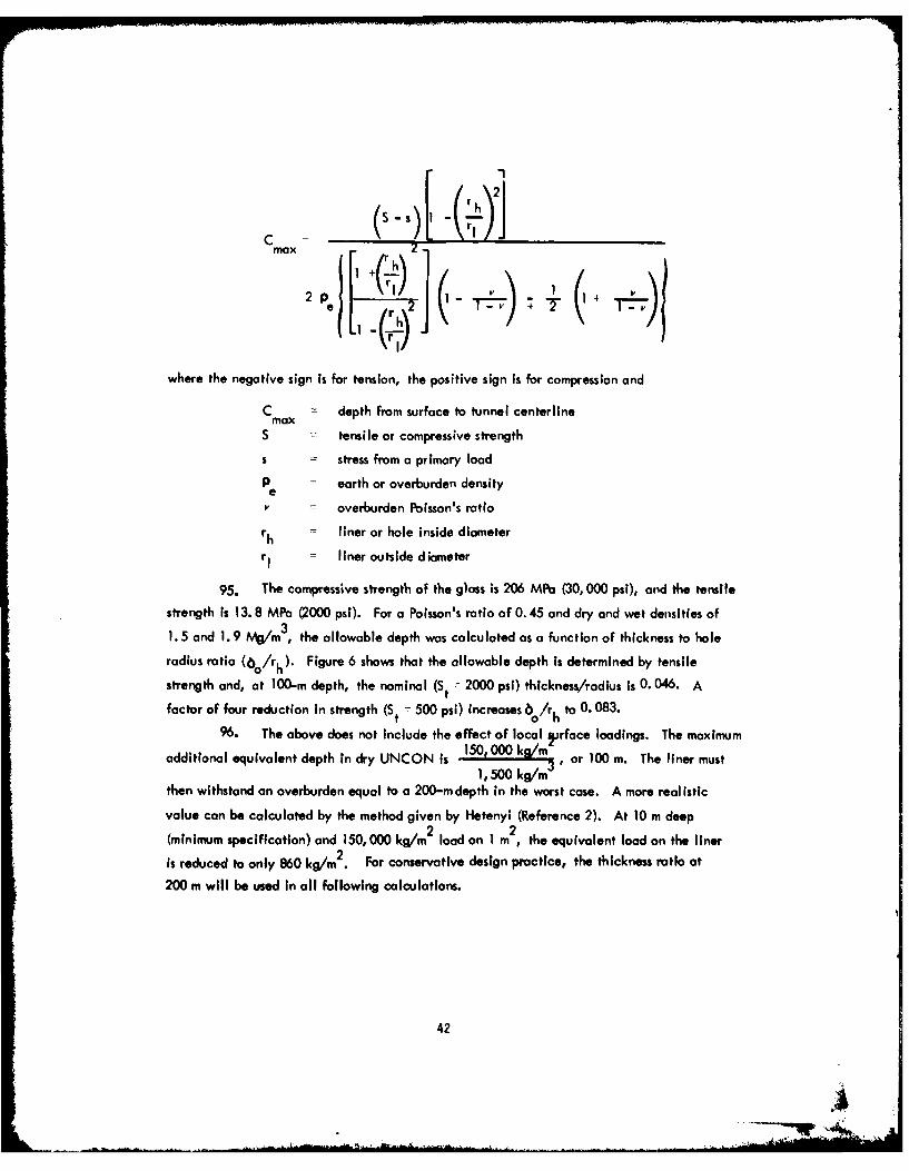
max
.1 -k l)-11
where the negative sign is for tension, the positive sign is for compression and
C -- depth from surface to tunnel centerlinemax
S tensile or compressive strength
s = stress from a primary load
P = earth or overburden densitye
V = overburden Poisson's ratio
rh liner or hole inside diameter
rI -- liner outside diameter
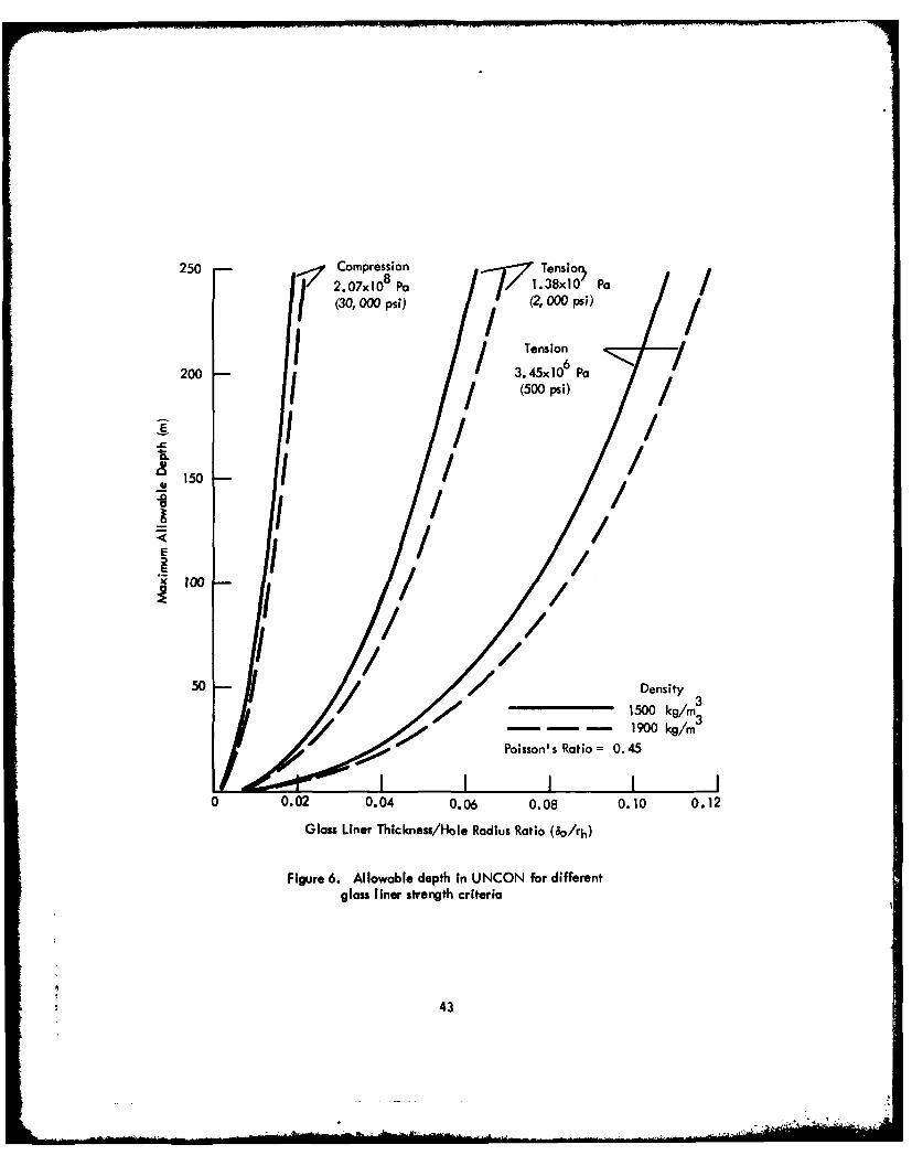
95. The compressive strength of the glass is 206 MPa (30, 000 psi), and the tensile
strength is 13. 8 MPa (2000 psi). For a Poisson's ratio of 0.45 and dry and wet densities of
1. 5 and 1.9 /m 3 , the allowable depth was calculated as a function of thickness to hole
radius ratio (6o/rh). Figure 6 shows that the allowable depth Is determined by tensile
strength and, at 100-m depth, the nominal (St - 2000 psi) thickness/radius is 0. 046. A
factor of four reduction in strength (St = 500 psi) Increases 6o/rh to 0. 083.
%. The above does not Include the effect of local Jrface loadings. The maximum
additional equivalent depth in dry UNCON is 1500 kg/m or 100 m. The liner must1, 500 lkg/m 3
then withstand an overburden equal to a 200-m depth in the worst case. A more realistic
value can be calculated by the method given by Hetenyi (Reference 2). At 10 m deep
(minimum specification) and 150,000 kg/m load on I m , the equivalent load on the liner2
is reduced to only 860 kg/m . For conservative design practice, the thickness ratio at
200 m will be used in all following calculations.
42
250"7 2.07xlO Pb 7Y7 .38XO~ PaC/ (30,O000psi) (2,000ps;)
I I Tension/200 - 3.45xl 0 Pa
I / (500 ps)/
150 /IE
2EI
50 -_______ Density3
1500 kg/n 3- - - 1900 kg/rn
Poisson' s Ratio= 0. 45
0 0.02 0.04 0.06 0.08 0.10 0.12
Glass Liner Thickness/Hole Radius Ratio (60/rh)
Figure 6. Allowable depth In UNCON for differentglass liner strength criteria
43
97. Similar analyses were performed for SOSED and MASIG overburdens which
are in the order of decreasing Poisson's ratio. In these cases, the assumption of zero tensile
strength of the overburden is too severe, producing the requirement of thickness/rodius ratio
of up to 0. 3 at a 200-m depth. An equivalent tensile strength of "blocky and seamy" over-
burden at a 3000-m depth is required to evaluate liner thickness on a realistic basis. This
is true for the scale of the tunnel relative to the depth in a competent formation. For a
full-size tunnel, this assumption would not be valid. However, for 300-mm dimensions,
the overburden does possess some tensile strength. Thus, the UNCON model becomes the
limiting case establishing the liner thickness requirement.
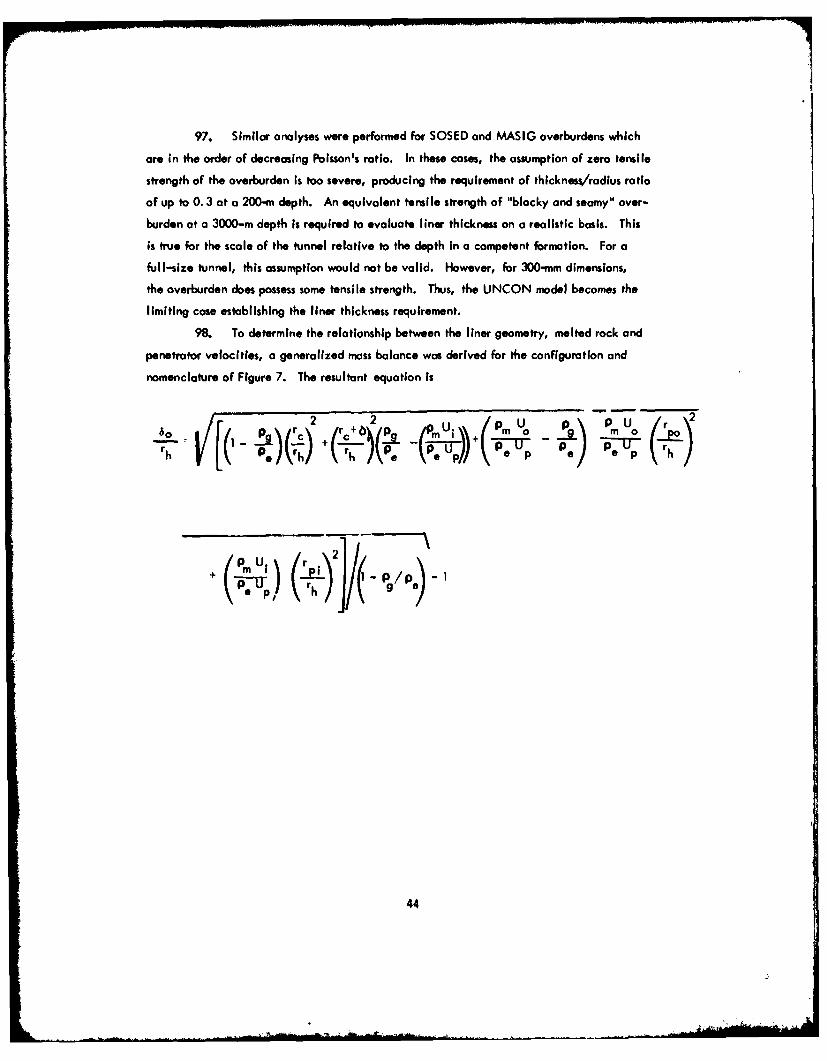
98. To determine the relationship between the liner geometry, melted rock and
penetrator velocities, a generalized mass balance was derived for the configuration and
nomenclature of Figure 7. The resultant equation is
2 r /pU mp 0
h )Iel rh) + hAe + mo.."iD-Ir ieI-op irh
44
- U
U.
UN DISTURB EDCORE
Figure 7. Portetrotor schematic
45
wherehore liner thickness
p - glass liner density
P - melt density
99. A moss balance parametric study on dimensions, geologic model, penetration
velocity and extrudite velocity was made to size the device consistent with its requirements.
The results of this study indicated that a ratio of extrudite to penetrator velocity of approxi-
mately 20 gives the desired Iiner thickness within the range ofdimensions and model densities.
lower and Thrust
100. Using the energy equations and model properties developed in Reference 1,
the heater power and penetrator surface temperatures were calculated for two diameters and
five geologic models as a function of penetrator velocity. The power equation is:
keff Am (Tm - Tq + 2 (rh + b)
S pU fC(T-T)+ C (Tmax - T,)+m e Up mC T mo
whereq = heater power
C = mean circumference of melt/earth Interface
= -- effective heat penetration depth
C - earth specific heatpT m- melt temperature
k =ff effective thermal conductivity
A = surface area of melt/earth interfacem
T= - ambient earth temperature
46
+ . . + :
S - cross-sectional area of meltm
C - specific heat of meltm
T penetrator surface temperaturemaxA - latent heat of fusion
101. The first two terms represent dynamic (moving) and static heat losses to the
unmelted rock. Figures 8 and 9 show the power requirements for 200-and 300-mm diameter
holes for velocities up to 1.4 mm/sec (5 m/hr). Thus, the maximum power of 1050 kW is
for CALCI. Heaters are to be sized to deliver up to 1200 kW to meet the requirement of
5 nmr in any media. Figure 10 shows the amount of power required to melt and also the
power lost to the surroundings in the process, as reflected by the previous equation for the
CALCI model. If there were no requirement to penetrate CALCI, power could be reduced
by nearly 25 percent to MASIG.
102. The above predictions on heater power are based on LASL test data and are
considered reasonably accurate. The prediction of surface temperature by a simple analysis
is much more difficult. The thermal conductivity of liquid rock (keff) is an unknown
quantity and significantly increases uncertainty in analysis, as indicated in Reference 3.
Several new attempts at liquid conductivity were investigated but all gave low values.
One example, shown in Figure I I for MASIG, is extrapolated from the basalt study of
Reference 4 and the mantle conductivity calculations of Reference 5. However, the use
of the liquid model with the heat transfer model of Reference I does not correlate with
LASL measured penetrator surface temperatures in basalt. The surface temperature equation
used to calculate surface temperature curves as shown in Figures 12 and 13 is:
Tmax m m q q
where W
q melt superheatS -constant in liquid thermal conductivity equation
47
00
C
00
EE
ui LU
LU LU
o ou
10 C10
C4O48
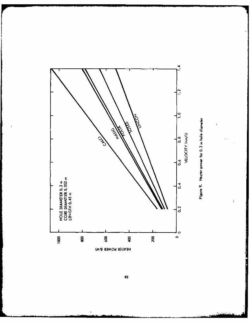
0%4
'0
Uj 4-
-i lw
0E
86664
(MV M~d ~iV3
UJILJ49
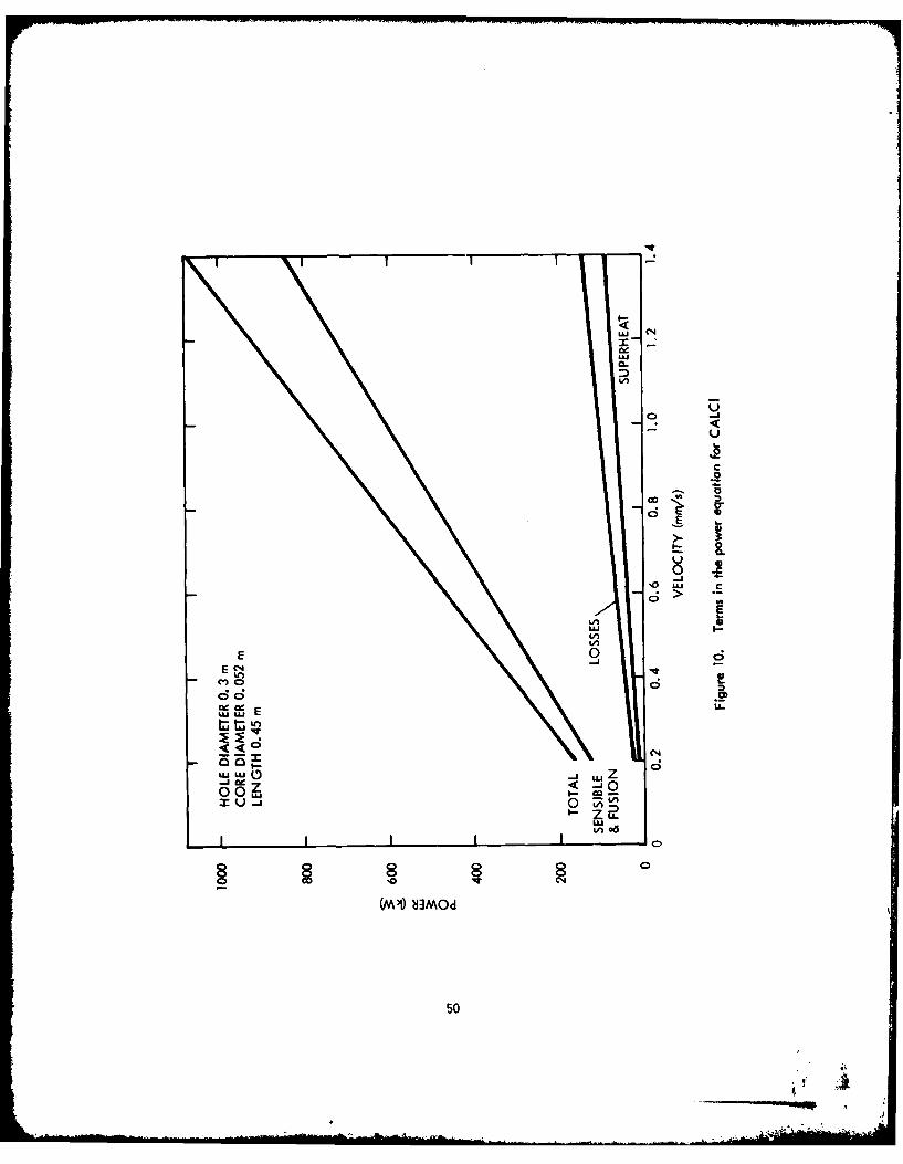
LuJ
k-
CO
0 L
LM Itn
E %
cel'Ui El :LC50
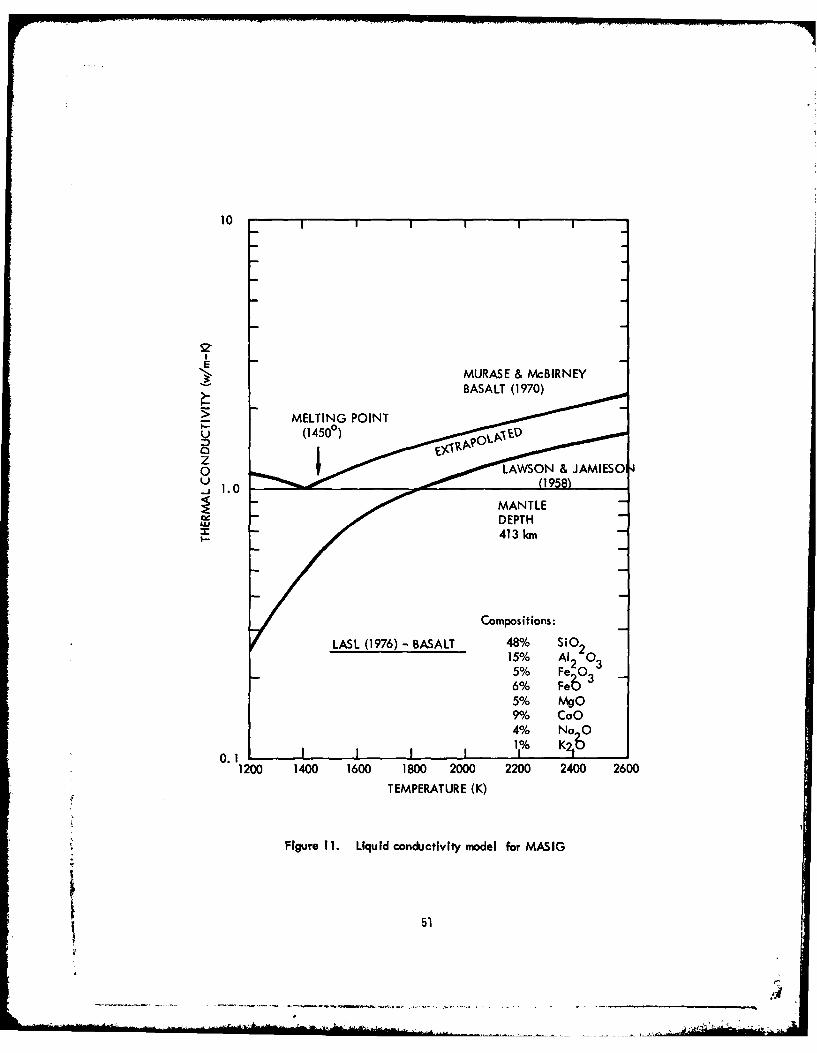
10
E
> MELTING POINT
0 10z
1.0
Compositions:
KLASI (1976) - BASALT 48% o215% Al2 0 35% FeO06% Fe 3
5% mgo
4% Nao
0. 1 K1200 1400 1600 1800 2000 2200 2400 2600
TEMPERATURE (K)
Figure 11. Liquid conduictivity model for MASIG
51
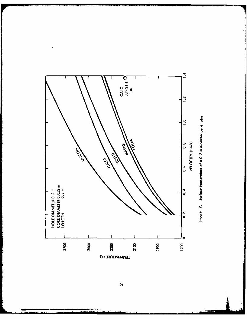
- E-
UOE
0
oE E0~~ oI-)
-1- - ~ 04o O
E 84(n O~
UJIA900N
ad ccV
6i ad-
0o 0 -
52
n
UJu
0
10
E- N
Im flue
uiu
U C0
ooz 0 - AJUu 0Q
53

103. From these curves, it becomes obvious that the surface temperature is the
velocity limiting parameter in the system. A single point calculation was made for the
CALCI model at an increased L/D of 5 rather than 1.5 as on the curves. This value yields
an increased surface area for approximately the same power, although increased surface
area slightly increases losses and reduces the temperature by nearly 400 K. An extended
surface configuration (fins) can be used to reduce the temperature and is presented in the
discussion of design selection.
104. Refractory metals such as tungsten, molybdenum, tantalum, and niobium
and a few carbide, nitride, and boride compounds are the only practical candidate materials
for 2300°C application. There is severe corrosion by molten earth at higher temperatures.
Also, the silicide coatings developed to prevent the elevated temperature corrosion
of refractory metals would be readily dissolved by molten earth. If the temperature calcula-
tions are reasonably accurate, it will be difficult to meet all the requirements of tip
lifetime and penetrator velocity In any media.
105. The applied thrust load calculation, neglecting stem drag, is based on an
equation in Reference 1.
F 2(r2p°'r2)P C + 3 p M U r 2 2 r p U cotO=w~ pr[P +PO + 2po imUp 1PO s emax 2gc b2 sing gcb2
i 1oupB3 [4 rs2+ '8 4r In ( - -3rs 2 -r (r- r
4wr Op c U L+ , o. p c
gc bo
where
F = applied thrust load
lim = melt viscosity0 = half angle of the penetrator head
P = temperature coefficient of viscosityB = constant of temperature distribution
54
ijc = viscosity at cooldown transition temperature
L = length of cooldown sectionc
gc = gravitational constant
106. Results for three of the five models are shown In Figure 14. Excluding
stem crop, a maximum force of 10 5N (23,000 Ib) is required.
Groundmss
107. Effects of the penetrator on the hole and its use were emphasized by the
requirements. The first Is the effect of the deposited heat on properties of the unmelted
earth and the second is this effect on the validity of present logging measurements.
Heat Wave Penetration
108. A transient analysis was performed to estimate the extent of temperature
perturbations in the earth surrounding the path of the EMP. Of main Interest were the
radial distances from the EMP at which earth temperature changes will be caused by the
penetrator and the time periods required. Considerations such as these are Important
in situations involving earth melting in the vicinity of buried cables and power lines,
water lines, etc. The earth heatup calculations were also used to provide estimates of
the heat transfer rate between the cylindrical surface of the EMP and the surrounding
earth, to correlate with previous simple analytical expressions.
109. The analysis applied an earth heat transfer model In the form of a circular
disk, composed of concentric, ring-shaped elements or nodes. As shown in Figure 15, the
earth material surrounding the penetrator was represented by 58 nodes. W)Jring the computer
simulation of the problem, each node was assigned an initial temperature, material
thermal properties and values of volume, cross-sectional area and heat conduction length.
The 5. 0-in. radius of the penetrator/earth interface was established by the diameter of the
penetrator, which was assumed to be 10 In.
110. The earth heat transfer model is one-dimensional In the radial direction.
The one-dimensional feature provides the analysis with some conservatism during heatup
and cooldown since heat dissipation cannot occur parallel to the penetrator axis. The
model also introduces some nonconservative effects since the nodes cannot preheat prior to
the arrival of the penetrator or continue to heat after the penetrator has passed. While these
55
E
50
0 .!
Ix I
I I I I I I I II I I I I , 1 .
56~
-~ SURFACE I
C! 58
57
*56 28 in.
F.3 2*31
M 302 9
PEN ETRATOR/EARTH 2-INTERFACE DURING * IHEATUP. LINER SURFACDURING COOLDOWN
EMP CENTERLINE AND PATH 5.0 in.
Figure 15. Earth heat transfer model
57
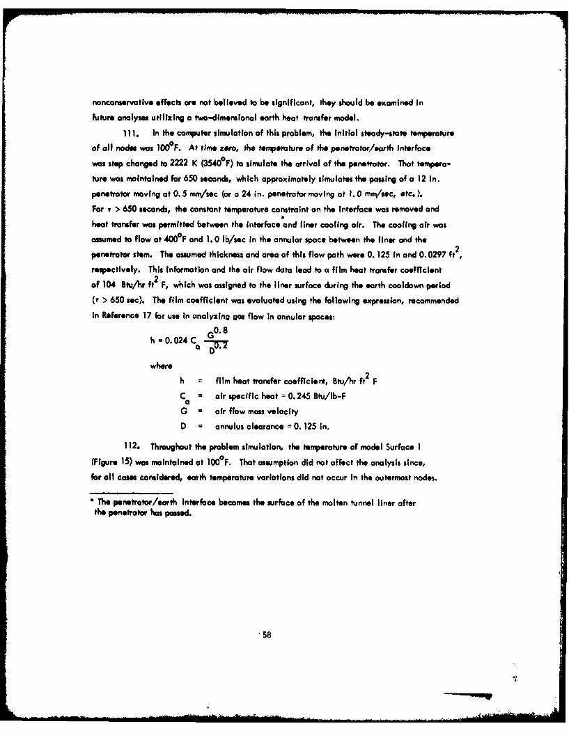
nonconservative effects are not believed to be significant, they should be examined in
future analyses utilizing a two-dimensional earth heat transfer model.
111. In the computer simulation of this problem, the Initial steady-state temperature
of all nodes was 0 0OF. At time zero, the temperature of the penetrator/earth interface
was step changed to 2222 K (3540°F) to simulate the arrival of the penetrator. That tempera-
ture was maintained for 650 seconds, which approximately simulates the passing of a 12 in.
penetrotor moving at 0. 5 mn/sec (or a 24 in. penetrator moving at 1.0 mm/sec, etc. ).
For T > 650 seconds, the constant temperature constraint on the Interface was removed and
heat transfer was permitted between the interface and liner cooling air. The cooling air was
assumed to flow at 400°F and 1.0 lb/sec in the annular space between the liner and the2penetrator stem. The assumed thickness and area of this flow path were 0. 125 in and 0. 0297 ft
respectively. This Information and the air flow data lead to a film heat transfer coefficient
of 104 Btu/hr ft2 F, which was assigned to the liner surface during the earth cooldown period
(r > 650 sec). The film coefficient was evaluated using the following expression, recommended
in Reference 17 for use in analyzing gas flow in annular spaces:
h = 0.024C 0"
where
h = film heat transfer coefficiert, Btu/hr ft2 F
C = air specific heat = 0. 245 Btu/Ib-Fa
G = air flow mass velocity
D = annulus clearance = 0. 125 in.
112. Throughout the problem simulation, the temperature of model Surface 1
(Figure 15) was maintained at 1000F. That assumption did not affect the analysis since,
for all cases considered, earth temperature variations did not occur in the outermost nodes.
* The penetrator/earth Interface becomes the surface of the molten tunnel liner afterthe penetrator has passed.
58
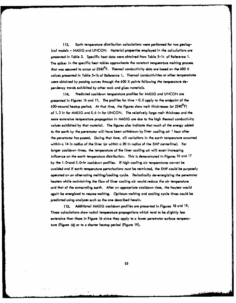
113. Earth temperature distribution calculations were performed for two geolog-
ical models - MASIG and UNCON. Material properties employed in the calculations are
presented in Table 3. Specific heat data were obtained from Table 5-ic of Reference 1.
The spikes in the specific heat tables approximate the constant temperature melting process
that was assumed to occur at 2240F. Thermal conductivity data are based on the 600 K
values presented in Table 5-lb of Reference 1. Thermal conductivitles at other temperatures
were obtained by passing curves through the 600 K points following the temperature de-
pendency trends exhibited by other rock and glass materials.
114. Predicted cooldown temperature profiles for MASIG and UNCON are
presented In Figures 16 and 17. The profiles for time = 0. 0 apply to the endpoint of the
650-second heatup period. At that time, the figures show melt thicknesses (at 2240°F)
of 1.3 in for MASIG and 0.6 in for UNCON. The relatively large melt thickness and the
more extensive temperature propagation in MASIG are due to the high thermal conductivity
values exhibited by that material. The figures also Indicate that much of the energy added
to the earth by the ponetrator will have been withdrawn by liner cooling air 1 hour after
the penetrator has passed. During that time, all variations in the earth temperature occurred
within a 14 in radius of the liner (or within a 20 in radius of the EMP centerline). For
longer cooldown times, the temperature of the liner cooling air will exert increasing
influence on the earth temperature distribution. This is demonstrated in Figures 16 and 17
by the 1.0-and 5.0-hr cooldown profiles. If high cooling air temperatures cannot be
avoided and if earth temperature perturbations must be restricted, the EMP could be purposely
operated on an alternating melting/cooling cycle. Periodically dc-energizing the penetrator
heaters while maintaining the flow of liner cooling air would reduce the air temperature
and that of the surrounding earth. After an appropriate cooldown time, the heaters would
again be energized to resume melting. Optimum melting and cooling cycle times could be
predicted using analyses such as the one described herein.
115. Additional MASIG cooldown profiles are presented in Figures 18 and 19.
Those calculations show radial temperature propagations which tend to be slightly less
extensive than those in Figure 16 since they apply to a lower penetrator surface tempera-
ture (Figure 18) or to a shorter heatup period (Figure 19).
59
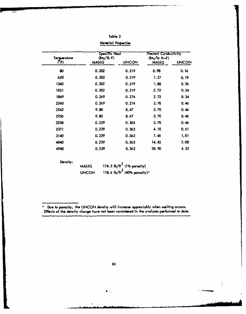
Table 3
Material Iropertie
Specific Heat Thermal ConductivityTenperature (Bht/lb F) (Btu/A ft-F)(F) MASIG UNCON MASIG UNCON
80 0.302 0.319 0.98 0.16
620 0.302 0.319 1.27 0.19
1340 0.302 0.319 1.88 0.26
1831 0.302 0.319 2.72 0.34
1849 0.269 0.274 2.72 0.34
2240 0.269 0.274 3.70 0.46
2242 9.80 8.47 3.70 0.46
2256 9.80 8.47 3.70 0.46
2258 0.239 0.363 3.70 0.46
2371 0.239 0.363 4.10 0.51
3140 0.239 0.363 7.46 1.01
4040 0.239 0.363 14.45 2.08
4940 0.239 0.363 28.90 4.33
Density:3MASIG 174.5 lb/ft3 (1% porosity)
UNCON 118.6 lb/ft3 (40% porosity)*
D Due to porosity, the UNCON density will increase appreciably when melting occurs.Effects of the density change have not been considered in the analyses performed to date.
60
-
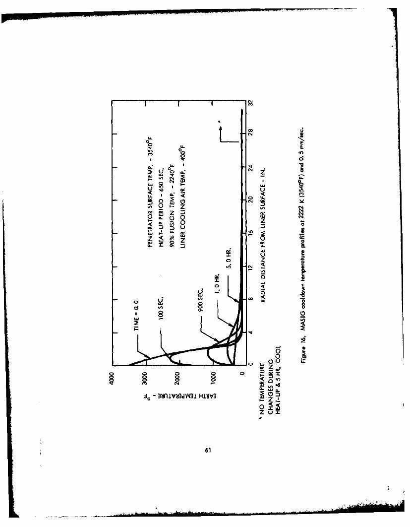
I I C.)
LLLL.L
LOL
~0 CN Y
LU n%
0
QL!U
z 21 C
LL
LUJ SL l
In S
ad
i-
z0u
610

LL. C14
0 0LLU
LL. 0 a
LU LU 4 vI.- If, (N Lu
4A -4 L
<I,
D LUJ 0
01 Z~ -i Ja 40
1.- 50 LL0
00wI 0
L w uS
02
-o 3SflYvS3dW~i HISV3
62
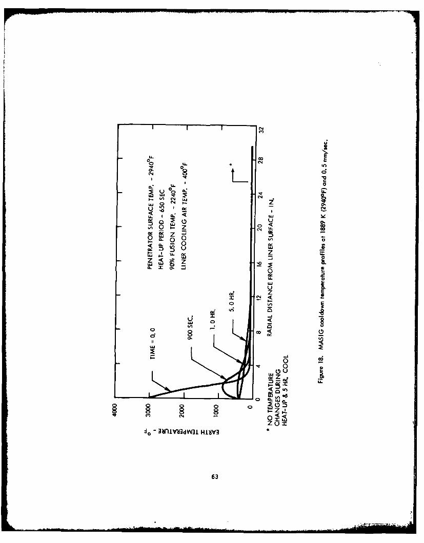
0 0N~
V0
U-
CNN
-Ivi 00.
C4 U
0 -J 0 vCLI
U.
IN0 ILAto8
Lu -
0 0.
D UU
0
Zum-o 3MiliVSadw H1VV3
63
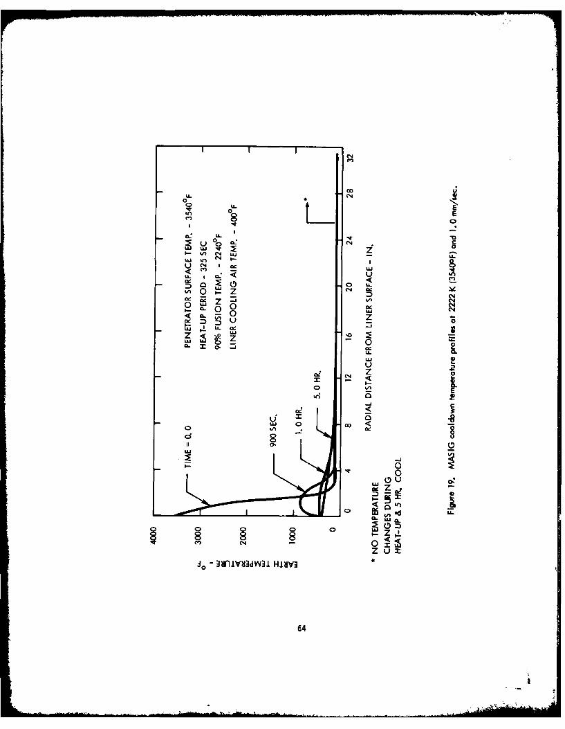
ILL
on 0
00 C4cLUvz z1^ UI 4 (N L .
U ccI LLL *C- U
DU o(N
0 0 wUJJ (o
0~
LUUL( z
Z- 0
CL 0' -8c
OUU
Iz-
C.,' -
ox:u- 3~iVd~431H.L0V
04
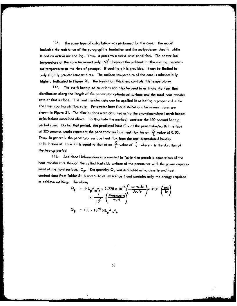
116. The same type of calculation was performed for the core. The model
included the resistance of the pyrographite Insulation and the molybdenum sheath, while
it hod no active air cooling. Thus, it presents a worst-case condition. The centerline
temperature of the core increased only 150°F beyond the ambient for the nominal penetra-
tar temperature at the time of passage. If cooling air is provided, it can be limited to
only slightly greater temperatures. The surface temperature of the core Is substantially
higher, indicated in Figure 20. The Insulation thickness controls this temperature.117. The earth heatup calculations can also be used to estimate the heat flux
distribution along the length of the penetrator cylindrical surface and the total heat transferrate at that surface. The heat transfer data can be applied in selecting a proper value forthe liner cooling air flow rate. Penetrator heat flux distributions for several cases areshown in Figure 21. The distributions were obtained using the one-dimensional earth heatupcalculations described above. To illustrate the method, consider the 650-second heatupperiod case. During that period, the predicted heat flux at the penetrator/earth interfaceat 325 seconds would represent the penetrator surface heat flux for an X value of 0. 50.
LThus, in general, the penetrator surface heat flux from the one-dimensional heatup
calculations at time = t is equal to that at an -i value of - where T is the duration ofthe heatup period.
118. Additional information is presented in Table 4 to permit a comparison of theheat transfer rate through the cylindrical side surface of the penetrator with the power require-
ment at the front surface, QF" The quantity QF was estimated using density and heatcontent data from Tables 5-lb and 5-1c of Reference I and contains only the energy required
to achieve melting. Therefore;HUpAme x 2.778 x 10⁻⁴( watts-r x 3600 ec
x 1 Megawatts Joule (hr/6 watt J
QF -- I.0x 10- 6 HUpAm oe
65
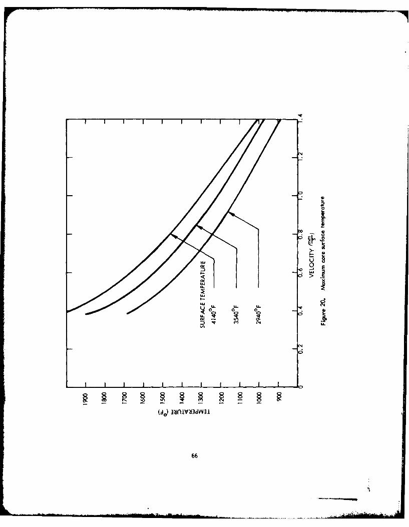
E 0
0 -
uu-
CLL
LU LL U- -
66
fPENETRATOR \
300 91D)IRECTION Of
TRAVEL
C%4200 ~
4*
il0o
-2
0 o.2 0.4 0.6 0.9
*seer Tab e. p netr tr cylindrical Surface heat flux dis ri bu~tio nls
67
Table 4
Penetrator Heat Transfer Characteristics
1 2 3 4Earth Material MASIG -UlCOW MASG- MASI
Penetrator Transit Time (sec)** 650 650 650 325
Penetrator Surface Temperature (F) 3540 3540 2940 3540
Penetratar Side Surface HeatTransfer Rate (MW)+ 0.12 0.05 0.09 0.16
Approximate Penetration Rate(mnV/sec) 0.5 0.5 0.5 1.0
Front Surface Heat TransferRate (MW) 0.15 0.10 0.15 0.30
Total Penetrator Power Level(MW) 0.27 0.15 0.24 0.46
Refers to the curve in Figure 21 with the same identifying number
Time required to move a distance equal to the heated length of the penetrator
+ For this calculation, the penetrator heated length was assumed toe 12.0 in.Further, the penetratar side surface area was enlarged to 100.0 in. per in. to accountfor extended surfaces
68
........
whereH - earth heat content required for melting - Joules/gm
U p penetration rate - mnVsecp 2A melt cross-sectional area - mm
m earth density - gnVmm 3
eOF = front surface power requirement - MW
As on example, consider the conditions for Curve 4 In Figure 21. In that
case,
H 1856 Joules/gm
V 1. 0 mnmsec
A - (11.02 3.02) 88.0 in2 56,770mm2
P 2.8 x I0-3 gn/mm 3
Therefore,
0 F (1.0 x 10 -6) (1856) (1.0) (56,770) (2.8 x 10⁻³
QF =0.30 MW
and the total penetrator power requirement (excluding heat losses to the stem region) would
be 0.51 MW.
119. In summary, the primary purpose of this section involves prediction of the
transient temperature distribution in the earth surrounding the path of the EMP. The UNCON
and MASIG geological models were considered and the analysis shows that temperature
variations will occur at larger radial distances from the penetrator for MASIG material because
of its relatively large thermal conductivity. The analysis also shows that liner cooling air
can withdraw much of the energy added to the earth by the EMP within 1 hour after passage
of the penetrator. During that time, the MASIG temperature changes were restricted to a20-in. radius of the EMP centerline. For longer cooldown periods, the temperature of the
liner cooling air will control the earth temperatures in the vicinity of the EMP. If high
cooling air temperatures cannot be avoided and if the eurth temperature perturbations
are to be restricted in a certain EMP application, it may be necessary to operate the
penetrator with a periodic melting/cooling cycle.
69

I Hole Logglnrl
120. Two principal changes occur in the passage of the penetrator. First, the
groundmoss temperature is temporarily elevated and, second, a glass liner is Formed. Each
of these can effect logging results as described in the ollowing discussions.
Remanent magnetism
121. Most rocks owe their magnetism to their content of various Iron oxides and
to their solid solution with titanium oxides. Igneous rocks acquire most of their magnetism
as they cool through the Curie temperature. The Intensity of this thermo-magnetic
remanence is dependent on the age of the rock (Reference 6). The Curie temperature is a
function of composition, but for many rocks is approximately 850 K (Reference 7). Previous
temperature distribution curves indicate that the 850 K isotherm does not extend more than
5 inches from the penetrator. However, Reference 6 Indicates that the natural remanent
magnetization can be Increased by up to a factor of 5 in the volume of rock that exceeds
the Curie temperature, the older the rock, the bigger the factor.
Neutron logs
122. Neutron sources that are used in well logging emit high energy neutrons.
Neutron detectors that are used in well logging are most sensitive to low energy neutrons
in the thermal (0. 025 eV) and low eV range.
123. Consequently, neutron logging instruments are always sensitive to the neutron
scattering properties of the materials near the neutron source. The scattering properties that
are important are the neutron scattering cross section of the nuclei and the mass of the
scattering nuclei. The larger the scattering cross section for fast neutrons, the more
frequent the collisions. Hydrogen has the highest scattering cross section of all nuclei.
124. The mass of the nucleus is important in determining the amount of energy aneutron loses in a collision with a nucleus. The lower the mass, the higher the energy loss.
Consequently, hydrogen is the most effective atom involved in slowing down neutrons from
the originating energy in the MeV range to the detection range of a few eV or less. For
this reason, neutron logging is most often used For determination of the hydrogen present
In rocks. Since hydrogen is found in the pore spaces, in the form of water or hydro-
carbons, the response of the logging system is primarily a function of porosity If the geologicmaterial is fully saturated.
70
* . &.
125. Recent theoretical calculations of the slowing down length, I s, required toslow neutrons down from the fast neutron emission energy to 0. 215 eV have been made. The
results are consistent with experimental measurements when graphite, water, and S 102 are
used as the slowing down media. Hence, these calculations should be realistic for sandstone,
limestone, and dolomite. They clearly demonstrate that the loss of water from the rocks
increases the slowing down distance by a factor of about 3 (. e., from about 7.2 cm to about
19.2 cm) for a Ra Be source.
126. Inasmuch as the passage of the EMP will completely dehydrate the rock that
is in the glass liner, and will partially dehydrate the surrounding rock, It is evident that the
effect of the EMP will be to increase the effective slowing down length for neutrons in the
material that surrounds the hole. This increase is caused by a reduction in the macroscopic
scattering cross section of the rock.
127. As noted in the preceding paragraphs, the dominant change in the operation
of a neutron log is likely to occur in the slowing down properties of the rock. This is
proportioned to the epithermal scattering cross section and is inversely proportional to
the nuclear mass. As water is driven out of the rocks, the epithermal macroscopic scatter-
ing cross section for the rock will decrease somewhat. The loss in the Z 1 I hydrogen
nuclei should be more important than the decrease in the scattering cross section.
128. Some neutron logs depend on the macroscopic capture cross sections of
hydrogen to detect the amount of hydrogen present. The passage of the EMP will cause
dehydration of the glass liner and partial dehydration of the surrounding rock. Hence,
the thermal macroscopic cross section of the rock will decrease.
129. Epithermal neutron inelastic scattering cross sections are used in instruments
that measure the carbon to oxygen ratio in rocks. Dehydration of the rock will not affect
these cross sections as such. However, the C is connected with a hydrocarbon and the
O with water. High rock temperatures will drive out water and hydrocarbons. Hence,
the C/O ratio will not be the same as it would have been prior to the passage of the EMP.
130. Epithermal neutron capture cross sections might be used with 14-MeV neutron
sources to identify minerals by activation techniques. Dehydration will not change the
cross sections. However, the loss of water and hydrocarbons from the rock will allow the
71
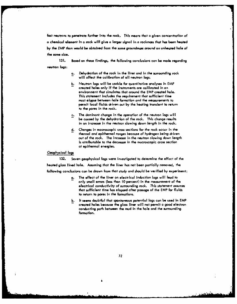
fast neutrons to penetrate farther into the rock. This means that a given concentration of
a chemical element in a rock will give a larger signal in a rockmass that has been heated
by the EMP than would be obtained from the some groundmass around an unheated hole of
the same size.
131. Based on these findings, the following conclusions can be made regarding
neutron logs:
a. Dehydration of the rock in the liner and in the surrounding rock- will affect the calibration of all neutron logs.
b. Neutron logs will be usable for quantitative analyses in EMPcreated holes only if the Instruments are calibrated in anenvironment that simulates that around the EMP created hale.This statement includes the requirement that sufficient timemust elapse between hale formation and the measurements topermit local fluids driven out by the heating transient to returnto the pores in the rock.
c. The dominant change in the operation of the neutron logs willbe caused by the dehydration of the rock. This change resultsin an increase in the neutron slowing down length in the rock.
d. Changes in macroscopic cross sections for the rock occur in the- thermal and epithermal ranges because of hydrogen being driven
out of the rock. The increase in the neutron slowing down lengthis attributable to the decrease in the macroscopic cross sectionat epithermal energies.
Geophysical (lgs
132. Seven geophysical logs were investigated to determine the effect of the
heated glass lined hole. Assuming that the liner has not been partially removed, the
following conclusions can be drown from that study and should be verified by experiment:
a. The effect of the liner on electrical Induction logs will lead toonly small errors (less than 10 percent) in the measurement of theelectrical conductivity of surrounding rock. This statement assumesthat sufficient time has elapsed after passage of the EMP for fluidsto return to pores in the formations.
b. It seems doubtful that spontaneous potential logs can be used in EMPcreated holes because the glass liner will not permit a good electronconducting path between the mud in the hole and the surroundingformation.
72
&i
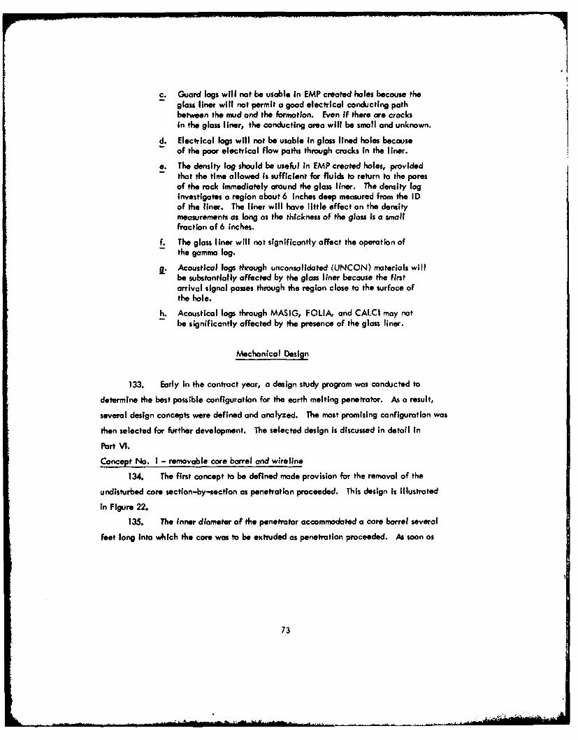
c. Guard logs will not be usable in EMP created holes because the- glass liner will not permit a good electrical conducting path
between the mud and the formation. Even if there are cracksin the glass liner, the conducting area will be small and unknown.
d. Electrical logs will not be usable in glass lined holes because- of the poor electrical flow paths through cracks in the liner.
e. The density log should be useful in EMP created holes, provided- that the time allowed Is sufficient for fluids to return to the pores
of the rock Immediately around the glass liner. The density loginvestigates a region about 6 inches deep measured from the IDof the liner. The liner will have little effect on the densitymeasurements as long as the thickness of the glass is a smallfraction of 6 inches.
f. The glass liner will not significantly affect the operation ofthe gamma log.
j. Acoustical logs through unconsolidated (UNCON) materials willbe substantially affected by the glass liner because the firstarrival signal passes through the region close to the surface ofthe hole.
h. Acoustical logs through MASIG, FOLIA, and CALCI may notbe significantly affected by the presence of the glass liner.
Mechanical Design
133. Early in the contract year, a design study program was conducted to
determine the best possible configuration for the earth melting penetrator. As a result,
several design concepts were defined and analyzed. The mast promising configuration was
then selected for further development. The selected design is discussed in detail In
Part VI.
Concept No. I - removable core barrel and wireline
134. The first concept to be defined made provision for the removal of the
undisturbed core section-by-section as penetration proceeded. This design is Illustrated
in Figure 22.
135. The inner diameter of the penetrator accommodated a core barrel several
feet long into which the core was to be extruded as penetration proceeded. As soon as
73

the core completely filled the core barrel, a release mechanism would be activated and
the core barrel and core would be withdrawn to the portal by means of a wireline. Activa-
tion of the release mechanism would be via the wireline tension or could be effected
directly through contact with the end of the core. The latter alternative, used with a
wireline maintained constantly under tension, would eliminate the need for instrumentation
to signal contact of the core end with the bottom of the core barrel. After removal of the
core from the barrel at the portal, the core barrel would be reinserted Into the penetrator
stem and propelled by compressed air to the penetrator head location to await its next
refilling.
136. The penetrator head, machined from tungsten, accommodated 12 cylindrical
heaters in equally spaced axial holes around the penetrator axis. The heaters were made up
of stocked washers of pyrolytic graphite and were located in their holes by means of spring
loaded tungsten electrodes, along which direct current was supplied from transformers in the
stem. The molten rock was fed through a series of holes and grooves, machined in the
penetrator head, to twelve carry-off tubes equally spaced around the penetrator axis. The
12 carry-off tubes connected with an annular carry-off passage in the stem. The annular
passage had to be interrupted at the stem section joint to provide structural support for
the inner diameter of the stem. The narrow annular carry-off passage made available an
uninterrupted annular space around it in the stem which was capable of accommodating a
guidance sensor up to 2 inches in diameter or transformer modules of similar size.
137. High pressure air was supplied to the outer passage at the portal and flowed
to the penetrotor where it entered the injection nozzles at the penetrator end of the carry-off
tubes. Molten rock, extruding into the carry-off tubes, was then broken up into fine
particles by the high velocity air emerging from the nozzles and transported pneumatically
to the portal.
138. A portion of the high pressure air supplied to the outer annular passage was
allowed to exhaust through a number of holes in the hole former area to cool the transition
from the penetrator to the stem. Insulation, in the form of pyrolytic graphite rings, was
employed to limit the heat conducted into the stem. A gradation of material temperature
capability was employed between the tungsten penetrator head and the aluminum stem.
74
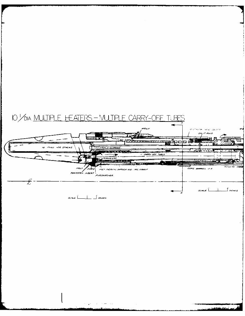
10' DIA. MULTIPLE HEATERS - MULTIPLE CARRY-OFF TUBES
A 04 0
M~~ ~ ~ CAW 0A- a6
A'2 y Y* AM&Y r$ A vfqIZ AA/O 14V '4~ l 3h+OA
relw$7asrz ,A'sc.c
LLJ k,
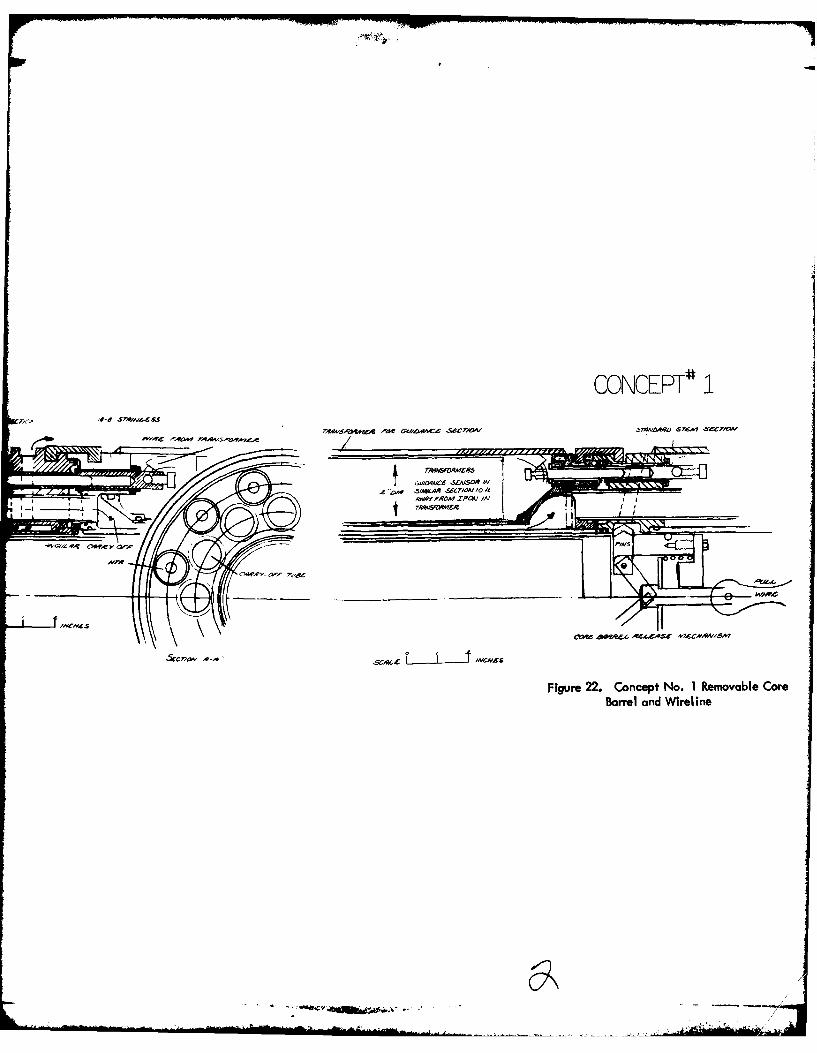
CONCEPT # 1
'S-IC- AVwS&
10 AI
Figure 22. Concept No. 1 Removable CoreBarrel and Wireline
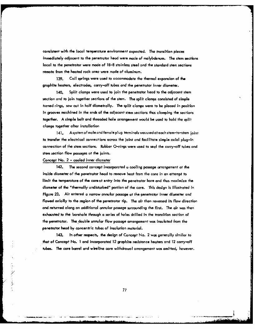
consistent with the local temperature environment expected. The transition pieces
immediately adjacent to the penetrator head were made of molybdenum. The stem sections
local to the penetrator were made of 18-8 stainless steel and the standard stem sections
remote from the heated rock area were made of aluminum.
139. Coil springs were used to accommodate the thermal expansion of the
graphite heaters, electrodes, carry-off tubes and the penetrator inner diameter.
140. Split clamps were used to join the penetrator head to the adjacent stem
section and to join together sections of the stem. The split clamps consisted of simple
turned rings, saw cut in half diametrally. The split clamps were to be placed in position
in grooves machined in the ends of the adjacent stem sections thus clamping the sections
together. A simple bolt and threaded hole arrangement would be used to hold the split
clamps together after installation
141. Asystemof male and female plug terminals was used at each stem-to-stem joint
to transfer the electrical connections across the joint and facilitate simple axial plug-in
connection of the stem sections. Rubber O-rings were used to seal the carry-off tubes and
stem section flow passages at the joints.
Concept No. 2 - cooled inner diameter
142. The second concept incorporated a cooling passage arrangement at the
inside diameter of the penetrator head to remove heat from the core in an attempt to
limit the temperature of the coreat entry into the penetrator bore and thus maximize the
diameter of the "thermally undisturbed" portion of the core. This design is illustrated in
Figure 23. Air entered a narrow annular passage at the penetrator inner diameter and
flowed axially to the region of the penetrator tip. The air then reversed its flow direction
and returned along an additional annular passage surrounding the first. The air was then
exhausted to the borehole through a series of holes drilled in the transition section of
the penetrator. The double annular flow passage arrangement was insulated from the
penetrator head by concentric tubes of insulation material.
143. In other respects, the design of Concept No. 2 was generally similar to
that of Concept No. I and incorporated 12 graphite resistance heaters and 12 carry-off
tubes. The core barrel and wireline core withdrawal arrangement was omitted, however.
7
~77

The penetrator head incorporated a finned exterior surface to promote the transfer of heat
from the penetrator head to the rock.
Concept No. 3 - annular heater and carry-off tubes
144. In this arrangement, the 12 separate cylindrical heater geometry was
replaced by an annular configuration divided into three 120-degree sectors. The concept
is illustrated in Figure 24. The thre&-sector arrangement was intended to provide the
necessary steering capability by appropriate modulation of the power to the three sectors.
The location of the heaters in the heater annulus was effected by a system of spring loaded
tungsten electrodes similar to that employed in Concepts No. I and No. 2.
145. An annular carry-off tube geometry employed in this design also provided
some cooling of the core as it entered the penetrator inner diameter. Air flowing along
the outer annulus of the stem was fed into the outer of two narrow annular passages around
the inner diameter of the penetrator. In the region of the leading edge of the penetrator,
the air was injected into the inner annular passage in the reverse direction through a narrow
annular nozzle and.at this point, contacted the molten rock being extruded from the
extended surface channels of the penetrator head into the carry-off passage.
146. The high velocity annular air jet then sheared the molten rock stream,
breaking it up into small particles, and transported the rock to the portal along the inner
annulur flow passage.
Concept No. 4 - annular heater with four carry-off tubes
147. In Concept No. 4, the annular heater arrangement was used together with
four separate carry-off tubes. The annular heater was divided into four 90-degree sectors,
each sector being located in the heater annulus by two spring loaded tungsten electrodes,
one on each side of each carry-off tube. The design is illustrated in Figure 25.
148. For this arrangement, the inner diameter of the penetrator was insulated
from the entering core by pyrographite insulation tubes and no provision was made for
cooling the core. The molten rock was fed to the carry-off tubes through drilled passages
from a circumferential groove in the penetrator periphery which, in turn, received molten
rock from the extended surface fins machined axially along the outer diameter of the
penetrator.
78
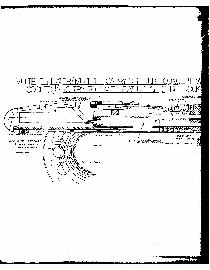
MULTIPLE HEATER/ MULTIPLE CARRY- OFF TUBE CONCEPTCQQLEDTO TY TLIMIT HA-UP OFCR O
%xw/ r 9/
0 00 0 00 0
5'-e lo/ V -,q~
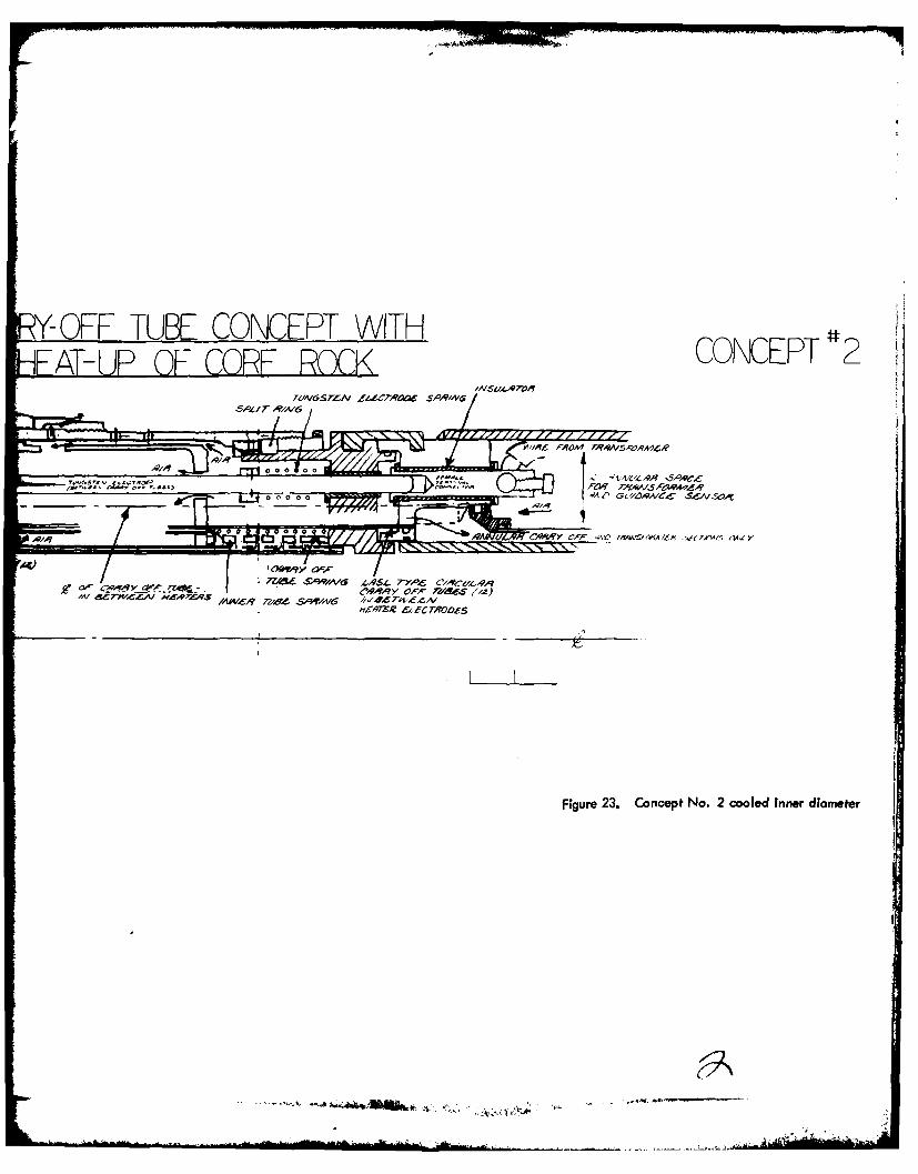
YOFF TUBE CONCEPT WITHCOEP2
AIRuLrO
WI06 PROMt-V5,vA4AR
00 0 0 0
0l~ 0 0 ,Q d CAWRY 0FPi4V - A 7AA-W / f ' axy
1AICR -11Z S0TI16 1.19-1;ZR ICTO
Figure 23. Concept~ No. 2 cooled inner diameter
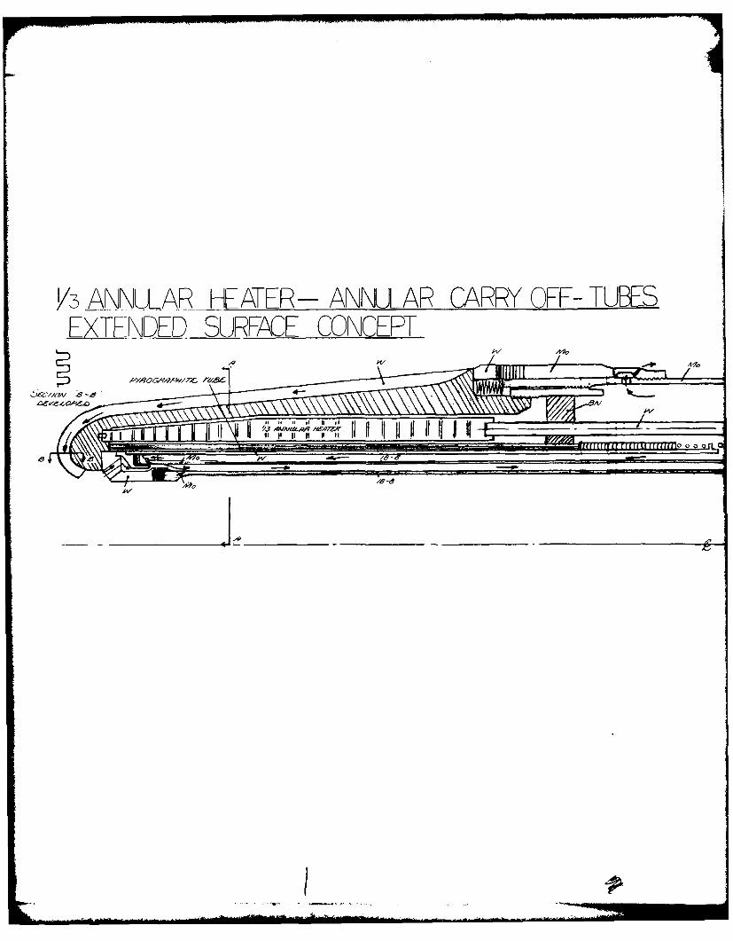
V3 ANNWtAR HEATER- ANNULAR CARRY OFF- TUBEEXTENDED SURFACE CONCEPT
w Iw
AxfqrIOAI,~ 6 -Aff
)LZ'/21)A/ 8-8/P70
PRY OFF- TUBES CONCERT 3
A4 ( ooo
0 abO IL
Figure 24. Concept No. 3 annular heaterand carry-off
/AWAULAR- HEATER 4 ENLARGED CARRY OFF TUBESAYAO "A~L.O AZS1.S7~C-- q ZOA" 4ff"
TuN~rrA F~vmr//qpyA~AA~Ar.~AeS57.4C~e Te4657A/ Mai ~
u~iitiIIJI~t~iII - -- ~II~lIII~I~III~jRnee"
CONCEPT 1i4
.1~~~A .. *AacO A1901 ~ /0MtY
-%%,v G ___________________________
Figur 257ocp-o anlrhae n
~ff~four carry-of tubesI~
Concept No. 5 - nine heaters with three carry-off tubes
149. This arrangement provided three Independently controllable heating sectors,
each of which contained three resistance heater elements constituting the load of a
three-phase circuit. Thus, each heater was connected via Its spring loaded tungsten
electrode, male and female interstem connectors and wiring to the secondary winding of
one of the three transformer modules of a three-phase circuit. The nine transformer
modules were accommodated in the stem in three groups of three in the spaces between the
three carry-off tubes. The molten rock was fed to the carry-off tubes via drilled passages
from a circumferential groove machined into the finned periphery of the penetrator in a
similar manner to that of Concept No. 4. Concept No. 5 is illustrated in Figure 26.
Concept No. 6 - similar to Concept No. 5 butwith rock flow into penetrator leading edge
150. Although generally similar to Concept No. 5, this design incorporated
three large diameter axial holes, drilled from the leading edge of the penetrator in line
with the carry-off tubes. Concept No. 6 is illustrated in Figure 27. Provision was thus
made to accommodate the flow of a large portion of the molten rock directly from the leading
edge of the penetrator to the carry-off tubes. Smaller holes were drilled radially into the
axial holes from a circumferential groove machined into the penetrator head at the end
remote from the leading edge. These holes were intended to channel rock flowing into the
annular groove from the extended surface fins into the carry-off tube flow path. Thus, the
design provided for the flow of molten rock from both ends of the penetrator head.
However, consideration of the required rates of rock removal at various locations on the
penetrator suggested that the radial holes might not be desirable.
151. The required rate of rock removal directly ahead of the penetrator leading
edge must equal the advance rate into the rock. The corresponding rate of rock removal
on the outer periphery is greatly reduced by the oblique angle presented by the surface to
the direction of motion. Thus, the advance rate is limited by the rate of heat transfer at
the leading edge. Some improvement can be made by concentrating the heating at the
leading edge by appropriately increasing the heater resistance in this region. However,
the temperature limitations of the penetrator material must be observed and heat transfer
85
rates are limited by the low coefficient of heat transfer to the rock prevailing in the melting
region. If the heat transfer coefficient In the leading edge region could be increased by
forcing a high velocity flow of rock across the melting region, some Improvement in heat
transfer should be obtainable. To this end, rock might be melted on the peripheral surface
at a low rate of removal and forced to flow to the leading edge where it would provide a
high velocity flow stream across the melting face and also transport heat from the peripheral
surface to the leading edge by mass transfer. The development of such a heat transfer
mechanism would be a worthwhile goal of an experimental program.
Electrical Design
Heaters
152. As shown in Figure 27, nine heaters will be mounted within the penetrator.
Various heater types were considered. These included tungsten filament and graphite type
heaters. Since heater flux densities are high to produce the required temperatures and
considerations given to slight vibration within close tolerances, wire filament and filament
mesh heaters were eliminated because of heater "sag."
153. A number of suppliers were contacted to determine the characteristics of
graphite materials available for heater construction. Two of the suppliers produce a fine
grain-high purity graphite material that could be used. One of these two suppliers has
capability for a pyrolytic graphite coating on fine grain graphite. The third supplier
produces pyrolytic graphite up to 0. 5-inch thick for normal production. Special runs have
been made up to a 3-inch depth; however, this is not a typical run and the material is
quite expensive. Table 5 shows the physical property information received from the various
suppliers of graphite. There is a difference between extrapolated data from LASL and the
vendor "C" data (Columns B and C of Table 6).
154. Since graphite heaters require high currents and relatively low voltages,
only pyrolytic graphite heaters are being considered because of its resistivity characteristics.
86
9- -EATEPS - 3 PER CIRCUIT (I2O0SEGTOR) -9 TRANSFORMER MODILES - 3 CARRY OFF-TUBESPER PHASE (30) 1 PER PHASE (30)
~~tA A,.&q 5 "A/ d-Ecc 7raoz
ZX7,F'O440~Ye
A' Y -4 -)*qo -Yq 6W IA_ 4440YA4C 710%.0 ,A~ 1.' *W
- ______ -___ ___ ___ ___ ___ - _________ &O X'44- . *se,
~ ~' , 17
F-TUBES CONCEPT 5
cwqv oa- C 4CCflr,, 44
,nooc Ot,46
I? % 6 '0 S~fA~L5~5 3Ze21 A'.
-fr 7%A~,7*,- 4 JM00Z, 1
S7/
three caryof tubes'~
92 DAMETEP PENETRATOR -8" PIP STEM
e~r7F7O Sovcl i~ ~ ~,~AC6~'EA~. 9
£vAn .' 4 6A iv
13 -AW / 0,,, A 4~low (jt)
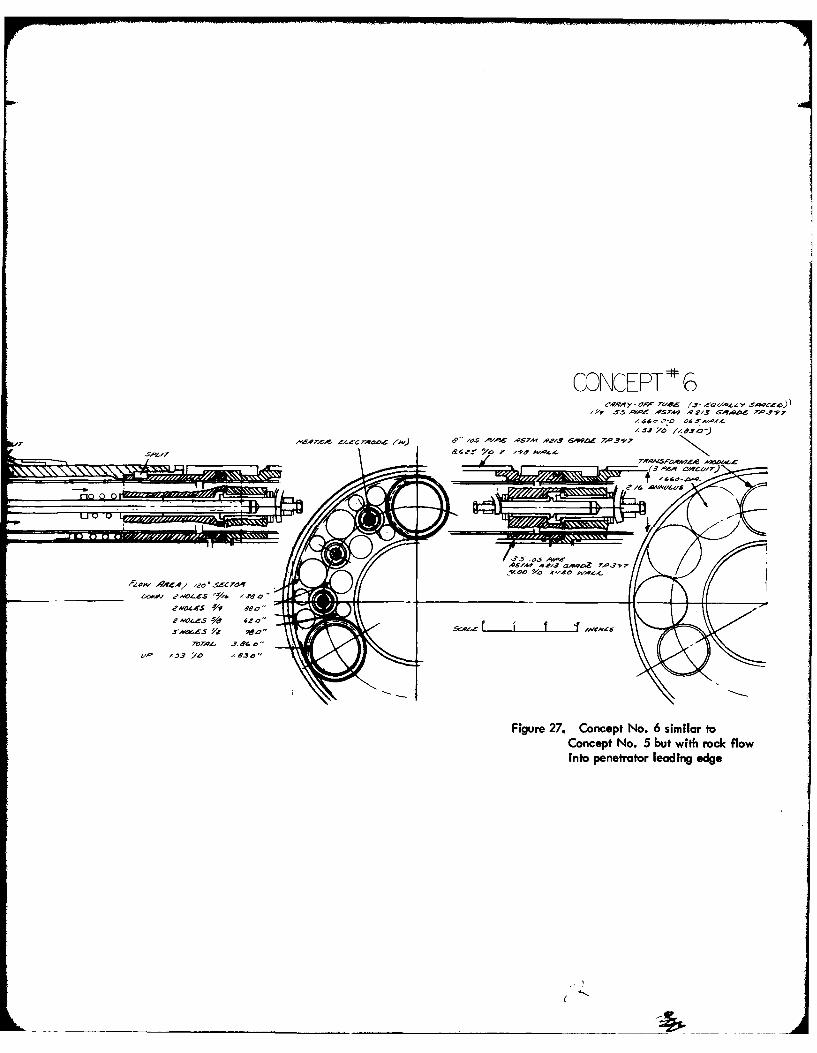
CONCEIPT 6SY .5 'Or, A.9 A213 Gq.qAd Z .9
ddI - -SAMD-I
o~~~0 riM2 e'l& AWZ~
ff43 'd 83oI
Figure 27. Concept No. 6 similar toConcept No. 5 but with rock flowinto penetrator leading edge
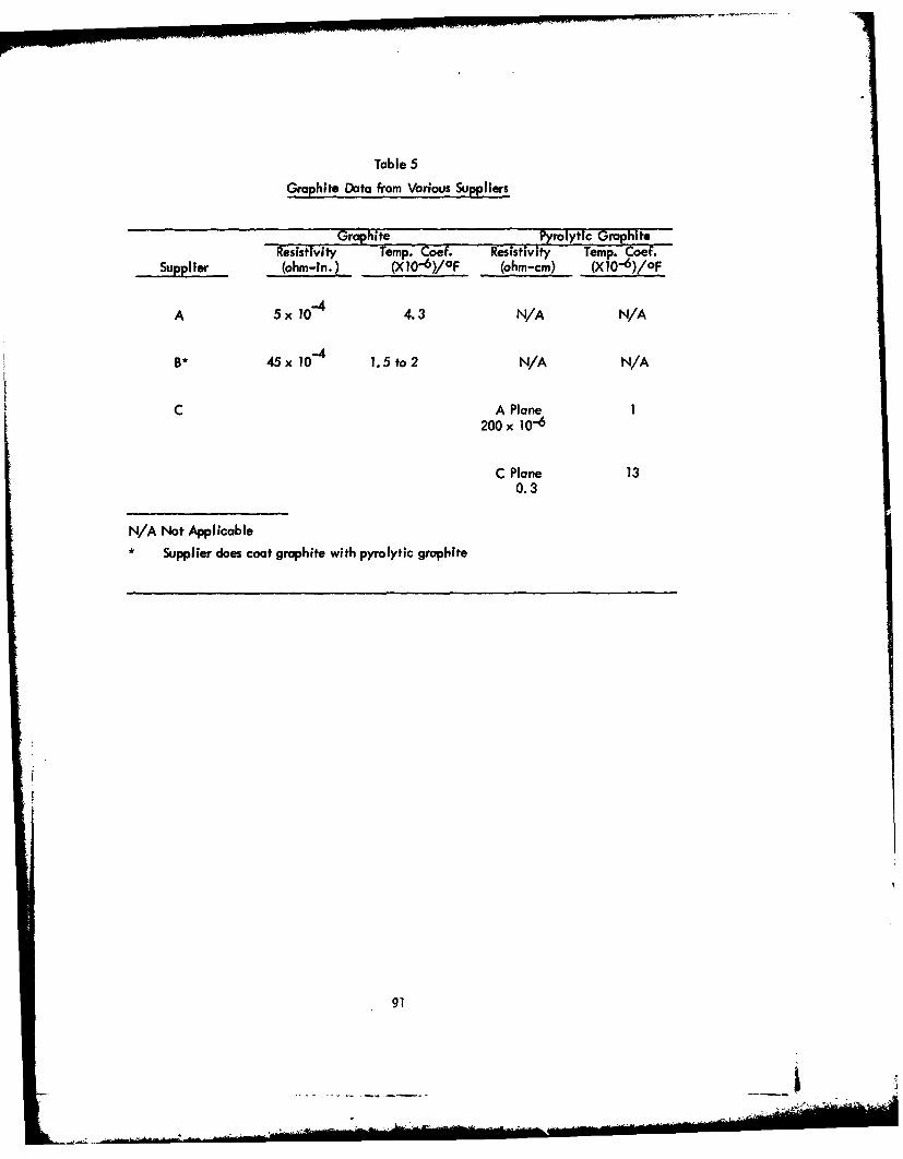
Table 5
Graphite Data from Various Suppliers
Graphite Pyrolytic GioaphiteResistivity Temp. Coef. Resistivity Temp. Coef.
Supplier (ohm-in.) (X 10 6 )/oF (ohm-cm) (X10-6)/OF
A 5x 10 -44.3 N/A N/A
-4B*45xl10 1.5 to 2 N/A N/A
C A Plane 1200 x 10-6
C Plane 130.3
N/A Not Applicable* Supplier does coat graphite with pyrolytic graphite
91
In addition, pyrolytic graphite exhibits good conductivity in the "A" and "B" planes which
will allow for radial heat transfer in the penetrator body.
155. The present heater physical size under consideration is I inch in diameter
and 10 inches long. Initial calculations and heater configurations are based on the LASL
84-mm penetrator design. Table 6 shows the comparison of heater designs based on the
LASL penetrator and vendor supplied data. Column A represents data determined from the
LASL 84-mm penetrator. Column B shows the calculated heater data for the same configura-
tion for a 10-inch-long, 1-inch-diameter heater. Column C shows heater values using
supplier "C" data. Column D shows heater data assuming that the entire heater is made of
pyrolytic graphite from supplier "C."
156. To protect the tungsten within each heater compartment, a pyrolytic
graphite sleeve will be used. In addition, a flow of helium gas will exist within the annulus
between the heater and the sleeve to operate the heater in an inert environment. For any
given distance between electrodes in a gas, there is some critical pressure at which discharge
occurs at the minimum sparking potential of the gas. Thus, with a gap of 3 millimeters in
air, spark-over occurs at a pressure of 1.5 millimeters at about 340 volts. For a gap of
I millimeter, the discharge occurs at a pressure of 5 millimeters at the same voltage. At
pressures above and below these minima, or critical pressures, the voltage necessary to
produce breakdown of the gas increases with both increasing gap size and decreasing pressures.
Therefore, the sparking potential of a gas is a function only of the product of the sparking
distance and the pressure of the gas between the electrodes. If P, the pressure, and D,
the gap length, are varied in such a way that the product PD remains constant, the
sparking potential will remain unaltered, and the product PD is a constant for any gas.
For helium, the minimum spark potential is 261 volts with PD at 27 mm Hg . mm.
157. Tungsten electrodes will be utilized between the heater and input power
connector. Tungsten comes in various forms which include "black, " "clean, " and"ground. " For the heater electrodesthe "clean" form will be utilized with the terminating
ends "ground" to mate the interfacing components. Lengths of up to 48 inches that are
available will satisfy the penetrator requirements.
92
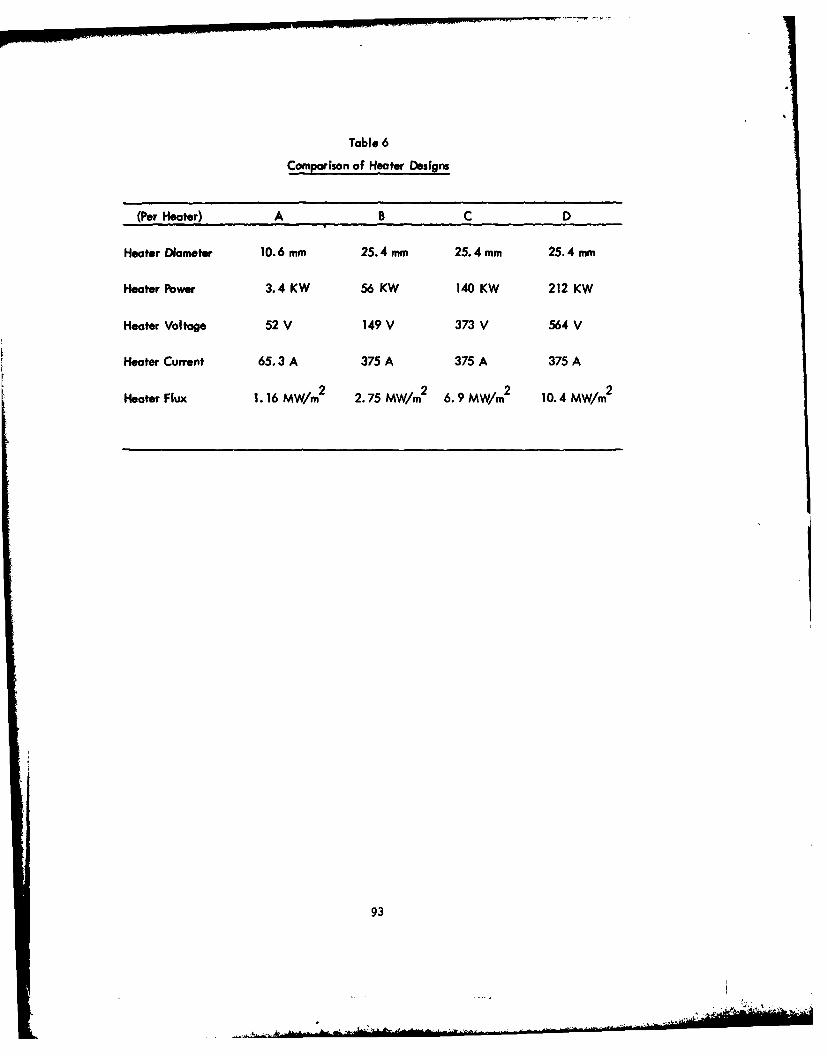
Table 6
Comparison of Heater Designs
(Per Heater) A B C D
Heater Diameter 10. 6 mm 25.4 mm 25.4 mm 25.4 mm
Heater Pbwer 3.4 KW 56 KW 140 KW 212 KW
Heater Voltage 52 V 149 V 373 V 564 V
Heoter Current 65.3 A 375 A 375 A 375 A
Heater Flux 1. 16 MW/in2 2.75 MW/m 2 6.9 MW! 2 104 MW/m2
93
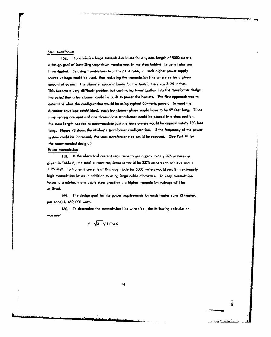
Stem transformer
158. To minimize large transmission losses for a system iorngth of 5000 meteis,
a design goal of installiNg step-down transformer% In the stem behind the penetrator was
Investigated. By using transformers near the penotrator, a much higher power supply
source voltage could be used, thus reducing the transmission line wires size for a given
amount of power. The diameter space allowed for the transformers was 3. 25 Inches.
This become a very difficult problem but continuing Investigation Into the transformer design
Indicated that a transformer could be built to power the heaters. The first approach was to
determine what the configuration would be using typical 60-hertz power. To meet the
diameter envelope established, each traisformer phase would have to be 59 feet long. Since
nine heaters are used and one three-phase transformer could be placed In a stem section,
the stem length needed to accommodate just the transformers would be approximately 180 feet
long. Figure 28 shows the 60-hertz transformer configuration. If the frequency of the power
system could be Increased, the stem transformer size could be reduced. (See Part VI for
the recommended design.)Power transmission
Is8. If the electrical current requiremetits ore approximately 375 amperes ais
given In Table 6, the total current requiremenit would be 3375 amperes to achieve about
1.25 MW. To transmit currents of this magnlitude for 5000 meters would result In extremely
high transmission losses In addition to using large cable diameters. To keep transmission
losses to a minimum and cable sizes practical, a higher transmission voltage will be
utilized.
159. The design goal for the power requirements for each heater zone (3 heaters
per zone) Is 450, 000 watts.
160. To determine the transmission line wires sire, the following calculation
was used:
N5 4 V I Cos 4
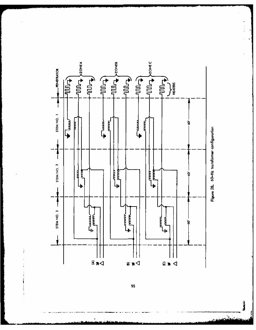
0 U
z z z
0 0 0A4
z
U,,
10
C~04
il
C.
TF-
-I 295
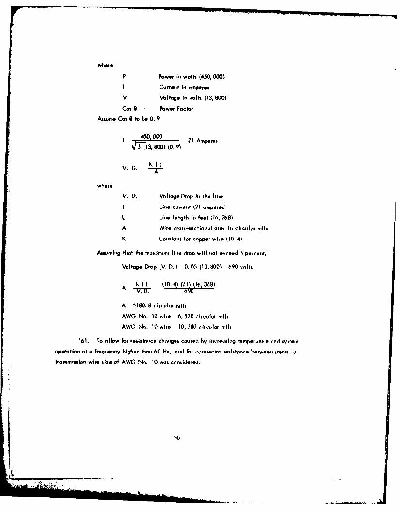
where
P Power inI watts (450, 000)
I Current III amperes
V %ltge InI volts (13. 800)
Cos 9 Power Factor
Assumeo Cos, 0 to be 0.9V
1 45000021A m
V.D. KI L
where
V. 0. Voltage Dronp in the line
I Line current 2 1 amperes)
L Line fength InI foot 0I6,,W6)
A Wire cross-sectional area inI circular mils
K Conistant for copper wiie 4(10. 4)
Assuming that the moxiim~ lie drop will not excoed 5 percent,
\oltoge Dtop (V. D. ) 0. 05 (13, 800) 690 volts
A K I L (10.4 Cf211 (16.,368)
A 5 180. 8 circular nills
AWG No. 12 wire 6, 530 circuts miis
AWO No. 10 wifre 10, 380 circular mnils
161. To allow for resistance changes caused by ioicronsing tempewatuto amid system
operation at a frequency higher Oham 60 Hs, ond for connector resistance betweeni stems, a
j frarmission wire site of AWO No. 10 was considered.
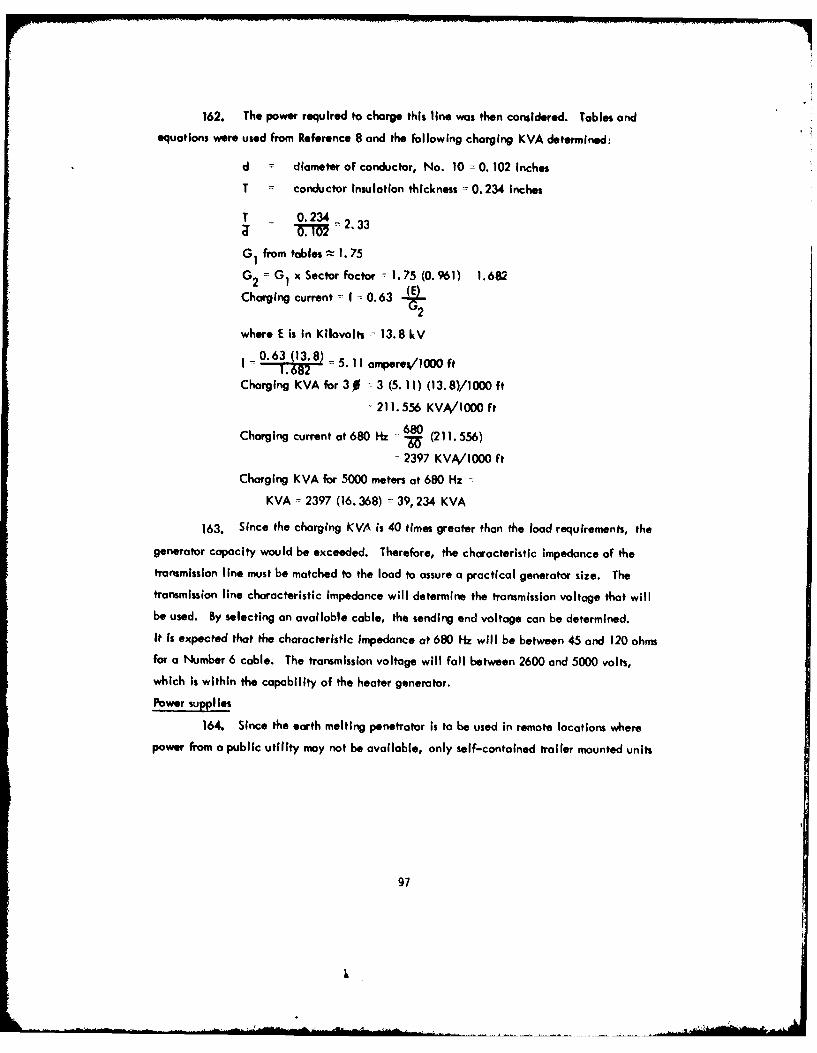
162. The power required to charge this line was then considered. Tables andequations were used from Reference 8 and the following charging KVA determined:
d = diameter of conductor, No. 10 = 0. 102 Inches
T = conductor insulation thickness = 0.234 Inches
T 0.234a w = 2. 33
GI from tables z 1. 75
G2 = G Ix Sector factor - 1.75 (0.961) 1.682
Charging current = I = 0.63 (E)
where E is in Kilovolts - 13.8 kV
I = 0.63 (13.8) = 5. If ampere%/1000 ft1.6982"
Charging KVA for 30 3 (5. 11) (13.8)/1000 ft-211.556 KVA/1000 ft
Charging current at 680 Hz 6 80 (211. 556)
- 2397 KVM/1000 ft
Charging KVA for 5000 meters at 680 Hz
KVA - 2397 (16.368) = 39,234 KVA
163. Since the charging KVA is 40 times greater than the load requirements, the
generator capacity would be exceeded. Therefore, the characteristic impedance of the
transmission line must be matched to the load to assure a practical generator size. The
transmission line characteristic impedance will determine the transmission voltage that willbe used. By selecting an available cable, the sending end voltage can be determined.
It Is expected that the characteristic Impedance at 680 Hz will be between 45 and 120 ohms
for a Number 6 cable. The transmission voltage will fall between 2600 and 5000 volts,which is within the capability of the heater generator.
Power supplies
164. Since the earth melting penetrotor is to be used in remote locations wherepower from a public utility may not be available, only self-contained trailer mounted units
97
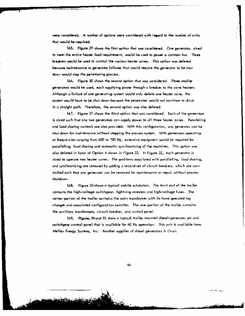
were considered. A number of options were considered with regard to the number of units
that would be required.
165. Figure 29 shows the first option that was considered. One generator, sized
to meet the entire heater load requirement, would be used to power a common bus. Three
breakers would be used to control the various heater zones. This option was deleted
because maintenance or generator failures that would require the generator to be shut
dowi would stop the penetrating process.
166. Figure 30 shows the second option that was considered. Three smaller
generators would be used, each supplying power through a breaker to the zone heaters.
Although a failure of one generoting system would only delete one heater zone, the
system would have to be shut down because the penetrator would not continue to drive
in a straight path. Therefore, the second option was also deleted.
167. Figure 31 shows the third option that was considered. Each of the generc.tors
is sized such that any two generators can supply power to all three heater zones. Pairaleling
and load sharing controls are also provided. With this configuration, oy generat'Os can be
shut down for maintenance without stopping the process system. With generators operating
at frequencies ranging from 600 to 700 Hz, extensive equipment would be required for
paralleling, load sharing and automatic synchronizing of the machines. This option was
also deleted in favor of Option 4 shown in Figure 32. In Figure 32, each generator is
sized to operate two heater zones. The problems associated with paralleling, load sharilg,
and synchronizing are removed by adding a second set of circuit breakers, which are con-
trolled such that any generator can be removed for maintenance or repair without process
shutdown.
168. Figure 33 shows a typical mobile substation. The front end of the trailer
contains the high-voltage switchgear, lightning arresters and high-voltage fuses. The
center portion of the trailer contains the main transformer with its hand operated tap
changer and associated configuration switches. The rear portion of the trailer contains
the auxiliary transformers, circuit breaker, and control ponel.
169. Figures 34and 35 show a typical trailer mokunted diesel-,enerator set and
switchgeor control panel that Is available for 60 Hz operation. This unit is available from
Melley Energy Systems, Inc. Another supplier of diesel generators is Onano.
98
. Aill
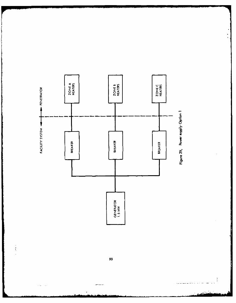
LW uw 205U
I-I
z
LU
C4
4----- - -0
U.99
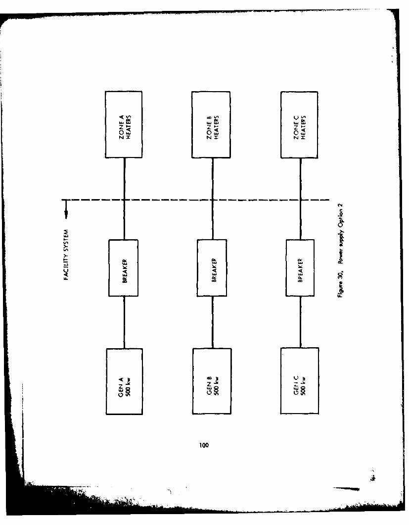
F,- WWI
N X
LILl
IL.
z
-i 1U1LOU
"Iww uj
-Az
T- -X
.0.
101
-, -~------.
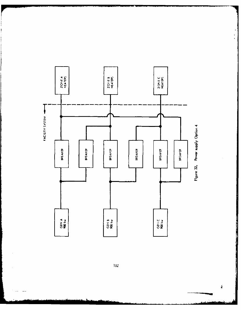
CD
LI
102
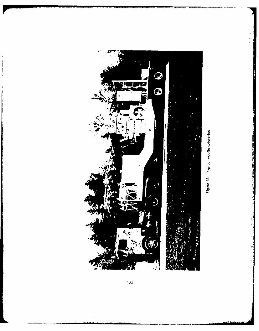
~ - I * ~ ~.,I.. -U' ~ -- -. - -
6
4:.
a1)
C.-,
los
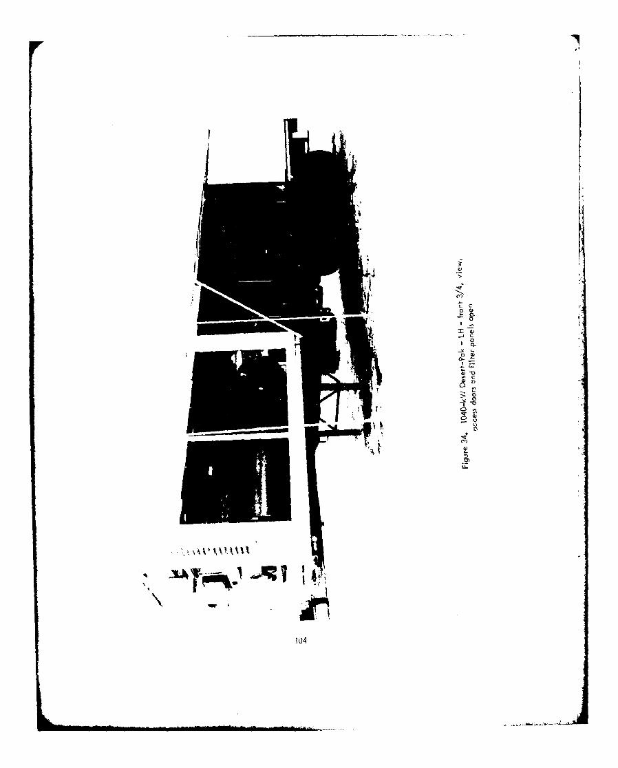
iiC
0 a
c C
104
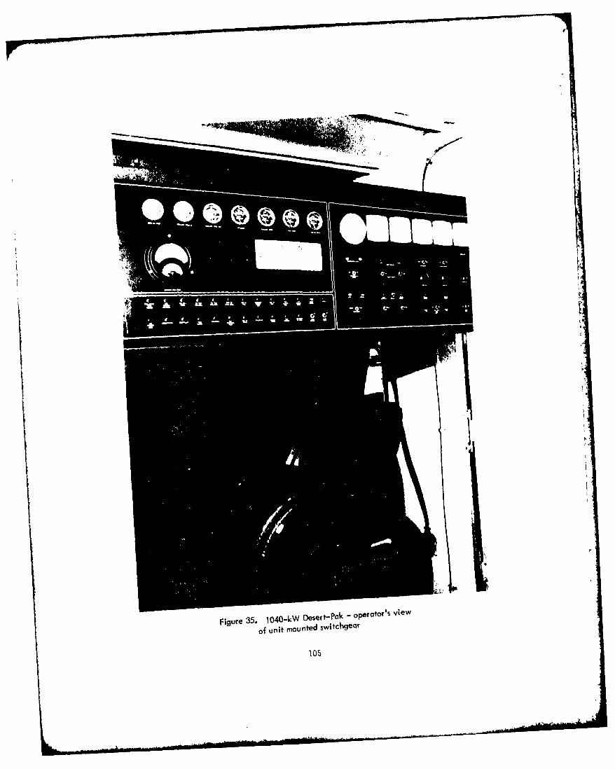
r
Figure 35. 1O40OkW Desert-Pak -oPeratorls view
of unit mounted switchgeo!
105

Guidance
170. The problem of accurate guidance through the earth is complicated by the
inhomogeneous, hostile, and unpredictable medium. Guidance of the earth melting probe
must be approximately 5 feet in 5000 feet or +0. 1 percent; data gathering must be nearly
continuous. If the guidance system is In the probe, then the guidance package must be
insulated from temperatures from 2000 to 2500 K. Magnetic fields caused by the 1000-ampere
AC power for the melting element will be huge. Howe%-r, drift in the system must be
negligible since the probe will be in the hole for extended periods of time, and the entire
package can be no more than 3-1/2 Inches high. If the guidance system Is a locator device,
it must be relatively unaffected by mountainous terrain and unknown inhomogeneities in
the earth. The possibility of encountering such unknowns as conducting materials, faults,
and small diameter vugs must be accounted for by the system.
171. Guidance systems will be judged in light of these potential problem areas.
Final evaluation will be determined by system performance in a horizontal bore hole Into
a mountain.
172. Several guidance systems are to be considered. A thorough treatement of
most of them Is given In Reference 9.
173. This text will be a summary of the applicability of the various guidance
systems to the problem of the earth melting probe. Ciavatto treats seven systems; two
others will be added. In an ideal situation, an above-ground mapping scheme would chart
the path of the penetrator by use of radio or sonar waves and the position of the penetrator
would be determined exactly. However, the state-of-the art In this field has not achieved
the sophistication to allow such detailed mapping.
174. Two surface antenna schemes have been worked out, one by Bell Labs
in 1968, and the other by the British Leader line system. In both systems, wires are laid
out over the intended path and the tunneler is guided by sensing the magnetic fields of the
wire. Neither system was every fully developed for underground use and neither accounts
for rugged terrain. Also, inhomogenities such as metal ores or faults would cause
unacceptable errors.
175. The underground radio homing device was not developed to the hardware
stage, but rather used a radio or sonic transmitter in the probe to signal a receiver at the
106

destination point. The antenna located the probe by one of two methods: relative field
strength, or travel time for pulse. While no data relative to the expected accuracy of
this system are available, It was not considered a primary method and was afforded a
low priorily.
176. Seismic position detectors have several advantages over other systems in
that the technology for detecting seismic sources through the earth is sufficiently advanced.
Earthquake and rock burst monitoring systems are capable of a high degree of accuracy,
given the dimensions of the problem. However, while Dudenhaven quoted an accuracy of
20 feet in less than 2 miles has been quoted, these locations involve sources capable of
much greater magnitude than can be expected from the earth probe. Large magnitude
sources greatly increase the signal to noise ratio. The level of accuracy offered by
present systems does not satisfy the original requirements. of the guidance system. Further-
more, the more complex the geology and seismic activity an area exhibits, the greater the
reduction in seismic locator system accuracy.
177. Although the light beam guidance system appears applicable to straight
line hole applications, it must be rejected because the proposed earth probe does not
provide an unobstructed path for the laser beam to follow. Drill casings, wire, melted
rock, and core effectively block the hole.
178. The inertial guidance system offers one possible solution to the accuracy
problem. One example of such a navigation system, the Singer-Kerfott F-16 system
(SKN-2416), has an accuracy of about 0. 1 percent. In addition, the inertial system could
give continuous pitch, yaw and roll data. The system is environmentally sensitive but
could be cooled to the necessary 200°F and pressure protected by the introduction of
cooling units and shielding. The effect of the magnetic fields is presently unknown, and
while the unit may be unaffected, it possibly could only be used during the shutdown time
as drill pipe is added. Unfortunately, the Singer-Kerfott system has a minimum height of
8 inches because of the gimbaling of the gyros. However, the N-73 or micron system,
designed and built by Rockwell to achieve low cost and extremely small size, used
electrostatic gyros and electromagnetic accelerometers. Tests have been completed at
Holliman Air Force Base, but all other information on this system is classified. A usable
system of the proper accuracy and size exists, but presently is a classified article.
107

179. Another possibility Involves an arrangement of electrolytic levels and a
compass that would give pitch and roll and direction or yaw. The levels are simple
devices capable of much greater accuracy than necessary to this application. The
lower limit of accuracy quoted by Rockwell as 1/360,000 degree far exceeds the require-
ments of this application and equipment is simple, representing a relatively minor expense.
While an immense magnetic field would render a compass useless during operation,
periodic power shutdown during pipe additions could provide accurate yaw data. The
compass could be either magnetic or gyro although Singer-Kerfott's smallest gyro compass
is about 5-1/2 inches high; repackaging could reduce the size. Further, Draper Labs in
Cambridge, Massachusetts, is considering its )-inch gyro as a compass and Rockwell has
an electrostatic gyro comprised of a 1-cm ball spinning in an electrostatic field and
shielded by its own magnetic field. While these are not off-the-shelf items, they may
develop into a much smaller generation of direction devices.
180. The length of pipe would be used to determine the depth of penetration and,
given an equation of motion, a computer could provide updated position data when the
power Is shut down to add pipe. This arrangement represents the cheapest available working
system, assuming successful Interface and test. However, the electrostatic gyro compass
would also be need to provide continuous yaw data.
181. Therefore, only the inertial navigation system gives continuous real time
data on roll, pitch, and yaw within the desired accuracy. Here the major obstacle was
size andlthough a smaller system exists, data on drift and environmental tolerances are
classified.
108
il
PART V: COST EVALUATION
182. The original intent of this cost evaluation was to perform a cost/benefit
trade study on the designs in the previous section and compare them with conventional
drilling techniques. In accordance with the reduction in the scope of this task as directed
by the contract, the rationale for selecting the reference design and some preliminary cost
estimates for the entire system will be given.
Design Selection
183. The core barrel and wireline retrieval system was judged to be an
unnecessary complication to the system, both at the penetrator and at the portal. At the
penetrator, some means is required to positively ensure separation of the core increment
to be extracted in the core barrel from the core material entering the barrel and still
attached to the undisturbed rock mass. At the portal, winding machinery for withdrawingthe core barrel and a system to facilitate removal of the core, reinsertion of the barrel, and
the return of the barrel to the penetrator would be required. It was, therefore, decided not
to require retrieval of core samples during the hole forming operation, but rather to retrieve
the core together with the stem at the completion of the hole forming operation. This deci-
sion is also felt to have a beneficial effect on the continuity of the rock melting process by
limiting the need for access to the stem at the portal. For these reasons, the core extraction
provisions of Concept No. I were rejected early in the selection process.
184. The cooled inner diameter arrangement of Concept No. 2 required thatadditional air be supplied for cooling, which would not be available for pneumatic transport
of the rock. Also, the additional heat removal in this region of the melting zone implied
increased power requirements for a given advance rate. Since electrical power and air flow
rate requirements were high and elimination of the cooled inner diameter arrangement
promised a reduction in these requirements, Concept No. 2 was rejected. The "thermally
109

undisturbed" region of the core was judged not to be significantly reduced by the elimination
of these cooling provisions because of the effectiveness of the low conductivity of the rock
in confining the heating to the periphery of the core.
185. The annular carry-off passage arrangement examined in Concept No. 3 was
judged to be detrimental firom the pressure drop standpoint. The low effective hydraulic
diameter resulted in increased frictional losses. In addition, the necessity for supporting
th. inner diameter of the stem required that structural members traverse the annular passage,
Introducing an additional source of pressure drop and impedance to the carticulote consti-
tuent of the flow. The separate circular carry-off tube arrangement, on the other hand,
presented a continuous, smooth, and undisturbed flow path of relatively large hydraulic
(iameter to the return air and suspended rock particles, resulting In reduced pressure drop
and probability of plugging.
186. Although the annular heater arrangement provided increased circumferential
uniformity of heating to the penetrator head and improved support stability, the need to
provide the independent load components of three separate three-phase, electrical circuits
required that It be segmented into a minimum of nine elements. The three separate circuits,
each capable of independent power modulation, constitute the minimum steering provisions
capable of providing directional control in both elevation and azimuth. As a result, the
support stability advantage of the annular configuration conferred by its curvature was
largely eliminated. A simple circular cyclindrical geometry was therefore adopted for
each of the nine heater elements, providing comparable support stability in all directions
and simplifying the manufacture of the heater elements. Some departure from perfect
circumferential heating uniformity resulting from the nine separate circular heating elements
was judged to be acceptable in view of the gross departure from circumferential heating
uniformity, which would be deliberately imposed on the penetrator during steering
orrections.
187. The provision mode in Concept No. 6 for augmenting the heat flow to the
penetrator leading edge by mass transport of the rock was deemed to be a potentially useful
design feature and was therefore retained in the selected concept.
110

As a result, the arrangement defined in Concept No. 6 was selected for further refinement.
Refinements mode to date have Included the addition of a circumferential collector groove
at the penetrator leading edge to collect molten rock flowing from the extended surface and
channel it to the three axially drilled holes connected with the carry-off tubes. In addition,
improvements have been made to the stem end connections to maximize the available air
flow path areas. A positive helium inerting gas flow system to the heater cavities has been
incorporated. Also, details of the thermocouple instrumentation of the penetrator head have
been developed. The smoothness of the periphery of the stem at the convections has been
improved by increasing the diameters of the split ring connections. The selected design
configuration incorporating these Improvements is illustrated in Figure 36 and described in
Part V
188. Although it is presently anticipated that propulsion of the penetrator head
will be achieved by applying compressive force to the stem at the portal, a self-contained
downhole propulsion module has been defined conceptually and is described In Part VI,
Mechanical and Structural. As presently conceived, the propulsion module would be used together
with another propulsion module of Identical design In a close-coupled assembly near the pn-
etrator head. Alternatively, a pair of modules might be separated by one or two lengths of
stem sections. It Is also conceivable that a pair of propulsion modules could be used at
quarter-mile Intervals along the stem to control the local advance rate, prevent stick-slip
motion perturbations, and minimize the changes in compressive load in the stem caused by
friction at the stemv/rock Interface.
189. Several options of the electrical system design were already selected in the
previous section (Pbrt IV), as in the power supply options in which the selection was based
on system safety and reliability for existing hardware. In the EMP guidance design, only
one system appears to meet the requirements and fit within the allotted volume.
Cost Summry
190. A cost estimate was developed for the items to be described in Part VI,Reference Concept Description. These costs were derived primarily from telephone conversa-
tions with potential vendors and are presented in 1977 dollars. Stem and assembly costs
I11

ae based on In-house manufacturing capability. Summaies of the mechanical and
electrical system costs are given In Tables 7 and B. A total cost for the system (assuming
no Government Furnished Equipment Is slightly lI" than $4 million. The two primary Items
Involve 3 miles of stems and the heater generator for about $1 million each. Costs do not
Include trailers for housing personnel, fuel and water trailers, control room trailer, corn-
municotion system, or general facility Interconnections. In addition, tractors for trailers
are not Included.
112
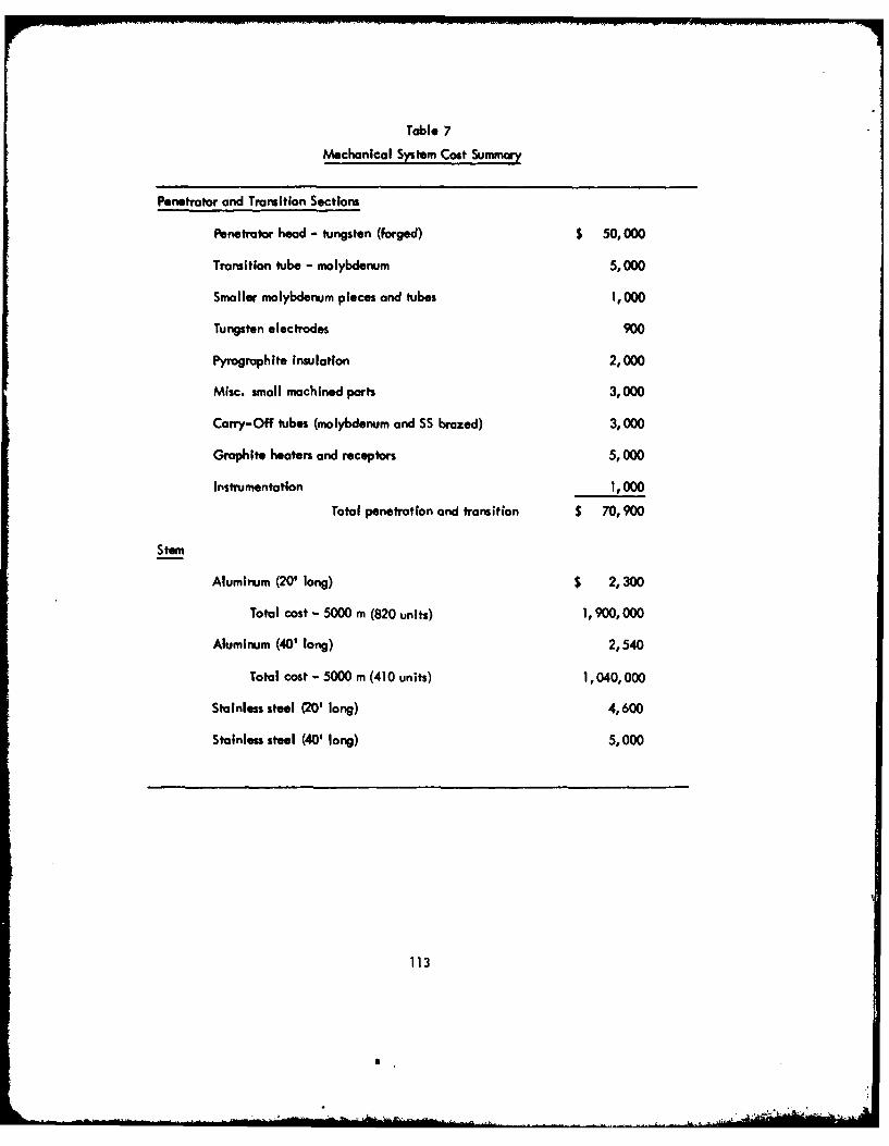
Table 7
Mechanical System Cost Summary
Penetrator and Transition Sections
Penetrator head - tungsten (forged) $ 50,000
Transition tube - molybdenum 5,000
Smaller molybdenum pieces and tubes 1,000
Tungsten electrodes 900
Pyrographite insulation 2,000
Misc. small machined parts 3,000
Carry-Off tubes (molybdenum and SS brazed) 3,000
Graphite heaters and receptors 5,000
Instrumentation 1,000
Total penetration and transition $ 70,900
Stem
Aluminum (20' long) $ 2,300
Total cost - 5000 m (820 units) 1,900,000
Aluminum (40' long) 2,540
Total cost - 5000 m (410 units) 1,040,000
Stainless steel (20' long) 4,600
Stainless steel (40' long) 5,000
113
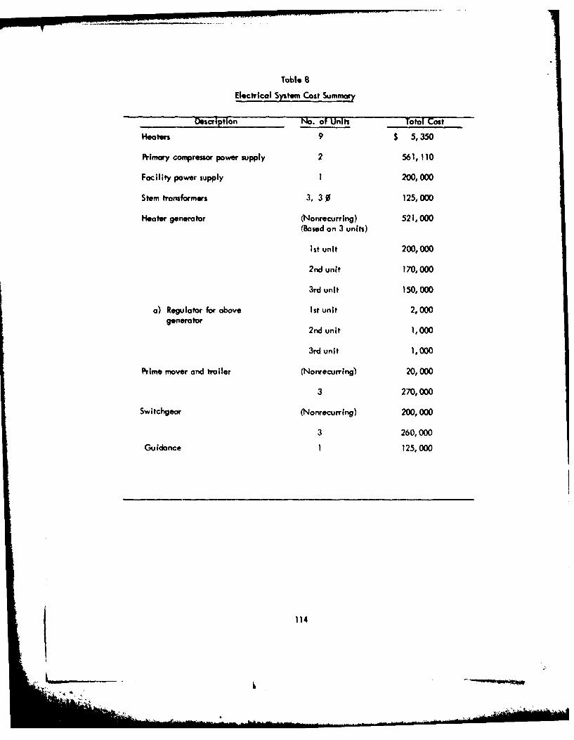
Table 8
Electrical System Cost Sumi.
Description No. of Units Total Cost
Heaters 9 $ 5,350
Primary conyressorpower supply 2 561,110
Facility power supply 1 200,000
Stem transformers 3, 30% 125,000
Heater generator (Nonrecurring) 521,000(Based on 3 units)
Ist unit 200,000
2nd unit 170,000
3rd unit 150,000
a) Regulator for above lIt unit 2,000generator 2dui ,0
2rd unit 1,000
Prime mover and trailer (Nonrecurring) 20,000
3 270,000
Switchgeor (Nonrecurring) 200,000
3 260,000
Guidance 1 125,000
114
PART VI: SELECTED PENETRATOR DESIGN
Mechanical and Structural
General
191. The selected earth melting penetrator configuration is illustrated in Figure 36.
Its present configuration represents the most recent development of the concept selected from
a number of arrangements developed earlier in the program and discussed in Part IV. The
most recent changes, made since the Bimonthly Progress Report of July 1, have been relative-
ly minor and have been mainly concerned with improving the flow path configurations for
the molten rock, the helium purge gas, and the air used to transport the removed rock. As a
result, the inerting of the heater cavities has been made much more positive and the flow area
available for the incoming transportation air has been substantially Increased. In addition,
the diameter of the split clamps used to joint stem sections has been Increased to present asmoother external configuration, and the complete inventory of power transformer sections is
now accommodated within one stem section. The design illustrated in Figure 35 incorporates
these latest changes.
Penetrator
192. The penetrator head is made of tungsten. Tungsten has been selected for its
high melting point of 3410°C, which is 800°C above that of molybdenum. High advance
rates required of the earth melting penetrator necessitate operation at the highest possible
temperatures. Actual operating temperatures, however, will probably have to be consider-
ably below these melting points. The melting points of tungsten-carbon eutectic and
moly-carbon eutectic, 271OC and 2200°C, respectively, represent more realistic ultimate
limits in view of the intimate contact between the penetrator head and graphite heater and
insulator components. The 500°C advantage possessed by tungsten should provide a strength
advantage for operation at the highest temperature levels. However, the corrosion/erosion
resistance of the tungsten in a molten rock environment may be inferior to that of molybdenum.
Experimental testing is needed to properly evaluate the relative merits of the materials.
115

For the purpose of the design study, the use of tungsten has been assumed. This selection
represents a conservative approach since the manufacturing problems associated with tungsten
are more severe than with others, like molybdenum.
193. Manufacture of the tungsten penetrator head involves the initial pressing and
and sintering of 92 percent derity blanks, which must then be further densifled by forging.
Since available press size is limited, the penetrator head will consist of laminations
diffusion bonded together. This concept was discussed with Northwest Industries of Albany,
Oregon who are familiar with this technology. This company has the capability of machin-
ing tungsten using single point tool methods and has worked In the LASL penetrator program.
In preliminary phone conversations, total cost of manufacturing a penetrator head was estimated
to be roughly $50, 000 for tungsten and $35, 000 for molybdenum. By way of comparison, on
estimate of $27,000 was obtained from Sylvania of Towanda, Pennsylvania, for a completely
machined 9-inch penetrator in 92 percent density tungsten (no final forging). However, the
strength of this material would almost certainly be inadequate.
194. The penetrator head has axial fins machined in its exterior surface. A large
diameter hole is machined along its centerline. The central hole accommodates inserted
tungsten, pyrographite, and molybdenum rings that together function as the core
former. The rings are held in position by a spring-loaded molybdenum tube and end ring.
Insulation tubes made of pyrolytic graphite ore interposed between the molybdenum tube and
the penetrator head to minimize the conduction of heat radially inward to the core.
195. Twelve hales are machined axially in the penetiator. Three of the holes are
equally spaced at 1200 intervals and provide a flow path for molten rock, from a circumferential
groove machined in the penetrator leading edge, to the rock nozzles of the three carry-off
tubes. The other nine holes are arranged in three equally spaced groups of three holes
between the rock flow holes and accommodate the nine resistance heaters.
196. Each resistance heater consists of a cylindrical stack of pyrographite and
graphite discs held in position by a compressive force transmitted through a spring loaded
tungsten electrode. The resistance heater is surrounded by a receptor cylinder of fine grain
graphite which is a close fit in the tungsten penetrotor head. An annular clearance space,
sufficiently large to prevent arcing, is maintained between the heater stack and its receptor.
Concentricity of the heater in its receptor is maintained by pilotting the heater in a
116
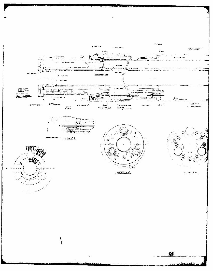
-. C
sp~,r CtA pet
* aT. ,vApe ~
§1' - <~> C- -~- ,-Z,-c~~L'~-~ -A- '~W
'IC ~A --
- '-I.
- ------- A ~ .,- - ---- ------.--- -'-'-C--- -
~4. VttC.,qe -C- wfnC etOflflS~o0fl
PC ~ j-; -~*~i~'i "LI ~'~<C-C-~~ 8 __
- -~ ~----- p -r
-- ___ P C-~ Lt2~-~tft-, ---C-
..I
sped PC ~rre .:.'44fl 40tCS neT, TCAGSTTh A - Cp,,gCtc TO DM54 _______
eflet (P rh-a~P COtCePRS)
9 tWO t~%t TRA TOt Ito PCCPCJ 'ID
-'p ~
(-'5.'
"~'IC'eR* '~ 5g~T~Q~J C C ~.---P -*~~#. I; .4-.- -2/ /<
I -----C--.---
A ~ 'c~lip. ... C-,-
- 4;~-e' 2 (N
SECTiON 4-4 ~FCTTOCJ ~ 8
I'
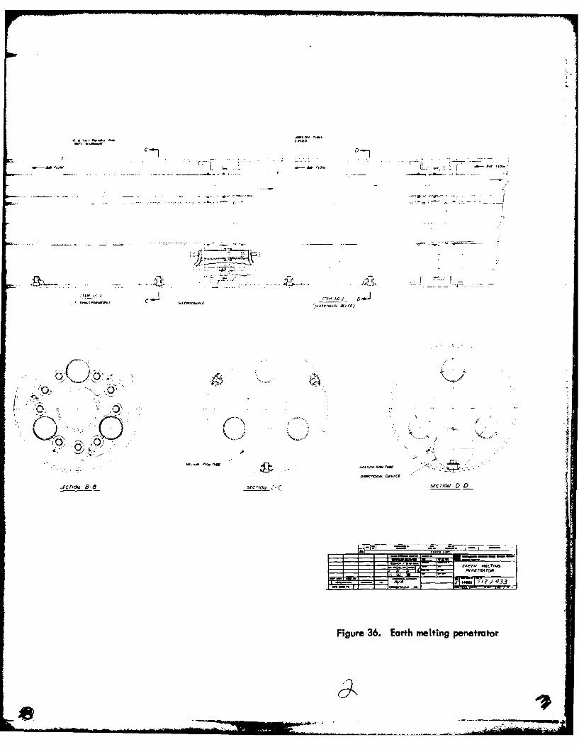
* ~1A~~~ -S Uj
cf 00 2~~
a.- 4a "OWIL -. a- 4
*~~~~A~ TrlltnS MQfccoc
04177 ?CAA 4rc3)
Fiur 36 athmlin Qstao
- -MA
machined receptacle at the leading edge of the penetrator. Concentricity of the tungsten
electrode is maintained by a boron nitride insulator bushing that locates the electrode
and that, in turn, is supported in a molybdenum ring located in the molybdenum transition
tube assembly which forms the tungsten penetrator to the stem.
197. The transition tube assembly consists of a molybdenum tube of sufficient length
to provide the necessary thermal isolation of the stem from the penetrator. A short length of
threaded tube joins the transition tube to the penetrator head and serves to minimize heat
conduction to the transition tube. A pyrographite ring transfers compressive force to the
penetrator from the transition tube and limits heat transfer, while another ring inside the
transition tube also serves to limit heat transfer to the stem. A series of rings made of
tungsten, graphite, and molybdenum around the transition tube where it joins the penetrator
head function as a hole former. The transition tube is joined, at the end remote from the
penetrator, by means of a split ring and ring nut arrangement to a stainless steel end fitting.
The end fitting provides for the attachment of the adjacent stem section by means of a split
clamp arrangement, and accommodates insulation bushings that locate the heater electrodes.
The end fitting also supports the termination of the carry-off tubes. That portion of the end
f;tting not required structurally is machined away to provide a flow path for the air flowing
along the stem to the carry-off tube entrances.
198. Each carry-off tube consists of an inner stainless steel tube, extending From the
rock nozzle to the transition end fitting, and a shorter molybdenum outer tube joined .o it
through a spiral wire. The spiral wire forms a spiral passageway along which the air enters
the carry-off tube. At the rock nozzle, the air enters the inner diameter of the carry-off
tube at high velocity, impinging on the molten rock and breaking it up into small particles.
The air then transports the rock particles along the carry-off tube to the portal.
199. Three thermocouples are accommodated in drilled holes in the penetrator head,
one to aach 1200 sector. This number represents an absolute minimum and will probably have
to be increased to achieve the necessary control reliability. The thermocouple leads terminate
at the transition endfitting in a miniature connector that allows the lead to be continued
through the stem sections to a control box at some suitable bcation. The control box modulates
power to the penetrator sectors in accordance with the requirements of the guidance system
and thermocouples.
119

200. Helium gas is fed to the heater cavities of the penetrator head through a single
small-diameter line with sealed connectors at each stem joint. The helium enters one of the
heater cavities from the delivery tube and flows along the heater periphery toward the
penetrotor leading edge. The helium then enters a machined groove connecting the heater
cavity to a circumferential groove turned in one of the laminations prior to the diffusion
bonding process. The circumferential groove conveys the inerting helium to the other heater
cavities. The helium is ultimately exhausted into the transition region.
201. No particular problems are foreseen in the manufacture of the transition
components since similar components have been fabricated for the LASL penetrator pogrom.
202. Required length of the transition section has not yet been determined. The use
of a stainless steel stem section immediately adjacent to the transition would probably allow
its length to be minimized. The possible alternative arrangements need to be investigated
from a heat transfer standpoint and the best arrangement selected.
Stem
203. The stem consists of an assembly of standard stem sections joined end to end by
split clamps. Specially modified stem sections accommodate transformer modules, guidance
equipment, and control boxes. Standard stem sections from which mast of the stem length is
constructed are made of aluminum. The stem section immediately adjacent to the penetrator
and transition section may be made of 18-8 stainless steel to provide improved temperature
capability.
204. The standard stem section is fabricated from standard sizes of extruded
aluminum pipe. An outer casing, of 10. 75-in.-diameter x 0. 200-in.-thick pipe is welded
at each end to a machinedi aluminum end fitting. The end fittings are machined to provide
support for a central 3.5-in.-diameter x 0. 120-in.-thick pipe and three 1. 9 0 0 -in.-diameter
x 0. 065-In. -thick pipes equally spaced around the central pipe. The three smaller pipes
carry the particulate rock and transport air to the portal. The larger central pipe accommo-
dates the rock core. Rubber O-rings are used to seal the smaller tubes to the end fittings and
to seal the stem sections to each other.
205. The end fittings also provide support for nine male and female electrical connectors
three thermocouple connectors and the connectors for the single helium line. The electrical
convertors provide electrical continuity for the nine wires of the three separate three-phase
circuits. The nine wires traverse the length of the stem section andare bolted to female connectors
at one end and male connectors at the other end of the stem. The connectors permit simple
120

plug-in connection of stem to stem. The connectors are supported from the end fittings in
insulating bushings made of some suitable plastic material. It should be noted that the
wires between the transformer modules and the penetrator head carry low voltage-high
amperage current while the wires between the transformer modules and the portal carry high
voltage-low amperage current. The nine transformer modules are arranged in groups of three
between the three carry-off tubes of a single stem section. Each group of three modules is
constructed as a single 3. 25-in. -diameter tube supported from the outer casing of the stem
through brackets welded to the transformer and bolts inserted from the outside of the stem.
206. The end fittings are machined away, wherever possible, (whileproviding the
necessary support for connectors, etc. ) to provide the largest possible flow path area for the
incoming air. Incoming air flows from the portal to the penetrator head in the spaces inside
the outer casing and outside the central pipe. The returning air, transporting the rock
particles, travels to the portal inside the three smaller tubes. Pressure drop in the air causes
the outer casing to be stressed in tension and the central pipe and three smaller pipes to be
compressively loaded. Maximum hoop stresses are experienced at the portal and, as
presently designed, the stem is capable of withstanding an air pressure at entry of approximately
500 psi. This capability could be increased by the use of pipes of thicker section that would,
in turn, increase the weight of the stem and, as a consequence, the required thrust force.
207. Axial compressive stresses in the stem outer wall resulting from the propulsion
force, estimated to be approximately 69, 000 Ib, are approximately 10, 000 psi. No stress or
stability problems are anticipated to result from propulsion forces.
208. Each stem section is estimated to cost approximately $2300 if made in a 20-ft
length. Thus, total stem cost for a 5000-meter hole would be roughly $1, 900, 000. If the
stem is made in 40-ft lengths, the cost per section would increase to $2540 and the total
cost for a 5000 -meter hole would be reduced to approximately $1, 000, 000. The longer stem
lengths are obviously preferable from the standpoints of both cost and pressure drop. However,
the cost and performance advantage must be considered in relation to the inconvenience of
transporting and handling the longer sections. It may be possible to make a case for several
design "weights. " Light section, short lengths could be used for short holes with progressively
heavier and longer sections for long holes. A cost summary of the penetrator head and stem
components is given in Part V. The hardware costs for a 5000-meter hole appear to be
121
dominated by the stem costs. Moreover, at least 80 percent of the stem cost is incurred in
the machining of end pieces and connector details. A detailed manufacturing engineering
study would appear to be warranted before proceeding further into the detail design phases
to attempt to reduce machining costs. The small pieces such as electrical connectors can be
considered high production items (3650 items for the 40-ft stem design) and could probably
justify the procurement of some production tooling.
Propulsion module
209. A propulsion module concept is illustrated in Figure 37. The design employs acircumferential sleeve that can grip the wall of the hole through an inflatable boot and be
propelled along the stem in either direction by a system of ball screw jacks. The propulsion
module, thus, has the capability of propelling the stem in the melting direction while the
gripping mechanism is energized. At the end of its travel, the Inflatable boot is deflated and
the gripper sleeve is rapidly returned to its starting position to repeat its gripping and
propulsion cycle. Propulsion modules are planned for use in pairs, both units driving together
but returning separately to hold position. However, the mode of operation is flexible and
can be varied to suit the particular conditions encountered. Modules could be used singly
at regular intervals along the stem or in pairs at widely separated locations. When used in
pairs, some separation of the two units may be beneficial in traversing unconsolidated rock
formations.
210. Three ball screw jacks are employed to exert the propulsive force and areevenly spaced around the annulus between the inner and outer diameters of the stem section
between the carry-off tubes. The largest possible ball screw jacks, consistent with the space
limitations, ar employed to achieve the maximum thrust capability. For the purpose of
developing a properly sized and potentially practical design, the ball scew nuts were selected
from the Saginaw catalog. * A 2. 000 BCD unit with a lead of 0. 265 in. and 10-1/2 turns of
balls was stated to have an operating load capability of 11,502 lb for 1, 000, 000 inches of
operating life. This operating life is representative of about five holes 5000 meters in length.
Thus, the three screw jacks working together have a thrust capability of 34, 506 lb, and two of
the propulsion modules working together should be capable of exerting a propulsive force of
69, 000 lb. This is approximately equal to the force required to overcome the friction
• The particular units used in the design were obtained from the listing of CTS custom threadball bearing screw assemblies given on page 2 of Section A-3 of the Saginaw catalog.
122
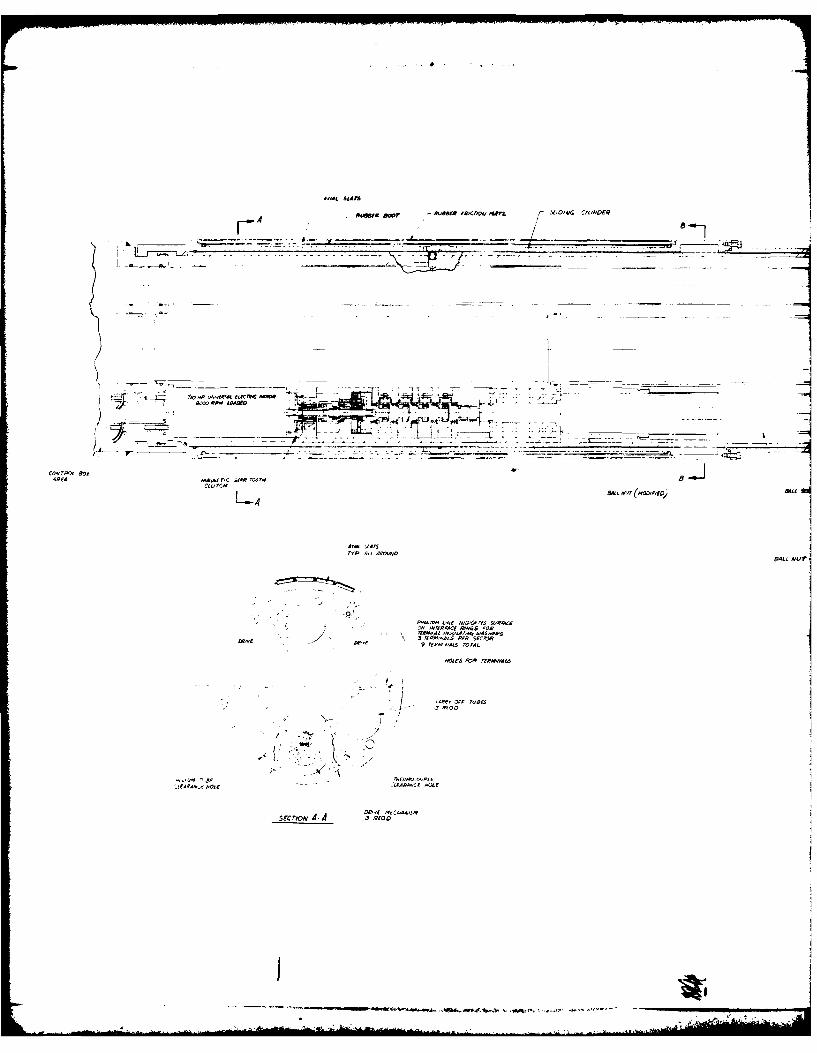
4"-1 SiAIs
ARewa aw7 - we~' I&,IdS10 AWL F eow crs40FAF
___ T__ rm. ___ -
L4 B~ ar BidSgf
L-4i
still
Q. P-mM IsIS c.~ res Weirdc
3/i P,,SS Pt15es~
se*i~ >5 JPIC
Ar
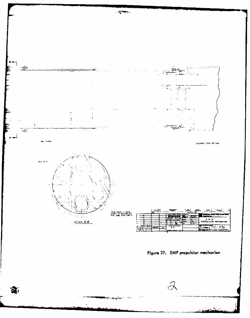
.4'
_r Ix
-f----~
j
-,Z- ,T'2 J 4
Fiue3.EM rplioJehns
"mom",I

(assuming i = 0.25) exerted by the weight of 5000 meters of stem and the contained
rock core.
211. The thrust of the ball screw is transmitted to the stem through a stack of fiveduplex 62-mm-OD x 25 -mm-ID x 17 -mm-wide ball bearings. The stacked configurationresults in a load capacity of the stack approximately three times that of a single bearing, onthe basis of the life of the first bearing to fall, and provides sufficient life, based on
bearing minimum life, to form three 5000-meter holes.
212. The ball screw is driven, through a five-stage planetary reduction gear, by a1/10 HP universal electric motor. Four of the stages drive in through the sun gear and outthrough the planet carrier, the annulus gear being fixed. The reduction ratio of each stageis four for a total reduction of 256. The fifth, high speed stage has a 3:1 ratio and drives in
through the sun and out through the annulus gear, the planet carrier being fixed. Thus, when
driving through this gear, the direction of rotation is reversed and the overall reduction ratio
is 768. This gear ratio is used when propelling the penetrator and, under these conditions,
the universal motor generates its full power at approximately 8000 rpm. The ball screw is
then turned at approximately 10. 4 rpm, a speed calculated to produce an advance rate of
about 1. 15 mm/'sec, leaving some margin to allow time for return of the slider.
213. The electric motor drives the reduction gear through a quillshaft whose axial
position is controlled by a magnetic actuator. Axial motion of the quillshaft allows it to
disengage the motor drive from the sun gear of the three-stage reduction/reversing gear and
drive directly into the four-stage fixed annular gear set. Under these conditions, the
direction of rotation is reversed and the overall reduction ratio is reduced from 768 to 256.This mode of operation is used to return the sliding gripper boot to its original position after
the completion of a driving cycle. Under these conditions, the universal motor is relatively
unloaded and its operating speed increases to about three times its unloaded rpm. This
speed increase, together with the three-fold reduction in gear ratio, returns the slider in
about 11 percent of the time taken in the driving direction. Thus, the time required to return
the slider does not form a substantial portion of the operating time and is essentially com-
pensated for by a small excess of operatingspeedunder load. (1. 15 mm/sec versus 1 mn/sec
design goal).
214. The electrical connections to the universal motors are made in the form of
male and female plug components to allow easy connection of the propulsion module to a
125
special stem section containing the appropriate control boxes. Provision must also be made
in the connector area to provide continuity for the main EMP power supply cables, helium
line, and instrumentation. All of these details have not been worked out on Figure 36 because
of time limitations, but no particular problems are anticipated in accommodating them.
215. The ball screw nut transmits its driving force to a beam whose outer ends engage
with a groove turned in the inside diameter of the slider. The beam ends pass through axial
slots machined in the outer diameter of the stem. The straight beam allows the large ball
screw load to be transmitted to the slider without imposing any bending moment on the ball
screw. The offset moment in this arran-gement is carried internally by the straight beam.
216. The slider member is extended axially beyond the groove to carry O-ring seals
that engage the stem beyond the extremities of the axial slots. Thus, the stem remains
hermetically seoali4 despite the drive mechanism and slots.
217. High pressure air is supplied to the space between the slider and stem between
a pair of O-rings that move with the slider but are separated such that they alwavs straddle
the supply port. Thus, movement of the slider in no way interferes with the air supply. A
drilled passage in the stem is led to a plug connector which engages with a similar device
in the special stem section accommodating the control box. In this manner, high pressure
air, tapped from the air flowing in the stem annulus. is fed to the slider pneumatic gripper
boot when demanded by the control system.
218. The gripper boot consists of an assembly of axial slats inserted into circum-
ferential grooves at each end of the slider. The slats carry rubber friction material on their
outer surfaces. A continuous rubber tubular member, sealed to the slider at each end, is
used to energize the gripper boot. When the high pressure air is admitted to the space
inside the rubber tubular member, it expands, forcing the slats to move outward and grip
the wall of the hole. The frictional propulsive force is transmitted along the slats, as
compressive force, to the slider and from the slider to the screw jacks.
219. The length of gripper boot engaged with the hole wall must be sufficient to
transmit the propulsive force without overloading the glass hole liner. If the limiting tensile
strength of the glass liner is assumed to be 2000 psi, the allowable radial pressure is 130 psi
(assuming a liner thickness of 0.39 inch). Approximately 8 inches of gripper boot length
are required to transmit the 34, 500-lb propulsive force, asstiming a coefficient of friction
126
of I. In the design illustrated in Figure 37, approximately 24 inches of gripper length
have been provide4 permitting coefficients of friction below 1 or radial pressures below
130 psi. It is envisaged that the control system would employ a pressure reducing valve to
ensure that the pressurizing air pressure is held safely below the fracturing pressure of the
glass liner (130 psi).
Electrical
Heaters
220. The penetrator will be powered from nine heaters placed in three groups of
three heaters each. Each heater group is powered from one three-phase transformer whose
secondary winding is wired to a wye configuration. One heater is terminated between one
phase to neutral of the transformer secondary. To provide a total heating capacity from
I to 1. 5 MW, it is suggested that a prototype heater be fabricated and tested to insure that
the power requirements per heater and the helium pressure established for the required heater
voltage can be achieved. This would clarify the discrepancies defined in Part IV,
Electrical System. The heater would be fabricated from discs of pyrolytic graphite and fine
grain graphite. Various configurations of disc combinations would be tested to achieve the
power required.
221. The thermal expansion of the heaters must also be considered. As shown in
Table 5, the temperature coefficient of pyrolytic graphite in the C plane is 13 x 106 / F.
If the entire heater length of 10 inches were made of pyrolytic graphite, then the thermal
expansion for a maximum of 5000F would be:
Thermal expansion - 13 x 10- 6 in.. (10 in. ) (5000°F)in. 0 F
0.65 inches
222. The thermal expansion of the heater as well as the tungsten electrode is
accommodated as shown In Figure 36. A spring is used to force the electrode to the heater
and maintain compression of the heater discs. As the heater expands, the spring Is compressed
127
I
and the mating portion of the electrode Is driven Into the power Inlet connector. Sufficient
space in the mating connector is provided for maximum system expansion. The tungsten
electrode is insulated from system common with boron nitride sleeves.
223. The pyrolytic heater discs are available from Pfizer; the fine grain graphite
discs from Ultra Carbon or Pure Oil; pyro sleeves from Ultra Carbon; tungsten electrodes
from Sylvania.
Stem transformer
224. As was indicated in Part IV, Electrical System, the stem section to house
the transformers using a 60-Htz power system would be approximately 180 feet long. Before
decisions could be made to power the heaters with a higher frequency source, an investiga-
tion was made into the availability of higher frequency generators (Port IV, Stem
Transformer).
225. By using a power source frequency of 680 Hz, the overall transformer
stem length could be reduced from 180 ft to 30 ft. By using a 30-ft section, the transformer
stem section would be compatible with the entire system stem lengths for ease of shipment
and minimum coolant pressure losses through the stem end plates. The transformer primary
and secondary would be wound around micra-laminations. The transformer would be made
up of small sections about 15 in. long and 3. 25 in. in diameter. Each of these small
sections would be stacked in series like cells in a flashlight until the proper operating
voltages were required for the primary. All of the secondaries would be connected in
parallel to a common bus for that phase. Three such transformer stacks would be connected
primary delta - secondary wye for a three-phase system for three heaters. Three three-phase
transformers would be required for the nine heaters. As with the heaters, it is recommended
that a single phase of the transformer be built and tested to verify the transformer design.
The transformer design is available from Westinghouse.
Power transmission
226. It is suggested that a minimum wire size of AWG No. 6 be used for the
transmission line. To allow for the maximum cross-sectional area within a given stem section
for coolant flow, cable insulation material used on the transmission wire should be con-
sidered. The overall cable diameter can be reduced by using "Kapton' as an insulating
1 |

material over the cable conductors. "Kaptan" is a DuPont product and several cable
manufacturers produce cables with "Kapton" Insulation.
Power supply
227. Figure 33 shows a typical mobile substation. All trailers used within this
system shall contain outline lights and reflectors that comply with applicable highway regula-
tions of the Interstate Commerce Commission. It is expected that all equipment mounted on
trailers for this system will meet the vehicle size and weight limits for all 50 states. Only
two areas pose a potential problem for road clearance. These are the District of Columbia
and the state of West Virginia. These two areas define their maximum clearances at 12.5
feet. Should the final design of equipment fall within this limit, the equipment could be
used in these two areas also.
228. As indicated in the discussion of stem transformers, a power frequency of
680 Hz will be used for this system to reduce the stem transformer size as well as other
auxiliary equipment. Generators to provide the power requirements for this system at 680 Hz
are expected to be 18 inches in diameter and 48 inches long with on estimated weight of
1600 pounds. To produce this frequency, the generators may have to be turbine driven.
A number of suppliers of the prime mover include the following: Stewart and Stevenson
Services, Inc.; AVCO, Lycoming Engine Group; AiResearch; Solar International; and
General Electric.
229. Of the above, Stewart and Stevenson is the most experienced for this appl ica-
tion and has the capability for handling the power supply system, including trailer mounting.
The generator is available from Westinghouse and involves only a modification to a unit
being built for the Navy.
230. Since the heater power supply system is to operate at 680 Hz, a separate
power supply would be required for facility needs. These include power for lighting (indoor
and outdoor), fans, pump motors, convenience outlets, power tools, compressors, trailers
to house personnel, cooking facilities, heating and air conditioning, welding machines, etc.
It is expected that the vast majority of facility power will be required to operate the
primary compressor for the stem coolant. Compressor power requirements can be in the
range of 1 MW. To provide for power supply failures, two units of the type shown in
Figure 33 will be required for the compressor. Figure 38 shows a typical unit that would
129
ftffI. L
14
130
be required for the rest of the facility. Although the figure shows two units, it is expected
that only one unit would be required. If the smaller unit were to fail, it would be possible
to tap into the compressor power supply temporarily. The smaller unit is suggested for
the rest of the facility since there will be times when the process is not operational, and
It would not be practical to run the large unit for facility needs alone. Diesel fuel can
be provided from standard fuel hauling trailers. The facility water supply could also be
provided by water carrying trailers. Figure 39 shows the system block diagram for the entire
facility.
Thermot/Hydrulic
Power and temperature
231. Power and temperature were calculated for the reference design configura-
tion in all geologic models using the same techniques as described in Part IV, System
Performance Analysis. The maximum power requirement of 909 kW is shown in Figure 40
for the CALCI model at 1. 39 mnVsec (5 nvhr) velocity. Of this, 303 kW appears as
chemical energy in the evolution of CO 2 and 73 kW is lost to the surrounding rock. For
the MASIG calculation, there are no chemical reactions and the maximum amount of heat
input is 685 kW, of which up to 600 kW can be recovered in the air coolant stream.
232. The calculated surface temperature of the penetrator is given in Figure 41
for all five models. As described in Part IV, the temperature calculation is subject to the
significant uncertainty associated with the unknown liquid thermal conductivity. In
general, temperatures are less than those of Figures 12 and 13 since the design configura-
tion is a finned surface providing more than 60 percent greater heat transfer surface area
than the simple planar surfaces of those figures. The maximum temperature at 1. 39 mm/sec
of 2800 K (4580°F) in UNCON is still excessive, because of the low thermal conductivity
of the model. Increasing the length of the penetrator substantially reduces the temperature
by up to 300 K as shown by the dotted line for UNCON in Figure 41.
233. A two-dimensional heat transfer model of the circular cross section of the
earth melting penetrotor tungsten head was developed. The current model version shown in
Figure 42 is equipped with only 38 nodes* to minimize the complexity of the problem and to
* Heat transfer analyses commonly use several hundred nodes.
131
I rl" C u - r c K
---. I------r-----
- - - - -- - - - - - - -
-e-
Fiue3. ytmboc igI13
I;~p I ~7in
0
2L2
00
*1...
4e4
hIL
C"4
z
D Jr-
I a E
1I *
.>.2'42 2
'4 00
C4 0 &
Z 0
04 04C-C*
1344
accelerate the acquisition of results. The purpose of analyses with this model is to provide
a two-dimensional reference temperature distribution prediction for the current conceptual
EMP design.
234. The first calculations have been completed using the Figure 42 model.
The material nodes (1 through 38) were assumed to be tungsten having a constant thermal
conductivity of 20 BTU/hr ft 0 F. Nodes 9, 12, 13, 16, 19 and 20 model the penetrator
heaters. They have been assigned volumetric heat generation rates of 1.26 BTU/in. 3-secto simulate penetrator operation at 0. 10 MW. Calculations performed with this preliminary
model confirm earlier hand calculations, which indicated that large radial-direction temp-
erature differentials could exist in the penetrator as currently designed. Under the assumed
boundary conditions, which are noted in Figure 42, nodes 1 and 38 are the points of highest
and lowest tungsten temperature, respectively. For the heat generation rate and material
property conditions identified above, the predicted temperature difference between those
nodes was 1890°F. This differential is clearly unacceptable considering the low penetrator
power level applied in the calculations. These preliminary results are being reported here
to identify a potential thermal problem in the current EMP design and to note that detailed
two-dimensional heat transfer analyses of the penetrator have been initiated. Improvements
and refinements planned for the heat transfer model will increase the number of material
nodes, account for heut transfer to the undisturbed core region, permit temperature-
dependent material properties, model the cylindrical shape of the penetrator heaters and
melt removal tubes more effectively, etc. Future thermal analyses w;Ill employ the model
to further assess the adequacy of the penetrator design and to evaluate potential design
modifications.
Air coolant supply
235. The purpose of the air coolant supply is threefold: provide coolant for
Internal parts (e.g., guidance package); cool the glass liner until it becomes self supporting;
and provide floatation for extrudite cooling and removal.
236. In the requirements definition, air was specified as the preferred coolant,
water was less desirable because of its potential I1mited availability at the drilling site,
and other coolants such as pure nitrogen which has zero site availability in quantities
135
00
z 0LU L&U Lj
Ca. cr -elU
49I
c2n
44)
136
needed. Calculations to determine the amount of air needed and the piping pressure drops
were made. The coupled energy/momentum solution for counterflow streams of air overthree miles long is Indeed complex. For the conceptual design of this report, scoping
calculations were made to Identify problem areas.
237. Assuming the maximum allowable pipe temperature is 4000F for the alum-
inum stem configuration, and the maximum power which can be extracted of 600 kW as
explained In the previous section, the maximum air flow requirement is approximately
8 ib/sec (6300 SCFM). For the flow of water at pressures greater than 250 psia, only
2 Ib/sec (14 gpm) is needed. If steel pipes were used, air flow rates of 3 to 4 lb/sec could
be used because of higher allowable material temperatures.
238. Pressure drop calculations were made to determine feasibility of supplying
this quantity of air to the end of a 5000 m hole. In most of the following calculations,
Incompressible flow equations were assumed, and make the results applicable only to small
pressure drops. A series of steps are necessary to complete the evaluation, the first being
the wall friction pressure drop in the pipe.239. For the fl,/DH friction losses down the stems to the penetrator tip (5000
meters), pressure drop can be calculated by
2 f. W2-.
where
f - Fanning friction factor, unitless
L - total length of penetrator, in.
DH - hydraulic diameter, In.
W - coolant flow rate, lb/sec 2Ib m in.2
gc - gravitation constant, lb . i.
s
P - average density of coolant, lb/In. 3
A F - stem flow area, in. 2
6Pf - friction pressure drop down stem, lb f/in. 2
137
The hydraulic diameter by definition is
4 AFDH
where
W. P. - wetted perimeter, in.
For the current penetrator design
AF =A AR~A - A
where
A - Solid cross-sectional area stem - 83. 3 In. 2
s
AR - Cross-sectional area of 3 coolantreturn pipes - 8.5 in. 2
AW - Cross-sectional area of helium flowtube and nine power wires - 0. 5 in.
A - Cross-sectional area of core - 9.6 In. 2
AF 64.7 in. 2
and
W.P. = w(D +3 D + D + D) (4)
where
D - Respective pipe or wire outside diameter.
Therefore
D-= 4 Ila =3.8 in.DH 68.7
240. The Fanning friction factor above was estimated based
on using a hydraulic Reynolds number calculated by
ReH HR H -
where
W equals coolant flow rate.
138
swum
241. For air and water coolant flows of 2 -- 16 lb/sec, ReH numbers were
0.5 x i05-.-8 x 10⁵. Using a roughness Factor of-O. 004, Fanning Friction factors were
of the order of -0. 005.
242. The overall total penetrator stem length for the fL/DH calculation above Is
L < 5000 meters or 1.97 x 105 in.
243. Substituting the above parameters, the total stem friction pressure drop
down to the penetrator tip as a function of coolant flow and density is
P =3.2x 10⁻⁴
244. Figure 43 shows the stem pressure drop using this equation. For air flow
of 8 lb/sec at an average of 300F and 500 psia, the pressure drop is only 20 psi.245. In the reference EMP design, the penetrator stems are connected in series.
Each stem length is 20 ft long and has a support plate at each interface. There are 820
interfaces for the maximum 5000 meter length. The purpose for these plates is twofold:
a To give structural rigidity to the stem section.
b To support the weight of the retractable core, coolant/debrisreturn pipes and power lines.
246. To allow for coolant flow down to the penetrator tip, each support platehas 35 flow holes. As a result, there are a significant number of contraction and expansion
flow losses. Since the thickness of these plates is small compared to the upstream and down-
stream flow diameters, a sharp-edged orifice loss calculation is made to conservatively
estimate the total pressure drop for 820 plates.
247. The pressure drop across one plate is
139
R c:,
C- ~( -i
CD
Cw%.
u 4;
Lu:~ IaL-
#A'
/I -l P 11400
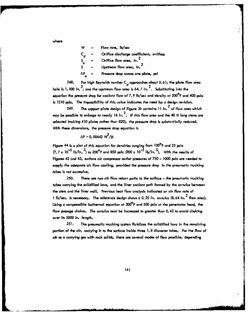
where
W - Flow rate, lb/sec
C - Orifice discharge coefficient, unitlessd2S - Orifice flow area, in. 2
S - Upstream flow area, in. 2
AP - Pressure drop across one plate, psi0
248. For high Reynolds number Cd approaches about 0.61; the plate flow area
hole is 1. 100 In. ; and the upstream flow area is 64.7 in. . Substituting into the
equation the pressure drop for coolant flow of 7. 9 lb/sec and density at 2000F and 400 psia
is 1510 psla. The impossibility of this value Indicates the need for a design revision.
249. The support plate design of Figure 36 contains 11 In. 2 of flow area which2may be possible to enlarge to nearly 18 in. . If this flow area and the 40 ft long stems are
selected (making 410 plates rather than 820), the pressure drop is substantially reduced.
With these dimensions, the pressure drop equation is
AP = 0. 00442 W2/p
Figure 44 is a plot of this equation for densities ranging from 100F and 25 psia
(7.7 x 10- 5 lb/in. 3) to 200°F and 850 psla (200 x 10- 5 lb/in. 3). With the results of
Figures 42 and 43, surface air compressor outlet pressures of 750 - 1000 psla are needed to
supply the adequate air flow cooling, provided the pressure drop in the pneumatic mucking
tubes Is not excessive.
250. There are two air flow return paths to the surface - the pneumatic mucking
tubes carrying the solidified lava, and the liner coolant path formed by the annulus between
the stem and the liner wall. Previous heat flow analysis Indicated an air flow rote of
1 lb/sec. is necessary. The reference design shows a 0.25 in. annulus (8.64 In. 2 flow area).
Using a compressible Isothermal equation at 3000F and 500 psla at the penetrator head, the
flow passage chokes. The annulus must be increased to greater than 0. 43 to avoid choking
over its 5000 in. length.251. The pneumatic mucking system fluldizes the solidified lava In the remaining
portion of the air, carrying it to the surface Inside three 1. 8 diameter tubes. For the flow of
air as a carrying gas with rock solids, there are several modes of flow possible, depending
141
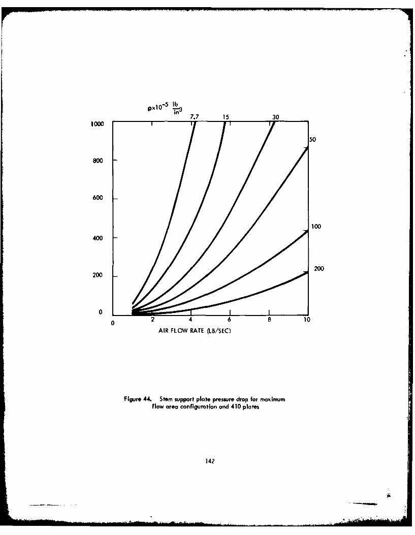
PO-5 l -b
,37.7 15 301000
50
800
600
100
400
200200
0J
0 2 4 6 8 10AIR FLOW RATE (LB/SEC)
Figure 44. Stem support plate pressure drop for maximumflow area configuration and 410 plates
142
depending upon the density of the rock solids, solids-to-air weight ratio and air velocity. With
low-density rock solids, or low solids-to-air ratios, and high air velocities, the solids may
be fully suspended and fairly uniformly dispersed over the return pipe cross section. In a
horizontal pipe with low solids-to-air ratios and low air velocities, the solids may bounce
along the bottom of the pipe. With high solids-to-air ratios and low air velocities, the
rock solids may settle to the bottom of the pipe and form dunes with the rock particles
moving from dune to dune (Reference 10).
252. Assuming a minimum penetration rote of 5 nV1Ar and a cylindrical
melt-out of the rock material, the solid mass flow rate for granite is 0.64 lb/sec. Using an
air flow rate of 7.9 Ib/sec, the solid-to-air weight ratio is 0.08 for granite. These are
very low ratios compared to those used in conventional pneumatic conveying. In practice,
the actual conveying velocities used in systems with low solids-to-gas weight-rate ratios
(< 10), i.e. conventional pneumatic conveyors (References 11 and 12, are generally over
50 ft/sec. The air coolant velocity Is - 170 ft/sec which is more than ample to convey
small particles of rock material. For high solid-to-gas weight-rate ratios (> 50), the
actual gas velocities used are generally less than 25 ft/sec and are approximately equal to
twice the actual solids velocities (Reference 10).
253. For low rock solids-to-air weight ratio, the minimum carrying velocity
can be estimated by the following equaton proposed by Dalla Vale (Reference 13),
based on conveying tests with particles less than 0. 32 in. in size. Using air as the
carying gas:
Vc 2 s
wherev - Minimum carrying velocity, ft/sec
ps - Density of the solids particles, lb/ft3
D S - Diameter of largest particle to be conveyed, ft
254. The density of granite is approximately 186 Ib/ff3 respectively. From
the above equation, for particles as large as 0. 32 in. the minimum carrying velocity
required Is 48 ft/sec.
143
.. .. .. . ..... . .. . .... ... . .... . .. .. . . .... -,,, ...... .. . , . .-- .-: . ' ...
255. For one return pipe, the minimum carrying mass flow rate Is therefore
W =Apv c PA
whome
A - cross-sectional flow area of a return pipe, ft2
PA - average density of air In return pipe, lb/ft3
W - minimum carrying mass flow rote for air, lb/sec
Cc
256. The total minimum air mass flow needed for all three return pipes is
2. 19 lb/sec at the average density of air used in the return pipe for conditions of
- 225 psia and -25 0°F.
257. For upflow of gases and solids in vertical pipes, the minimum carrying
velocity for low solids-to-gas weight-rote ratios can be estimated by the following equation
proposed by Dalla Valle in Reference 13:
=910 .s D51. 60
vc Ps + 62.3
258. Substituting values for granitic rock material and using a particle diameter
of 0. 32 Inches gives 78 ft/sec.
259. In Reference 15 for low solid-to-gas weight-rate ratios less than 10,
vG - vs in a vertical pipe is about equal to the free fall terminal velocity of the particles.
Also, in Reference 15 for the case of spherical particles, the terminal velocity can be
calculated by 0.5vt 4 g D P G)
3 C
where C - drag coefficient, dimensionless
PG - gas density
260. In Reference 15, a plot is presented of crag coefficient versus Reynolds
number. In the Newton's Law region which covers the Reynolds-number range of 1000 to
200,000 drag coefficient C has an approximately constant value of 0. 4 for spherically shaped
particles. For a particle diameter of 0.32 Inches, the terminal velocity is 25 ft/sec.
144

261. The above fluidization requirement Is less than the thermal requirement
needed for solidification. A pressure drop analysis of 7.9 lb/sec air flowing in three tubes
of 1.8 in. diameter Indicates that the flow Is choked for pressure levels of 1000 psi*,
the highest pressure level considered reasonable for this application.
262. A number of conclusions can be drawn from the preceding air flow
calculations. Up to 8 lb/sec of air or 2 lb/sec of water is needed to solidify the molten
rock before the fluidized mucking system con remove It. Within the present geometric
constraints of 12 in. diameter and a 3 mile hole, the water pressure drop and pressure level
(to prevent boiling) are not a problem since only 500 psia pump pressure is required. The air
flow pressure requirement is substantially different, that is, there is Insufficient flow area
at reasonable pressure levels to provide 7.9 lb/sec. The engineering solutions to this
problem are not Immediate. A more detailed analysis of the coupled heat transfer/pressure
drop relationships Including compressible flow with heat exchange between the caunterflow
air streams, the drill string and the glass liner could show a lower flow rate and area require-
ment.
263. If the 8 lb/sec is still required and the flow area Is Insufficient after a more
sophisticated analysis, the remaining options are water cooling or a change In the more con-
straining requirements. For example, an increase in allowable diameter to 14 in. would
provide nearly double the available flow area. These desigrVrequirement trade-off sequences
must be addressed in the first period of a preliminary design phase.
145
4'i

PART VII: DEVELOPMENT PROGRAM
264. With the completion of the Phase I Conceptual Design Study of an Earth
Melting Penetrator to be used as a geoprospecting tool, the details of subsequent phases
can be prepared. The development program consists of three more phases spanning the next
5 fiscal years and is depicted in Figure 45.
Phase If - Prototype Penetrator Demonstration
265. The objective of Phase 11 is to demonstrate a prototype penetrator in the field.
The penetrator, consisting of the penetrator body, heaters, transformers, and associated
hardware to permit field demonstration of the "hat end" of the system, will Ibe designed and
two assemblies fabricated. Operational performance will be evaluated through demonstration
of penetration rate; hale and core formation; response to guidance through differential heating;
starting, stopping, and retraction evaluations; general compatibility of the penetrator with
earth; and internal electrical, thermal, cooling, and extridite removal.
Tasks associated with this phase include:
Task I Heater Tests
Task 2 Penetrator Design
Task 3 Penetrotor Fabrication and Assembly
Task 4 Field Test Plan
Task 5 Field Tests
Task 6 Program Management and Integration
266. The objectives of these tasks are as follows:
Task I - heater tests
267. A heater will be fabricated, based on the conceptual design of Phase I and
the detailed design of Task 2, to verify satisfactory heater performance. The heater will be
assembled into a refractory body and the completed test assembly used to melt earth
146
4
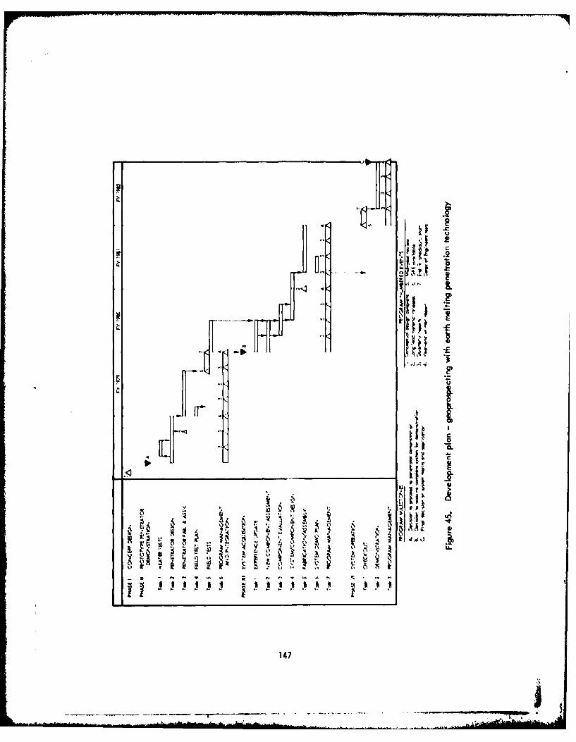
U
~IL.
L
~ I
~r. Li I;~ii *1~ I.
9. ~ A~~;
~dU..~ ~i U ..3 ~
0,1.Jt LI0
IN IN 4 -' NI j . IN EN 4 En NE ~ ~ EN IN
I- I'- I'- a111111 *.Ijj j *~ ~ II
147

material, simulating the heat sink and demonstrating compatibility of the refractory body
with the earth.
Task 2 - penetrator design
268. Detailed design of the prototype penetrator as previously described will be
the objective of Task 2. Specifications of field support equipment recommended for
government supply will be developed and will Include such Items as those required to
supply electrical power, fluids, and gases to the penetrator.
Task 3 - penetrotor fabrication and assemby
269. Work in Task 3 will Involve procurement, fabrication and assembly of the
hardware designed in Task 2.
Task 4 - field test plan
270. In Task 4, details of the test phase will be developed. Included will be test
sequence logic and procedures far operation of the penetrator.
Task 5 - field tests
271. During Task 5, field test demonstrations will be performed. A test checkout
will be performed at Westinghouse prior to delivery to the Corps of Engineers. This test
will require some government supplied equipment. It is recommended that the Corps of
Engineers cooperate in this test as part of its orientation to penetrator operation. The
penetrator will then be turned over to the Corps of Engineers for evaluation with technical
assistance from Westinghouse. In addition, an evaluation of logging Instruments can be
performed in glass-lined holes and compared with performance in conventional holes upon
request by the Corps of Engineers.
Task 6 - program management and Integration
272. Task 6 provides program administration details such as schedule and cost
monitoring, progress reports, and customer Interface. In addition, technical integration
Is Included to assure that the penetrotor design requirements remain consistent with the
overall system requirements of the fallow-on phases and that technical Integration with
the government supplied equipment for the field tests is maintained.
14i8
273. This phase represents a significant step in earth melting penetrator technology
because of the scale-up from Los Alamos feasibility experiments. The time span is 2-1/4
years, with the effort divided between these years to satisfy fiscal year funding constraints.
To maintain reasonable costs while achieving the field testing stage, LASL experience,
off-the-shelf components or adaptation of same, and a restricted development effort will
be employed. While the level of confidence is still conbidered acceptable, this approach
does introduce some risk to the program in that the penetrator assembly involves high
technology and is best evaluated as an assembly. At this point, the risk incurred is
anticipated in the area of achieving specific design performance objectives such as
penetration rate. Experimental results derived from performance demonstration may be used
to update design in subsequent phases.
274. At a logical program decision point near the end of Phase II, continuation
or termination of the program can be considered and determined.
Phase III - System Acquisition
275. The objective of Phase III is the acquisition of a complete system for
checkout and field demonstration in Phase VI. This effort, of course, assumes a successful
Phase II program and the decision to proceed. Current plans envision the following tasks
as appropriate to Phase II:
Task I Experience Update
Task 2 New Component Assessment
Task 3 Component Evaluation
Task 4 System and Component Design
Task 5 Fabrication and Assembly
Task 6 System Demonstration Plan
Task 7 Program Management
276. Objectives of these tasks are detailed in the Following paragraphs.
Task I - experience update
277. The design and experimental experience obtained from Phase II penetrator
tests will be factored into an updated design of the penetrator to improve performance.
149

Task 2 - new component assessment
278. Components not involved in the Phase II program will be evaluated prior
to their Integration into the design. Components such as guidance, control, and grippers
are in this category. It is anticipated that some test evaluations in the next task will
be required as a result of these assessments.
Task 3 - component evaluations
279. Component tests to evaluate critical parameters of components resulting
from Task 2 assessments and from Phase II test results are included here. Effects of a
"hostile" environment on a guidance component, electrical circuit, or material are
candidate areas for evaluation.
Task 4 - system/component design
280. During this task, the system design will be completed. Components of the
system will be designed or specifications prepared for procurement. The designed and
procured components will be interfaced and integrated. Additional government support
equipment beyond that determined in Phase II will be specified. This task should
benefit significantly from the penetrator design effort of Phase I.
Task 5 - fabrication and assembly
281. During this task, the system will be fabricated, procured, and assembled
and assembly test performed to ready the system for operational tests in Phase VI.
Task 6 - system demonstration plan
282. A System Demonstration Plan will be required to define the test plan
objectives and sequence logic of tests. Included will be procedures for the operation of
the penetrator system.
Task 7 - program management
283. This task will provide the program supervision and customer contact for
technical, schedule, and cost control and reporting.
284. The output of this phase will be one complete geoprospecting EMP system
and selected spare parts for use in Phase VI. This phase is shown in Figure 42 to span
2 years.
150
!A-i - I- o

Phase IV - System Operation
285. Phase IV is the test phase for the hardware acquired In Phase III. Its
relationship to the total program Is shown in Figure 45 and Is expected to be 1 year in
duration consisting of the following tasks:
Task 1 Checkout
Task 2 Demonstration
Task 3 Program Management
286. Objectives of these tasks are detailed in the following paragraphs.
Task I - checkout
287. Task I Involves a brief test program conducted by Westinghouse at the
Corps of Engineers site to check out the initial operation of the system and procedures.
It is expected to consist of an Integrated test with Corps of Engineers personnel to insure
orderly transfer of equipment and provide training.
Task 2 - demonstration
288. Task 2 is an extended test period under the direction of the Corps of
Engineers with technical support from Westinghouse. It, in fact, represents the significant
system demonstration to which the total program has been directed. Demonstration is to
take the form of a prototype field operation to prove the worthiness of the technology for
geoprospecting applications.
Task 3 - program management
289. Task 3 provides the program supervision and customer contact for technical,
schedule, and cost control and reporting as well as source engineering support for the
Corps of Engineers field demonstrations.
290. At the end of Phase IV, another logically scheduled program milestone will
allow for a decision regarding the deployment of the earth melting penetrator (EMP)
as a geoprospecting system.
151
__

Estimated Contract Resources
291. The estimated resources by phase and task and by fiscal year are presented
in Table 9. The costs are estimated based on 1977 dollars, do not Include escalation, and
should therefore be considered approximate.
152
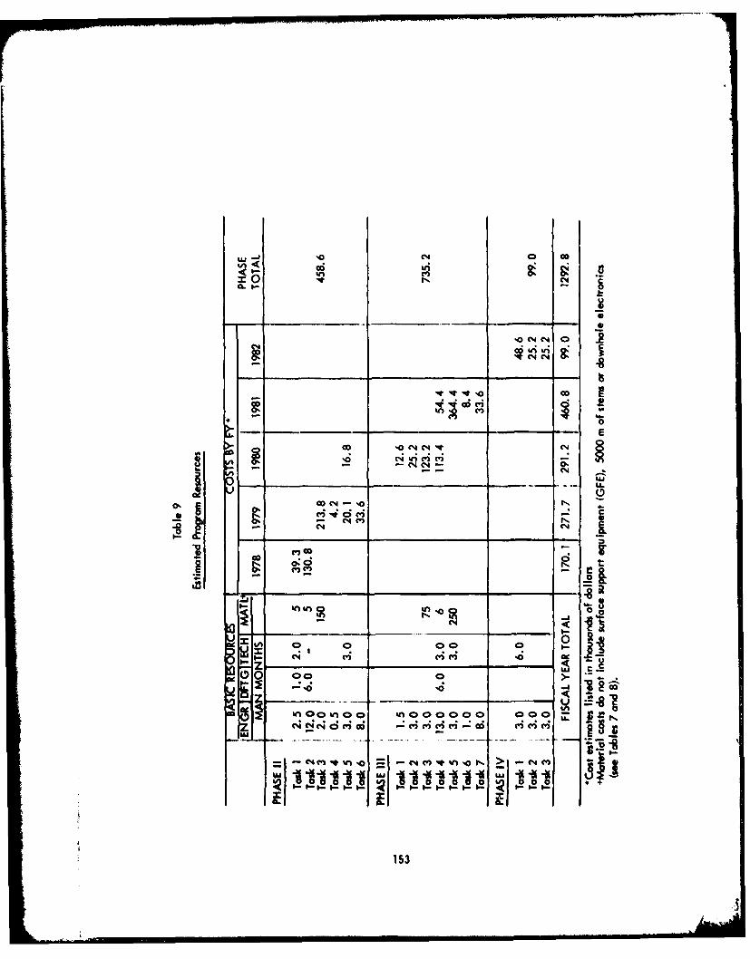
mn4 Go
,n 8
0
___ - E
'ONN CIC
2 to m
(4 C4a
'U
- ________ ________ . .
O~~ E ~C 4
Z .6 0 0 m
0 0
'0
~'0 '0
00l 1U91 liia.
%n cc n a o 153 00 0 oC%; 4 'q d(4 i C- riC4 i - ca -i -i i L
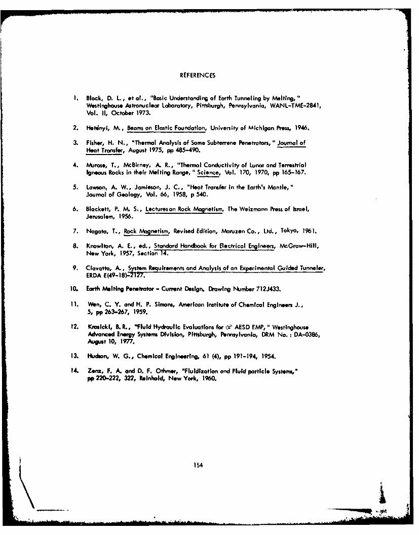
REF ERENC ES
1. Black, D. L., et al., "Basic Understanding of Earth Tunneling by Melting,Westinghouse Astronuc lear Laboratory, Pittsburgh, Pennsylvania, WAN L-TME-2841,Vol. 11, October 1973.
2. H"tnyI, M., Beams on Elastic Foundation, University of Michigan Press, 1946.
3. Fisher, H. N., "Thermal Analysis of Some Subterrene Penetrators, " Journal ofHeat Transfer, August 1975, pp 485-490.
4. hIvjrase, T., McBirney, A. R., "Thermal Conductivity of Lunar and TerrestrialIgneous Rocks in their Melting Range. " Science, Vobl. 170, 1970, pp 165-167.
5. Lawson, A. W., Jamieson, J. C., "Heat Transfer In the Earth's Mantle,"Journal of Geology, Vol. 66, 1958, p 540.
6. Blackett, P. M. S., Lectureson Rock Magnetism, The Weizmann Press of Israel,Jerusalem, 1956.
7. Nagata, T., Rock Magnetism, Revised Edition, Maruzen Co., Ltd., Tokyo, 1961.
8. Knowlton, A. E., ed., Standard Handbook for Electrical Engineers, McGraw-Hill,New York, 1957, SectionT 14.
9. Ciovatta, A., System Requirements and Analysis of an Experimental Guided Tunneler,ERDA E(49-18)Z2127.
10. Earth Melting Penetrator - Current Design, Dr'awing Number 712J433.
11. Wetn, C. Y. and H. P. Simons, American Institute of Chemical Engineers J.,5, pp 263-267, 1959.
12. Krosicki, B. R., "Fluid Hydraulic Evaluations for 0i' AESD EMP, " WestinghouseAdvanced Energy System DivIsion, Pittsburgh, Pennsylvania, DRM No. : DA-0386,August 10, 1977.
13. Hudson, W. G., Chemical Engineering, 61 (4), pp 191-194, 1954.
14. Zenz, F. A. and D. F. Othmer, "Fluidization and Fluid particle Systemns,"
pp 220-222, 322, Reinhold, Now York, 1960.
154
Kli
15. Dalao Val.e, Heating, Piping Air Conditioning, 4, pp 539-641, 1932.
16. Hinkle, H., Ph. D Thesis, Chemical Engineering, Georgia Institute of Technology,
Atlanta, 1953.
17. Perry, I. H., "Chemical Engineers Handbook," 4th od., McGrant Hill Co.,NeWw Yorkc, 1963.
155
In accordance with letter from DAEN-RDC, DAEN-ASI dated22 July 1977, Subject: Facsimile Catalog Cards forLaboratory Technical Publications, a facsimile catalogcard in Library of Congress MARC format is reproducedbelow.
Black, D LFeasibility study of an earth melting penetrator system
for geoprospecting tunnel right-of-ways / by D. L. Black,Westinghouse Advanced Energy Systems Division, .Large, Penn-sylvania. Vicksburg, Miss. : U. S. Waterways Experiment Sta-tion ; Springfield, Va. : available from National TechnicalInformation Service, 1978.
155 p. : ill. ; 27 ca. (Technical report - U. S. ArmyEngineer Waterways Experiment Station ; S-78-17)
Prepared for Office, Chief of Engineers, U. S. Army, Wash-ington, D. C., under Contract No. DACW 39-76-C-0163.
References: p. 154-155.
1. Drilling. 2. Earth melting penetrators. 3. Feasibilitystudies. 4. Geophysical exploration. 5. Penetration. 6. I',,.trators. 7. Right of way. 8. Rock melting penetrators.9. Soil penetration. 10. Subsurface exploration. 11. Tunnels.12. Underground openings. r. United States. Army. Corps ofEngineers. II. Westinghouse Electric Corporation. AdvancedEnergy Systems Division. III. Series: United States. WaterwaysExperiment Station, Vicksburg, Miss. Technical report ; S-78-17.TAT.W31 no-S-7R-17
Ai


![[PPT]Teledyne-ODI Template - HOME « Institute of Nuclear …vlvnt09/parallel_slides/mudge... · Web viewHermetic Penetrator – Need photo of the hermetic penetrator Customer and](https://img.pdfslide.net/doc/110x75/5aaf6d997f8b9a07498d5134/pptteledyne-odi-template-home-institute-of-nuclear-vlvnt09parallelslidesmudgeweb.jpg)


![Cloud penetrator-hakin9-review -march-2012]](https://img.pdfslide.net/doc/110x75/55549a0ab4c905fd608b45d1/cloud-penetrator-hakin9-review-march-2012.jpg)