Embed Size (px)
Citation preview
9-31
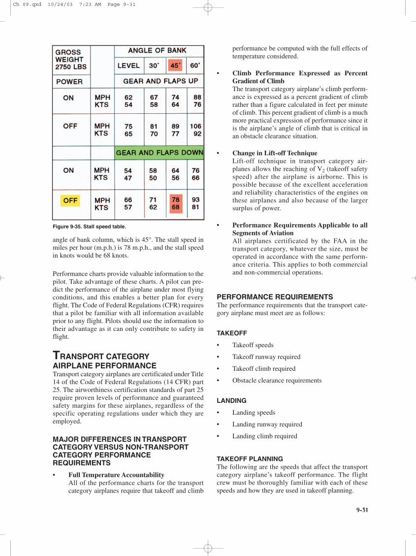
angle of bank column, which is 45°. The stall speed inmiles per hour (m.p.h.) is 78 m.p.h., and the stall speedin knots would be 68 knots.
Performance charts provide valuable information to thepilot. Take advantage of these charts. A pilot can pre-dict the performance of the airplane under most flyingconditions, and this enables a better plan for everyflight. The Code of Federal Regulations (CFR) requiresthat a pilot be familiar with all information availableprior to any flight. Pilots should use the information totheir advantage as it can only contribute to safety inflight.
TRANSPORT CATEGORYAIRPLANE PERFORMANCETransport category airplanes are certificated under Title14 of the Code of Federal Regulations (14 CFR) part25. The airworthiness certification standards of part 25require proven levels of performance and guaranteedsafety margins for these airplanes, regardless of thespecific operating regulations under which they areemployed.
MAJOR DIFFERENCES IN TRANSPORTCATEGORY VERSUS NON-TRANSPORTCATEGORY PERFORMANCEREQUIREMENTS
• Full Temperature AccountabilityAll of the performance charts for the transportcategory airplanes require that takeoff and climb
performance be computed with the full effects oftemperature considered.
• Climb Performance Expressed as PercentGradient of ClimbThe transport category airplane’s climb perform-ance is expressed as a percent gradient of climbrather than a figure calculated in feet per minuteof climb. This percent gradient of climb is a muchmore practical expression of performance since itis the airplane’s angle of climb that is critical inan obstacle clearance situation.
• Change in Lift-off TechniqueLift-off technique in transport category air-planes allows the reaching of V2 (takeoff safetyspeed) after the airplane is airborne. This ispossible because of the excellent accelerationand reliability characteristics of the engines onthese airplanes and also because of the largersurplus of power.
• Performance Requirements Applicable to allSegments of AviationAll airplanes certificated by the FAA in thetransport category, whatever the size, must beoperated in accordance with the same perform-ance criteria. This applies to both commercialand non-commercial operations.
PERFORMANCE REQUIREMENTSThe performance requirements that the transport cate-gory airplane must meet are as follows:
TAKEOFF
• Takeoff speeds
• Takeoff runway required
• Takeoff climb required
• Obstacle clearance requirements
LANDING
• Landing speeds
• Landing runway required
• Landing climb required
TAKEOFF PLANNINGThe following are the speeds that affect the transportcategory airplane’s takeoff performance. The flightcrew must be thoroughly familiar with each of thesespeeds and how they are used in takeoff planning.
Figure 9-35. Stall speed table.
Ch 09.qxd 10/24/03 7:23 AM Page 9-31
9-32
All of the above V speeds should be considered duringevery takeoff. The V1, VR, V2 and VFS speeds should bevisibly posted in the cockpit for reference duringthe takeoff.
Takeoff speeds vary with airplane weight. Before take-off speeds can be computed, the pilot must first deter-mine the maximum allowable takeoff weight. The threeitems that can limit takeoff weight are runway require-
ments, takeoff climb requirements, and obstacle clear-ance requirements.
RUNWAY REQUIREMENTSThe runway requirements for takeoff will be affectedby the following:
• Pressure altitude
• Temperature
• Headwind component
• Runway gradient or slope
• Airplane weight
The runway required for takeoff must be based uponthe possible loss of an engine at the most critical point,which is at V1 (decision speed). By regulation, the air-plane’s takeoff weight has to accommodate the longestof three distances:
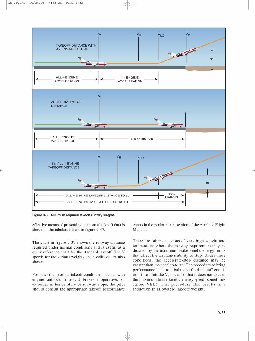
1. Accelerate-Go DistanceThe distance required to accelerate to V1 with allengines at takeoff power, experience an enginefailure at V1 and continue the takeoff on theremaining engine(s). The runway requiredincludes the distance required to climb to 35 feetby which time V2 speed must be attained.
2. Accelerate-Stop DistanceThe distance required to accelerate to V1 with allengines at takeoff power, experience an enginefailure at V1, and abort the takeoff and bring theairplane to a stop using braking action only (useof thrust reversing is not considered).
3. Takeoff DistanceThe distance required to complete an all-enginesoperative takeoff to the 35-foot height. It must beat least 15 percent less than the distance requiredfor a one-engine inoperative engine takeoff. Thisdistance is not normally a limiting factor as it isusually less than the one-engine inoperative take-off distance.
These three required takeoff runway considerations areshown in figure 9-36.
BALANCED FIELD LENGTHIn most cases, the pilot will be working with a per-formance chart for takeoff runway required, which willgive “balanced field length” information. This meansthat the distance shown for the takeoff will include boththe accelerate-go and accelerate-stop distances. One
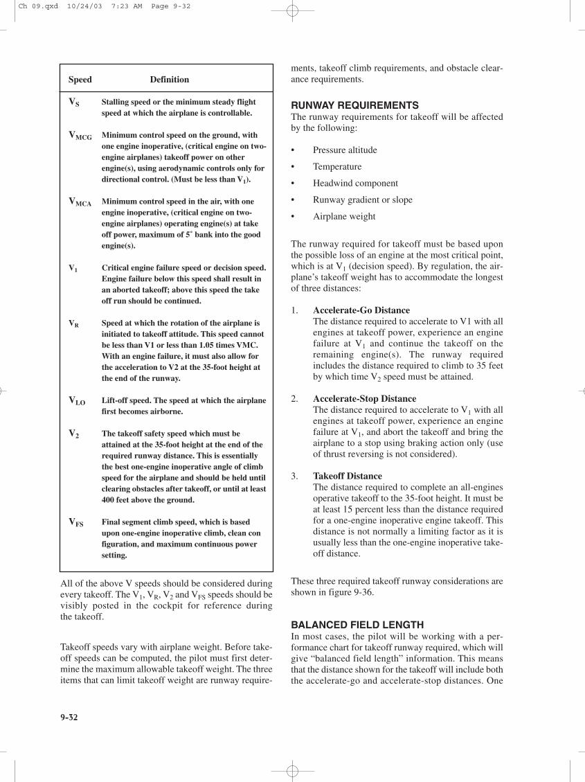
Speed Definition
VS Stalling speed or the minimum steady flight speed at which the airplane is controllable.
VMCG Minimum control speed on the ground, with one engine inoperative, (critical engine on two-engine airplanes) takeoff power on other engine(s), using aerodynamic controls only for directional control. (Must be less than V1).
VMCA Minimum control speed in the air, with one engine inoperative, (critical engine on two-engine airplanes) operating engine(s) at takeoff power, maximum of 5˚ bank into the good engine(s).
V1 Critical engine failure speed or decision speed.Engine failure below this speed shall result in an aborted takeoff; above this speed the takeoff run should be continued.
VR Speed at which the rotation of the airplane is initiated to takeoff attitude. This speed cannot be less than V1 or less than 1.05 times VMC. With an engine failure, it must also allow for the acceleration to V2 at the 35-foot height at the end of the runway.
VLO Lift-off speed. The speed at which the airplanefirst becomes airborne.
V2 The takeoff safety speed which must be attained at the 35-foot height at the end of the required runway distance. This is essentially the best one-engine inoperative angle of climb speed for the airplane and should be held until clearing obstacles after takeoff, or until at least400 feet above the ground.
VFS Final segment climb speed, which is based upon one-engine inoperative climb, clean configuration, and maximum continuous power setting.
Ch 09.qxd 10/24/03 7:23 AM Page 9-32
9-33
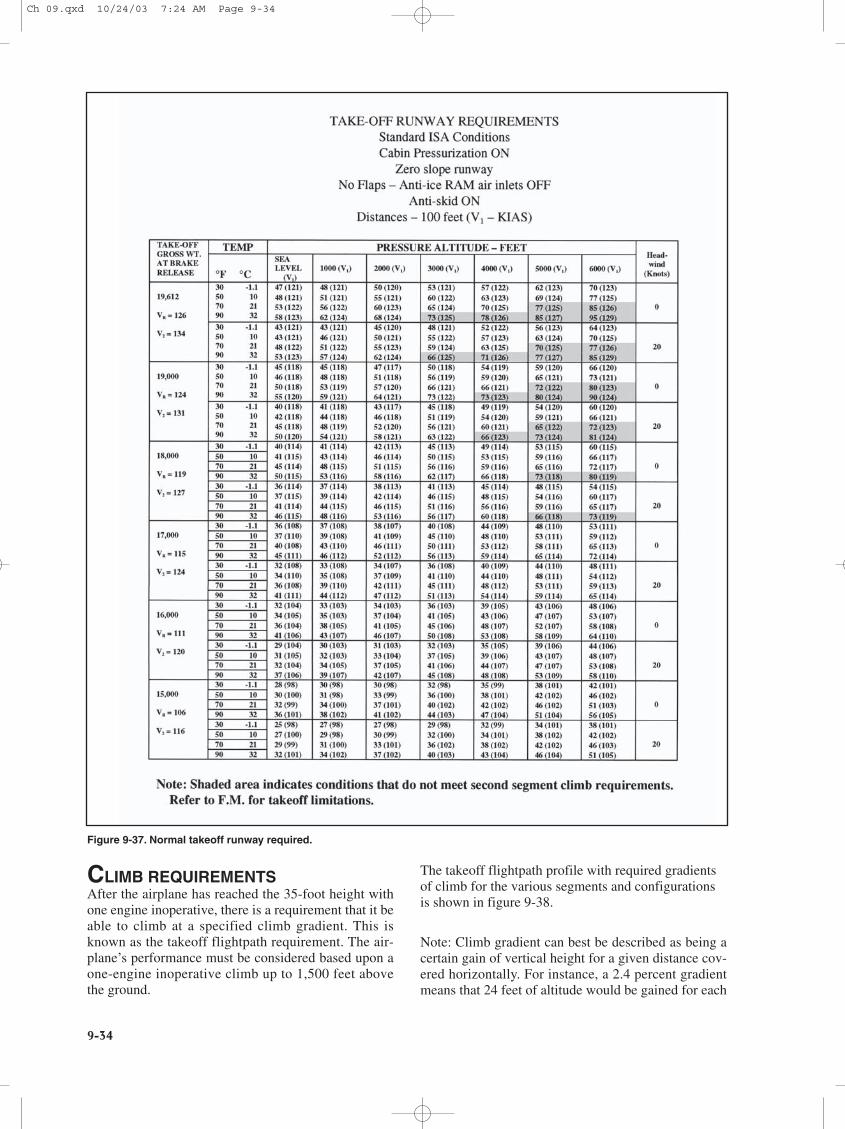
effective means of presenting the normal takeoff data isshown in the tabulated chart in figure 9-37.
The chart in figure 9-37 shows the runway distancerequired under normal conditions and is useful as aquick reference chart for the standard takeoff. The Vspeeds for the various weights and conditions are alsoshown.
For other than normal takeoff conditions, such as withengine anti-ice, anti-skid brakes inoperative, orextremes in temperature or runway slope, the pilotshould consult the appropriate takeoff performance
charts in the performance section of the Airplane FlightManual.
There are other occasions of very high weight andtemperature where the runway requirement may bedictated by the maximum brake kinetic energy limitsthat affect the airplane’s ability to stop. Under theseconditions, the accelerate-stop distance may begreater than the accelerate-go. The procedure to bringperformance back to a balanced field takeoff condi-tion is to limit the V1 speed so that it does not exceedthe maximum brake kinetic energy speed (sometimescalled VBE). This procedure also results in areduction in allowable takeoff weight.
TAKEOFF DISTANCE WITHAN ENGINE FAILURE
V1 VR VLO V2
35'
1– ENGINEACCELERATION
ALL – ENGINEACCELERATION
V1
ALL – ENGINEACCELERATION
ACCELERATE/STOPDISTANCE
STOP DISTANCE
V1 VR VLO
35'
ALL – ENGINE TAKEOFF DISTANCE TO 35' 15%MARGIN
ALL – ENGINE TAKEOFF FIELD LENGTH
115% ALL – ENGINE TAKEOFF DISTANCE
Figure 9-36. Minimum required takeoff runway lengths.
Ch 09.qxd 10/24/03 7:23 AM Page 9-33
9-34
CLIMB REQUIREMENTSAfter the airplane has reached the 35-foot height withone engine inoperative, there is a requirement that it beable to climb at a specified climb gradient. This isknown as the takeoff flightpath requirement. The air-plane’s performance must be considered based upon aone-engine inoperative climb up to 1,500 feet abovethe ground.
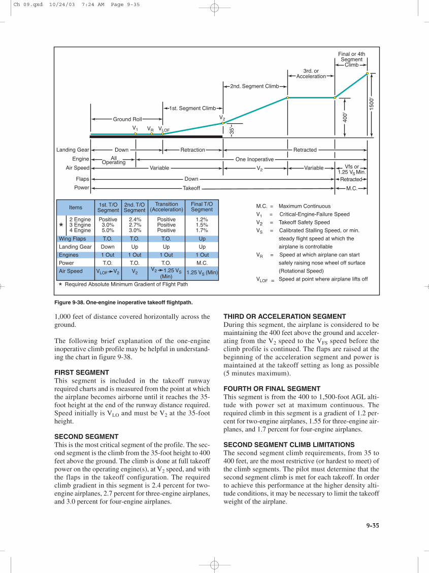
The takeoff flightpath profile with required gradientsof climb for the various segments and configurationsis shown in figure 9-38.
Note: Climb gradient can best be described as being acertain gain of vertical height for a given distance cov-ered horizontally. For instance, a 2.4 percent gradientmeans that 24 feet of altitude would be gained for each
Figure 9-37. Normal takeoff runway required.
Ch 09.qxd 10/24/03 7:24 AM Page 9-34
9-35
1,000 feet of distance covered horizontally across theground.
The following brief explanation of the one-engineinoperative climb profile may be helpful in understand-ing the chart in figure 9-38.
FIRST SEGMENTThis segment is included in the takeoff runwayrequired charts and is measured from the point at whichthe airplane becomes airborne until it reaches the 35-foot height at the end of the runway distance required.Speed initially is VLO and must be V2 at the 35-footheight.
SECOND SEGMENTThis is the most critical segment of the profile. The sec-ond segment is the climb from the 35-foot height to 400feet above the ground. The climb is done at full takeoffpower on the operating engine(s), at V2 speed, and withthe flaps in the takeoff configuration. The requiredclimb gradient in this segment is 2.4 percent for two-engine airplanes, 2.7 percent for three-engine airplanes,and 3.0 percent for four-engine airplanes.
THIRD OR ACCELERATION SEGMENTDuring this segment, the airplane is considered to bemaintaining the 400 feet above the ground and acceler-ating from the V2 speed to the VFS speed before theclimb profile is continued. The flaps are raised at thebeginning of the acceleration segment and power ismaintained at the takeoff setting as long as possible(5 minutes maximum).
FOURTH OR FINAL SEGMENTThis segment is from the 400 to 1,500-foot AGL alti-tude with power set at maximum continuous. Therequired climb in this segment is a gradient of 1.2 per-cent for two-engine airplanes, 1.55 for three-engine air-planes, and 1.7 percent for four-engine airplanes.
SECOND SEGMENT CLIMB LIMITATIONSThe second segment climb requirements, from 35 to400 feet, are the most restrictive (or hardest to meet) ofthe climb segments. The pilot must determine that thesecond segment climb is met for each takeoff. In orderto achieve this performance at the higher density alti-tude conditions, it may be necessary to limit the takeoffweight of the airplane.
Landing Gear
Engine
Air Speed
Flaps
Power
Down Retraction Retracted
Retracted
AllOperating One Inoperative
Vfs or1.25 VS Min.
Variable VariableV2
VLOFVRV1
V2
Down
Takeoff M.C.
400'
1500
'
35'
Items 1st. T/OSegment
2nd. T/OSegment
Transition(Acceleration)
Final T/OSegment
2 Engine3 Engine4 Engine
Positive3.0%5.0%
PositivePositivePositive
2.4%2.7%3.0%
1.2%1.5%1.7%
Wing Flaps
Landing Gear
Engines
Power
Air Speed
T.O.
Down
1 Out
T.O.
VLOF V2
T.O.
Up
1 Out
T.O.
V2
T.O.
Up
1 Out
T.O.V2 1.25 VS
(Min)
Up
Up
1 Out
M.C.
1.25 VS (Min)
*
* Required Absolute Minimum Gradient of Flight Path
M.C. = Maximum Continuous
V1 = Critical-Engine-Failure Speed
V2 = Takeoff Safety Speed
VS = Calibrated Stalling Speed, or min.
steady flight speed at which the
airplane is controllable
VR = Speed at which airplane can start
safely raising nose wheel off surface
(Rotational Speed)
VLOF = Speed at point where airplane lifts off
Ground Roll
1st. Segment Climb
2nd. Segment Climb
3rd. orAcceleration
Final or 4thSegment
Climb
Figure 9-38. One-engine inoperative takeoff flightpath.
Ch 09.qxd 10/24/03 7:24 AM Page 9-35
9-36
It must be realized that, regardless of the actualavailable length of the takeoff runway, takeoffweight must be adjusted so that the second segmentclimb requirements can be met. The airplane maywell be capable of lifting off with one engine inoper-ative, but it must then be able to climb and clearobstacles. Although second segment climb may notpresent much of a problem at the lower altitudes, atthe higher altitude airports and higher temperaturesthe second segment climb chart should be consultedto determine the effects on maximum takeoffweights before figuring takeoff runway distancerequired.
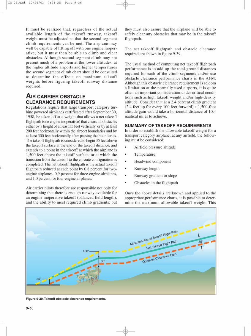
AIR CARRIER OBSTACLECLEARANCE REQUIREMENTSRegulations require that large transport category tur-bine powered airplanes certificated after September 30,1958, be taken off at a weight that allows a net takeoffflightpath (one engine inoperative) that clears all obstacleseither by a height of at least 35 feet vertically, or by at least200 feet horizontally within the airport boundaries and byat least 300 feet horizontally after passing the boundaries.The takeoff flightpath is considered to begin 35 feet abovethe takeoff surface at the end of the takeoff distance, andextends to a point in the takeoff at which the airplane is1,500 feet above the takeoff surface, or at which thetransition from the takeoff to the enroute configuration iscompleted. The net takeoff flightpath is the actual takeoffflightpath reduced at each point by 0.8 percent for two-engine airplanes, 0.9 percent for three-engine airplanes,and 1.0 percent for four-engine airplanes.
Air carrier pilots therefore are responsible not only fordetermining that there is enough runway available foran engine inoperative takeoff (balanced field length),and the ability to meet required climb gradients; but
they must also assure that the airplane will be able tosafely clear any obstacles that may be in the takeoffflightpath.
The net takeoff flightpath and obstacle clearancerequired are shown in figure 9-39.
The usual method of computing net takeoff flightpathperformance is to add up the total ground distancesrequired for each of the climb segments and/or useobstacle clearance performance charts in the AFM.Although this obstacle clearance requirement is seldoma limitation at the normally used airports, it is quiteoften an important consideration under critical condi-tions such as high takeoff weight and/or high-densityaltitude. Consider that at a 2.4 percent climb gradient(2.4 feet up for every 100 feet forward) a 1,500-footaltitude gain would take a horizontal distance of 10.4nautical miles to achieve.
SUMMARY OF TAKEOFF REQUIREMENTSIn order to establish the allowable takeoff weight for atransport category airplane, at any airfield, the follow-ing must be considered:
• Airfield pressure altitude
• Temperature
• Headwind component
• Runway length
• Runway gradient or slope
• Obstacles in the flightpath
Once the above details are known and applied to theappropriate performance charts, it is possible to deter-mine the maximum allowable takeoff weight. This
400'
35'
35'
Minimum Actual Takeoff Flight Path
Net Takeoff Flight Path
Obstacle Clearance Path
35'
Figure 9-39.Takeoff obstacle clearance requirements.
Ch 09.qxd 10/24/03 7:24 AM Page 9-36
9-37
weight would be the lower of the maximum weights asallowed by:
• Balanced field length required
• Engine inoperative climb ability (second segmentlimited)
• Obstacle clearance requirement
In practice, restrictions to takeoff weight at low altitudeairports are usually due to runway length limitations;engine inoperative climb limitations are most commonat the higher altitude airports. All limitations to weightmust be observed. Since the combined weight of fueland payload in the airplane may amount to nearly halfthe maximum takeoff weight, it is usually possible toreduce fuel weight to meet takeoff limitations. If this isdone, however, flight planning must be recalculated inlight of reduced fuel and range.
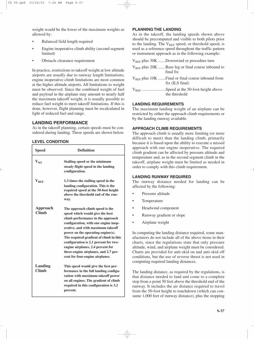
LANDING PERFORMANCEAs in the takeoff planning, certain speeds must be con-sidered during landing. These speeds are shown below.
LEVEL CONDITION
PLANNING THE LANDINGAs in the takeoff, the landing speeds shown aboveshould be precomputed and visible to both pilots priorto the landing. The VREF speed, or threshold speed, isused as a reference speed throughout the traffic patternor instrument approach as in the following example:
VREF plus 30K .......Downwind or procedure turn
VREF plus 20K .......Base leg or final course inbound tofinal fix
VREF plus 10K .......Final or final course inbound from fix (ILS final)
VREF .......................Speed at the 50-foot height above the threshold
LANDING REQUIREMENTSThe maximum landing weight of an airplane can berestricted by either the approach climb requirements orby the landing runway available.
APPROACH CLIMB REQUIREMENTSThe approach climb is usually more limiting (or moredifficult to meet) than the landing climb, primarilybecause it is based upon the ability to execute a missedapproach with one engine inoperative. The requiredclimb gradient can be affected by pressure altitude andtemperature and, as in the second segment climb in thetakeoff, airplane weight must be limited as needed inorder to comply with this climb requirement.
LANDING RUNWAY REQUIREDThe runway distance needed for landing can beaffected by the following:
• Pressure altitude
• Temperature
• Headwind component
• Runway gradient or slope
• Airplane weight
In computing the landing distance required, some man-ufacturers do not include all of the above items in theircharts, since the regulations state that only pressurealtitude, wind, and airplane weight must be considered.Charts are provided for anti-skid on and anti-skid offconditions, but the use of reverse thrust is not used incomputing required landing distances.
The landing distance, as required by the regulations, isthat distance needed to land and come to a completestop from a point 50 feet above the threshold end of therunway. It includes the air distance required to travelfrom the 50-foot height to touchdown (which can con-sume 1,000 feet of runway distance), plus the stopping
Speed Definition
VSO Stalling speed or the minimum steady flight speed in the landing configuration.
VREF 1.3 times the stalling speed in the landing configuration. This is the required speed at the 50-foot height above the threshold end of the run-way.
The approach climb speed is the speed which would give the best climb performance in the approach configuration, with one engine inop-erative, and with maximum takeoff power on the operating engine(s). The required gradient of climb in thisconfiguration is 2.1 percent for two-engine airplanes, 2.4 percent for three-engine airplanes, and 2.7 per-cent for four-engine airplanes.
This speed would give the best per-formance in the full landing configu-ration with maximum takeoff power on all engines. The gradient of climb required in this configuration is 3.2 percent.
ApproachClimb
LandingClimb
Ch 09.qxd 10/24/03 7:24 AM Page 9-37
9-38
distance, with no margin left over. This is all that isrequired for 14 CFR part 91 operators (non-air carrier),and all that is shown on some landing distance requiredcharts.
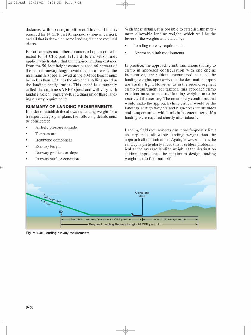
For air carriers and other commercial operators sub-jected to 14 CFR part 121, a different set of rulesapplies which states that the required landing distancefrom the 50-foot height cannot exceed 60 percent ofthe actual runway length available. In all cases, theminimum airspeed allowed at the 50-foot height mustbe no less than 1.3 times the airplane’s stalling speed inthe landing configuration. This speed is commonlycalled the airplane’s VREF speed and will vary withlanding weight. Figure 9-40 is a diagram of these land-ing runway requirements.
SUMMARY OF LANDING REQUIREMENTSIn order to establish the allowable landing weight for atransport category airplane, the following details mustbe considered:
• Airfield pressure altitude
• Temperature
• Headwind component
• Runway length
• Runway gradient or slope
• Runway surface condition
With these details, it is possible to establish the maxi-mum allowable landing weight, which will be thelower of the weights as dictated by:
• Landing runway requirements
• Approach climb requirements
In practice, the approach climb limitations (ability toclimb in approach configuration with one engineinoperative) are seldom encountered because thelanding weights upon arrival at the destination airportare usually light. However, as in the second segmentclimb requirement for takeoff, this approach climbgradient must be met and landing weights must berestricted if necessary. The most likely conditions thatwould make the approach climb critical would be thelandings at high weights and high-pressure altitudesand temperatures, which might be encountered if alanding were required shortly after takeoff.
Landing field requirements can more frequently limitan airplane’s allowable landing weight than theapproach climb limitations. Again, however, unless therunway is particularly short, this is seldom problemat-ical as the average landing weight at the destinationseldom approaches the maximum design landingweight due to fuel burn off.
CompleteStop
Required Landing Distance 14 CFR part 91 40% of Runway Length
Required Landing Runway Length 14 CFR part 121
50'
1.3 VS0
VS0 Approach
Figure 9-40. Landing runway requirements.
Ch 09.qxd 10/24/03 7:24 AM Page 9-38
9-39
EXAMPLES OF PERFORMANCE CHARTS
Figures 9-41 through 9-62 are examples of charts used for transport category airplanes.
Ch 09.qxd 10/24/03 7:24 AM Page 9-39
9-40
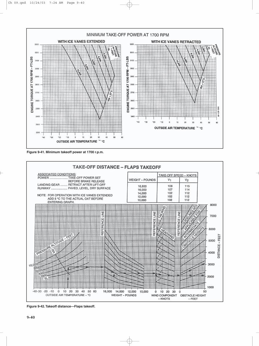
Figure 9-41. Minimum takeoff power at 1700 r.p.m.
Figure 9-42.Takeoff distance—Flaps takeoff.
Ch 09.qxd 10/24/03 7:24 AM Page 9-40
9-41
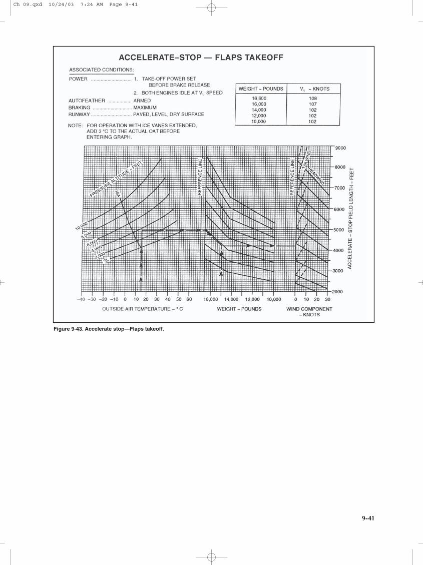
Figure 9-43. Accelerate stop—Flaps takeoff.
Ch 09.qxd 10/24/03 7:24 AM Page 9-41
9-42
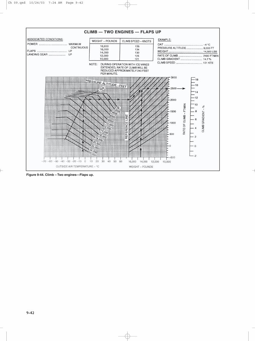
Figure 9-44. Climb – Two engines—Flaps up.
Ch 09.qxd 10/24/03 7:24 AM Page 9-42
9-43
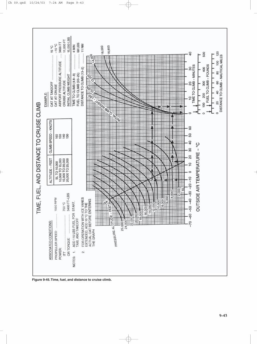
Figure 9-45.Time, fuel, and distance to cruise climb.
Ch 09.qxd 10/24/03 7:24 AM Page 9-43
9-44
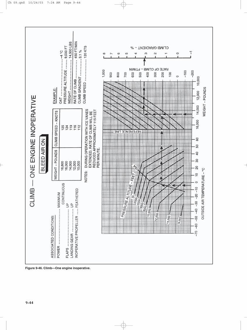
Figure 9-46. Climb—One engine inoperative.
Ch 09.qxd 10/24/03 7:24 AM Page 9-44
9-45
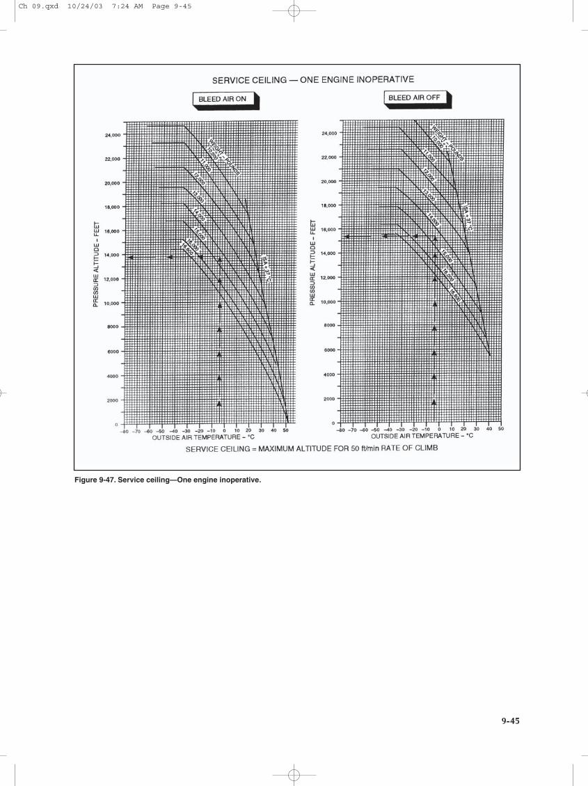
Figure 9-47. Service ceiling—One engine inoperative.
Ch 09.qxd 10/24/03 7:24 AM Page 9-45