Embed Size (px)
Citation preview

IEEE TRANSACTIONS ON INSTRUMENTATION AND MEASUREMENT, VOL. 58, NO. 8, AUGUST 2009 2385
Performance Evaluation of 3D-LOCUSAdvanced Acoustic LPS
José Carlos Prieto, Antonio Ramón Jiménez, Jorge Guevara, Joao L. Ealo,Fernando Seco, Javier O. Roa, and Francisco Ramos
Abstract—Local Positioning Systems (LPSs) based on acoustictransducers (mainly ultrasonic) offer accurate localization in in-door environments. However, their performance is commonlylimited by the transducers’ frequency bandwidth and emissionpattern. 3D-LOCUS is a new advanced acoustic LPS that claimssubcentimeter accuracy even in turbulent environments. This isachieved through the use of broadband omnidirectional trans-ducers, suitable design of emitted signals, proper calibration, andbidirectional emissions. This paper evaluates the 3D-LOCUS LPSby providing results in terms of some positioning metrics suchas accuracy, resolution, and coverage, which show how it outper-forms other state-of-the-art LPS prototypes. 3D-LOCUS operat-ing in bidirectional mode minimizes environmental effects, suchas temperature and airflows, attaining localization errors below9 mm with a 90% confidence level, an RMS error below 7.4 mm,and 5 mm resolution in a localization volume of 2 × 2 × 0.4 m3.
Index Terms—Accurate localization, broadband transducers,Local Positioning Systems (LPSs), system evaluation, ubiquitouscomputing.
I. INTRODUCTION
THE demand of new location-aware solutions for newnecessities has triggered the research and development of
new location platforms for accurate or physical localization(some interesting surveys can be found in [2] and [3]). Thedesign of these platforms strongly depends on the applicationin mind, for example, to operate outdoor or indoors. Themost prominent technology for outdoor environments is theNAVSTAR Global Positioning System (GPS), which is oflimited use indoors [4]. Systems designed to operate indoorsare usually referred to as Local Positioning Systems (LPSs)
Manuscript received December 30, 2007; revised July 23, 2008. First pub-lished May 26, 2009; current version published July 17, 2009. The work ofJ. C. Prieto was supported by an I3P grant from the Consejo Superior deInvestigaciones Científicas (CSIC). This work was supported by the SpanishMinistry of Science and Technology under PARMEI Project DIP2003-08715-C02-02. The Associate Editor coordinating the review process wasDr. Jesús Ureña.
J. C. Prieto, A. R. Jiménez, J. Guevara, F. Seco, and J. O. Roa are withthe LOPSI Group, Instituto de Automática Industrial, Consejo Superior deInvestigaciones Científicas (CSIC), 28500 Madrid, Spain (e-mail: [email protected]).
J. L. Ealo is with the LOPSI Group, Instituto de Automática Industrial, CSIC,28500 Madrid, Spain, and also with the School of Mechanical Engineering,Universidad del Valle, Cali 25360, Colombia.
F. Ramos was with the LOPSI Group, Instituto de Automática Indus-trial, CSIC, 28500 Madrid, Spain. He is now with NOVATRONIC, Quito,Ecuador.
Color versions of one or more of the figures in this paper are available onlineat http://ieeexplore.ieee.org.
Digital Object Identifier 10.1109/TIM.2009.2016378
since they are designed for covering an enclosed area such asa building, a room, etc.
Recent research on positioning systems aims to improvethe positioning accuracy. This can mainly be achieved bya precise estimation of the range between a beacon and areceiver; in particular, for GPS, by differential carrier-basedranging and trilateration techniques. The GPS technology isnow able to obtain positioning errors as low as 20 mm withReal-Time Kinematics Differential GPS (DGPS-RTK) [5] inoutdoor environments free of obstacles. LPSs based on Timeof Flight (ToF) measurements such as Ultra-Wideband (UWB)achieve accuracies of tens of centimeters [6], [7]. LPSs basedon Received Signal Strength Indicator (RSSI) such as severalimplementations using Wifi [8], RFID [9], or mobile networkshave several meters of error. Artificial vision developmentsachieve accuracies of several centimeters [10]. Systems basedon acoustic signals are able to attain accuracies of a fewcentimeters, with the most representatives being Active Bat[11], Cricket [12], SmartLocus [13], and Dolphin units [14].
Recently, in [1], a new advanced acoustic location systemwas presented by the authors of this paper. This LPS, which iscalled 3D-LOCUS, outperforms current acoustic LPSs by beingable to precisely determine a mobile target position with sub-centimeter accuracy. Additionally, 3D-LOCUS has the abilityto compensate temperature gradients and airflows. Its accuracyis independent of the node’s orientation, since transducers havea virtual point-like center of emission and reception. Its flexi-bility to work as a centralized, privacy-oriented, or bidirectionalsystem, together with the parameterization of different accessmodes and signal designs, makes it easy to compare it to similarsystems reported in the literature. The 3D-LOCUS distributedcomputing architecture is able to update the target positionup to ten times per second in Code-Division Multiple-Access(CDMA) centralized mode.
In this paper, we present a complete evaluation of theperformance of the 3D-LOCUS system. Section II presentsa model for the 3D-LOCUS acoustic emission and receptionprocess. Taking into account the expected ranging precisionand its dependency with the properties of the signal, we design,according to this model, a good signal for emission and a propersampling for reception. Section III evaluates the goodness ofthe 3D-LOCUS calibration method. It compares the estimatedposition of the transducers at every fixed node in severalseparate calibrations. Finally, in Section IV, the positioningperformance obtained with this system is evaluated in termsof RMS errors and confidence levels while also taking intoaccount several aspects, such as resolution and coverage, which
0018-9456/$25.00 © 2009 IEEE

2386 IEEE TRANSACTIONS ON INSTRUMENTATION AND MEASUREMENT, VOL. 58, NO. 8, AUGUST 2009
Fig. 1. Transfer functions that model the available bandwidth in the emission/reception process of the 3D-LOCUS system showing its dependence on thetransducers’ orientation. (a) Transfer function gain. (b) Transfer function phase.
are not usually evaluated in other LPS systems. A discussionand some conclusions are given in Section V.
II. SIGNAL PARAMETER SELECTION
Sonic signals generated by 3D-LOCUS nodes are basedon BPSK-modulated spreading Golay codes [15], specifically,preferred groups of unpaired codes [16]. These signals arecorrelated at the receiver for ToF estimation, which makes useof an efficient Golay correlator (EGC) [17]. The use of suchsignals improves the ranging accuracy and robustness againstenvironmental noise and enables code-multiplexing schemes.
The use of full Golay pairs was not considered since itwould make difficult the easy expansion of the system. In itscurrent implementation, the system could receive and processfull Golay signals since all the processing is implemented insoftware; but it only has enough hardware for emitting BPSKsignals.
The main parameters selected for the emitted signal arethe carrier frequency (fc), the length of the sequence, andthe number of carrier cycles per code chip. For reception, weneed to select the sampling frequency (fs). To obtain theseparameters, we will consider a fixed signal-to-noise ratio andtwo models of the acoustic transmission channel.
An experimental identification of the transfer function ofthe ultrasonic channel was accomplished. This model includes,apart from the channel effect, the electronics and transducerinfluence on the signal. The transfer function was obtained byemitting a chirp signal from 0 Hz to 500 kHz, acquiring thereceived signal at a sampling rate of 1 MHz, and adjustingan IIR filter of order 10 by minimizing the output error, i.e.,the difference between filter and system outputs. Fig. 1 showsthe transfer function obtained at several orientations betweenemitter and receiver. Note that the usable bandwidth diminishesas obliqueness increases [Fig. 1(a)], but the effective bandwidthis about 20 kHz for most orientations considering a 6 dB band.The phase change [Fig. 1(b)] is quite smooth for the frequen-
cies of interest (5–25 kHz) if the orientation between bothtransducers is equal or lower than 60◦. At higher orientationangles, the phase response is worsened outside the 5–20 kHzwindow.
This transfer function was used for evaluating the influenceof carrier, code, and sampling frequencies, as well as codelength, on the precision of the measuring process. Fig. 2 showsthe influence of the considered parameters on the variance ofdistance estimation. The study is performed by simulation usingtwo transfer function models: 1) ideal (red circles), with infinitebandwidth, so that the received signal is the same as the emittedsignal; and 2) the transfer function previously mentioned above(blue), identified for the 3D-LOCUS system, without rotation(asterisks), 30◦ rotation (squares), 45◦ rotation (diamonds), and60◦ rotation (triangles). Signals are corrupted with additivewhite Gaussian noise to achieve an SNR of 12 dB.
This figure shows the main influence of the rotation angleon the range measurements: the increment of the variance.This influence also depends on the parameters of the signal,i.e., being more important for lower sampling frequencies, forinstance.
Fig. 2(a) shows the influence of the modulating carrier fre-quency (fc). The variance will decrease with higher frequenciesin the ideal response, since the bandwidth of the resulting signalincreases [18]. The filtered response will be more affected whenthe carrier approaches the band edges, since part of the signalwill be filtered. The minimum of the variance depends on themodel used. Since the higher frequencies are more affected bytransducer rotation (as shown in Fig. 1), 15 kHz is chosen as atrade of frequency, which is valid for most orientations betweentransducers, for the modulating carrier.
Fig. 2(b) shows the influence of the number of carrier cy-cles used for modulating every code chip (carrier and codefrequencies ratio). The number of cycles per chip defines thechip duration and, therefore, the signal bandwidth. We see thatthe ideal response is not affected when the signal bandwidth isincreased (fewer cycles per chip). A good behavior for every

PRIETO et al.: PERFORMANCE EVALUATION OF 3D-LOCUS ADVANCED ACOUSTIC LPS 2387
Fig. 2. Simulated ranging performance (standard deviation of range estimations) influenced by the selection of modulation, codification, and acquisitionparameters. Default parameters: fc = 15 kHz, fs = 150 kHz, cycles/chip = 1, SNR = 12 dB, and L = 32 chips. (a) Carrier frequency. (b) Cycles per chip.(c) Sequence length. (d) Sampling frequency.
transducer’s orientation is found using one or more cycles perchip. Therefore, to shorten the resulting signal as much aspossible (for avoiding the effect of air turbulence), we use onecycle per chip.
When analyzing the ToF variance with respect to the lengthof the sequence, we find, as expected, that the longer is thesequence, the smaller is the variance [Fig. 2(c)]. However,taking into account possible turbulences, it is important tokeep the duration of the signal short. The proper correlation ofspread-spectrum-coded signals is very sensitive to turbulencesin the air; fortunately, due to the dynamics of air, there is atime threshold for the duration of the signal (10 ms) that, ifnot surpassed, makes signal correlation quite robust against tur-bulences [19]. A good compromise between a short signal anda low variance is obtained using 32 chip long codes (L = 32).
Finally, the variance will be lower with higher samplingfrequencies (fs) used in the receiver [Fig. 2(d)]; however,this implies more computation time. It can be noticed that,at frequencies below 100 kHz, the standard deviation of theToF significantly grows for orientations higher than 60◦. Forguarantying good accuracy in most circumstances, 150 kHz is
chosen as the sampling frequency. At this sampling rate, tensamples are used to digitize each carrier cycle.
Subsequent evaluation tests of 3D-LOCUS will use as theemitted signal a Golay code with 32 chips, which is modulatedwith 1 cycle per chip and a 15 kHz carrier. Acquisition willbe performed at the receiver with a sampling frequency of150 kHz. This signal design took into account the variablebandwidth, which depends on the transducer rotation, theexpected influence of air turbulences, and the computationalcomplexity of the receiver.
III. NODE’S POSITION CALIBRATION ASSESSMENT
We deployed seven fixed wired nodes oriented downward ina robotic cell (2800 mm × 2800 mm × 2800 mm) (Fig. 3).One additional wired node was located inside the cell pointingupward. A Stäubli Unimation industrial robotic arm is usedas reference for positioning a mobile wireless node fixed toits wrist as a tool, which is always oriented upward. Thesenodes are numbered from 1 to 9, where the number 3 is themobile node, the number 6 is the fixed upward node, and the
2388 IEEE TRANSACTIONS ON INSTRUMENTATION AND MEASUREMENT, VOL. 58, NO. 8, AUGUST 2009
Fig. 3. Physical description of the actual implementation of the 3D-LOCUSsystem labeling its main components: fixed nodes in the structure, mobile nodein the robot wrist, central node for measurement synchronization, and industrialfan for air perturbations.
rest correspond to the fixed downward nodes, which are alsocalled beacons.
The calibration of the node’s position was performed bypositioning the wireless node in four points with the robot armand measuring the ToFs to the emitter and the receiver of everynode fixed to the cell structure. Three of these points werearranged to form an almost equilateral triangle, and the fourth isin its center at a different height. From these measurements, thesound velocity and the 3-D coordinates of every node’s emitterand receiver were calculated, which was made considering thesound velocity as unknown in the trilateration equations [20],in the upward (1) and downward (2) propagation directions:
VsToFij =√
(xrj−xei
)2+(yrj−yei
)2+(zrj−zei
)2 (1)
VsToFji =√
(xej−xri
)2+(yej−yri
)2+(zej−zri
)2 (2)
whereVs estimated sound velocity;ToFij/ji ToF measured from the mobile node at
point i to the beacon j or in the otherdirection;
(xe/rj, ye/rj
, ze/rj) estimated position or the transducers
(e: emitter, r: receiver) of the fixednode j;
(xe/ri, ye/ri
, ze/ri) known mobile transducers’ (e: emitter,
r: receiver) position at point i.
This algorithm minimizes the effect of environmental tem-perature drifts and gradients on positioning, since it determinesan averaged value for the sound velocity without having to usea thermometer. If Vs is estimated with a temperature measure-ment, then it will depend on the spatial position where thetemperature is measured, which could not fully correspond tothe temperature of the path followed by the acoustic signal.
The consistency of calibration results was evaluated by re-peating 11 independent node position calibrations. The vari-ation of every (xe/rj
, ye/rj, ze/rj
) coordinate with respect totheir mean is shown in Fig. 4 for emitters (first column) andreceivers (second column). It can be noticed that the variabilityof the emitters is higher than that of the receivers. We believethat this effect is due to the higher omnidirectionality of thereceivers that can capture some multipath produced in therobotic arm. The repetitiveness of the transducers’ position isapproximately bounded by ±2 mm for emitters and ±1 mm forreceivers on every coordinate.
Since there is no real knowledge of the exact position ofemitters and receivers, we considered an indirect procedureto estimate the calibration performance. The actual distancebetween both transducers’ center on every node (64.11 mm) isused as an indication of calibration accuracy. Fig. 5(a) showsthe distances obtained from the calibration data. The meanmeasured distance between both transducers, considering allthe nodes, is about 64 mm, with variations of ±4 mm. Fig. 5(b)shows the variability of the measured distance relative to themean distance of every node, with variations of ±2 mm. Theseresults suggest that the calibration of the fixed node transducers’position is accurate at the millimeter level, and the system isready for positioning evaluation.
IV. POSITIONING EVALUATION
Most ultrasonic LPS evaluations only rely on the overallaccuracy achieved by the system under some confidence level.In this section, a more detailed evaluation of the 3D-LOCUSpositioning error will be presented, which takes into account thepercentage of valid measurements, precision, trueness, RMSvalues, and overall error accuracy. Afterward, an analysis of thesystem resolution will be presented. Finally, an evaluation ofthe coverage of the system will be shown.
A. Positioning Error
For evaluating the error present in 3-D position estimation,three different configurations were considered.
1) Centralized: the nodes oriented upward act as emitters,and the nodes fixed downward act as receivers.
2) Privacy oriented: the nodes fixed to the cell structure actas emitters (i.e., sound waves propagate in the oppositedirection than in the centralized mode).
3) Bidirectional: both ways sequentially.
In the last case, both emitter and receiver positions of themobile node are determined. The average of both positionestimations is considered as the resulting position of the node.

PRIETO et al.: PERFORMANCE EVALUATION OF 3D-LOCUS ADVANCED ACOUSTIC LPS 2389
Fig. 4. Evaluation of the transducers’ position consistency of the seven fixed nodes for 11 independent calibrations, showing the fluctuation of the positionestimation of their emitters and receivers for every coordinate axes. (a) xej fluctuations. (b) xrj fluctuations. (c) yej fluctuations. (d) yrj fluctuations.
(e) zej fluctuations. (f) zrj fluctuations.

2390 IEEE TRANSACTIONS ON INSTRUMENTATION AND MEASUREMENT, VOL. 58, NO. 8, AUGUST 2009
Fig. 5. Evaluation of the transducers’ distance consistency of the seven fixed downward nodes for each of the 11 calibrations, showing the variation in distanceobtained for separate nodes and its variation with different calibrations. (a) Distance between nodes’ transducers. (b) Distance variation around their mean.
The following four test conditions were evaluated for everyconfiguration:
1) time multiplexing (Time-Division Multiple Access,TDMA) (calm air);
2) code multiplexing (CDMA1) (calm air);3) TDMA with airflows (fan stream at 2 m/s);4) CDMA1 with airflows (fan stream at 2 m/s).
The first condition is the most ideal case since neither winddisturbances nor signal interference is present. The CDMAmode presents signal degradation due to the interference amongsignals coming from different nodes. The potential deteriora-tion of signal correlation that can be caused by air turbulence isminimized by the short signal length, as presented in Section II.However, airflows produce distance measurement degradationsince the ToF varies when the propagation medium (air) moves(airflow).
CDMA measurements are degraded by two highly relatedfactors: Multiple-Access Interference (MAI) and the near–fareffect. The latter is due to power differences among the receivedsignals from each emitting node. It was reduced enough toenable correct measurements, i.e., readjusting the emissionpower in every point in CDMA mode. The two upward nodeswere tested by emitting the same power. The MAI errors aredue to the cross-correlation properties of the codes (since theyare not completely orthogonal) and worsened because of thenear–far effect. In this paper, MAI was reduced by selecting agroup of codes with good cross-correlation properties.
The update rate depends on the access mode (TDMA orCDMA) and the configuration. In TDMA mode, the signalsare sequentially emitted from every node, requiring more timethan in CDMA mode, where all the signals are simultaneouslyemitted. If 3D-LOCUS is configured to only transfer ToFs fromthe sensing nodes to the central node (fastest operation mode),
1Multiple-access configurations were tested with just four downward nodes.
TABLE ITWENTY-TWO TEST POINTS CONSIDERED FOR SYSTEM EVALUATION
then the update rate is 10 Hz in CDMA centralized mode (thehigher) and 2 Hz in TDMA bidirectional mode (the lower). Ifthe number of fixed nodes is duplicated, then the update ratewould be 1 Hz in TDMA.
For every configuration and test condition, 22 test positionswere defined, and more than 100 measurements were made oneach position. One position was in the center of the cell, andthe remaining 21 were in seven different “xy” points around therobot at three different heights (differing by 200 mm). Table Idefines the exact position of these 22 test points.
Position and sound velocity were estimated from (1) and (2)through a Levenberg–Marquardt algorithm, which minimizesthe sum of the squared residuals, defined as the differencebetween both terms of the equations. A point located 1.5 m
PRIETO et al.: PERFORMANCE EVALUATION OF 3D-LOCUS ADVANCED ACOUSTIC LPS 2391
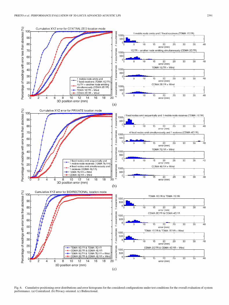
Fig. 6. Cumulative positioning error distributions and error histograms for the considered configurations under test conditions for the overall evaluation of systemperformance. (a) Centralized. (b) Privacy oriented. (c) Bidirectional.
2392 IEEE TRANSACTIONS ON INSTRUMENTATION AND MEASUREMENT, VOL. 58, NO. 8, AUGUST 2009
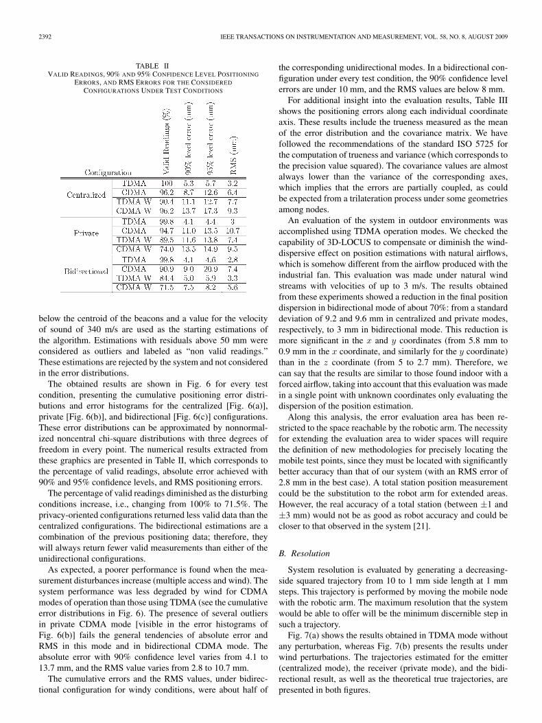
TABLE IIVALID READINGS, 90% AND 95% CONFIDENCE LEVEL POSITIONING
ERRORS, AND RMS ERRORS FOR THE CONSIDERED
CONFIGURATIONS UNDER TEST CONDITIONS
below the centroid of the beacons and a value for the velocityof sound of 340 m/s are used as the starting estimations ofthe algorithm. Estimations with residuals above 50 mm wereconsidered as outliers and labeled as “non valid readings.”These estimations are rejected by the system and not consideredin the error distributions.
The obtained results are shown in Fig. 6 for every testcondition, presenting the cumulative positioning error distri-butions and error histograms for the centralized [Fig. 6(a)],private [Fig. 6(b)], and bidirectional [Fig. 6(c)] configurations.These error distributions can be approximated by nonnormal-ized noncentral chi-square distributions with three degrees offreedom in every point. The numerical results extracted fromthese graphics are presented in Table II, which corresponds tothe percentage of valid readings, absolute error achieved with90% and 95% confidence levels, and RMS positioning errors.
The percentage of valid readings diminished as the disturbingconditions increase, i.e., changing from 100% to 71.5%. Theprivacy-oriented configurations returned less valid data than thecentralized configurations. The bidirectional estimations are acombination of the previous positioning data; therefore, theywill always return fewer valid measurements than either of theunidirectional configurations.
As expected, a poorer performance is found when the mea-surement disturbances increase (multiple access and wind). Thesystem performance was less degraded by wind for CDMAmodes of operation than those using TDMA (see the cumulativeerror distributions in Fig. 6). The presence of several outliersin private CDMA mode [visible in the error histograms ofFig. 6(b)] fails the general tendencies of absolute error andRMS in this mode and in bidirectional CDMA mode. Theabsolute error with 90% confidence level varies from 4.1 to13.7 mm, and the RMS value varies from 2.8 to 10.7 mm.
The cumulative errors and the RMS values, under bidirec-tional configuration for windy conditions, were about half of
the corresponding unidirectional modes. In a bidirectional con-figuration under every test condition, the 90% confidence levelerrors are under 10 mm, and the RMS values are below 8 mm.
For additional insight into the evaluation results, Table IIIshows the positioning errors along each individual coordinateaxis. These results include the trueness measured as the meanof the error distribution and the covariance matrix. We havefollowed the recommendations of the standard ISO 5725 forthe computation of trueness and variance (which corresponds tothe precision value squared). The covariance values are almostalways lower than the variance of the corresponding axes,which implies that the errors are partially coupled, as couldbe expected from a trilateration process under some geometriesamong nodes.
An evaluation of the system in outdoor environments wasaccomplished using TDMA operation modes. We checked thecapability of 3D-LOCUS to compensate or diminish the wind-dispersive effect on position estimations with natural airflows,which is somehow different from the airflow produced with theindustrial fan. This evaluation was made under natural windstreams with velocities of up to 3 m/s. The results obtainedfrom these experiments showed a reduction in the final positiondispersion in bidirectional mode of about 70%: from a standarddeviation of 9.2 and 9.6 mm in centralized and private modes,respectively, to 3 mm in bidirectional mode. This reduction ismore significant in the x and y coordinates (from 5.8 mm to0.9 mm in the x coordinate, and similarly for the y coordinate)than in the z coordinate (from 5 to 2.7 mm). Therefore, wecan say that the results are similar to those found indoor with aforced airflow, taking into account that this evaluation was madein a single point with unknown coordinates only evaluating thedispersion of the position estimation.
Along this analysis, the error evaluation area has been re-stricted to the space reachable by the robotic arm. The necessityfor extending the evaluation area to wider spaces will requirethe definition of new methodologies for precisely locating themobile test points, since they must be located with significantlybetter accuracy than that of our system (with an RMS error of2.8 mm in the best case). A total station position measurementcould be the substitution to the robot arm for extended areas.However, the real accuracy of a total station (between ±1 and±3 mm) would not be as good as robot accuracy and could becloser to that observed in the system [21].
B. Resolution
System resolution is evaluated by generating a decreasing-side squared trajectory from 10 to 1 mm side length at 1 mmsteps. This trajectory is performed by moving the mobile nodewith the robotic arm. The maximum resolution that the systemwould be able to offer will be the minimum discernible step insuch a trajectory.
Fig. 7(a) shows the results obtained in TDMA mode withoutany perturbation, whereas Fig. 7(b) presents the results underwind perturbations. The trajectories estimated for the emitter(centralized mode), the receiver (private mode), and the bidi-rectional result, as well as the theoretical true trajectories, arepresented in both figures.

PRIETO et al.: PERFORMANCE EVALUATION OF 3D-LOCUS ADVANCED ACOUSTIC LPS 2393
TABLE IIICOORDINATE AXES ERRORS: 90% AND 95% CONFIDENCE LEVEL ERRORS, TRUENESS, RMS ERRORS,
AND COVARIANCES FOR THE CONSIDERED CONFIGURATIONS UNDER TEST CONDITIONS
Fig. 7. Stair-stepped squared trajectory described by the mobile node in TDMA mode for resolution evaluation (minimum discernible step). Trajectories followedby emitter, receiver, and central point correspond to centralized (red), privacy oriented (pink), and bidirectional (blue) configurations, respectively. (a) Withoutwind. (b) Under wind disturbances.
The results shown in Fig. 7(a) indicate that, without anyperturbation, it is possible to distinguish 2 mm steps on everytrajectory. Under airflow conditions, the attained resolution isabout 10 mm for private and centralized mode and about 5 mmin bidirectional mode. Therefore, the bidirectional operationmode in 3D-LOCUS is good not only for achieving subcentime-ter positioning error but also for obtaining a good resolution.
The system resolution was also evaluated for CDMA opera-tion, finding that the 3D-LOCUS system was not able to followthe trajectory in this mode due to many nonvalid estimations.This is because of the fact that neither a MAI cancellationscheme nor an automatic adaptation of the emission power hasbeen implemented up to now in the 3D-LOCUS system.
C. Coverage
The capacity of the system to make measurements outside therobotic cell was evaluated by manually moving the mobile nodefollowing a zig-zag trajectory. This system is able to localizefar from the cell due to the omnidirectional characteristics oftheir transducers [1]. This evaluation was performed in justone quadrant, considering that the obtained results can beextrapolated to the remaining three.
Fig. 8 shows the result obtained. It can be appreciated anapproximately circular coverage area of 4 m radius (circulardotted line). The system accuracy is lower in this area dueto the poorer geometry (high Geometric Dilution of Precision(GDOP) [22]), the higher dispersion in ToF measurements due

2394 IEEE TRANSACTIONS ON INSTRUMENTATION AND MEASUREMENT, VOL. 58, NO. 8, AUGUST 2009
Fig. 8. Coverage obtained when manually moving the mobile node outsidethe robotic cell. The seven fixed downward nodes are represented by a red circleand a cross (emitter and receiver of each node, respectively).
to an increase of the orientation between transducers, and thelonger propagation times.
This result does not imply that the best configuration for cov-ering this area is the one presented, it just offers an evaluationof the capability of the nodes for covering areas not enclosedby them, and this feature is enabled by the good directionalitypattern of the selected transducers and the rotational invarianceof the range measurements [1]. The practical consequence isthat the node density necessary for obtaining complete coveragein a final deployment can be very low. The evaluation of themaximum area that could be covered separating these sevennodes has to be studied.
V. CONCLUSION
The evaluation of the 3D-LOCUS acoustic LPS has beenpresented. The main parameters involved on signal emissionand reception were selected for accurate ranging, taking into ac-count the bandwidth and directionality of the transducers. Thecalibration process for fixed nodes’ position determination wasevaluated, finding it repetitive and accurate. The 3D-LOCUSpositioning performance was evaluated by considering severalimportant aspects that are not usually reported with enough de-tail in other LPS evaluations. Apart from the absolute error andthe valid reading evaluation, a measure of trueness, precision,RMS error, resolution, and maximum attainable coverage wasoffered.
The 3D-LOCUS system, in bidirectional mode, has subcen-timeter accuracy (RMS errors below 8 mm), is able to reach5 mm resolution, and possesses a wide coverage. These resultsare also valid even under moderate airflows. Therefore, theimplemented system outperforms (in terms of accuracy, res-olution and coverage) those LPSs found on the bibliography.3D-LOCUS could be considered as the first subcentimeter-accuracy acoustic LPS usable in both indoor and outdoor
environments, and it is a flexible platform to test future researchon precise positioning.
ACKNOWLEDGMENT
The authors would like to thank the suggestions of theanonymous reviewers.
REFERENCES
[1] J. C. Prieto, A. R. Jiménez, J. I. Guevara, J. L. Ealo, F. A. Seco,J. O. Roa, and F. X. Ramos, “Subcentimeter-accuracy localization throughbroadband acoustic transducers,” in Proc. IEEE Int. Symp. Intell. SignalProcess., Alcalá de Henares, Spain, Oct. 3–5, 2007, pp. 929–934.
[2] J. Hightower and G. Borriello, “Location systems for ubiquitouscomputing,” Computer, vol. 34, no. 8, pp. 57–66, Aug. 2001.
[3] A. R. Jiménez, F. Seco, R. Ceres, and L. Calderón, Absolute Localiza-tion Using Active Beacons: A Survey and IAI-CSIC Contributions, 2004.[Online]. Available: http://www.iai.csic.es/lopsi/static/phdteaching.htm
[4] P. Mattos, “Acquiring sensitivity to bring new signals indoors,” GPSWorld, vol. 15, no. 5, pp. 28–33, May 2004.
[5] H. Baertlein, B. Carlson, R. Eckels, S. Lyle, and S. Wilson, “A high-performance, high-accuracy RTK GPS machine guidance system,” GPSSolut., vol. 3, no. 3, pp. 4–11, Jan. 2000.
[6] R. J. Fontana, “Recent applications of ultra wide band radar and com-munications systems,” Multispectral Solutions, Germantown, MD, 2000,Tech. Rep.
[7] C. Falsi, D. Dardari, L. Mucchi, and M. Z. Win, “Time of arrival esti-mation for UWB localizers in realistic environments,” EURASIP J. Appl.Signal Process., vol. 2006, no. 1, p. 152, Jan. 2006.
[8] P. Bahl and V. N. Padmanabhan, “Radar: An in-building user location andtracking system,” in Proc. IEEE INFOCOM, 2000, vol. 2, pp. 775–784.Tel Aviv, Israel.
[9] L. M. Ni, Y. Liu, Y. C. Lau, and A. P. Patil, “Landmarc: Indoor locationsensing using active RFID,” Wirel. Netw.—Special Issue Pervasive Com-put. Commun., vol. 10, no. 6, pp. 701–710, Nov. 2004.
[10] J. Krumm, S. Harris, B. Meyers, B. Brumitt, M. Hale, and S. Shafer,“Multi-camera multiperson tracking for easyliving,” in Proc. 3rd IEEEInt. Workshop VS, 2000, pp. 3–10.
[11] A. Harter, A. Hopper, P. Steggles, A. Ward, and P. Webster, “The anatomyof a context-aware application,” in Proc. 5th Annu. ACM/IEEE Int. Conf.Mobicom, 1999, pp. 1–59.
[12] H. Balakrishnan and N. Priyantha, “The Cricket indoor location sys-tem: Experience and status,” in Proc. WorkShop Location-Aware Comput.Ubicomp, 2003, vol. 1, pp. 7–9.
[13] C. Brignone, T. Connors, G. Lyon, and S. Pradhan, “SmartLOCUS: Anautonomous, self-assembling sensor network for indoor asset and systemsmanagement,” Mobile Media Syst. Lab., HP Laboratories, Palo Alto, CA,Tech. Rep. 41, 2003.
[14] M. Hazas and A. Hopper, “Broadband ultrasonic location systems forimproved indoor positioning,” IEEE Trans. Mobile Comput., vol. 5, no. 5,pp. 536–547, May 2006.
[15] M. J. E. Golay, “Complementary series,” IRE Trans. Inf. Theory, vol. IT-7,no. 2, pp. 82–87, Apr. 1961.
[16] C. De Marziani, J. Ureña, M. Mazo, Á. Hernández, and J. M. Villadangos,“Algoritmo de posicionamiento en sistemas de localización de redes desensores acústicos inteligentes,” in Proc. Int. Conf. TELEC, Santiago deCuba, Cuba, Jul. 14–16, 2004.
[17] B. M. Popovic, “Efficient Golay correlator,” Electron. Lett., vol. 35,no. 17, pp. 1427–1428, Aug. 1999.
[18] E. Weinstein and A. J. Weiss, “Fundamental limitations in passive time-delay estimation—Part II: Wide-band systems,” IEEE Trans. Acoust.,Speech, Signal Process., vol. ASSP-32, no. 5, pp. 1064–1078, Oct. 1984.
[19] F. J. Alvarez, J. Ureña, M. Mazo, A. Hernández, J. J. García, andC. Marziani, “High reliability outdoor sonar prototype based on efficientsignal coding,” IEEE Trans. Ultrason., Ferroelectr., Freq. Control, vol. 53,no. 10, pp. 1862–1872, Oct. 2006.
[20] F. Morgado, A. R. Jiménez, and F. Seco, “Ultrasound-based 3d-coordinatemeasuring system for localization of findings in paleo-archaeologicalexcavations,” in Proc. WAC/ISIAC, Seville, Spain, Jun. 28–Jul. 1, 2004,vol. 16, pp. 216–222.
[21] Trimble, Trimble 3600 Total Station, 2007. [Online]. Available:http://trl.trimble.com//docushare/dsweb//Get/Document-10325/12414C_3600wTCU_DS_0507_lr.pdf
[22] R. Yarlagadda, I. Ali, N. Al-Dhahir, and J. Hershey, “GPS GDOP metric,”Proc. Inst. Elect. Eng.—Radar Sonar Navig., vol. 147, no. 5, pp. 259–264,Oct. 2000.

PRIETO et al.: PERFORMANCE EVALUATION OF 3D-LOCUS ADVANCED ACOUSTIC LPS 2395
José Carlos Prieto was born in León, Spain, in1978. He received the Technical degree in indus-trial electronics and the B.S. degree in electronicsengineering from the Universidad de Extremadura,Badajoz, Spain, in 1999 and 2003, respectively, andthe Master’s degree in robotics from the UniversidadPolitécnica de Madrid, Madrid, Spain, in 2007. Heis currently working toward the Doctoral degree inrobotics with the Universidad de Alcalá, Madrid.
Since 2004, he has been a Researcher with the In-stituto de Automática Industrial, Consejo Superior de
Investigaciones Científicas (CSIC), Madrid. His research interests are focusedin localization systems, mainly those based in ultrasonic signals, with specialemphasis in signal design and processing, positioning algorithms, robustness,standardization, optimal configurations, calibration methods, and developmentof new transducers.
Antonio Ramón Jiménez received the degree inphysics and computer science and the Ph.D. de-gree in physics from the Universidad Complutensede Madrid, Madrid, Spain, in 1991 and 1998,respectively.
From 1991 to 1993, he worked in industriallaser applications with the Technological Center ofMadrid (CETEMA), Madrid. Since 1994, he hasbeen a Researcher with the Instituto de AutomáticaIndustrial, Consejo Superior de InvestigacionesCientíficas (CSIC), Madrid. His current research in-
terests include sensor systems (ultrasound and RFID) and algorithmic solutionsfor localization and tracking of persons or objects in sectors such as robotics,vehicle navigation, and ambient assistive living.
Jorge Guevara was born in Lima, Peru, in 1978. Hereceived the B.S. degree in electronics engineeringfrom the Universidad Católica Nuestra Señora dela Asunción, Asunción, Paraguay, in 2004. He iscurrently working toward the Ph.D. degree in electricengineering with the Instituto de Automática Indus-trial, Consejo Superior de Investigaciones Científicas(CSIC), Madrid, Spain.
His research interests are in the area of localizationsystems, in particular, automatic calibration methodsfor ultrasonic positioning systems.
Joao L. Ealo was born in Cartagena de Indias,Colombia, in 1976. He received the B.Sc. degreein mechanical engineering from the University ofIbagué, Ibagué, Colombia, in 1998 and the M.Sc.degree in industrial control systems from the Uni-versity of Valladolid, Valladolid, Spain, in 2000. Heis currently working toward the Doctorate degree inmechanical engineering with the Polytechnic Uni-versity of Madrid, Madrid, Spain, supported by theInstituto de Automática Industrial, Consejo Superiorde Investigaciones Científicas (CSIC), Madrid, and
the University of Valle, Cali, Colombia.He has been a tenured Lecturer in mechanical design with the School of
Mechanical Engineering, University of Valle, since 2002. His current researchinterests are focused on the modeling and design of ultrasonic transducers forair-coupled applications, particularly in the fields of nondestructive testing,acoustic imaging, and local positioning systems.
Fernando Seco was born in Madrid, Spain, in 1972.He received the degree in physics from the Univer-sidad Complutense of Madrid, Madrid, in 1996 andthe Ph.D. degree in physics from the Universidad Na-cional de Educación a Distancia (UNED), Madrid,in 2002. His dissertation dealt with the generation ofultrasonic waves applied to a magnetostrictive linearposition sensor.
Since 1997, he has been with the Instituto de Au-tomática Industrial, Consejo Superior de Investiga-ciones Científicas (CSIC), Madrid, where he holds a
research position. His main research interest lies in the design and developmentof local positioning systems (LPS), particularly those based on ultrasound andRFID, and specifically on the topics of signal processing of ultrasonic signals,multilateration algorithms, and Bayesian localization methods.
Javier O. Roa was born in Colombia, in 1975.He received the Technical Electronic Engineer de-gree from the Unidades Tecnológicas de Santander,Bucaramanga, Colombia, in 1996 and the degreein electronic engineering from the Universidad delValle, Cali, Colombia, in 2003. He is currently work-ing toward the Ph.D. degree in electronics with theUniversidad de Alcalá, Madrid, Spain.
Since 2004, he has been a Researcher with theInstituto de Automática Industrial, Consejo Superiorde Investigaciones Científicas (CSIC), Madrid. His
current research interests are in the field of optimization methods using meta-heuristic techniques and concepts of artificial intelligence, such as evolutionaryalgorithms, fuzzy logic, and artificial neural networks.
Francisco Ramos was born in Ecuador, in 1979. Hereceived the degree in electronic engineering fromEscuela Politécnica Nacional de Ecuador, Quito,Ecuador in 2003 and the Master’s degree in roboticsfrom the Universidad Politécnica de Madrid, Madrid,Spain, in 2006.
From 2005 to 2006, he was with the Instituto deAutomática Industrial, Consejo Superior de Investi-gaciones Científicas (CSIC), Madrid. He currentlyruns a company that works on electrical and elec-tronic engineering projects in Ecuador.