Embed Size (px)
Citation preview

Performance Specificationfor Thermal Stores
Direct integrated thermal stores
Indirect integrated thermal stores
Hot water thermal stores
Buffer stores
HWA Specification for thermal stores 2010 Final version: 21/03/2010 1/78
HWA Performance Specification for Thermal Stores2010
Final Version: 21/03/2010
HWA Specification for thermal stores 2010 Final version: 21/03/2010 2/78
HWA Performance Specification for Thermal Stores2009
This revised document replaces the current HWA document titled ‘Performance
Specification for Thermal Stores’ published in 2008. This revised specification specifies
the performance requirements for the direct and indirect integrated thermal stores,
buffer stores and hot water stores: -
a) In which either the primary i.e. non-potable water or combination of primary water
and phase change material (PCM) is used for storing the thermal energy.
b) Which are designed for use in individual dwellings and in a group heating schemes
for the apartment blocks.
c) In which the temperature of the storage media is limited to below 100oC.
Although this document does not specify the maximum value for the effective storage
capacity of a thermal store covered by this specification. the Building Regulations
Approved Document Part G3(3) (2009 edition) specifies different routes for compliance
for the unvented stores over 500 litre capacity or over 45kW power input.
The compliance requirements and the associated test procedures have been revised to
reflect the recent and the proposed changes to the Building Regulations, the British and
the European standards and the Eup directives relating the heating and hot water
appliances, systems and storage vessels.
This revised version now includes the use of primary thermal stores with the low carbon
and renewable technology systems e.g. solar thermal heating, heat pump, mCHP and
solid fuel appliances.
HWA Specification for thermal stores 2010 Final version: 21/03/2010 3/78
HWA Performance Specification for Thermal Stores2009
Contents
1. SCOPE
1.1 Integrated thermal stores (ITS)
1.2 Hot water thermal stores (HWTS)
1.3 Buffer stores(DBS & IDBS)
2. NORMATIVE REFERENCES
3. DIFINITIONS OF TERMINOLOGY
3.1 Open vented thermal stores
3.2 Unvented thermal stores
3.3 Operating pressures
3.4 Heat loss factor
3.5 Store zones and storage volumes
3.6 Equivalent storage volumes in a thermal store
3.7 Primary heat exchanger
3.8 Space heating heat exchanger
3.9 Solar heat exchanger
3.10 Domestic hot water heat exchanger
3.11 Domestic hot water outlet temperature controller
3.12 Hot slugs
3.13 Data badge
3.14 Installation and design manual
3.15 Store thermostats/sensors
4. DEFINITION OF THERMAL STORES
4.1 Integrated thermal store (ITS)
4.2 Direct and Indirect integrated thermal stores (DITS & IDITS)
4.3 Direct and indirect integrated solar thermal stores (DITS-sol & IDITS-sol)
4.4 Direct and indirect hot water thermal stores (DHWTS & IDHWTS)
4.5 Direct and indirect hot water solar thermal stores (DHWTS-sol, IDHWTS-sol)
4.6 Direct and indirect buffer stores (DBS & IDBS)
5. GENERAL AND PERFORMANCE REQUIREMENTS
5.1 Integrated thermal stores for individual dwellings
5.2 Integrated thermal stores for group heating schemes
5.3 The Hot water thermal stores for individual dwellings
5.4 The Hot water thermal stores for group heating schemes
5.5 Solar thermal stores for individual dwellings
5.6 Heat pump thermal stores for individual dwellings
5.7 Thermal stores for use with solid fuel boilers
6. GENERAL SPECIFICATION
6.1 Thermals store data badge or label
6.2 Thermal store system design and installation manual
6.3 Direct flow and return connections to thermal store
6.4 Primary heat source control sensor/thermostat pockets
6.5 Solar circuit control sensor/thermostat pockets
6.6 Heat pump thermal store sensor/thermostat pockets
6.7 Labelling of connections
6.8 Size and type of connections
HWA Specification for thermal stores 2010 Final version: 21/03/2010 4/78
6.9 De-scaling of hot water heat exchanger
7. PERFORMANC SPECIFICATION
7.1 Domestic hot water performance
7.1.1 General requirements
7.1.2 Hot water performance with dhw temperature control device and with no space
heating load
7.1.3 Hot water performance with dhw temperature control device and with space
heating load
7.1.4 Pressure loss characteristics of dhw heat exchanger
7.2 Performance of primary heat exchanger
7.2.1 General
7.2.2 Thermal rating
7.2.3 Pressure loss characteristics
7.3 Performance of solar heat exchanger
7.3.1 General
7.3.2 Thermal rating
7.3.3 Pressure loss characteristics
7.4 Standby heat loss rate
7.4.1 Heat loss requirements
7.4.2 Heat loss rate for SAP calculations
7.5 Water temperature in an integrated feed and expansion cistern
8. SPECIFICATION OF COMPONENTS
8.1 General
8.2 Store thermostat(s) for controlling primary heat source
8.3 Domestic hot water back expansion
8.4 Hot water temperature control device
8.5 Pump over-run control
8.6 Anti-vacuum and air release valve(s)
8.7 2-Port motorized charge control valve
8.8 Metering system
9. ENERGY STORAGE CAPACITY AND EQUIVALENT VOLUME CALCUALTIONS
9.1 Store zone which contains water only as storage media
9.2 Store zone which contains water and PCM as storage media
9.3 Example
APPENDICES
A Test rig and test procedures for evaluating the performance of a hot water heat
exchanger in the DITS, IDITS, DHWTS and IDHWTS.
B Test rig and test procedures for evaluating the thermal performance and rating of
the primary and solar heat exchangers in thermal stores.
C Test rig and test procedures for measuring the standby heat loss of a thermal store
and the temperature of the water in the integral feed and expansion tank (if fitted).
D Unvented and vented thermal stores – Guidance on compliance with the Building
Regulations Approved Documents Parts L and G3(3) (2009 edition).
HWA Specification for thermal stores 2010 Final version: 21/03/2010 5/78
1. SCOPE
The ‘HWA Performance Specification for Thermal Stores2009’ specifies the hydraulic
design, the thermal performance, and the test procedures for the thermal stores, which
are designed for use either in the individual dwellings or in the group heating schemes
for the apartment blocks. The thermal stores covered by this document use either non-potable (i.e. primary) water
or combination of primary water and phase change material (i.e. PCM) for storing
thermal energy and in which the maximum temperature of the energy storage medium
is limited to below 100oC. This specification does not cover the materials and manufacturing of the thermal stores
and the associated components but the manufacturer must comply with the
requirements of BS EN ISO 9001 or an equivalent quality audit system. The
manufacturer must also ensure that the product is fit for purpose and it complies with
the relevant standards and approvals. Thermal stores with factory fitted electrical wiring must also comply with the current and
relevant IEE and BS3456 requirements.
The construction of the thermal store and the fittings and the components used or
specified must also comply with the requirements of the ‘Model Water Bylaws’ and the
relevant national, European and international Standards. Both vented and unvented thermal stores must also comply with the relevant sections of
the Building Regulations Approved Document, Part G3-(3), 2009 edition. At the time of the publication, this document took account of the standards, regulations,
etc prevailing at that time. The appropriate standards and regulations are listed in
section 2. No responsibility can be taken for subsequent changes or product
developments.
The system and thermal store diagrams in this document are schematics only to
illustrate the basic principles only and therefore all necessary system components are
not always shown. Therefore, these diagrams should not be used for designing the
systems. The generic types of open vented or sealed thermal stores covered by this document are
described below.
1.1 INTEGRATED THERMAL STORES (ITS)
In an Integrated Thermal Store (ITS), the stored energy is used indirectly by means of a
heat exchanger for producing instantaneous domestic hot water and (directly or
indirectly) for space heating. The ITS may be heated by more than one heat sources and
it is suitable for both individual dwellings and for group heating schemes for apartment
blocks.
1.2 HOT WATER ONLY THERMAL STORES (HWTS) The stored energy in a Hot Water only Thermal Store (HWTS) is only used indirectly (by
means of a heat exchanger) for producing instantaneous domestic hot water. The HWTS
is suitable for both individual dwellings and for group heating schemes for apartment
blocks and it may be heated by more than one heat sources.
HWA Specification for thermal stores 2010 Final version: 21/03/2010 6/78
1.3 BUFFER STORES (DBS & IDBS) The direct and indirect Buffer Stores (DBS & IDBS) are typically used in a group-heating
scheme for an apartment block for buffering the flow of energy between one or more
types of heat sources connected to it and the thermal energy demands from the
building.
HWA Specification for thermal stores 2010 Final version: 21/03/2010 7/78
2. NORMATIVE REFERENCES
The following documents are indispensable for the application and use of this HWA
specification for thermal stores.
2.1 SAP 2009: ‘The Government’s Standard Assessment Procedure for Energy Rating
of Dwellings’, 2005 Edition.
2.2 Building Regulations 2000 : Approved documents L1 & L2, ‘Conservation of fuel
and power’, 2009 edition.
2.3 Building Regulations 2000 : Approved document G, ‘Sanitation, hot water safety
and water efficiency’, 2009 edition
2.4 Domestic Heating Compliance Guide, May 2006, 1st Edition
2.5 BS EN 12897:2006, Water Supply – Specification for indirectly heated unvented
(closed) storage water heaters.
2.6 BS 1566-1:2002, Copper indirect cylinder for domestic purposes. Open vented
copper cylinders. Requirements and test methods.
2.7 BS 1566-1:1984, Copper indirect cylinder for domestic purposes. Specification
for single feed indirect cylinders.
2.8 BS 6700:2006 + A1:2009, Design, Installation, testing and maintenance of
services supplying water for domestic use within buildings and their cartilages
specification
2.9 BS3198:1981, Specification for copper hot water storage combination units for
domestic purposes
2.10 BS 6920-1:2000, BS 6920-2:2000, Suitability of non-metallic products for use in
contact with water intended for human consumption with regard to their effect
on the quality of the water.
2.11 BS EN 12977-3:2008, Thermal solar systems and components. Custom built
systems. Performance test methods for solar water heater stores.
2.12 BS EN 12828:2003, Heating systems in buildings. Design for water-based
heating systems.
2.13 BS En 12831:2003, Heating systems in buildings. Method for calculation of the
design heat load.
2.14 BS En 14336:2004, Heating systems in buildings. Installation and commissioning
of water based heating systems.
2.15 VDI 6002 Part 1: Solar heating for domestic water – General principles, system
technology and use in residential building.
2.16 CIBSE guide TM 13: Minimising the risk of Legionnaires’ disease.
2.17 CIBSE guide G: Public health engineering.

HWA Specification for thermal stores 2010 Final version: 21/03/2010 8/78
2.18 CIBSE Solar Heating Design and Installation Guide.
2.19 The Institute of Plumbing – Plumbing Engineering Services Design Guide
2.20 Pressure Equipment Directive (PED) (97/23/EC)
HWA Specification for thermal stores 2010 Final version: 21/03/2010 9/78
3. DEFINITIONS OF TERMINOLOGY
3.1 OPEN VENTED THERMAL STORE
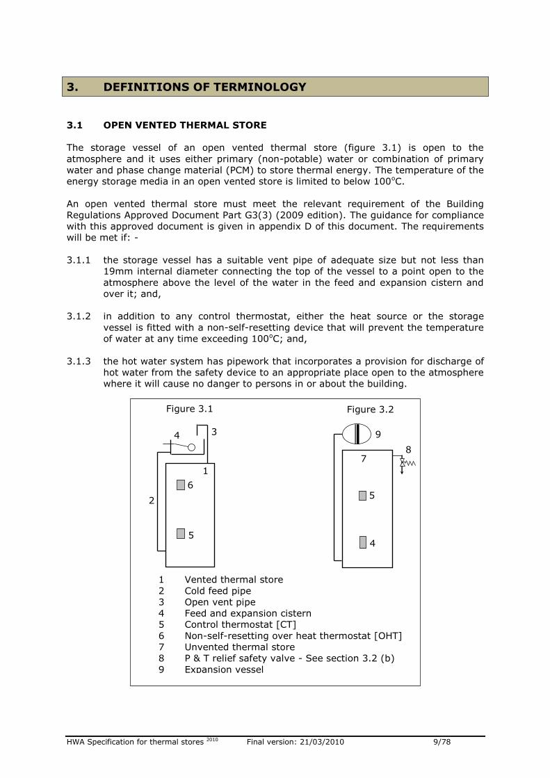
The storage vessel of an open vented thermal store (figure 3.1) is open to the
atmosphere and it uses either primary (non-potable) water or combination of primary
water and phase change material (PCM) to store thermal energy. The temperature of the
energy storage media in an open vented store is limited to below 100oC.
An open vented thermal store must meet the relevant requirement of the Building
Regulations Approved Document Part G3(3) (2009 edition). The guidance for compliance
with this approved document is given in appendix D of this document. The requirements
will be met if: -
3.1.1 the storage vessel has a suitable vent pipe of adequate size but not less than
19mm internal diameter connecting the top of the vessel to a point open to the
atmosphere above the level of the water in the feed and expansion cistern and
over it; and,
3.1.2 in addition to any control thermostat, either the heat source or the storage
vessel is fitted with a non-self-resetting device that will prevent the temperature
of water at any time exceeding 100oC; and,
3.1.3 the hot water system has pipework that incorporates a provision for discharge of
hot water from the safety device to an appropriate place open to the atmosphere
where it will cause no danger to persons in or about the building.
1
2
3 4
5
6
1 Vented thermal store
2 Cold feed pipe
3 Open vent pipe
4 Feed and expansion cistern
5 Control thermostat [CT]
6 Non-self-resetting over heat thermostat [OHT]
7 Unvented thermal store
8 P & T relief safety valve - See section 3.2 (b)
9 Expansion vessel
Figure 3.2
7
9
4
5
8
Figure 3.1
HWA Specification for thermal stores 2010 Final version: 21/03/2010 10/78
3.2 UNVENTED THERMAL STORE
The storage vessel of an unvented thermal store (figure 3.2) is not open to the
atmosphere and it uses either primary (non-potable) water or combination of primary
water and phase change material (PCM) to store thermal energy. The temperature of the
energy storage media in an unvented store is limited to below 100oC.
An unvented thermal store must also comply with the relevant requirement of the
Building Regulations Approved Document Part G3(3) (2009 edition). This will be met if in
addition to any control thermostat provided to control the temperature of the stored
water to a desired temperature, the unvented thermal store should incorporate a
minimum of two temperature activated safety devices operating independently in series.
Further guidance on unvented thermal stores is given in appendix D, normally:
3.2.1 A non-self-resetting energy cut-out to disconnect the supply of heat to the
storage vessel in the event of storage system overheating; and plus either an
option (b) or an option (c).
3.2.2 If the unvented thermal storage system is fitted with an approved device (e.g.
RPZ Valve [1]) which automatically replenishes the stored water then either a
temperature relief valve or a combined temperature and pressure relief valve
located directly on a storage vessel, such that the stored water does not exceed
100oC.
Note: [1] Since the introduction of the Water Supply (Water Fittings) Regulations 1999 in England and Wales and the Water Bylaws 2000 in Scotland, it is permitted to use the backflow prevention device instead of an air gap for category 1 fluid, at certain risk levels. A reduced pressure zone (RPZ) valve is an example of such backflow prevention device. [2] The automatic filling and topping devices are usually set at low flow rates and therefore will limit the discharge rate from the P&T valve and hence the power input of the heat source. This will have to be determined during the certification process.
3.2.3 If the unvented thermal storage system has no provision to automatically
replenish the stored water then there should be a second non-self-resetting
energy cut-out, which stops the flow of energy from the heat source to the
thermal store using alternative and independent of method (a), such that the
stored water does not exceed 100oC.
3.3 WORKING PRESSURES (HEAD)
The working pressure or working head is defined as the maximum pressure to which the
storage vessel or a heat exchanger of a thermal store can be subjected to normal use.
3.4 HEAT LOSS FACTOR ( QHLF )
The heat loss factor, QHLF, is defined as the ‘standby heat loss rate’ from a thermal store
or an appliance based on it that has been measured at the specified test conditions and
using the test procedure specified in this document.
3.5 STORE ZONES AND STORAGE VOLUMES
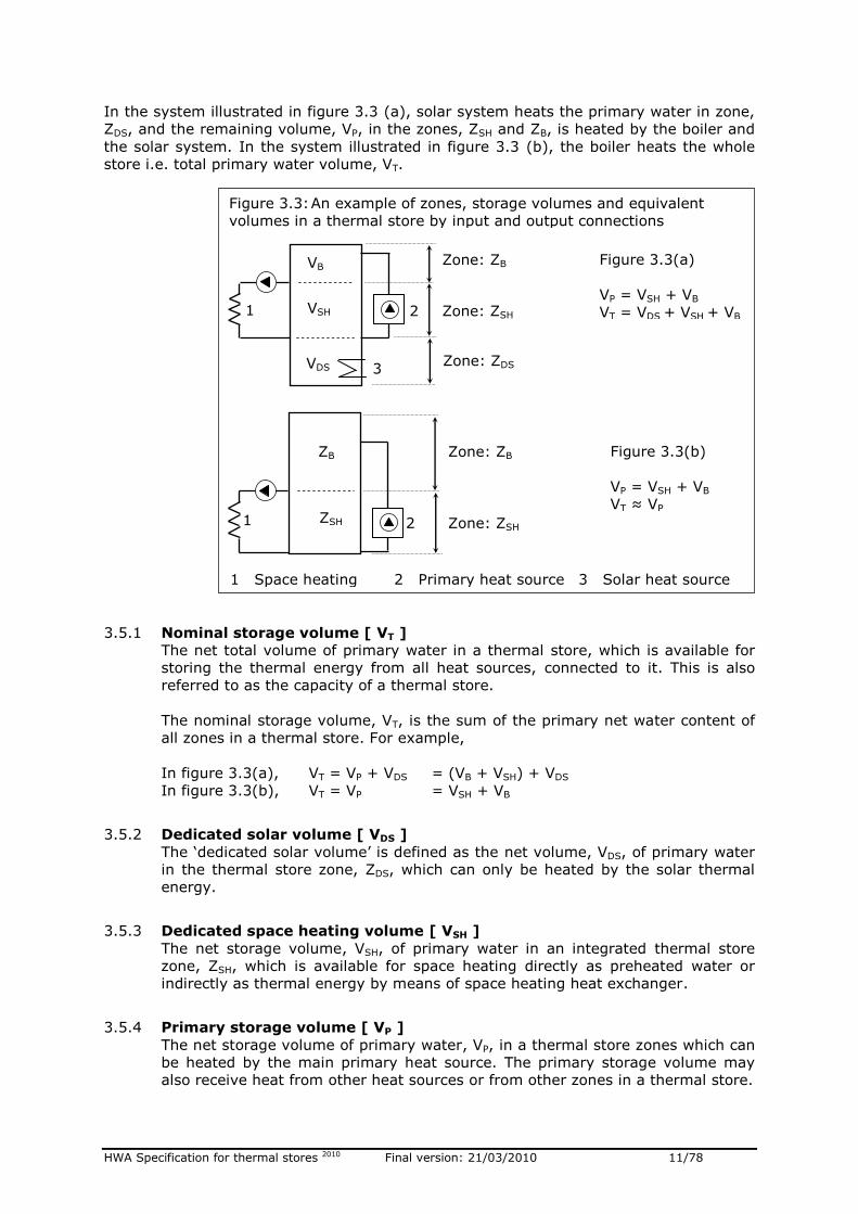
As illustrated in figure 3.3, the hydraulic input and output connection arrangement
creates different functioning zones in a thermal store. The water content, volume or the
capacities associated with different zone in a thermal store are described below.
HWA Specification for thermal stores 2010 Final version: 21/03/2010 11/78
In the system illustrated in figure 3.3 (a), solar system heats the primary water in zone,
ZDS, and the remaining volume, VP, in the zones, ZSH and ZB, is heated by the boiler and
the solar system. In the system illustrated in figure 3.3 (b), the boiler heats the whole
store i.e. total primary water volume, VT.
3.5.1 Nominal storage volume [ VT ]
The net total volume of primary water in a thermal store, which is available for
storing the thermal energy from all heat sources, connected to it. This is also
referred to as the capacity of a thermal store.
The nominal storage volume, VT, is the sum of the primary net water content of
all zones in a thermal store. For example,
In figure 3.3(a), VT = VP + VDS = (VB + VSH) + VDS
In figure 3.3(b), VT = VP = VSH + VB
3.5.2 Dedicated solar volume [ VDS ]
The ‘dedicated solar volume’ is defined as the net volume, VDS, of primary water
in the thermal store zone, ZDS, which can only be heated by the solar thermal
energy.
3.5.3 Dedicated space heating volume [ VSH ]
The net storage volume, VSH, of primary water in an integrated thermal store
zone, ZSH, which is available for space heating directly as preheated water or
indirectly as thermal energy by means of space heating heat exchanger.
3.5.4 Primary storage volume [ VP ]
The net storage volume of primary water, VP, in a thermal store zones which can
be heated by the main primary heat source. The primary storage volume may
also receive heat from other heat sources or from other zones in a thermal store.
1 Space heating 2 Primary heat source 3 Solar heat source
Figure 3.3(a)
VP = VSH + VB
VT = VDS + VSH + VB
ZSH
ZB
1
VDS
VSH
VB
1 2
3
Figure 3.3(b)
VP = VSH + VB
VT ≈ VP
Figure 3.3: An example of zones, storage volumes and equivalent
volumes in a thermal store by input and output connections
Zone: ZDS
Zone: ZSH
Zone: ZB
2 Zone: ZSH
Zone: ZB
HWA Specification for thermal stores 2010 Final version: 21/03/2010 12/78
3.5.5 Primary storage volume [ VB ]
As illustrated in figure, the primary water volume, VB, in zone ZB, is not used for
space heating. In an integrated thermal store, this may be reserved for
producing domestic hot water.
3.6 EQUIVALENT STORAGE VOLUMES IN A THERMAL STORE
If a zone, ZN, in a thermal store contains water only, then its energy storage capacity is
proportional to the net volume of water, VZ, in that zone. However, if zone, Z, contains
mixture of water and phase change material (PCM) then its energy storage capacity is
not directly related to its volume.
In this document, if a zone, Z, in a thermal store contains PCM, then its equivalent
volume of water, VEZ, is calculated using equation 3.1. This equation calculates the
energy storage capacity of the zone in equivalent water content. This allows the
performance of the stores with and without PCM to be measured and compared using the
same reference parameters.
The equation 3.1 can be used to calculate equivalent volume of water for all zones in a
thermal store which contain PCM i.e. VET, VEDS, VEP, VESH which correspond to the thermal
store zone volumes, VT, VDS, VP, VSH without PCM.
VEZ = [VWZ/VZ] + mZ[CPS(TM – T0) + LH + CPL(T1 – TM)]/[VZ ρ Cp(T1 – T0)] ---- 3.1
Where :
VEZ =Equivalent volume of water in zone, Z, with PCM [l]
VWZ = Net volume of water in zone, Z, with PCM [l]
VZ = Net volume of water in zone, Z, without PCM [l]
mZ = Mass of PCM in zone, Z [kg]
Cp = Average specific heat of water between T0 and T1 [J/Kg.K]
ρ = Average density of water between T0 and T1 [kg/l]
CPS = Specific heat of PCM in solid phase [J/Kg.K]
CPL = Latent heat of PCM in liquid phase [J/kg.K]
LH = Latent heat of PCM [J/kg]
TM = Phase change temperature of PCM [oC]
T0 = Lower reference temperature (= 20oC) [oC]
T1 = Upper refernce temperature [oC]
3.7 PRIMARY HEAT EXCHANGER
A heat exchanger in zone, ZP, in an indirect thermal store that is used to transfers the
heat from a primary heat source e.g. a boiler circuit, to the energy storage media (e.g.
primary water) in a thermal store.
3.8 SPACE HEATING HEAT EXCHANGER
A heat exchanger in an integrated thermal store zone, ZSH, that is used to transfers the
thermal energy from the storage media in a thermal store to the space heating circuit.
3.9 SOLAR HEAT EXCHANGER
An internal heat exchanger inside a thermal store in a dedicated solar zone ‘VDS’, or an
external heat exchanger, that is used to transfers the thermal energy from the solar
heating system to the storage media in a thermal store.
HWA Specification for thermal stores 2010 Final version: 21/03/2010 13/78
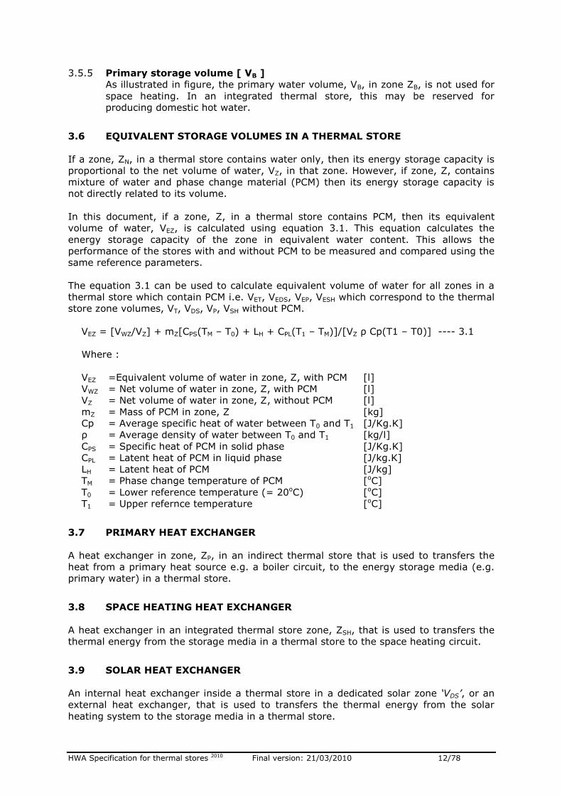
3.10 DOMESTIC HOT WATER (DHW) HEAT EXCHANGER
An integrated or a hot water thermal store may be fitted with an external or an internal
dhw heat exchanger and this can be either forced or natural convection type. Commonly
used types are described below.
3.10.1 Natural convection hot water heat exchanger
A water to water heat exchanger inside a thermal store (figure 3.4) which
transfers heat from the primary water to the domestic hot water during a hot
water draw-off without using motive power (e.g. a pump) to circulate the
primary water.
3.10.2 Forced convection hot water heat exchanger
A water to water heat exchanger outside (figure 3.5) or inside a thermal store
(figure 3.6) which requires a motive power (e.g. a pump) to circulate the
primary water through the heat exchanger during a hot water draw-off. The
pump used for circulating the primary water through the heat exchanger during
the hot water draw-off may also act as a boiler and/or a heating circuit pump.
3.11 DOMESTIC HOT WATER OUTLET TEMPERATURE CONTROLLER
A device (e.g. a thermostatic non-electric blending valve) which is fitted to thermal store
for regulating the domestic hot water outlet temperature and which also limits the ‘hot
slug’ of water reaching the outlets.
1 Thermal store
2 Primary water
3 Mains cold water inlet
4 Hot water to taps
5 Hot water heat exchanger 6 Primary pump
2
4
3
5
1
Figure 3.4: Natural convection
Hot water heat exchanger
2
4
3
5
1
Figure 3.6: Forced convection
internal hot water heat exchanger
6
Figure 3.5: Forced convection
external hot water heat exchanger
6
4
3
1
2
5
HWA Specification for thermal stores 2010 Final version: 21/03/2010 14/78
3.12 HOT SLUG
The volume of hot water above 60oC passed during a domestic hot water draw-off when
the temperature-regulating device is set to control the outlet temperature at 50 - 55oC.
3.13 DATA BADGE
A permanent badge fitted to a thermal store, which gives information about safety,
identification and essential performance information for the service and installation
engineers.
3.14 INSTALLATION AND DESIGN MANUAL
One or more comprehensive sets of documents supplied with every thermal store
containing system design, installation, performance, application and service information
for that store.
3.15 STORE THERMOSTATS/SENSORS
One or more thermostats or temperature sensors, which are used to control the
temperature of the primary water in the thermal store by controlling the operation of the
heat sources, for example: -
Primary heat source e.g. a boiler
Standby i.e. backup heat source e.g. immersion heater
Secondary heat source e.g. Solar thermal system, wood burning stove
HWA Specification for thermal stores 2010 Final version: 21/03/2010 15/78
4. DEFINITION OF THERMAL STORES
4.1 INTEGRATED THERMAL STORE ( ITS )
4.1.1 A thermal store that is designed to store primary (non-potable) hot water which
can be used indirectly for producing domestic hot water and either directly or
indirectly for space heating.
4.1.2 The ‘ITS’ may also contain phase change material (PCM) in addition to the
primary for storing thermal energy and the temperature of the primary water in
an ‘ITS’ is limited to below 100oC.
4.1.3 In an ‘ITS’ the domestic hot water (dhw) is heated instantaneously by
transferring the stored heat to the mains water flowing through the dhw heat
exchanger. The dhw heat exchanger may be internal or external type as
described in section 3.10.
4.1.4 If the ‘ITS’ storage vessel is designed for an open vented system, then it may
have an integral feed and expansion cistern.
4.1.5 Both the vented and the unvented ‘ITS’ must comply with the requirements of
the relevant sections in the Building Regulations 2000, Approved Document G,
2009 edition. Methods of compliance are specified in section 5.7 of this
document.
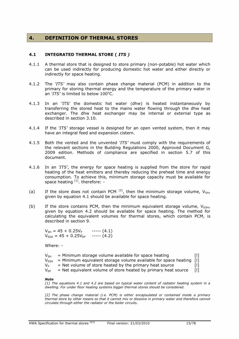
4.1.6 In an ‘ITS’, the energy for space heating is supplied from the store for rapid
heating of the heat emitters and thereby reducing the preheat time and energy
consumption. To achieve this, minimum storage capacity must be available for
space heating [1]. therefore: -
(a) If the store does not contain PCM [2], then the minimum storage volume, VSH,
given by equation 4.1 should be available for space heating.
(b) If the store contains PCM, then the minimum equivalent storage volume, VESH,
given by equation 4.2 should be available for space heating. The method for
calculating the equivalent volumes for thermal stores, which contain PCM, is
described in section 9.
VSH = 45 + 0.25VP ----- (4.1)
VESH = 45 + 0.25VEP ----- (4.2)
Where: -
VSH = Minimum storage volume available for space heating [l]
VESH = Minimum equivalent storage volume available for space heating [l]
VP = Net volume of store heated by the primary heat source [l]
VEP = Net equivalent volume of store heated by primary heat source [l]
Note [1] The equations 4.1 and 4.2 are based on typical water content of radiator heating system in a
dwelling. For under floor heating systems bigger thermal stores should be considered. [2] The phase change material (i.e. PCM) is either encapsulated or contained inside a primary thermal store by other means so that it cannot mix or dissolve in primary water and therefore cannot circulate through either the radiator or the boiler circuits.
HWA Specification for thermal stores 2010 Final version: 21/03/2010 16/78
4.1.7 In addition to heating by the main primary heat source, the ‘ITS’ may also be
heated directly or indirectly by an external or internal secondary/standby heat
source (e.g. an immersion heater).
4.2 DIRECT AND INDIRECT INTEGRATED THERMAL STORE (DITS & IDITS)
4.2.1 A direct integrated thermal store, DITS, is an integrated thermal store which
complies with the requirements of section 4.1 and in which the energy storage
medium (e.g. primary water or combination of primary water and phase change
material i.e. PCM) is heated directly by an internal or an external main heat
source e.g. a gas boiler.
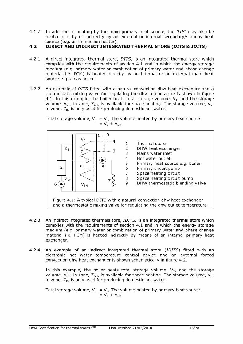
4.2.2 An example of DITS fitted with a natural convection dhw heat exchanger and a
thermostatic mixing valve for regulating the dhw temperature is shown in figure
4.1. In this example, the boiler heats total storage volume, VT, and the storage
volume, VSH, in zone, ZSH, is available for space heating. The storage volume, VB,
in zone, ZB, is only used for producing domestic hot water.
Total storage volume, VT = VP, The volume heated by primary heat source
= VB + VSH
4.2.3 An indirect integrated thermals tore, IDITS, is an integrated thermal store which
complies with the requirements of section 4.1 and in which the energy storage
medium (e.g. primary water or combination of primary water and phase change
material i.e. PCM) is heated indirectly by means of an internal primary heat
exchanger.
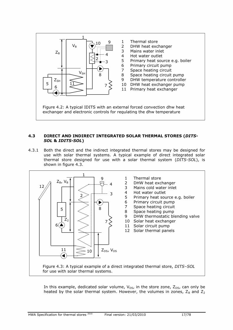
4.2.4 An example of an indirect integrated thermal store (IDITS) fitted with an
electronic hot water temperature control device and an external forced
convection dhw heat exchanger is shown schematically in figure 4.2.
In this example, the boiler heats total storage volume, VT, and the storage
volume, VSH, in zone, ZSH, is available for space heating. The storage volume, VB,
in zone, ZB, is only used for producing domestic hot water.
Total storage volume, VT = VP, The volume heated by primary heat source
= VB + VSH
Figure 4.1: A typical DITS with a natural convection dhw heat exchanger
and a thermostatic mixing valve for regulating the dhw outlet temperature
3
4
6 7
9
8
1
2
VB
VSH
5
1 Thermal store
2 DHW heat exchanger
3 Mains water inlet
4 Hot water outlet
5 Primary heat source e.g. boiler
6 Primary circuit pump
7 Space heating circuit
8 Space heating circuit pump 9 DHW thermostatic blending valve
ZSH
ZB
HWA Specification for thermal stores 2010 Final version: 21/03/2010 17/78
4.3 DIRECT AND INDIRECT INTEGRATED SOLAR THERMAL STORES (DITS-
SOL & IDITS-SOL)
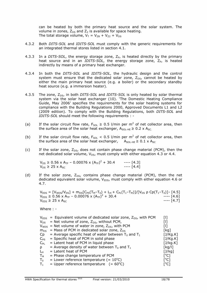
4.3.1 Both the direct and the indirect integrated thermal stores may be designed for
use with solar thermal systems. A typical example of direct integrated solar
thermal store designed for use with a solar thermal system (DITS-SOL), is
shown in figure 4.3.
In this example, dedicated solar volume, VDS, in the store zone, ZDS, can only be
heated by the solar thermal system. However, the volumes in zones, ZB and Z2
Figure 4.2: A typical IDITS with an external forced convection dhw heat
exchanger and electronic controls for regulating the dhw temperature
6 7
8
1
2
VB
VSH
3
4
10
5
1 Thermal store
2 DHW heat exchanger
3 Mains water inlet
4 Hot water outlet
5 Primary heat source e.g. boiler
6 Primary circuit pump
7 Space heating circuit
8 Space heating circuit pump
9 DHW temperature controller
10 DHW heat exchanger pump 11 Primary heat exchanger
9
ZB
ZSH 11
Figure 4.3: A typical example of a direct integrated thermal store, DITS–SOL
for use with solar thermal systems.
3
4
6 7
9
8
1
2
Z2
5
10 11
12
1 Thermal store
2 DHW heat exchanger
3 Mains cold water inlet
4 Hot water outlet
5 Primary heat source e.g. boiler
6 Primary circuit pump
7 Space heating circuit
8 Space heating pump
9 DHW thermostatic blending valve
10 Solar heat exchanger
11 Solar circuit pump 12 Solar thermal panels
ZDS, VDS
ZB, VB
HWA Specification for thermal stores 2010 Final version: 21/03/2010 18/78
can be heated by both the primary heat source and the solar system. The
volume in zones, ZDS and Z2 is available for space heating.
The total storage volume, VT = VZB + VZ2 + VDS
4.3.2 Both DITS-SOL and IDITS-SOL must comply with the generic requirements for
an integrated thermal stores listed in section 4.1.
4.3.3 In a DITS-SOL, the energy storage zone, ZP, is heated directly by the primary
heat source and in an IDITS-SOL, the energy storage zone, ZP, is heated
indirectly by means of a primary heat exchanger.
4.3.4 In both the DITS-SOL and IDITS-SOL, the hydraulic design and the control
system must ensure that the dedicated solar zone, ZDS, cannot be heated by
either the main primary heat source (e.g. a boiler) or the secondary standby
heat source (e.g. a immersion heater).
4.3.5 The zone, ZDS, in both DITS-SOL and IDITS-SOL is only heated by solar thermal
system via the solar heat exchanger (10). ‘The Domestic Heating Compliance
Guide, May 2006’ specifies the requirements for the solar heating systems for
compliance with the Building Regulations 2000, Approved Documents L1 and L2
(2009 edition). To comply with the Building Regulations, both DITS-SOL and
IDITS-SOL should meet the following requirements : -
(a) If the solar circuit flow rate, FSOL ≥ 0.5 l/min per m2 of net collector area, then
the surface area of the solar heat exchanger, ASOL-HE ≥ 0.2 x ASC.
(b) If the solar circuit flow rate, FSOL < 0.5 l/min per m2 of net collector area, then
the surface area of the solar heat exchanger, ASOL-HE ≥ 0.1 x ASC
(c) If the solar zone, ZDS, does not contain phase change material (PCM), then the
net dedicated solar volume, VDS, must comply with either equation 4.3 or 4.4.
VDS ≥ 0.56 x ATF – 0.00076 x (ATF)2 + 30.4 ---- [4.3]
VDS ≥ 25 x ASC ---- [4.4]
(d) If the solar zone, ZDS, contains phase change material (PCM), then the net
dedicated equivalent solar volume, VEDS, must comply with either equation 4.6 or
4.7.
VEDS = [VWDS/VDS] + mDS[CPS(TM–T0) + LH + CPL(T1–TM)]/[VDS ρ Cp(T1–T0)] - [4.5]
VEDS ≥ 0.56 x ATF – 0.00076 x (ATF)2 + 30.4 ---- [4.6]
VEDS ≥ 25 x ASC ---- [4.7]
Where : -
VEDS = Equivalent volume of dedicated solar zone, ZDS, with PCM [l]
VDS = Net volume of zone, ZDS, without PCM, [l]
VWDS = Net volume of water in zone, ZDS, with PCM [l]
mDS = Mass of PCM in dedicated solar zone, ZDS [kg]
Cp = Average specific heat of water between T0 and T1 [J/Kg.K]
CPS = Specific heat of PCM in solid phase [J/Kg.K]
CPL = Latent heat of PCM in liquid phase [J/kg.K]
ρ = Average density of water between T0 and T1 [kg/l]
LH = Latent heat of PCM [J/kg]
TM = Phase change temperature of PCM [oC]
T0 = Lower reference temperature (= 10oC) [oC]
T1 = Upper reference temperature (= 60oC) [oC]
HWA Specification for thermal stores 2010 Final version: 21/03/2010 19/78
ATF = Maximum total floor area of a dwelling specified for the store [m2]
ASOL-HE = Surface area of the solar heat exchanger [m2]
ASC = Net surface area of the solar collector specified for the store [m2]
FSOL `= Solar circuit flow rate per m2 of net collector area [l/min]
4.3.6 Appliances based on either DITS-SOL or IDITS-SOL will use solar energy
accumulated in a thermal store for space heating and for producing domestic hot
water. Therefore in order to maximise the utilisation of solar energy: -
(a) The control system should not allow the primary heat source to operate if solar
gains are sufficient to supply heating and hot water requirements. Some of the
means of achieving this are: -
Factory fitted integrated and intelligent control system, which only allows the
primary heat source (e.g. a boiler) to fire if the input from the solar system is
not sufficient to meet the demands for heating and hot water.
Using either the ‘thermal startifiers’ inside a thermal store or combination of
hydraulic design and controls to prioritise the heating of the store from top to
bottom when solar energy is available.
The information should be provided for the installer to implement the control
strategy on site and for the occupant on how best to use the system.
(b) The domestic hot water heat exchanger should be designed such that the heat is
removed from the dedicated solar zone during a hot water draw-off.
Note:
The water content of a domestic hot water heat exchanger is usually small (2 – 10 litres) and therefore the stagnant time of domestic hot water in the heat exchanger is very low compared to a hot water cylinder. This combined with higher primary water temperature, it not necessary to provide
facility for pasteurising the solar thermal stores.
4.4 DIRECT & INDIRECT HOT WATER THERMAL STORES [DHWTS & IDHWTS]
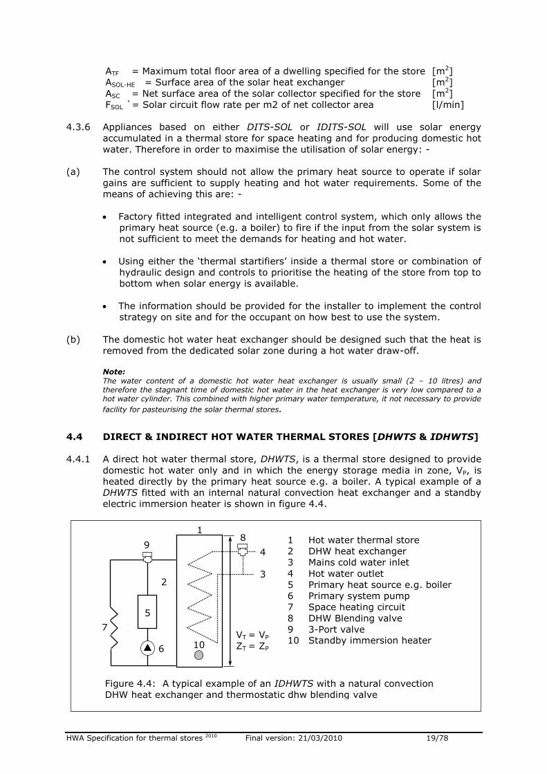
4.4.1 A direct hot water thermal store, DHWTS, is a thermal store designed to provide
domestic hot water only and in which the energy storage media in zone, VP, is
heated directly by the primary heat source e.g. a boiler. A typical example of a
DHWTS fitted with an internal natural convection heat exchanger and a standby
electric immersion heater is shown in figure 4.4.
3
4
6
7
8
1
2
5
9
Figure 4.4: A typical example of an IDHWTS with a natural convection
DHW heat exchanger and thermostatic dhw blending valve
VT = VP
ZT = ZP
10
1 Hot water thermal store
2 DHW heat exchanger
3 Mains cold water inlet
4 Hot water outlet
5 Primary heat source e.g. boiler
6 Primary system pump
7 Space heating circuit
8 DHW Blending valve
9 3-Port valve 10 Standby immersion heater
HWA Specification for thermal stores 2010 Final version: 21/03/2010 20/78
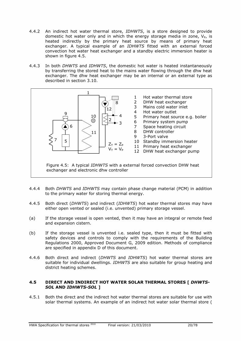
4.4.2 An indirect hot water thermal store, IDHWTS, is a store designed to provide
domestic hot water only and in which the energy storage media in zone, VP, is
heated indirectly by the primary heat source by means of primary heat
exchanger. A typical example of an IDHWTS fitted with an external forced
convection hot water heat exchanger and a standby electric immersion heater is
shown in figure 4.5.
4.4.3 In both DHWTS and IDHWTS, the domestic hot water is heated instantaneously
by transferring the stored heat to the mains water flowing through the dhw heat
exchanger. The dhw heat exchanger may be an internal or an external type as
described in section 3.10.
4.4.4 Both DHWTS and IDHWTS may contain phase change material (PCM) in addition
to the primary water for storing thermal energy.
4.4.5 Both direct (DHWTS) and indirect (IDHWTS) hot water thermal stores may have
either open vented or sealed (i.e. unvented) primary storage vessel.
(a) If the storage vessel is open vented, then it may have an integral or remote feed
and expansion cistern.
(b) If the storage vessel is unvented i.e. sealed type, then it must be fitted with
safety devices and controls to comply with the requirements of the Building
Regulations 2000, Approved Document G, 2009 edition. Methods of compliance
are specified in appendix D of this document.
4.4.6 Both direct and indirect (DHWTS and IDHWTS) hot water thermal stores are
suitable for individual dwellings. IDHWTS are also suitable for group heating and
district heating schemes.
4.5 DIRECT AND INDIRECT HOT WATER SOLAR THERMAL STORES [ DHWTS-
SOL AND IDHWTS-SOL ]
4.5.1 Both the direct and the indirect hot water thermal stores are suitable for use with
solar thermal systems. An example of an indirect hot water solar thermal store (
6
1
2
3
4
12
5
7
9
Figure 4.5: A typical IDHWTS with a external forced convection DHW heat
exchanger and electronic dhw controller
11
8
10
1 Hot water thermal store
2 DHW heat exchanger
3 Mains cold water inlet
4 Hot water outlet
5 Primary heat source e.g. boiler
6 Primary system pump
7 Space heating circuit
8 DHW controller
9 3-Port valve
10 Standby immersion heater
11 Primary heat exchanger 12 DHW heat exchanger pump
ZT = ZP
VT = VP
HWA Specification for thermal stores 2010 Final version: 21/03/2010 21/78
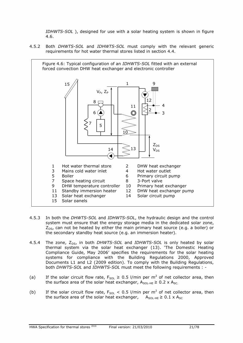
IDHWTS-SOL ), designed for use with a solar heating system is shown in figure
4.6.
4.5.2 Both DHWTS-SOL and IDHWTS-SOL must comply with the relevant generic
requirements for hot water thermal stores listed in section 4.4.
4.5.3 In both the DHWTS-SOL and IDHWTS-SOL, the hydraulic design and the control
system must ensure that the energy storage media in the dedicated solar zone,
ZDS, can not be heated by either the main primary heat source (e.g. a boiler) or
the secondary standby heat source (e.g. an immersion heater).
4.5.4 The zone, ZDS, in both DHWTS-SOL and IDHWTS-SOL is only heated by solar
thermal system via the solar heat exchanger (13). ‘The Domestic Heating
Compliance Guide, May 2006’ specifies the requirements for the solar heating
systems for compliance with the Building Regulations 2000, Approved
Documents L1 and L2 (2009 edition). To comply with the Building Regulations,
both DHWTS-SOL and IDHWTS-SOL must meet the following requirements : -
(a) If the solar circuit flow rate, FSOL ≥ 0.5 l/min per m2 of net collector area, then
the surface area of the solar heat exchanger, ASOL-HE ≥ 0.2 x ASC.
(b) If the solar circuit flow rate, FSOL < 0.5 l/min per m2 of net collector area, then
the surface area of the solar heat exchanger, ASOL-HE ≥ 0.1 x ASC
Figure 4.6: Typical configuration of an IDHWTS-SOL fitted with an external
forced convection DHW heat exchanger and electronic controller
1 Hot water thermal store 2 DHW heat exchanger
3 Mains cold water inlet 4 Hot water outlet
5 Boiler 6 Primary circuit pump
7 Space heating circuit 8 3-Port valve
9 DHW temperature controller 10 Primary heat exchanger
11 Standby immersion heater 12 DHW heat exchanger pump
13 Solar heat exchanger 14 Solar circuit pump
15 Solar panels
6
1
2
3
4
12
5
7
8
15
10
9
14 13
VP, ZP
ZDS
VDS
11
HWA Specification for thermal stores 2010 Final version: 21/03/2010 22/78
(c) If the solar zone, ZDS, does not contain phase change material (PCM), then the
dedicated solar volume, VDS, must comply with either equation 4.8 or equation
4.9.
VDS ≥ 0.56 x ATF – 0.00076 x (ATF)2 + 30.4 ---- [4.8]
VDS ≥ 25 x ASC ---- [4.9]
(d) If the solar zone, ZDS, contains phase change material (PCM), then the
equivalent dedicated solar volume, VEDS, must comply with either equation 4.11
or equation 4.12.
VEDS = [VWDS/VDS]+mDS[CPS(TM–T0)+LH+CPL(T1–TM)]/[VDS ρ Cp(T1–T0)] -- [4.10]
VEDS ≥ 0.56 x ATF – 0.00076 x (ATF)2 + 30.4 -- [4.11]
VEDS ≥ 25 x ASC -- [4.12]
Where : -
VEDS = Equivalent volume of dedicated solar zone, ZDS, with PCM [l]
VDS = Net volume of zone, ZDS, without PCM, [l]
VWDS = Net volume of water in zone, ZDS, with PCM [l]
mDS = Mass of PCM in dedicated solar zone, ZDS [kg]
Cp = Average specific heat of water between T0 and T1 [J/Kg.K]
CPS = Specific heat of PCM in solid phase [J/Kg.K]
CPL = Latent heat of PCM in liquid phase [J/kg.K]
ρ = Average density of water between T0 and T1 [kg/l]
LH = Latent heat of PCM [J/kg]
TM = Phase change temperature of PCM [oC]
T0 = Lower reference temperature (= 10oC) [oC]
T1 = Upper reference temperature (= 60oC) [oC]
ATF = Maximum total floor area of a dwelling specified for the store [m2]
ASOL-HE = Surface area of the solar heat exchanger [m2]
ASC = Net surface area of the solar collector specified for the store [m2]
FSOL = Solar circuit flow rate per m2 of net collector area [l/min]
4.5.5 The heating systems based on either DHWTS-SOL or IDHWTS-SOL will use solar
energy accumulated in a thermal store for producing domestic hot water only. In
order to maximise the utilisation of solar energy: -
(a) The control system should not allow the primary heat source to operate if solar
gains are sufficient to supply hot water requirements. Some of the means of
achieving this are: -
Factory fitted integrated and intelligent control system, which only allows the
primary heat source (e.g. a boiler) to fire if the input from the solar system is
not sufficient to meet the demands for heating and hot water.
Using either ‘thermal startifiers’ inside a thermal store or combination of
hydraulic design and controls to prioritise the heating of the store from top to
bottom when solar energy is available.
The information should be provided for the installer to implement the control
strategy on site and for the occupant on how best to use the system.
(b) The domestic hot water heat exchanger should be designed such that the heat is
removed from the dedicated solar zone during a hot water draw-off.
Note:
HWA Specification for thermal stores 2010 Final version: 21/03/2010 23/78
The water content of a domestic hot water heat exchanger is usually small (2 – 10 litres) and therefore the stagnant time of domestic hot water in the heat exchanger is very low compared to a hot water cylinder. This combined with higher primary water temperature, it not necessary to provide facility for pasteurising the solar thermal stores.
4.6 DIRECT AND INDIRECT BUFFER STORES (DBS AND IDBS)
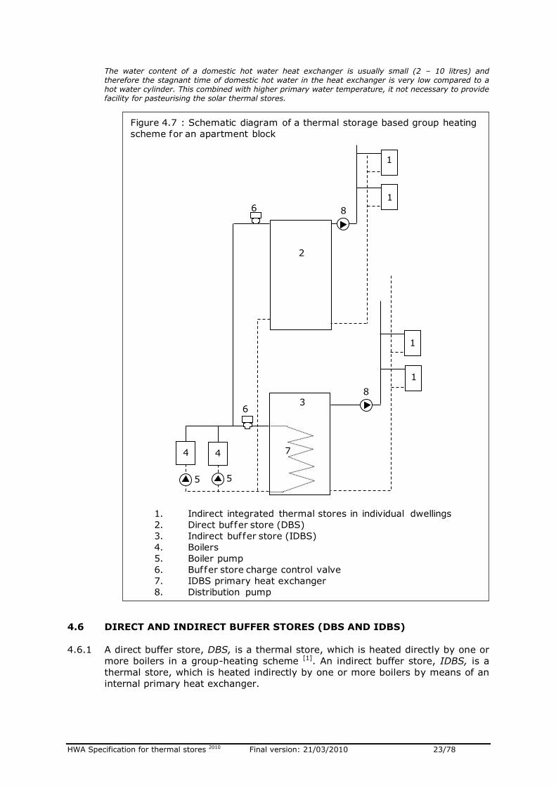
4.6.1 A direct buffer store, DBS, is a thermal store, which is heated directly by one or
more boilers in a group-heating scheme [1]. An indirect buffer store, IDBS, is a
thermal store, which is heated indirectly by one or more boilers by means of an
internal primary heat exchanger.
Figure 4.7 : Schematic diagram of a thermal storage based group heating
scheme for an apartment block
1. Indirect integrated thermal stores in individual dwellings
2. Direct buffer store (DBS)
3. Indirect buffer store (IDBS)
4. Boilers
5. Boiler pump
6. Buffer store charge control valve
7. IDBS primary heat exchanger
8. Distribution pump
4 4
5 5
1
1
1
1
2
3
6
6
8
8
7
HWA Specification for thermal stores 2010 Final version: 21/03/2010 24/78
In these heating systems, DBS and IDBS are used for supplying primary hot
water to thermal stores located in the individual dwellings.
4.6.2 Both direct and indirect buffer stores (DBS and IDBS) may contain phase change
material [2] (PCM) in addition to the primary water for storing thermal energy.
4.6.3 Both DBS and IDBS may have either an open vented or a sealed (i.e. unvented)
primary storage vessel. However, both unvented and vented buffer stores must
comply with the requirements of the relevant sections in ‘The Building
Regulations 2000, Approved Document G, 2009 edition’. Methods of compliance
are specified in section 5.7 of this document.
4.6.4 If the storage vessel is open vented, then it may only have a remote feed and
expansion cistern. However, it can be used to supply stores in the apartments at
higher levels by means of intermediate heat exchangers.
4.6.5 One or more buffer store thermostats control the operation of central boilers in a
thermal storage group-heating scheme. A typical schematic arrangement of a
group-heating scheme is shown in figure 4.7.
4.6.6 Both DBS and IDBS do not have built in heat exchangers for supplying domestic
hot water.
Notes [1] The thermal storage group heating systems - a separate publication [2] The phase change material (i.e. PCM) is either encapsulated or contained inside a primary thermal store by other means so that it cannot mix or dissolve in primary water and therefore cannot circulate through either the radiator or the boiler circuits.
HWA Specification for thermal stores 2010 Final version: 21/03/2010 25/78
5. GENERAL AND PERFORMANCE REQUIREMENTS
5.1 INTEGRATED THERMAL STORES FOR INDIVIDUAL DWELLINGS
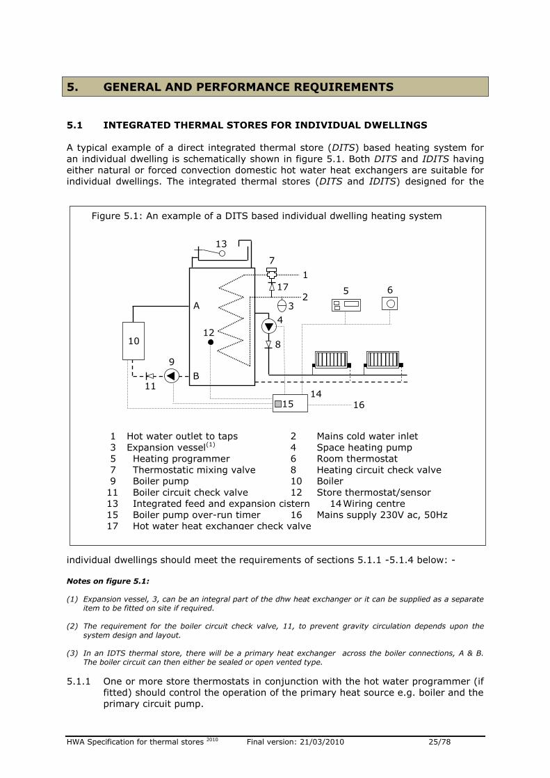
A typical example of a direct integrated thermal store (DITS) based heating system for
an individual dwelling is schematically shown in figure 5.1. Both DITS and IDITS having
either natural or forced convection domestic hot water heat exchangers are suitable for
individual dwellings. The integrated thermal stores (DITS and IDITS) designed for the
individual dwellings should meet the requirements of sections 5.1.1 -5.1.4 below: -
Notes on figure 5.1: (1) Expansion vessel, 3, can be an integral part of the dhw heat exchanger or it can be supplied as a separate
item to be fitted on site if required.
(2) The requirement for the boiler circuit check valve, 11, to prevent gravity circulation depends upon the
system design and layout.
(3) In an IDTS thermal store, there will be a primary heat exchanger across the boiler connections, A & B. The boiler circuit can then either be sealed or open vented type.
5.1.1 One or more store thermostats in conjunction with the hot water programmer (if
fitted) should control the operation of the primary heat source e.g. boiler and the
primary circuit pump.
1 Hot water outlet to taps 2 Mains cold water inlet
3 Expansion vessel(1) 4 Space heating pump
5 Heating programmer 6 Room thermostat
7 Thermostatic mixing valve 8 Heating circuit check valve
9 Boiler pump 10 Boiler
11 Boiler circuit check valve 12 Store thermostat/sensor
13 Integrated feed and expansion cistern 14 Wiring centre
15 Boiler pump over-run timer 16 Mains supply 230V ac, 50Hz
17 Hot water heat exchanger check valve
Figure 5.1: An example of a DITS based individual dwelling heating system
13
4
5 6
14 16
7
2
1
3
8
9
10
11
12
17
A
B
15
HWA Specification for thermal stores 2010 Final version: 21/03/2010 26/78
5.1.2 The user space heating controls e.g. room thermostat and a central heating
programme should control the operation of the central heating pump and not the
operation of the main heat source. A timer based pump overrun control should
be used for the boiler circuit.
Note: The control of both space heating and boiler circuits can be achieved using a conventional 2-channel programmer/controller, but care must be taken to ensure that the boiler is available when only space heating demand is active.
5.1.3 An integrated thermal store can either be supplied with all the components fitted
and wired or full wiring details and a list of recommended components (e.g.
pumps, delay timers) must be provided. Outline specification of common
components is contained in section 8 of this document.
5.1.4 Both DITS and IDITS designed for individual dwellings should meet the following
requirements: -
(a) The relevant generic definition of integrated thermal stores (Section 4.2).
(b) The relevant sub sections of general specification (Section 6).
(c) The relevant sub sections of performance specification (Section 7).
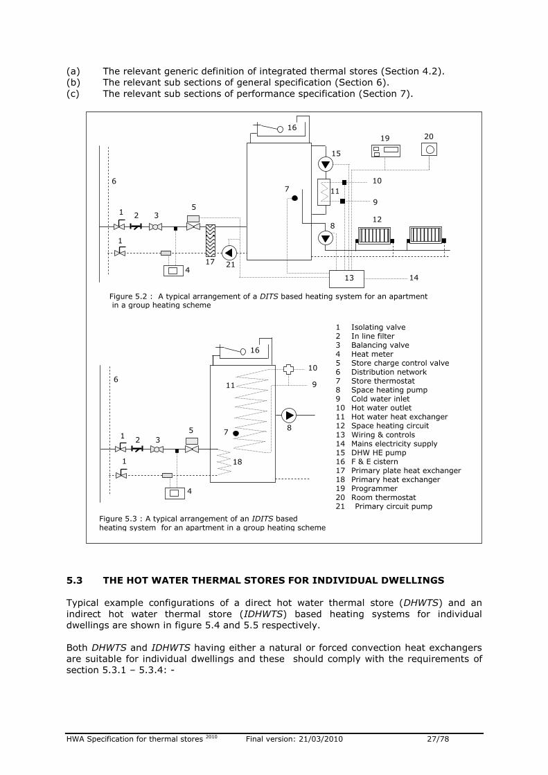
5.2 THE INTEGRATED THERMAL STORES DESIGNED FOR GROUP HEATING
Typical examples of a direct (DITS) and an indirect (IDITS) integrated thermal store
based apartment heating systems for a group heating schemes are shown in figures 5.2
and 5.3 respectively. The DITS and the IDITS designed for a group-heating scheme
should meet the requirements of sections 5.2.1 – 5.2.6 below: -
5.2.1 The integrated thermal store for a group heating scheme does not directly
control the operation of the central heating plant, but the store thermostats
control the operation of the charge control valve and/or a pump.
5.2.2 A DITS designed for a group heating scheme can not have an integral feed and
expansion system provided there is a pressure break (e.g. a plate heat
exchanger) between the group heating system and the DITS as shown in figure
5.2.
5.2.3 The DITS is not normally suitable for use in a group-heating scheme without an
external plate heat exchanger to provide a pressure break as shown
schematically in figure 5.2.
5.2.4 The user space heating controls e.g. room thermostat and a central heating
programme should control the operation of the central heating pump and not the
operation of the charge control device.
5.2.5 The DITS and the IDITS designed for a group heating scheme may be fitted with
a heat metering system. An integrated thermal store for a group heating scheme
can either be supplied with all the components fitted and wired or full wiring
details and a list of recommended components (e.g. pumps, delay timers) must
be provided. Outline specification of common components is contained in section
8 of this document.
5.2.6 Both DITS and IDITS designed for a group heating scheme should comply with
the following requirements: -
HWA Specification for thermal stores 2010 Final version: 21/03/2010 27/78
(a) The relevant generic definition of integrated thermal stores (Section 4.2).
(b) The relevant sub sections of general specification (Section 6).
(c) The relevant sub sections of performance specification (Section 7).
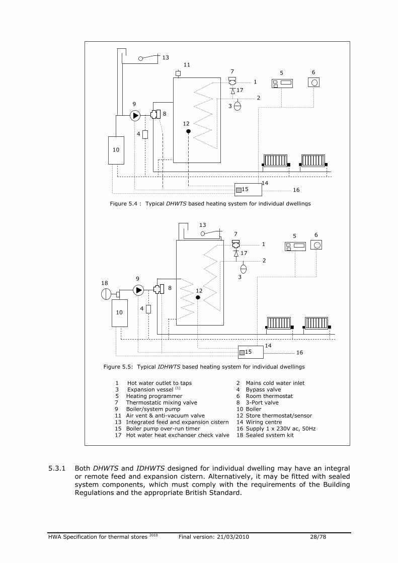
5.3 THE HOT WATER THERMAL STORES FOR INDIVIDUAL DWELLINGS
Typical example configurations of a direct hot water thermal store (DHWTS) and an
indirect hot water thermal store (IDHWTS) based heating systems for individual
dwellings are shown in figure 5.4 and 5.5 respectively.
Both DHWTS and IDHWTS having either a natural or forced convection heat exchangers
are suitable for individual dwellings and these should comply with the requirements of
section 5.3.1 – 5.3.4: -
Figure 5.3 : A typical arrangement of an IDITS based heating system for an apartment in a group heating scheme
1 Isolating valve 2 In line filter 3 Balancing valve 4 Heat meter 5 Store charge control valve 6 Distribution network 7 Store thermostat 8 Space heating pump 9 Cold water inlet 10 Hot water outlet 11 Hot water heat exchanger 12 Space heating circuit
13 Wiring & controls 14 Mains electricity supply 15 DHW HE pump 16 F & E cistern 17 Primary plate heat exchanger 18 Primary heat exchanger 19 Programmer 20 Room thermostat 21 Primary circuit pump
7
16
1
1
2 3
4
5
6
8
9
10
18
Figure 5.2 : A typical arrangement of a DITS based heating system for an apartment in a group heating scheme
11
12 8
9
10 7
19 20
15
14
1
1
2 3
4
5
13
6
16
17 21
11
HWA Specification for thermal stores 2010 Final version: 21/03/2010 28/78
5.3.1 Both DHWTS and IDHWTS designed for individual dwelling may have an integral
or remote feed and expansion cistern. Alternatively, it may be fitted with sealed
system components, which must comply with the requirements of the Building
Regulations and the appropriate British Standard.
1 Hot water outlet to taps 2 Mains cold water inlet 3 Expansion vessel (1) 4 Bypass valve 5 Heating programmer 6 Room thermostat
7 Thermostatic mixing valve 8 3-Port valve 9 Boiler/system pump 10 Boiler 11 Air vent & anti-vacuum valve 12 Store thermostat/sensor 13 Integrated feed and expansion cistern 14 Wiring centre 15 Boiler pump over-run timer 16 Supply 1 x 230V ac, 50Hz 17 Hot water heat exchanger check valve 18 Sealed system kit
Figure 5.4 : Typical DHWTS based heating system for individual dwellings
13
5 6
14
16
7
2
1
3 9
10
12
17
4
8
Figure 5.5: Typical IDHWTS based heating system for individual dwellings
18
13
5 6
14
16
7
2
1
3 9
10
12
17
4
8
11
15
15
HWA Specification for thermal stores 2010 Final version: 21/03/2010 29/78
5.3.2 The operation of the heating system based on a hot water thermal store is
similar to a traditional system based on a hot water cylinder.
If the hot water has priority then the store thermostat controls the operation of
the boiler, system pump and the control (e.g. 3-port diverter) valve.
If a flow share arrangement is used then the user space heating controls e.g. a
room thermostat, store thermostat and heating programmer, should control the
operation of the boiler, system pump and the position of either 2-port zone
valves or position 3-port mid-position valve.
5.3.3 A hot water thermal store can either be supplied with all the components fitted
and wired or full wiring details and a list of recommended components (e.g.
pumps, delay timers) must be provided. Outline specification of common
components is contained in section 8 of this document.
5.3.4 Both DHWTS and IDHWTS designed for individual dwellings should comply with
the following general and performance requirements: -
(a) The relevant generic definition of hot water thermal stores (Section 4.4).
(b) The relevant sub sections of general specification (Section 6).
(c) The relevant sub sections of performance specification (Section 7).
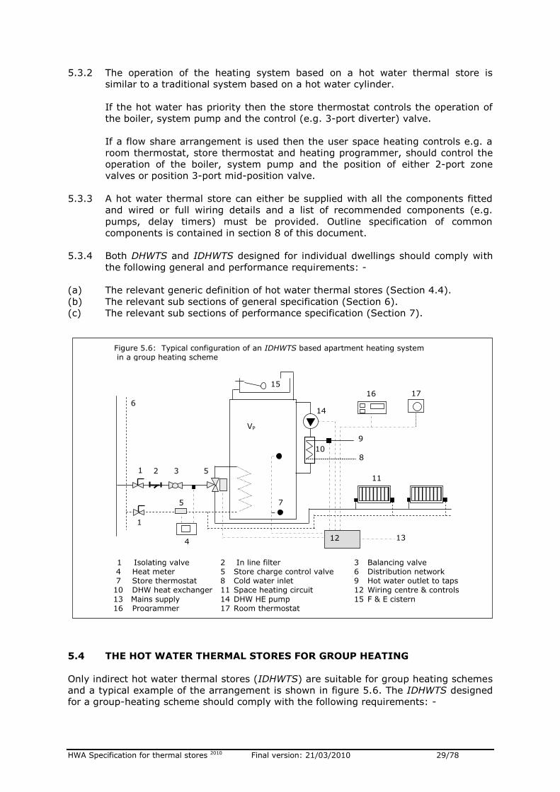
5.4 THE HOT WATER THERMAL STORES FOR GROUP HEATING
Only indirect hot water thermal stores (IDHWTS) are suitable for group heating schemes
and a typical example of the arrangement is shown in figure 5.6. The IDHWTS designed
for a group-heating scheme should comply with the following requirements: -
VP
10
11
8
9
7
16 17
14
13
15
1
1
2 3
5
4
5
12
6
Figure 5.6: Typical configuration of an IDHWTS based apartment heating system in a group heating scheme
1 Isolating valve 2 In line filter 3 Balancing valve 4 Heat meter 5 Store charge control valve 6 Distribution network
7 Store thermostat 8 Cold water inlet 9 Hot water outlet to taps 10 DHW heat exchanger 11 Space heating circuit 12 Wiring centre & controls
13 Mains supply 14 DHW HE pump 15 F & E cistern 16 Programmer 17 Room thermostat
HWA Specification for thermal stores 2010 Final version: 21/03/2010 30/78
5.4.1 The IDHWTS does not control the operation of the central heating plant directly
but the store thermostat controls the operation of the charge control valve.
5.4.2 The IDHWTS designed for a group-heating scheme may be fitted with a heat
metering system.
5.4.3 IDHWTS for a group-heating scheme can either be supplied with all the
components fitted and wired or full wiring details and a list of recommended
components must be provided. Outline specification of common components is
contained in section 8 of this document.
5.4.4 The IDHWTS designed for a group heating scheme should comply with the
following general and performance requirements: -
(a) The relevant generic definition of hot water thermal stores (Section 4.4).
(b) The relevant sub sections of general specification (Section 6).
(c) The relevant sub sections of performance specification (Section 7).
5.4.5 When an IDHWTS is used in high-rise (e.g. tower block) group heating scheme,
a pressure break should be installed to control the primary heat exchanger
operating pressure within design parameters.
5.5 THE SOLAR THERMAL STORES FOR INDIVIDUAL DWELLINGS
Both integrated thermal stores (DITS & IDITS) and hot water thermal stores (DHWTS &
IDHWTS) can be designed for use with solar thermal systems. Typical configurations of a
indirect hot water thermal store for use with solar heating (IDHWTS-SOL) and an direct
integrated thermal store for use with solar heating (IDITS-SOL) are shown in figures 5.7
and 5.8 respectively.
With DHWTS-SOL and IDHWTS-SOL, the solar energy is only used for producing
domestic hot water. However with DITS-SOL and IDITS-SOL, the solar energy can be
used for both space heating and domestic hot water heating.
The thermal stores designed for use with solar thermal energy in individual dwellings
should comply with the following requirements: -
5.5.1 All solar thermal stores either be supplied with all the components fitted and
wired or full wiring details and a list of recommended components (e.g. pumps,
valves, controls) must be provided. The outline specification of common
components is contained in section 8 of this document.
5.5.2 For the integrated solar thermal stores (DITS-SOL and IDITS-SOL): -
(a) One or more store thermostats in conjunction with the hot water programmer (if
fitted) should control the operation of the primary heat source e.g. boiler and the
primary circuit pump.
(b) The user space heating controls e.g. room thermostat and a central heating
programme should control the operation of the central heating pump and not the
operation of the main heat source.
(c) A timer based pump overrun control is recommended for the boiler pump.
HWA Specification for thermal stores 2010 Final version: 21/03/2010 31/78
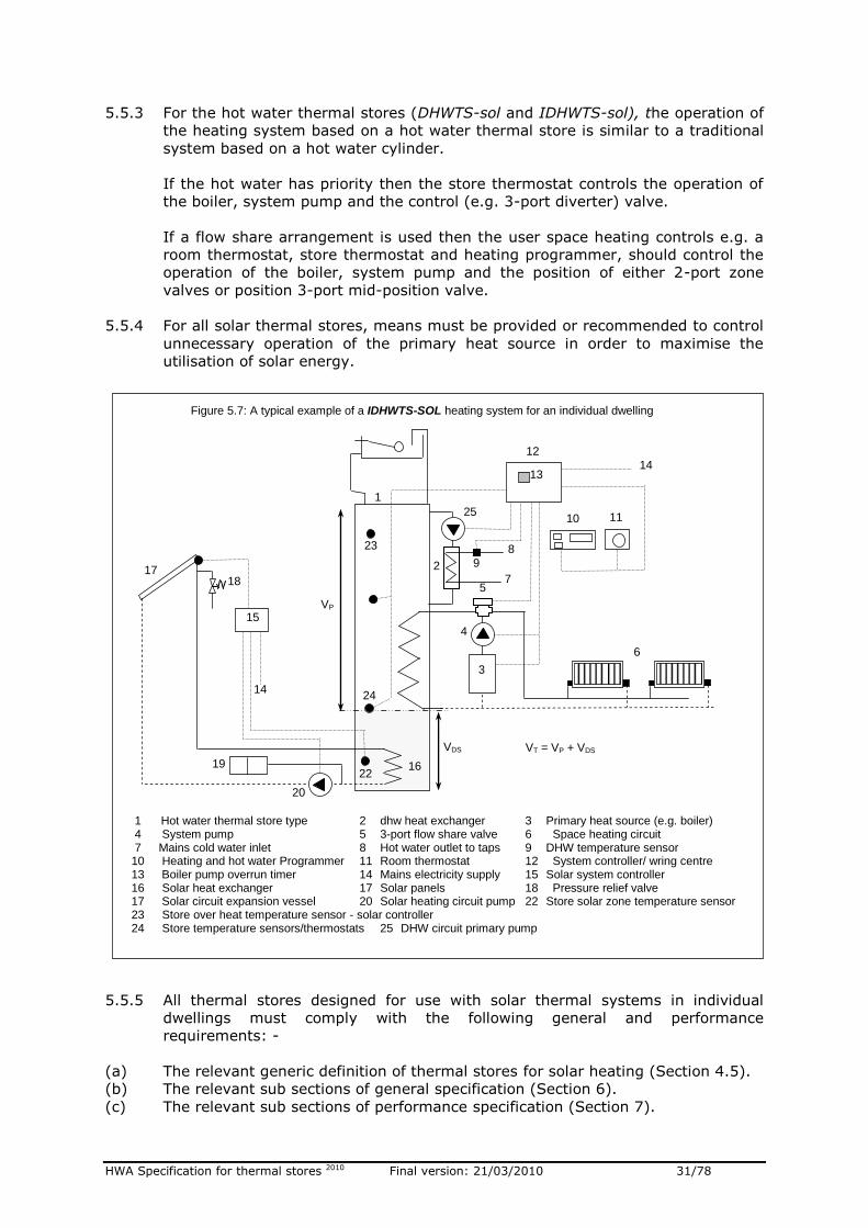
5.5.3 For the hot water thermal stores (DHWTS-sol and IDHWTS-sol), the operation of
the heating system based on a hot water thermal store is similar to a traditional
system based on a hot water cylinder.
If the hot water has priority then the store thermostat controls the operation of
the boiler, system pump and the control (e.g. 3-port diverter) valve.
If a flow share arrangement is used then the user space heating controls e.g. a
room thermostat, store thermostat and heating programmer, should control the
operation of the boiler, system pump and the position of either 2-port zone
valves or position 3-port mid-position valve.
5.5.4 For all solar thermal stores, means must be provided or recommended to control
unnecessary operation of the primary heat source in order to maximise the
utilisation of solar energy.
5.5.5 All thermal stores designed for use with solar thermal systems in individual
dwellings must comply with the following general and performance
requirements: -
(a) The relevant generic definition of thermal stores for solar heating (Section 4.5).
(b) The relevant sub sections of general specification (Section 6).
(c) The relevant sub sections of performance specification (Section 7).
VP
1
VDS
23
1 Hot water thermal store type 2 dhw heat exchanger 3 Primary heat source (e.g. boiler) 4 System pump 5 3-port flow share valve 6 Space heating circuit 7 Mains cold water inlet 8 Hot water outlet to taps 9 DHW temperature sensor 10 Heating and hot water Programmer 11 Room thermostat 12 System controller/ wring centre 13 Boiler pump overrun timer 14 Mains electricity supply 15 Solar system controller 16 Solar heat exchanger 17 Solar panels 18 Pressure relief valve 17 Solar circuit expansion vessel 20 Solar heating circuit pump 22 Store solar zone temperature sensor 23 Store over heat temperature sensor - solar controller 24 Store temperature sensors/thermostats 25 DHW circuit primary pump
Figure 5.7: A typical example of a IDHWTS-SOL heating system for an individual dwelling
6
10 11
12
14
VT = VP + VDS
14
15
16
17 18
19
20
2 7
8
25
9
13
3
4
5
22
24
HWA Specification for thermal stores 2010 Final version: 21/03/2010 32/78
5.6 HEAT PUMP THERMAL STORES FOR INDIVIDUAL DWELLINGS
The flow temperature from heat pumps range from about 55oC to about 65oC and the
domestic hot water in a thermal store is heated instantaneously by means of a heat
exchanger. Therefore to maximise the in use COP of a heat pump, only direct thermal
stores (DHWTS-hp and DITS-hp) should be used with both ground and air source heat
pumps.
A typical heat pump heating system configurations based on a direct hot water thermal
store (DHWTS-hp) and a direct integrated thermal store (DITS-HP) are shown in figures
5.9 and 5.10 respectively.
The direct hot water or integrated thermal stores (DITS-HP and DHWTS-HP) designed for
use with heat pumps should comply with the following requirements: -
5.6.1 All heat pump thermal stores should either be supplied with all the components
fitted and wired or full wiring details and a list of recommended components
(e.g. pumps, valves and controls) must be provided. The outline specification of
common components is contained in section 8 of this document.
5.6.2 For the direct integrated heat pump thermal stores (DITS-HP): -
3
4
6
9
8
VSH
1
2
VDS
21
15
VR
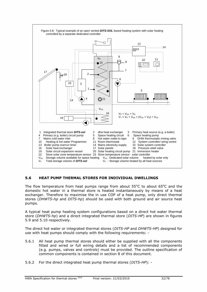
1 Integrated thermal store DITS-sol 2 dhw heat exchanger 3 Primary heat source (e.g. a boiler) 4 Primary (e.g. boiler) circuit pump 5 Space heating circuit 6 Space heating pump 7 Mains cold water inlet 8 Hot water outlet to taps 9 DHW thermostatic mixing valve 10 Heating & hot water Programmer 11 Room thermostat 12 System controller/ wring centre 13 Boiler pump overrun timer 14 Mains electricity supply 15 Solar system controller 16 Solar heat exchanger 17 Solar panels 18 Pressure relief valve 19 Solar circuit expansion vessel 20 Solar heating circuit pump 21 Immersion heater 22 Store solar zone temperature sensor 23 Store temperature sensor - solar controller VSH Storage volume available for space heating VDS : Dedicated solar volume heated by solar only
VT Total storage volume of DITS-sol VP : Storage volume heated by all heat sources
Figure 5.8: Typical example of an open vented DITS-SOL based heating system with solar heating controlled by a separate dedicated controller
5
6
10 11
13
12
14
7
VP = VSH + VR
VT = VP + VDS = (VSH + VR) + VDS
14
15
16
17 18
19
HWA Specification for thermal stores 2010 Final version: 21/03/2010 33/78
(a) One or more store thermostats or sensors in conjunction with the programmer
should control the operation of the heat pump and the primary circuit pump.
(b) The user space heating controls e.g. room thermostat and a central heating
programme should control the operation of the central heating pump and not the
operation of the heat pump.
Note: The control of both space heating and boiler circuits can be achieved using a conventional 2-channel programmer/controller, but care must be taken to ensure that the boiler is available when only space heating demand is active.
(c) The heating of a thermal store for producing dhw should have the priority over
the heating of a thermal store for space heating.
5.6.3 For the direct hot water thermal stores (DHWTS-hp), the system and controls
should be designed to give priority to heating of a thermal store for producing
hot water.
5.6.4 If it is necessary to boost the temperature of the water in a thermal store to
satisfy the dhw requirements, then, the following control logic is recommended
to minimise the use of direct electricity for heating: -
(a) The boost heater should only be switched ON, after the heat pump has
completed the store heating cycle.
(b) The boost heater should only heat the minimum storage volume necessary to
satisfy the dhw requirements.
(c) It may not be necessary to use the boost heater after each store heating cycle
during a 24h period.
(d) The means must be provided or recommended to achieve the above control
logic.
(e) There must be some means of overriding the automatic operation settings if the
user wants to manually boost the store temperature. This should be done
through the runback timer.
5.6.5 The thermal stores designed for use with heat pumps should comply with the
following general and performance requirements: -
(a) For the type DITS-HP, the relevant generic definition of integrated thermal stores
(Section 4.2).
(b) For the type DHWTS-HP, the relevant generic definition of hot water thermal
stores (Section 4.3).
(c) For types DITS-HP and DHWTS-HP, the relevant sub sections of the general
specification (Section 6).
(d) For types DITS-HP and DHWTS-HP, the relevant sub sections of the performance
specification (Section 7).

HWA Specification for thermal stores 2010 Final version: 21/03/2010 34/78
Figure 5.9 : Typical configuration of an unvented DHWTS-HP and a heat pump for a heating system in an individual dwelling.
11 12
18
19
13
9
10
2
1 14
6
16
1 Heat pump 2 Primary pump 3 PRV 4 Expansion vessel 5 Zone valve 6 Boost immersion heater 7 DHWTS-hp 8 P & T valve 9 CW inlet
10 DHW outlet 11 Programmer 12 Room thermostat 13 DHW blending valve 14 Store thermostats/sensors 15 OHT 16 Air vent 17 DHW heat exchanger 18 Control system/wiring centre 19 Power supply – control 20 Power supply – heat pump
3
4
5
5
7 8
14
15 17
3
Figure 5.10 : Typical configuration of an vented DITS-HP and a heat pump for a heating system in an individual dwelling.
11 12
18
19
13
9
10
1 14
6
1 Heat pump 2 Primary pump 3 F & E cistern 4 CH pump 6 Boost immersion heater 7 DHWTS-hp 9 CW inlet 10 DHW outlet 11 Programmer 12 Room thermostat 13 dhw blending valve 14 Store thermostats/sensors 15 OHT 16 Air vent 17 DHW heat exchanger 18 Control system/wiring centre 19 Power supply – control 20 Power supply – heat pump
7
14
17
20
2
HWA Specification for thermal stores 2010 Final version: 21/03/2010 35/78
5.7 THERMAL STORES FOR USE WITH SOLID FUEL BOILERS (e.g. wood
burners)
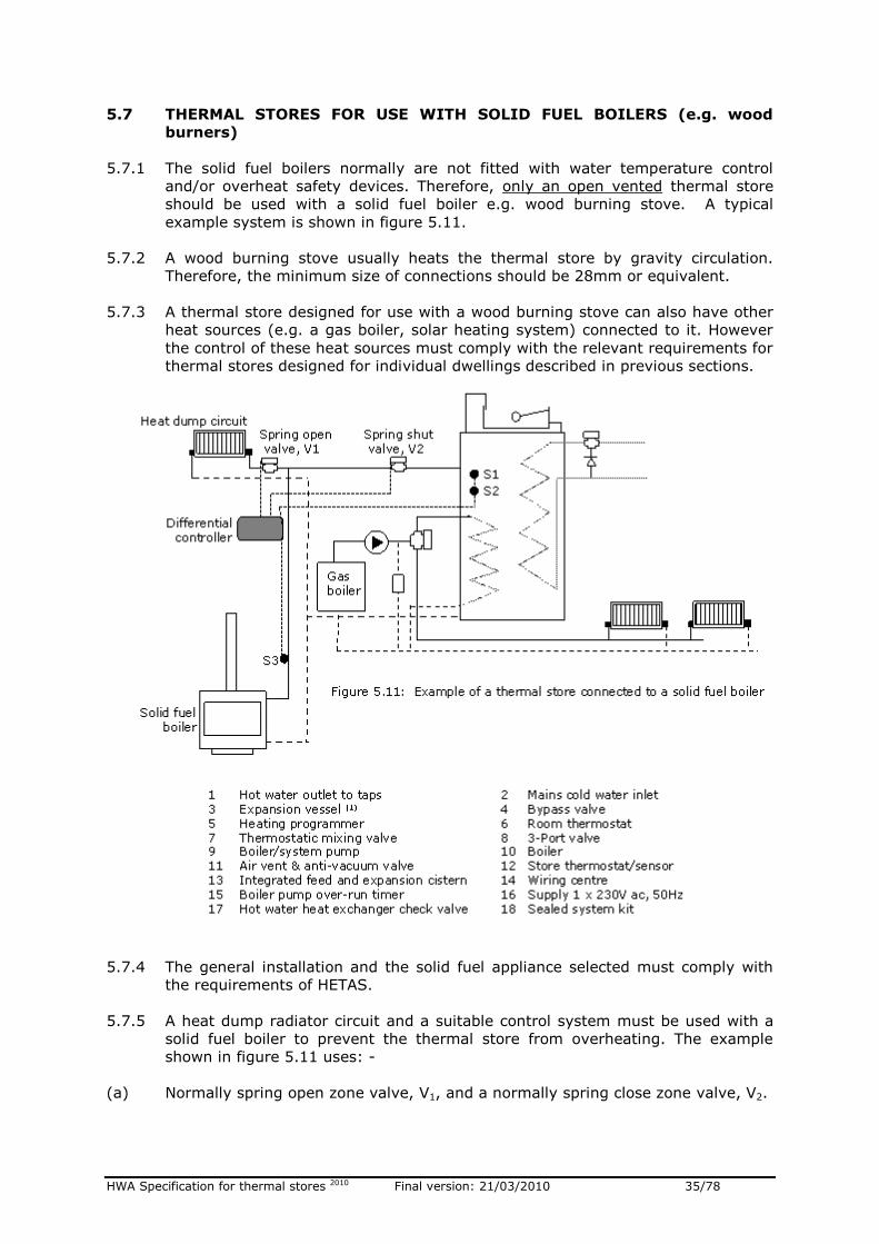
5.7.1 The solid fuel boilers normally are not fitted with water temperature control
and/or overheat safety devices. Therefore, only an open vented thermal store
should be used with a solid fuel boiler e.g. wood burning stove. A typical
example system is shown in figure 5.11.
5.7.2 A wood burning stove usually heats the thermal store by gravity circulation.
Therefore, the minimum size of connections should be 28mm or equivalent.
5.7.3 A thermal store designed for use with a wood burning stove can also have other
heat sources (e.g. a gas boiler, solar heating system) connected to it. However
the control of these heat sources must comply with the relevant requirements for
thermal stores designed for individual dwellings described in previous sections.
5.7.4 The general installation and the solid fuel appliance selected must comply with
the requirements of HETAS.
5.7.5 A heat dump radiator circuit and a suitable control system must be used with a
solid fuel boiler to prevent the thermal store from overheating. The example
shown in figure 5.11 uses: -
(a) Normally spring open zone valve, V1, and a normally spring close zone valve, V2.
HWA Specification for thermal stores 2010 Final version: 21/03/2010 36/78
(b) A store control thermostat, S1, high limit store thermostat, S2, and a pipe
thermostat, S3, mounted on the flow pipe connecting the wood burning stove to
the thermal store.
(c) A differential controller
(d) The control wiring is arranged to provide the following control logic: -
If the temperature differential ‘S3-S1’ is greater than the set point and the
store temperature, S1, is less than the set point then the differential
controller will open the zone valve V1 and close the zone valve, V2, to allow
the store to be heated by the wood burning stove.
If either the store temperature, S1, is greater than the set point or if the
overheat condition is detected by the overheat sensor, S2, then the
differential controller will not allow the store to be heated and the heat will be
diverted to the heat dump circuit.
HWA Specification for thermal stores 2010 Final version: 21/03/2010 37/78
6. GENERAL SPECIFICATION
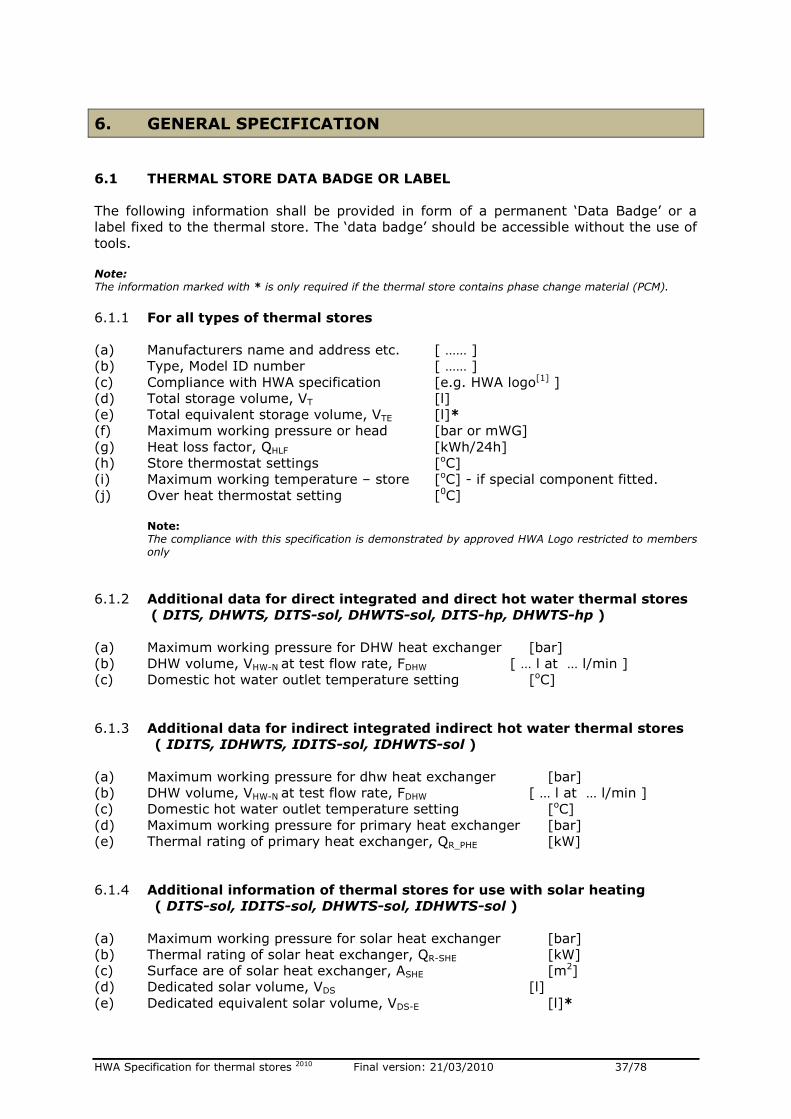
6.1 THERMAL STORE DATA BADGE OR LABEL
The following information shall be provided in form of a permanent ‘Data Badge’ or a
label fixed to the thermal store. The ‘data badge’ should be accessible without the use of
tools.
Note: The information marked with * is only required if the thermal store contains phase change material (PCM).
6.1.1 For all types of thermal stores
(a) Manufacturers name and address etc. [ …… ]
(b) Type, Model ID number [ …… ]
(c) Compliance with HWA specification [e.g. HWA logo[1] ]
(d) Total storage volume, VT [l]
(e) Total equivalent storage volume, VTE [l]*
(f) Maximum working pressure or head [bar or mWG]
(g) Heat loss factor, QHLF [kWh/24h]
(h) Store thermostat settings [oC]
(i) Maximum working temperature – store [oC] - if special component fitted.
(j) Over heat thermostat setting [0C]
Note: The compliance with this specification is demonstrated by approved HWA Logo restricted to members only
6.1.2 Additional data for direct integrated and direct hot water thermal stores
( DITS, DHWTS, DITS-sol, DHWTS-sol, DITS-hp, DHWTS-hp )
(a) Maximum working pressure for DHW heat exchanger [bar]
(b) DHW volume, VHW-N at test flow rate, FDHW [ … l at … l/min ]
(c) Domestic hot water outlet temperature setting [oC]
6.1.3 Additional data for indirect integrated indirect hot water thermal stores
( IDITS, IDHWTS, IDITS-sol, IDHWTS-sol )
(a) Maximum working pressure for dhw heat exchanger [bar]
(b) DHW volume, VHW-N at test flow rate, FDHW [ … l at … l/min ]
(c) Domestic hot water outlet temperature setting [oC]
(d) Maximum working pressure for primary heat exchanger [bar]
(e) Thermal rating of primary heat exchanger, QR_PHE [kW]
6.1.4 Additional information of thermal stores for use with solar heating
( DITS-sol, IDITS-sol, DHWTS-sol, IDHWTS-sol )
(a) Maximum working pressure for solar heat exchanger [bar]
(b) Thermal rating of solar heat exchanger, QR-SHE [kW]
(c) Surface are of solar heat exchanger, ASHE [m2]
(d) Dedicated solar volume, VDS [l]
(e) Dedicated equivalent solar volume, VDS-E [l]*
HWA Specification for thermal stores 2010 Final version: 21/03/2010 38/78
6.1.5 Additional information for unvented thermal stores
(a) Pressure relief valve (PRV) setting [ bar ]
(b) Pressure and temperature relief valve (P&T) setting [ bar / oC ]
(c) Overheat thermostat setting [ oC ]
(d) Expansion vessel size [ l ]
(e) Expansion vessel charge pressure [ bar ]
6.2 THERMAL STORE SYSTEM DESIGN AND INSTALLATION MANUAL
The system design and installation manuals should be provided with all thermal stores
and these should include, where appropriate, the following information:-
6.2.1 Installation and service instructions with examples.
6.2.2 Recommended space heating system designs and controls.
6.2.3 Recommended hot and cold water distribution networks in a dwelling (e.g. supply
to shower and pipe sizes).
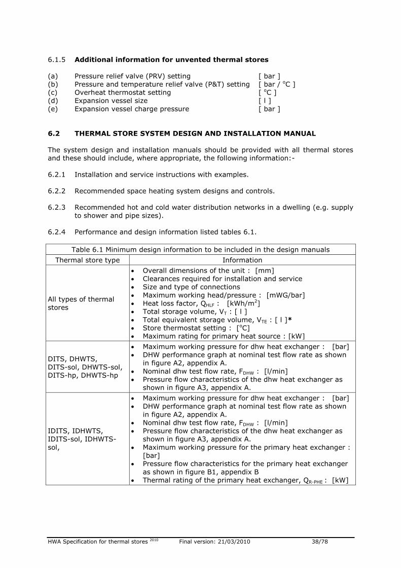
6.2.4 Performance and design information listed tables 6.1.
Table 6.1 Minimum design information to be included in the design manuals
Thermal store type Information
All types of thermal
stores
Overall dimensions of the unit : [mm]
Clearances required for installation and service
Size and type of connections
Maximum working head/pressure : [mWG/bar]
Heat loss factor, QHLF : [kWh/m2]
Total storage volume, VT : [ l ]
Total equivalent storage volume, VTE : [ l ]*
Store thermostat setting : [oC]
Maximum rating for primary heat source : [kW]
DITS, DHWTS,
DITS-sol, DHWTS-sol,
DITS-hp, DHWTS-hp
Maximum working pressure for dhw heat exchanger : [bar]
DHW performance graph at nominal test flow rate as shown
in figure A2, appendix A.
Nominal dhw test flow rate, FDHW : [l/min]
Pressure flow characteristics of the dhw heat exchanger as
shown in figure A3, appendix A.
IDITS, IDHWTS,
IDITS-sol, IDHWTS-
sol,
Maximum working pressure for dhw heat exchanger : [bar]
DHW performance graph at nominal test flow rate as shown
in figure A2, appendix A.
Nominal dhw test flow rate, FDHW : [l/min]
Pressure flow characteristics of the dhw heat exchanger as
shown in figure A3, appendix A.
Maximum working pressure for the primary heat exchanger :
[bar]
Pressure flow characteristics for the primary heat exchanger
as shown in figure B1, appendix B
Thermal rating of the primary heat exchanger, QR-PHE : [kW]
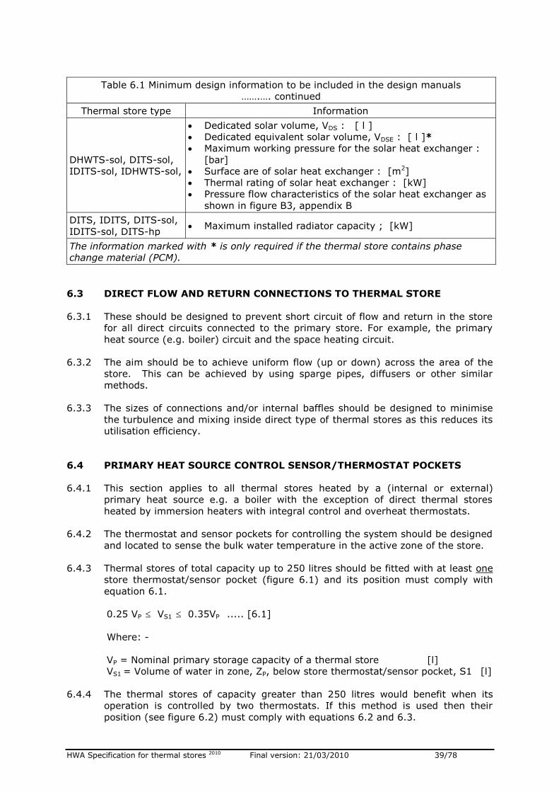
HWA Specification for thermal stores 2010 Final version: 21/03/2010 39/78
Table 6.1 Minimum design information to be included in the design manuals
…….…. continued
Thermal store type Information
DHWTS-sol, DITS-sol,
IDITS-sol, IDHWTS-sol,
Dedicated solar volume, VDS : [ l ]
Dedicated equivalent solar volume, VDSE : [ l ]*
Maximum working pressure for the solar heat exchanger :
[bar]
Surface are of solar heat exchanger : [m2]
Thermal rating of solar heat exchanger : [kW]
Pressure flow characteristics of the solar heat exchanger as
shown in figure B3, appendix B
DITS, IDITS, DITS-sol,
IDITS-sol, DITS-hp Maximum installed radiator capacity ; [kW]
The information marked with * is only required if the thermal store contains phase
change material (PCM).
6.3 DIRECT FLOW AND RETURN CONNECTIONS TO THERMAL STORE
6.3.1 These should be designed to prevent short circuit of flow and return in the store
for all direct circuits connected to the primary store. For example, the primary
heat source (e.g. boiler) circuit and the space heating circuit.
6.3.2 The aim should be to achieve uniform flow (up or down) across the area of the
store. This can be achieved by using sparge pipes, diffusers or other similar
methods.
6.3.3 The sizes of connections and/or internal baffles should be designed to minimise
the turbulence and mixing inside direct type of thermal stores as this reduces its
utilisation efficiency.
6.4 PRIMARY HEAT SOURCE CONTROL SENSOR/THERMOSTAT POCKETS
6.4.1 This section applies to all thermal stores heated by a (internal or external)
primary heat source e.g. a boiler with the exception of direct thermal stores
heated by immersion heaters with integral control and overheat thermostats.
6.4.2 The thermostat and sensor pockets for controlling the system should be designed
and located to sense the bulk water temperature in the active zone of the store.
6.4.3 Thermal stores of total capacity up to 250 litres should be fitted with at least one
store thermostat/sensor pocket (figure 6.1) and its position must comply with
equation 6.1.
0.25 VP VS1 0.35VP ..... [6.1]
Where: -
VP = Nominal primary storage capacity of a thermal store [l]
VS1 = Volume of water in zone, ZP, below store thermostat/sensor pocket, S1 [l]
6.4.4 The thermal stores of capacity greater than 250 litres would benefit when its
operation is controlled by two thermostats. If this method is used then their
position (see figure 6.2) must comply with equations 6.2 and 6.3.
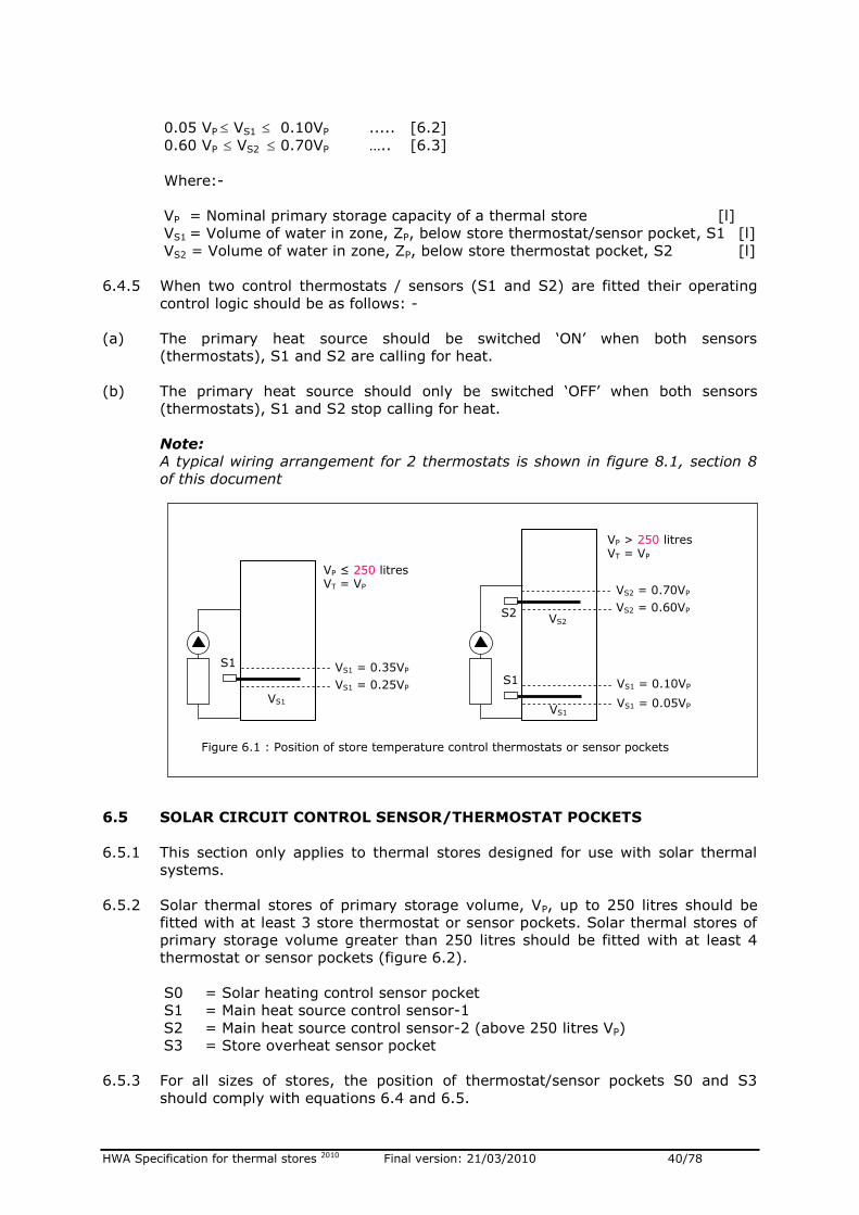
HWA Specification for thermal stores 2010 Final version: 21/03/2010 40/78
0.05 VP VS1 0.10VP ..... [6.2]
0.60 VP VS2 0.70VP ….. [6.3]
Where:-
VP = Nominal primary storage capacity of a thermal store [l]
VS1 = Volume of water in zone, ZP, below store thermostat/sensor pocket, S1 [l]
VS2 = Volume of water in zone, ZP, below store thermostat pocket, S2 [l]
6.4.5 When two control thermostats / sensors (S1 and S2) are fitted their operating
control logic should be as follows: -
(a) The primary heat source should be switched ‘ON’ when both sensors
(thermostats), S1 and S2 are calling for heat.
(b) The primary heat source should only be switched ‘OFF’ when both sensors
(thermostats), S1 and S2 stop calling for heat.
Note:
A typical wiring arrangement for 2 thermostats is shown in figure 8.1, section 8
of this document
6.5 SOLAR CIRCUIT CONTROL SENSOR/THERMOSTAT POCKETS
6.5.1 This section only applies to thermal stores designed for use with solar thermal
systems.
6.5.2 Solar thermal stores of primary storage volume, VP, up to 250 litres should be
fitted with at least 3 store thermostat or sensor pockets. Solar thermal stores of
primary storage volume greater than 250 litres should be fitted with at least 4
thermostat or sensor pockets (figure 6.2).
S0 = Solar heating control sensor pocket
S1 = Main heat source control sensor-1
S2 = Main heat source control sensor-2 (above 250 litres VP)
S3 = Store overheat sensor pocket
6.5.3 For all sizes of stores, the position of thermostat/sensor pockets S0 and S3
should comply with equations 6.4 and 6.5.
Figure 6.1 : Position of store temperature control thermostats or sensor pockets
VS1
VP ≤ 250 litres VT = VP
VS1 = 0.25VP
VS1 = 0.35VP S1
VS1 VS1 = 0.05VP
VS1 = 0.10VP
VS2
VS2 = 0.60VP
VS2 = 0.70VP
S2
VP > 250 litres VT = VP
S1
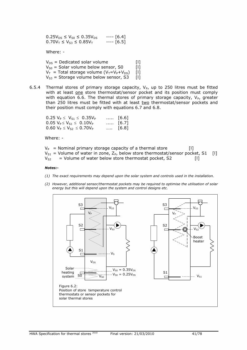
HWA Specification for thermal stores 2010 Final version: 21/03/2010 41/78
0.25VDS ≤ VS0 ≤ 0.35VDS ---- [6.4]
0.70VT ≤ VS3 ≤ 0.85VT ---- [6.5]
Where: -
VDS = Dedicated solar volume [l]
VS0 = Solar volume below sensor, S0 [l]
VT = Total storage volume (VT=VP+VDS) [l]
VS3 = Storage volume below sensor, S3 [l]
6.5.4 Thermal stores of primary storage capacity, VP, up to 250 litres must be fitted
with at least one store thermostat/sensor pocket and its position must comply
with equation 6.6. The thermal stores of primary storage capacity, VP, greater
than 250 litres must be fitted with at least two thermostat/sensor pockets and
their position must comply with equations 6.7 and 6.8.
0.25 VP VS1 0.35VP ..... [6.6]
0.05 VP VS1 0.10VP ..... [6.7]
0.60 VP VS2 0.70VP ….. [6.8]
Where: -
VP = Nominal primary storage capacity of a thermal store [l]
VS1 = Volume of water in zone, ZP, below store thermostat/sensor pocket, S1 [l]
VS2 = Volume of water below store thermostat pocket, S2 [l]
Notes:-
(1) The exact requirements may depend upon the solar system and controls used in the installation.
(2) However, additional sensor/thermostat pockets may be required to optimise the utilisation of solar
energy but this will depend upon the system and control designs etc.
VDS
S0
Solar heating system VS0
VS0 = 0.25VDS
VS0 = 0.35VDS
S1
S2
S3
VP
VS
1
VS2
VS3
Figure 6.2:
Position of store temperature control thermostats or sensor pockets for solar thermal stores
VS1
S1
S2
S3
VP
Boost heater
VS2
VS3
HWA Specification for thermal stores 2010 Final version: 21/03/2010 42/78
6.6 HEAT PUMP THERMAL STORE THERMOSTAT/SENSOR POCKETS
6.6.1 This section only applies to the thermal stores designed for use with heat pumps.
6.6.2 The thermal stores designed for use with heat pumps should be fitted with at
least 3 store thermostat or sensor pockets for controlling the heat pump and
boost heater and their position should comply with equations 6.9, 6.10 and 6.11
unless specified by the heat pump manufacturer.
0.05 VP VS1 0.10VP ..... [6.9]
0.45 VP VS2 0.55VP ..... [6.10]
0.75 VP VS2 0.85VP ….. [6.11]
Where: -
VP = Nominal primary storage capacity of a thermal store (= VT) [l]
VS1 = Volume of water in zone, ZP, below store thermostat/sensor pocket, S1 [l]
VS2 = Volume of water below store thermostat/ sensor pocket, S2 [l]
VS3 = Volume of water below OH store thermostat/sensor pocket, S3 [l]
6.7 LABELLING OF CONNECTIONS
6.7.1 The thermal store should have clearly labelled connections where applicable.
6.7.2 Pictorial labelling of components is acceptable provided it is securely fixed to the
thermal store.
6.8 SIZE AND TYPE OF CONNECTIONS
6.8.1 The thermal store pipe connections should be designed to minimise the heat
losses from the thermal store.
6.8.2 The size of connections will depend upon the capacity and type of store and the
size of heat loads connected to it. For standard products, normally 22mm for
stores up to 180 litres, 28mm for stores up to 250 litres, 35mm for stores up to
500 litres will be adequate.
6.8.3 The sizes of connections and/or internal baffles should be designed to minimise
the turbulence and mixing inside direct type of thermal stores.
6.9 DESCALING OF HOT WATER HEAT EXCHANGER
A means of de-scaling the hot water heat exchanger in the field must be provided
and the procedure must be outlined in the design and installation manuals.
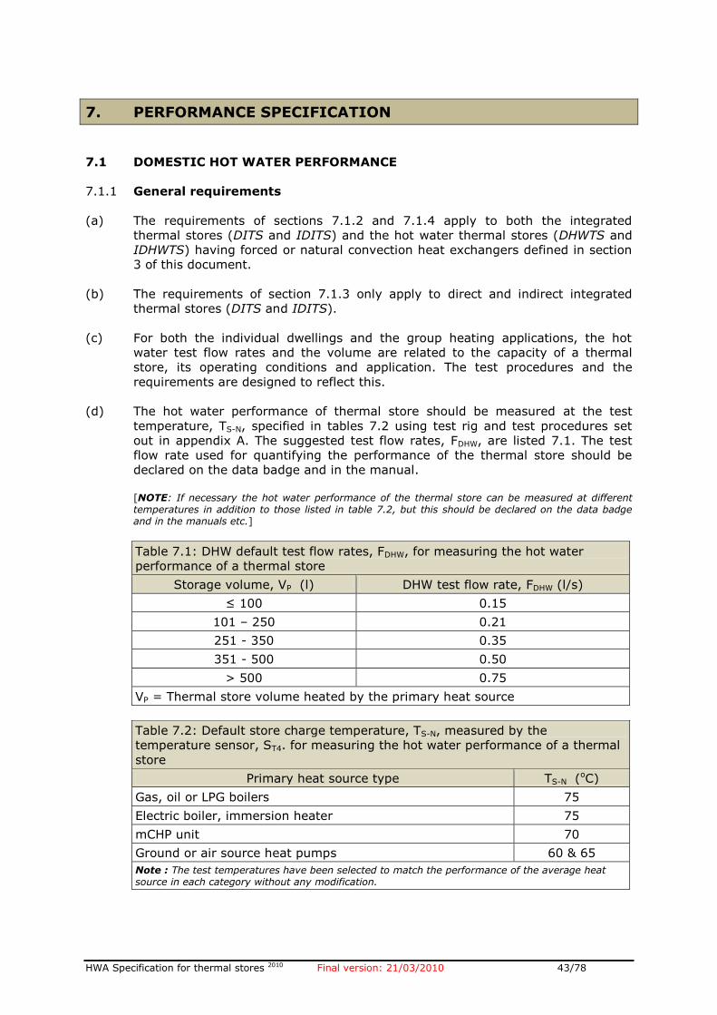
HWA Specification for thermal stores 2010 Final version: 21/03/2010 43/78
7. PERFORMANCE SPECIFICATION
7.1 DOMESTIC HOT WATER PERFORMANCE
7.1.1 General requirements
(a) The requirements of sections 7.1.2 and 7.1.4 apply to both the integrated
thermal stores (DITS and IDITS) and the hot water thermal stores (DHWTS and
IDHWTS) having forced or natural convection heat exchangers defined in section
3 of this document.
(b) The requirements of section 7.1.3 only apply to direct and indirect integrated
thermal stores (DITS and IDITS).
(c) For both the individual dwellings and the group heating applications, the hot
water test flow rates and the volume are related to the capacity of a thermal
store, its operating conditions and application. The test procedures and the
requirements are designed to reflect this.
(d) The hot water performance of thermal store should be measured at the test
temperature, TS-N, specified in tables 7.2 using test rig and test procedures set
out in appendix A. The suggested test flow rates, FDHW, are listed 7.1. The test
flow rate used for quantifying the performance of the thermal store should be
declared on the data badge and in the manual.
[NOTE: If necessary the hot water performance of the thermal store can be measured at different temperatures in addition to those listed in table 7.2, but this should be declared on the data badge and in the manuals etc.]
Table 7.1: DHW default test flow rates, FDHW, for measuring the hot water
performance of a thermal store
Storage volume, VP (l) DHW test flow rate, FDHW (l/s)
≤ 100 0.15
101 – 250 0.21
251 - 350 0.35
351 - 500 0.50
> 500 0.75
VP = Thermal store volume heated by the primary heat source
Table 7.2: Default store charge temperature, TS-N, measured by the
temperature sensor, ST4. for measuring the hot water performance of a thermal
store
Primary heat source type TS-N (oC)
Gas, oil or LPG boilers 75
Electric boiler, immersion heater 75
mCHP unit 70
Ground or air source heat pumps 60 & 65
Note : The test temperatures have been selected to match the performance of the average heat source in each category without any modification.
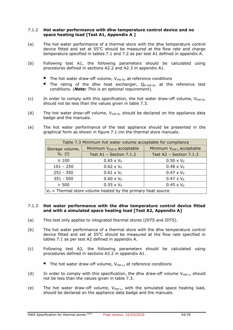
HWA Specification for thermal stores 2010 Final version: 21/03/2010 44/78
7.1.2 Hot water performance with dhw temperature control device and no
space heating load [Test A1, Appendix A ]
(a) The hot water performance of a thermal store with the dhw temperature control
device fitted and set at 55oC should be measured at the flow rate and charge
temperature specified in tables 7.1 and 7.2 as per test A1 defined in appendix A.
(b) Following test A1, the following parameters should be calculated using
procedures defined in sections A2.2 and A2.3 in appendix A1.
The hot water draw-off volume, VHW-N, at reference conditions
The rating of the dhw heat exchanger, QR-HW-N, at the reference test
conditions. (Note: This is an optional requirement).
(c) In order to comply with this specification, the hot water draw-off volume, VHW-N,
should not be less than the values given in table 7.3.
(d) The hot water draw-off volume, VHW-N, should be declared on the appliance data
badge and the manuals.
(e) The hot water performance of the test appliance should be presented in the
graphical form as shown in figure 7.1 inn the thermal store manuals.
Table 7.3 Minimum hot water volume acceptable for compliance
Storage volume,
VP (l)
Minimum VHW-N acceptable Minimum VHW-L acceptable
Test A1 – Section 7.1.2 Test A2 – Section 7.1.3
≤ 100 0.65 x VP 0.50 x VP
101 – 250 0.62 x VP 0.48 x VP
251 - 350 0.61 x VP 0.47 x VP
351 - 500 0.60 x VP 0.47 x VP
> 500 0.55 x VP 0.45 x VP
VP = Thermal store volume heated by the primary heat source
7.1.3 Hot water performance with the dhw temperature control device fitted
and with a simulated space heating load [Test A2, Appendix A]
(a) This test only applies to integrated thermal stores (DITS and IDTS).
(b) The hot water performance of a thermal store with the dhw temperature control
device fitted and set at 55oC should be measured at the flow rate specified in
tables 7.1 as per test A2 defined in appendix A.
(c) Following test A2, the following parameters should be calculated using
procedures defined in sections A3.2 in appendix A1.
The hot water draw-off volume, VHW-L, at reference conditions
(d) In order to comply with this specification, the dhw draw-off volume VHW-L, should
not be less than the values given in table 7.3.
(e) The hot water draw-off volume, VHW-L, with the simulated space heating load,
should be declared on the appliance data badge and the manuals.
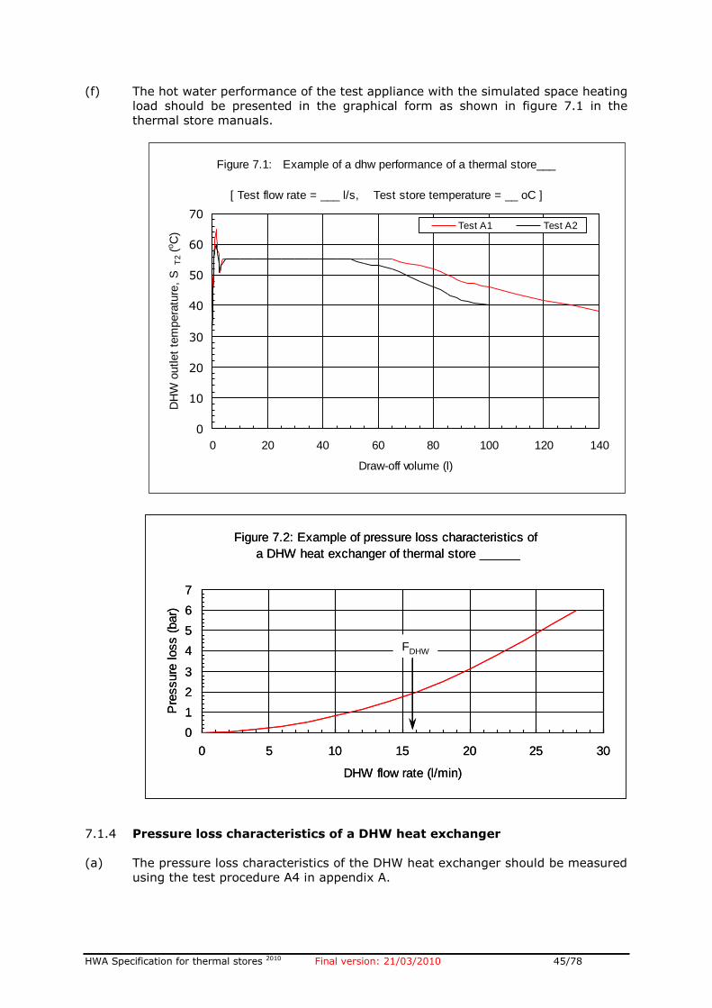
HWA Specification for thermal stores 2010 Final version: 21/03/2010 45/78
(f) The hot water performance of the test appliance with the simulated space heating
load should be presented in the graphical form as shown in figure 7.1 in the
thermal store manuals.
7.1.4 Pressure loss characteristics of a DHW heat exchanger
(a) The pressure loss characteristics of the DHW heat exchanger should be measured
using the test procedure A4 in appendix A.
Figure 7.1: Example of a dhw performance of a thermal store___
[ Test flow rate = ___ l/s, Test store temperature = __ oC ]
0
10
20
30
40
50
60
70
0 20 40 60 80 100 120 140
Draw-off volume (l)
DH
W o
utlet
tem
pera
ture
, S
T2
(oC
)
Test A1 Test A2
Figure 7.2: Example of pressure loss characteristics of
a DHW heat exchanger of thermal store ______
0
1
2
3
4
5
6
7
0 5 10 15 20 25 30
DHW flow rate (l/min)
Pre
ssure
loss (
bar)
FDHW
Figure 7.2: Example of pressure loss characteristics of
a DHW heat exchanger of thermal store ______
0
1
2
3
4
5
6
7
0 5 10 15 20 25 30
DHW flow rate (l/min)
Pre
ssure
loss (
bar)
FDHW
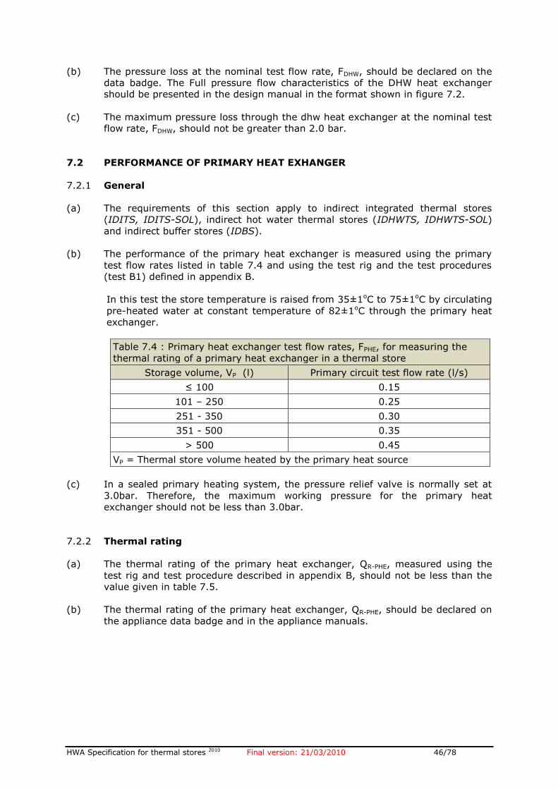
HWA Specification for thermal stores 2010 Final version: 21/03/2010 46/78
(b) The pressure loss at the nominal test flow rate, FDHW, should be declared on the
data badge. The Full pressure flow characteristics of the DHW heat exchanger
should be presented in the design manual in the format shown in figure 7.2.
(c) The maximum pressure loss through the dhw heat exchanger at the nominal test
flow rate, FDHW, should not be greater than 2.0 bar.
7.2 PERFORMANCE OF PRIMARY HEAT EXHANGER
7.2.1 General
(a) The requirements of this section apply to indirect integrated thermal stores
(IDITS, IDITS-SOL), indirect hot water thermal stores (IDHWTS, IDHWTS-SOL)
and indirect buffer stores (IDBS).
(b) The performance of the primary heat exchanger is measured using the primary
test flow rates listed in table 7.4 and using the test rig and the test procedures
(test B1) defined in appendix B.
In this test the store temperature is raised from 35±1oC to 75±1oC by circulating
pre-heated water at constant temperature of 82±1oC through the primary heat
exchanger.
Table 7.4 : Primary heat exchanger test flow rates, FPHE, for measuring the
thermal rating of a primary heat exchanger in a thermal store
Storage volume, VP (l) Primary circuit test flow rate (l/s)
≤ 100 0.15
101 – 250 0.25
251 - 350 0.30
351 - 500 0.35
> 500 0.45
VP = Thermal store volume heated by the primary heat source
(c) In a sealed primary heating system, the pressure relief valve is normally set at
3.0bar. Therefore, the maximum working pressure for the primary heat
exchanger should not be less than 3.0bar.
7.2.2 Thermal rating
(a) The thermal rating of the primary heat exchanger, QR-PHE, measured using the
test rig and test procedure described in appendix B, should not be less than the
value given in table 7.5.
(b) The thermal rating of the primary heat exchanger, QR-PHE, should be declared on
the appliance data badge and in the appliance manuals.
HWA Specification for thermal stores 2010 Final version: 21/03/2010 47/78
Table 7.5 Minimum rating of the primary heat exchanger, QR-PHE
Storage volume, VP (l) QR-PHE (kW)
≤ 100 15
101 – 200 20
201 - 300 30
302 – 400 35
401 – 500 40
> 500 45
VP = Thermal store volume heated by the primary heat source
7.2.3 Pressure loss characteristics
(a) The pressure loss characteristics of the primary heat exchanger should be
measured using the test B2 procedure in appendix B.
(b) The pressure loss at the nominal test flow rate, FPHE’ should be declared on the
data badge and the full pressure flow characteristics of the primary heat
exchanger should be presented in the design manual in the format shown in
figure 7.3.
7.3 PERFORMANCE OF SOLAR HEAT EXCHANGER
7.3.1 General
(a) The requirements of this section apply to integrated thermal stores (DITS-SOL)
and hot water solar thermal stores (DHWTS-SOL) designed for solar thermal
heating systems.
(b) The performance of the solar heat exchanger is measured using the solar circuit
test flow rates listed in table 7.6 and using the test rig and the test procedures
(test B3) defined in appendix B.
Figure 7.3 : Example of pressure loss characteristics of
a primary heat exchanger [ Model: ____ ]
0
1
2
3
4
5
6
0 4 8 12 16
Primary flow rate (l/min)
Pre
ssure
loss (
mW
G)
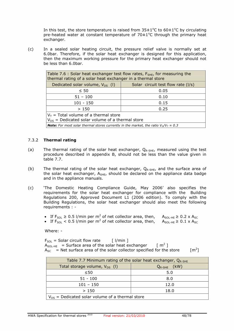
HWA Specification for thermal stores 2010 Final version: 21/03/2010 48/78
In this test, the store temperature is raised from 35±1oC to 60±1oC by circulating
pre-heated water at constant temperature of 70±1oC through the primary heat
exchanger.
(c) In a sealed solar heating circuit, the pressure relief valve is normally set at
6.0bar. Therefore, if the solar heat exchanger is designed for this application,
then the maximum working pressure for the primary heat exchanger should not
be less than 6.0bar.
Table 7.6 : Solar heat exchanger test flow rates, FSHE, for measuring the
thermal rating of a solar heat exchanger in a thermal store
Dedicated solar volume, VDS (l) Solar circuit test flow rate (l/s)
≤ 50 0.05
51 – 100 0.10
101 - 150 0.15
> 150 0.25
VT = Total volume of a thermal store
VDS = Dedicated solar volume of a thermal store
Note: For most solar thermal stores currently in the market, the ratio VD/VT ≈ 0.3
7.3.2 Thermal rating
(a) The thermal rating of the solar heat exchanger, QR-SHE, measured using the test
procedure described in appendix B, should not be less than the value given in
table 7.7.
(b) The thermal rating of the solar heat exchanger, QR-SHE, and the surface area of
the solar heat exchanger, ASHE, should be declared on the appliance data badge
and in the appliance manuals.
(c) ‘The Domestic Heating Compliance Guide, May 2006’ also specifies the
requirements for the solar heat exchanger for compliance with the Building
Regulations 200, Approved Document L1 (2006 edition). To comply with the
Building Regulations, the solar heat exchanger should also meet the following
requirements : -
If FSOL ≥ 0.5 l/min per m2 of net collector area, then, ASOL-HE ≥ 0.2 x ASC
If FSOL < 0.5 l/min per m2 of net collector area, then, ASOL-HE ≥ 0.1 x ASC
Where: -
FSOL = Solar circuit flow rate [ l/min ]
ASOL-HE = Surface area of the solar heat exchanger [ m2 ]
ASC = Net surface area of the solar collector specified for the store [m2]
Table 7.7 Minimum rating of the solar heat exchanger, QR-SHE
Total storage volume, VDS (l) QR-SHE (kW)
≤50 5.0
51 - 100 8.0
101 – 150 12.0
> 150 18.0
VDS = Dedicated solar volume of a thermal store
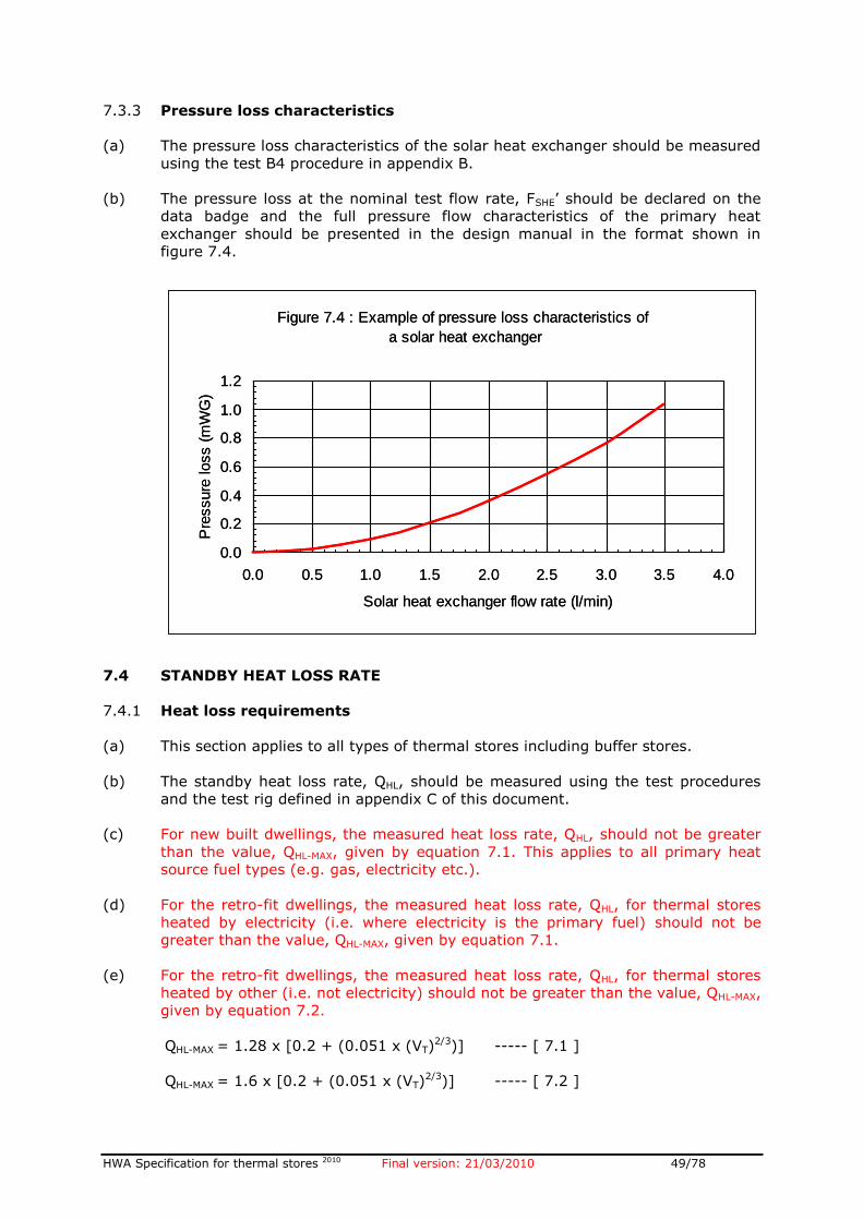
HWA Specification for thermal stores 2010 Final version: 21/03/2010 49/78
7.3.3 Pressure loss characteristics
(a) The pressure loss characteristics of the solar heat exchanger should be measured
using the test B4 procedure in appendix B.
(b) The pressure loss at the nominal test flow rate, FSHE’ should be declared on the
data badge and the full pressure flow characteristics of the primary heat
exchanger should be presented in the design manual in the format shown in
figure 7.4.
7.4 STANDBY HEAT LOSS RATE
7.4.1 Heat loss requirements
(a) This section applies to all types of thermal stores including buffer stores.
(b) The standby heat loss rate, QHL, should be measured using the test procedures
and the test rig defined in appendix C of this document.
(c) For new built dwellings, the measured heat loss rate, QHL, should not be greater
than the value, QHL-MAX, given by equation 7.1. This applies to all primary heat
source fuel types (e.g. gas, electricity etc.).
(d) For the retro-fit dwellings, the measured heat loss rate, QHL, for thermal stores
heated by electricity (i.e. where electricity is the primary fuel) should not be
greater than the value, QHL-MAX, given by equation 7.1.
(e) For the retro-fit dwellings, the measured heat loss rate, QHL, for thermal stores
heated by other (i.e. not electricity) should not be greater than the value, QHL-MAX,
given by equation 7.2.
QHL-MAX = 1.28 x [0.2 + (0.051 x (VT)2/3)] ----- [ 7.1 ]
QHL-MAX = 1.6 x [0.2 + (0.051 x (VT)2/3)] ----- [ 7.2 ]
Figure 7.4 : Example of pressure loss characteristics of
a solar heat exchanger
0.0
0.2
0.4
0.6
0.8
1.0
1.2
0.0 0.5 1.0 1.5 2.0 2.5 3.0 3.5 4.0
Solar heat exchanger flow rate (l/min)
Pre
ssure
loss (
mW
G)
Figure 7.4 : Example of pressure loss characteristics of
a solar heat exchanger
0.0
0.2
0.4
0.6
0.8
1.0
1.2
0.0 0.5 1.0 1.5 2.0 2.5 3.0 3.5 4.0
Solar heat exchanger flow rate (l/min)
Pre
ssure
loss (
mW
G)
HWA Specification for thermal stores 2010 Final version: 21/03/2010 50/78
Where: -
QHL-MAX = Maximum permitted heat loss from a thermal store, [kWh/24h]
VT = Total storage capacity of a thermal store, [ l ]
Notes:
(i) This figure should be regarded as an absolute maximum and efforts should be made to reduce it.
(ii) The actual measured value shall be declared on the data badge in the coded form and also in
the appliance manuals etc.
7.4.2 Heat loss rate for SAP calculations
The In-Use heat losses from thermal stores will be less than the measured
values (see 7.4.1. This is because:-
(a) The thermal stores are normally installed in airing cupboards like a conventional
cylinder. Therefore, the ambient temperature will be higher than 20oC specified
for the test procedures and therefore the heat losses will be lower.
(b) The thermal storage systems are now being installed with two channel
programmers for controlling both space heating and hot water. Therefore, the
thermal store is not maintained at nominal maximum temperature of 75oC.
When the boiler is not charging the thermal store, it will provide 40-50% of hot
water demands in a dwelling resulting in a significantly lower 24h mean store
temperature.
(c) The field studies have shown that the usage pattern of thermal storage heating
systems is similar to that for conventional systems.
(d) Unlike the integrated thermal stores, the hot water only thermal stores are not
maintained at high temperature when space heating is on. Therefore its 24h
average heat loss is lower than ITS.
The heat loss factors for Hot Water Only and Integrated Thermal Stores (HWTS
and ITS) for use in SAP procedures must be calculated using appropriate
equations as detailed in the separate loose sheet contained at the back of this
document.
7.5 WATER TEMPERATURE IN AN INTEGRATED FEED AND EXPANSION
CISTERN
7.5.1 This section applies to all thermal stores fitted with an integral feed and
expansion tank. The 24-hour average temperature of water in the feed and
expansion tank during the heat loss measurements (see appendix C).
7.5.2 The measured average temperature of the water in the feed and expansion tank
should not exceed 38oC.
7.5.3 The design of the feed and expansion tank, the lid and the overflow pipe
connection (e.g. dipped) should be such that the water loss due to evaporation is
minimised.
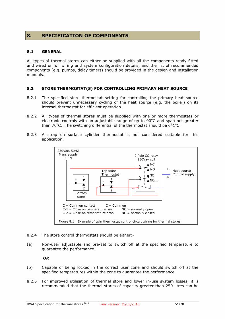
HWA Specification for thermal stores 2010 Final version: 21/03/2010 51/78
8. SPECIFICATION OF COMPONENTS
8.1 GENERAL
All types of thermal stores can either be supplied with all the components ready fitted
and wired or full wiring and system configuration details, and the list of recommended
components (e.g. pumps, delay timers) should be provided in the design and installation
manuals.
8.2 STORE THERMOSTAT(S) FOR CONTROLLING PRIMARY HEAT SOURCE
8.2.1 The specified store thermostat setting for controlling the primary heat source
should prevent unnecessary cycling of the heat source (e.g. the boiler) on its
internal thermostat for efficient operation.
8.2.2 All types of thermal stores must be supplied with one or more thermostats or
electronic controls with an adjustable range of up to 90oC and span not greater
than 70oC. The switching differential of the thermostat should be 6+1oC.
8.2.3 A strap on surface cylinder thermostat is not considered suitable for this
application.
8.2.4 The store control thermostats should be either:-
(a) Non-user adjustable and pre-set to switch off at the specified temperature to
guarantee the performance.
OR
(b) Capable of being locked in the correct user zone and should switch off at the
specified temperatures within the zone to guarantee the performance.
8.2.5 For improved utilisation of thermal store and lower in-use system losses, it is
recommended that the thermal stores of capacity greater than 250 litres can be
c
1
2
c
1
2
c
c
230Vac, 50HZ Mans supply
L N
Bottom store
thermostat
Top store Thermostat
2 Pole CO relay 230Vav coil
NC
NO
NC
NO
L
N
Heat source Control supply
C = Common contact C = Common C-1 = Close on temperature rise NO = normally open C-2 = Close on temperature drop NC = normally closed
Figure 8.1 : Example of twin thermostat control circuit wiring for thermal stores
HWA Specification for thermal stores 2010 Final version: 21/03/2010 52/78
fitted with two thermostats and wired as shown in figure 8.1 to control the
operation of heat source (e.g. a boiler) or a store charge control zone valve.
8.3 DOMESTIC HOT WATER BACK EXPANSION
8.3.1 All types of integrated thermal stores (ITS) and hot water thermal stores (HWTS)
must be supplied with a suitable expansion vessel for the domestic hot water
heat exchanger if necessary or a correct type and size should be specified in the
installation manual.
8.3.2 This expansion vessel is required to accommodate the expansion of water (due to
heating) in the heat exchanger because expansion back in to the mains may not
always be possible. (For example, a double check valve may be fitted in the
mains supply).
8.3.3 The method and equipment provided or specified for accommodating the
expansion must comply with the Model Water Bylaws and relevant standards.
8.4 HOT WATER TEMPERATURE CONTROL DEVICE
8.4.1 All types of integrated thermal stores (ITS) and hot water thermal stores (HWTS)
must be supplied with a domestic hot water outlet temperature regulating device
to prevent a hot slug reaching the hot water outlets.
8.4.2 The performance of the hot water temperature control device must meet the
requirements of section 7.1.2.
8.5 PUMP OVER-RUN CONTROL
8.5.1 If an integrated thermal store intended for an individual dwelling is used with a
boiler that requires pump over-run, then it must be supplied with a suitable
additional pump over-run delay timer or similar device.
8.5.2 The normal boiler flow temperature sensing thermostat used in majority of
boilers to control the pump over-run is not suitable for this application.
8.5.3 Integrated thermal stores for group heating applications do not require a pump
over-run delay timer.
8.6 ANTI-VACUUM AND AIR RELEASE VALVE(S)
8.6.1 Normally, direct integrated thermal stores (DITS) and direct hot water thermal
stores (DHWTS) are not recommended for group heating schemes without an
external heat exchanger. However if these are used in a group heating scheme,
then, they must have connections for fitting an air vent and anti-vacuum valves.
These items must be supplied with the store.
8.6.2 Indirect integrated and hot water thermal stores (IDITS and IDHWTS) may be
supplied without these devices.
HWA Specification for thermal stores 2010 Final version: 21/03/2010 53/78
8.7 CHARGE CONTROL VALVE
8.7.1 An integrated thermal store (DITS and IDITS) that is intended for group heating
scheme must be supplied with either a 2-port motorised zone valve or a 3-port
diverter valve controlled by the store thermostats.
8.7.2 The performance specification of this valve e.g. maximum working pressure
differential and flow rate must be included in the installation and design
instructions.
8.8 METERING SYSTEMS
8.8.1 Unless the customer specifies otherwise, a thermal store that is intended for a
group-heating scheme must either be supplied with a metering system or a
suitable system should be specified for apportioning the running costs
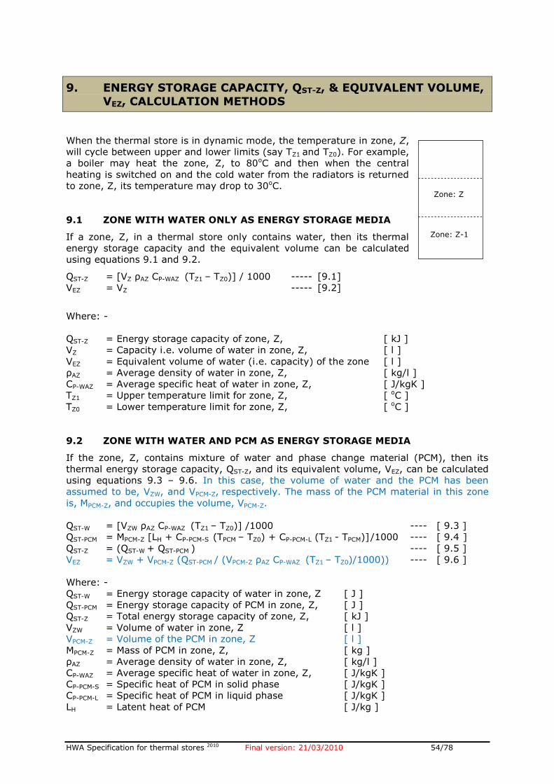
HWA Specification for thermal stores 2010 Final version: 21/03/2010 54/78
9. ENERGY STORAGE CAPACITY, QST-Z, & EQUIVALENT VOLUME,
VEZ, CALCULATION METHODS
When the thermal store is in dynamic mode, the temperature in zone, Z,
will cycle between upper and lower limits (say TZ1 and TZ0). For example,
a boiler may heat the zone, Z, to 80oC and then when the central
heating is switched on and the cold water from the radiators is returned
to zone, Z, its temperature may drop to 30oC.
9.1 ZONE WITH WATER ONLY AS ENERGY STORAGE MEDIA If a zone, Z, in a thermal store only contains water, then its thermal
energy storage capacity and the equivalent volume can be calculated
using equations 9.1 and 9.2.
QST-Z = [VZ ρAZ CP-WAZ (TZ1 – TZ0)] / 1000 ----- [9.1]
VEZ = VZ ----- [9.2]
Where: -
QST-Z = Energy storage capacity of zone, Z, [ kJ ]
VZ = Capacity i.e. volume of water in zone, Z, [ l ]
VEZ = Equivalent volume of water (i.e. capacity) of the zone [ l ]
ρAZ = Average density of water in zone, Z, [ kg/l ]
CP-WAZ = Average specific heat of water in zone, Z, [ J/kgK ]
TZ1 = Upper temperature limit for zone, Z, [ oC ]
TZ0 = Lower temperature limit for zone, Z, [ oC ]
9.2 ZONE WITH WATER AND PCM AS ENERGY STORAGE MEDIA If the zone, Z, contains mixture of water and phase change material (PCM), then its
thermal energy storage capacity, QST-Z, and its equivalent volume, VEZ, can be calculated
using equations 9.3 – 9.6. In this case, the volume of water and the PCM has been
assumed to be, VZW, and VPCM-Z, respectively. The mass of the PCM material in this zone
is, MPCM-Z, and occupies the volume, VPCM-Z.
QST-W = [VZW ρAZ CP-WAZ (TZ1 – TZ0)] /1000 ---- [ 9.3 ]
QST-PCM = MPCM-Z [LH + CP-PCM-S (TPCM – TZ0) + CP-PCM-L (TZ1 - TPCM)] /1000 ---- [ 9.4 ]
QST-Z = (QST-W + QST-PCM ) ---- [ 9.5 ]
VEZ = VZW + VPCM-Z (QST-PCM / (VPCM-Z ρAZ CP-WAZ (TZ1 – TZ0)/1000)) ---- [ 9.6 ]
Where: -
QST-W = Energy storage capacity of water in zone, Z [ J ]
QST-PCM = Energy storage capacity of PCM in zone, Z, [ J ]
QST-Z = Total energy storage capacity of zone, Z, [ kJ ]
VZW = Volume of water in zone, Z [ l ]
VPCM-Z = Volume of the PCM in zone, Z [ l ]
MPCM-Z = Mass of PCM in zone, Z, [ kg ]
ρAZ = Average density of water in zone, Z, [ kg/l ]
CP-WAZ = Average specific heat of water in zone, Z, [ J/kgK ]
CP-PCM-S = Specific heat of PCM in solid phase [ J/kgK ]
CP-PCM-L = Specific heat of PCM in liquid phase [ J/kgK ]
LH = Latent heat of PCM [ J/kg ]
Zone: Z-1
Zone: Z
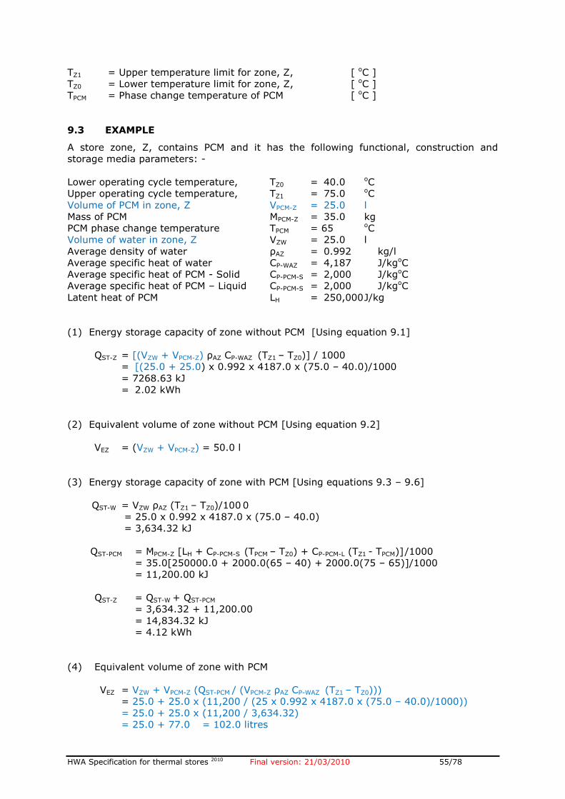
HWA Specification for thermal stores 2010 Final version: 21/03/2010 55/78
TZ1 = Upper temperature limit for zone, Z, [ oC ]
TZ0 = Lower temperature limit for zone, Z, [ oC ]
TPCM = Phase change temperature of PCM [ oC ]
9.3 EXAMPLE A store zone, Z, contains PCM and it has the following functional, construction and
storage media parameters: -
Lower operating cycle temperature, TZ0 = 40.0 oC
Upper operating cycle temperature, TZ1 = 75.0 oC
Volume of PCM in zone, Z VPCM-Z = 25.0 l
Mass of PCM MPCM-Z = 35.0 kg
PCM phase change temperature TPCM = 65 oC
Volume of water in zone, Z VZW = 25.0 l
Average density of water ρAZ = 0.992 kg/l
Average specific heat of water CP-WAZ = 4,187 J/kgoC
Average specific heat of PCM - Solid CP-PCM-S = 2,000 J/kgoC
Average specific heat of PCM – Liquid CP-PCM-S = 2,000 J/kgoC
Latent heat of PCM LH = 250,000 J/kg
(1) Energy storage capacity of zone without PCM [Using equation 9.1]
QST-Z = [(VZW + VPCM-Z) ρAZ CP-WAZ (TZ1 – TZ0)] / 1000
= [(25.0 + 25.0) x 0.992 x 4187.0 x (75.0 – 40.0)/1000
= 7268.63 kJ
= 2.02 kWh
(2) Equivalent volume of zone without PCM [Using equation 9.2]
VEZ = (VZW + VPCM-Z) = 50.0 l
(3) Energy storage capacity of zone with PCM [Using equations 9.3 – 9.6]
QST-W = VZW ρAZ (TZ1 – TZ0)/100 0
= 25.0 x 0.992 x 4187.0 x (75.0 – 40.0)
= 3,634.32 kJ
QST-PCM = MPCM-Z [LH + CP-PCM-S (TPCM – TZ0) + CP-PCM-L (TZ1 - TPCM)] /1000
= 35.0[250000.0 + 2000.0(65 – 40) + 2000.0(75 – 65)]/1000
= 11,200.00 kJ
QST-Z = QST-W + QST-PCM
= 3,634.32 + 11,200.00
= 14,834.32 kJ
= 4.12 kWh
(4) Equivalent volume of zone with PCM
VEZ = VZW + VPCM-Z (QST-PCM / (VPCM-Z ρAZ CP-WAZ (TZ1 – TZ0)))
= 25.0 + 25.0 x (11,200 / (25 x 0.992 x 4187.0 x (75.0 – 40.0)/1000))
= 25.0 + 25.0 x (11,200 / 3,634.32)
= 25.0 + 77.0 = 102.0 litres

HWA Specification for thermal stores 2010 Final version: 21/03/2010 56/78
Note:
Therefore, the effective volume of zone, Z, with PCM is equivalent to 102.0 litres of water
storage capacity i.e. the use of PCM in this example doubles storage capacity of this
zone.
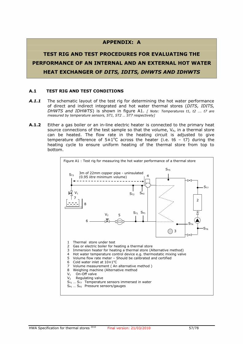
HWA Specification for thermal stores 2010 Final version: 21/03/2010 57/78
APPENDIX: A
TEST RIG AND TEST PROCEDURES FOR EVALUATING THE
PERFORMANCE OF AN INTERNAL AND AN EXTERNAL HOT WATER
HEAT EXCHANGER OF DITS, IDITS, DHWTS AND IDHWTS
A.1 TEST RIG AND TEST CONDITIONS
A.1.1 The schematic layout of the test rig for determining the hot water performance
of direct and indirect integrated and hot water thermal stores (DITS, IDITS,
DHWTS and IDHWTS) is shown in figure A1. [ Note: Temperatures t1, t2 …. t7 are
measured by temperature sensors, ST1, ST2 … ST7 respectively]
A.1.2 Either a gas boiler or an in-line electric heater is connected to the primary heat
source connections of the test sample so that the volume, VP, in a thermal store
can be heated. The flow rate in the heating circuit is adjusted to give
temperature difference of 5±1oC across the heater (i.e. t6 – t7) during the
heating cycle to ensure uniform heating of the thermal store from top to
bottom.
2
ST5
ST4
3
SP1 ST1
4
5 V2
6
8
V1
ST3 3m of 22mm copper pipe - uninsulated (0.95 litre minimum volume)
1 Thermal store under test 2 Gas or electric boiler for heating a thermal store 3 Immersion heater for heating a thermal store (Alternative method) 4 Hot water temperature control device e.g. thermostatic mixing valve 5 Volume flow rate meter – Should be calibrated and certified 6 Cold water inlet at 10±1oC 7 Volume measurement ( An alternative method ) 8 Weighing machine (Alternative method V1 On-Off valve V2 Regulating valve ST1 … ST7 Temperature sensors immersed in water SP1 … SP2 Pressure sensors/gauges
7
Figure A1 : Test rig for measuring the hot water performance of a thermal store
ST2 SP2
ST6
ST7
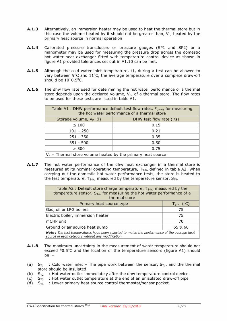
HWA Specification for thermal stores 2010 Final version: 21/03/2010 58/78
A.1.3 Alternatively, an immersion heater may be used to heat the thermal store but in
this case the volume heated by it should not be greater than, VP, heated by the
primary heat source in normal operation
A.1.4 Calibrated pressure transducers or pressure gauges (SP1 and SP2) or a
manometer may be used for measuring the pressure drop across the domestic
hot water heat exchanger fitted with temperature control device as shown in
figure A1 provided tolerances set out in A1.10 can be met.
A.1.5 Although the cold water inlet temperature, t1, during a test can be allowed to
vary between 9oC and 11oC, the average temperature over a complete draw-off
should be 10+0.5oC.
A.1.6 The dhw flow rate used for determining the hot water performance of a thermal
store depends upon the declared volume, VP, of a thermal store. The flow rates
to be used for these tests are listed in table A1.
Table A1 : DHW performance default test flow rates, FDHW, for measuring
the hot water performance of a thermal store
Storage volume, VP (l) DHW test flow rate (l/s)
≤ 100 0.15
101 – 250 0.21
251 - 350 0.35
351 - 500 0.50
> 500 0.75
VP = Thermal store volume heated by the primary heat source
A.1.7 The hot water performance of the dhw heat exchanger in a thermal store is
measured at its nominal operating temperature, TS-N, defined in table A2. When
carrying out the domestic hot water performance tests, the store is heated to
the test temperature, TS-N, measured by the temperature sensor, ST4.
Table A2 : Default store charge temperature, TS-N, measured by the
temperature sensor, ST4. for measuring the hot water performance of a
thermal store
Primary heat source type TS-N (oC)
Gas, oil or LPG boilers 75
Electric boiler, immersion heater 75
mCHP unit 70
Ground or air source heat pump 65 & 60
Note : The test temperatures have been selected to match the performance of the average heat source in each category without any modification.
A.1.8 The maximum uncertainty in the measurement of water temperature should not
exceed +0.5oC and the location of the temperature sensors (figure A1) should
be: -
(a) ST1 : Cold water inlet – The pipe work between the sensor, ST1, and the thermal
store should be insulated.
(b) ST2 : Hot water outlet immediately after the dhw temperature control device.
(c) ST3 : Hot water outlet temperature at the end of an unisulated draw-off pipe
(d) ST4 : Lower primary heat source control thermostat/sensor pocket.
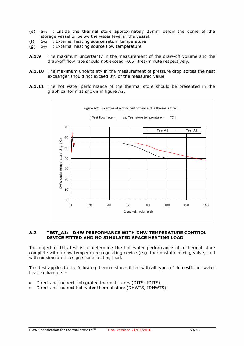
HWA Specification for thermal stores 2010 Final version: 21/03/2010 59/78
(e) ST5 : Inside the thermal store approximately 25mm below the dome of the
storage vessel or below the water level in the vessel.
(f) ST6 : External heating source return temperature
(g) ST7 : External heating source flow temperature
A.1.9 The maximum uncertainty in the measurement of the draw-off volume and the
draw-off flow rate should not exceed +0.5 litres/minute respectively.
A.1.10 The maximum uncertainty in the measurement of pressure drop across the heat
exchanger should not exceed 3% of the measured value.
A.1.11 The hot water performance of the thermal store should be presented in the
graphical form as shown in figure A2.
A.2 TEST_A1: DHW PERFORMANCE WITH DHW TEMPERATURE CONTROL
DEVICE FITTED AND NO SIMULATED SPACE HEATING LOAD
The object of this test is to determine the hot water performance of a thermal store
complete with a dhw temperature regulating device (e.g. thermostatic mixing valve) and
with no simulated design space heating load.
This test applies to the following thermal stores fitted with all types of domestic hot water
heat exchangers:-
Direct and indirect integrated thermal stores (DITS, IDITS)
Direct and indirect hot water thermal store (DHWTS, IDHWTS)
Figure A2: Example of a dhw performance of a thermal store___
[ Test f low rate = ___ l/s, Test store temperature = __ oC ]
0
10
20
30
40
50
60
70
0 20 40 60 80 100 120 140
Draw -off volume (l)
DH
W o
utle
t te
mpera
ture
, S
T2 (o
C)
Test A1 Test A2
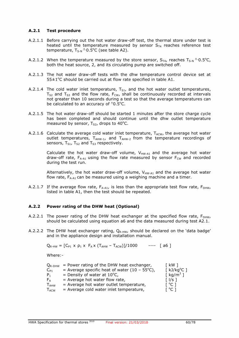
HWA Specification for thermal stores 2010 Final version: 21/03/2010 60/78
A.2.1 Test procedure
A.2.1.1 Before carrying out the hot water draw-off test, the thermal store under test is
heated until the temperature measured by sensor ST4 reaches reference test
temperature, TS-N + 0.5oC (see table A2).
A.2.1.2 When the temperature measured by the store sensor, ST4, reaches TS-N + 0.5oC,
both the heat source, 2, and its circulating pump are switched off.
A.2.1.3 The hot water draw-off tests with the dhw temperature control device set at
55±1oC should be carried out at flow rate specified in table A1.
A.2.1.4 The cold water inlet temperature, TS1, and the hot water outlet temperatures,
TS2 and TS3 and the flow rate, FCW, shall be continuously recorded at intervals
not greater than 10 seconds during a test so that the average temperatures can
be calculated to an accuracy of +0.5oC.
A.2.1.5 The hot water draw-off should be started 1 minutes after the store charge cycle
has been completed and should continue until the dhw outlet temperature
measured by sensor, TS2, drops to 40oC.
A.2.1.6 Calculate the average cold water inlet temperature, TACW, the average hot water
outlet temperatures, TAHW-1, and TAHW-2 from the temperature recordings of
sensors, TS1, TS2 and TS3 respectively.
Calculate the hot water draw-off volume, VHW-A1 and the average hot water
draw-off rate, FA-A1 using the flow rate measured by sensor FCW and recorded
during the test run.
Alternatively, the hot water draw-off volume, VHW-A1 and the average hot water
flow rate, FA-A1 can be measured using a weighing machine and a timer.
A.2.1.7 If the average flow rate, FA-A1, is less than the appropriate test flow rate, FDHW,
listed in table A1, then the test should be repeated.
A.2.2 Power rating of the DHW heat (Optional)
A.2.2.1 The power rating of the DHW heat exchanger at the specified flow rate, FDHW,
should be calculated using equation a6 and the data measured during test A2.1.
A.2.2.2 The DHW heat exchanger rating, QR-HW, should be declared on the ‘data badge’
and in the appliance design and installation manual.
QR-HW = [CP1 x ρ1 x FA x (TAHW – TACW)]/1000 ---- [ a6 ]
Where:-
QR-DHW = Power rating of the DHW heat exchanger, [ kW ]
CP1 = Average specific heat of water (10 – 55oC), [ kJ/kgoC ]
Ρ1 = Density of water at 10oC, [ kg/m3 ]
FA = Average hot water flow rate, [ l/s ]
TAHW = Average hot water outlet temperature, [ oC ]
TACW = Average cold water inlet temperature, [ oC ]
HWA Specification for thermal stores 2010 Final version: 21/03/2010 61/78
A.3 TEST A2 : DHW PERFORMANCE WITH DHW TEMPERATURE CONTROL
DEVICE AND WITH SIMULATED SPACE HEATING LOAD
A.3.1 Description
A.3.1.1 The object of this test is to determine the DHW performance of the thermal
store when the space heating is switched on and the space heating pump is
cycling on the room thermostat i.e. winter operation.
Under these conditions, the hot water in the bottom of the thermal store is
periodically replaced by the cold water from the space heating circuit (e.g.
radiators) and thus reducing the average temperature of the water in the
thermal store.
A.3.1.2 This test only applies to the Direct and Indirect integrated thermal stores (DITS
and IDITS).
A.3.1.3 The store charge temperature, TSC-A3, for this test should be calculated using
equation a7.
TSC-A3 = [TS-N (0.75VP – 45) + 50(45 + 0.25VP)] / VP ----- [ a7 ]
Where: -
TSC-A3 = Store charge temperature for test A3, [ oC ]
TS-N = Store charge temperature used for test A2 [ oC ]
VP = Store volume heated by main i.e. primary heat source, [ l ]
A.3.2 Test procedure
A.3.2.1 The test procedure is the same as for test A1 described in section A2 but before
a hot water test is started, the thermal store is charged to calculated
temperature, TSC-A3.
A.3.2.2 Before carrying out the hot water draw-off test, the thermal store under test is
heated until the temperature measured by sensor TS4 reaches TSC-A3 ± 0.5oC.
A.3.2.3 When the temperature, TS4, reaches TSC-A3 + 0.5oC, both the heat source, H1, and
the circulating pump, P1, are switched off.
A.3.2.4 The hot water draw-off tests with the dhw temperature control device set at
55±1oC should be carried out at flow rate specified in table A1.
A.3.2.5 The cold water inlet temperature, TS1, and the hot water outlet temperatures,
TS2 and TS3 and the flow rate, FCW, shall be continuously recorded at intervals
not greater than 10 seconds during a test so that the average temperatures can
be calculated to an accuracy of +0.5oC.
A.3.2.6 The hot water draw-off should be started 1 minutes after the store charge cycle
has been completed and should continue until the dhw outlet temperature
measured by sensor, TS2, drops to 40oC.
A.3.2.7 Calculate the average cold water inlet temperature, TACW, the average hot water
outlet temperatures, TAHW-1, and TAHW-2 from the temperature recordings of
sensors, TS1, TS2 and TS3 respectively.
HWA Specification for thermal stores 2010 Final version: 21/03/2010 62/78
Calculate the hot water draw-off volume, VWH-A1 and the average hot water
draw-off rate, FA-A1 using the flow rate measured by sensor FCW and recorded
during the test run.
Alternatively, the hot water draw-off volume, VWH-A3 and the average hot water
flow rate, FA-A1 can be measured using a weighing machine and a timer.
A.3.2.8 If the average flow rate, FA-A1, is less than the appropriate test flow rate, FDHW,
listed in table A1, then the test should be repeated.
A.3.2.9 The dhw draw-off volume, VHW-2, should be declared on the appliance data
badge and in the appliance design and installation manuals
A.4 TEST A3 : PRESSURE LOSS CHARACTERISTICS OF DHW HEAT
EXCHANGER
A.4.1.1 This test applies to the following thermal stores fitted with all types of domestic
hot water heat exchangers:-
Direct and indirect integrated thermal stores (DITS, IDITS)
Direct and indirect hot water thermal stores (DHWTS, IDHWTS)
A.4.1.2 The pressure loss across the hot water heat exchanger should be measured with
the inline temperature control device (e.g. thermostatic mixing valve) fitted at
set at 55oC and when the store temperature is cold i.e. with no significant
extraction of heat.
A.4.1.3 The cold water inlet temperature should be 10+0.5oC.
A.4.1.4 The pressure loss should be measured at the following flow rates. FDHW, is the
nominal domestic hot water test flow rate for the thermal store under test (see
table A1).
0.5 x FDHW
0.75 x FDHW
FDHW
1.10 x FDHW
1.25 x FDHW
A.4.1.5 The data should be presented in the design and installation manual in a
graphical form as shown in figure 7.2 in section 7. and the pressure loss at
nominal flow rate, FDHW, should be declared on a thermal store ‘data badge’.
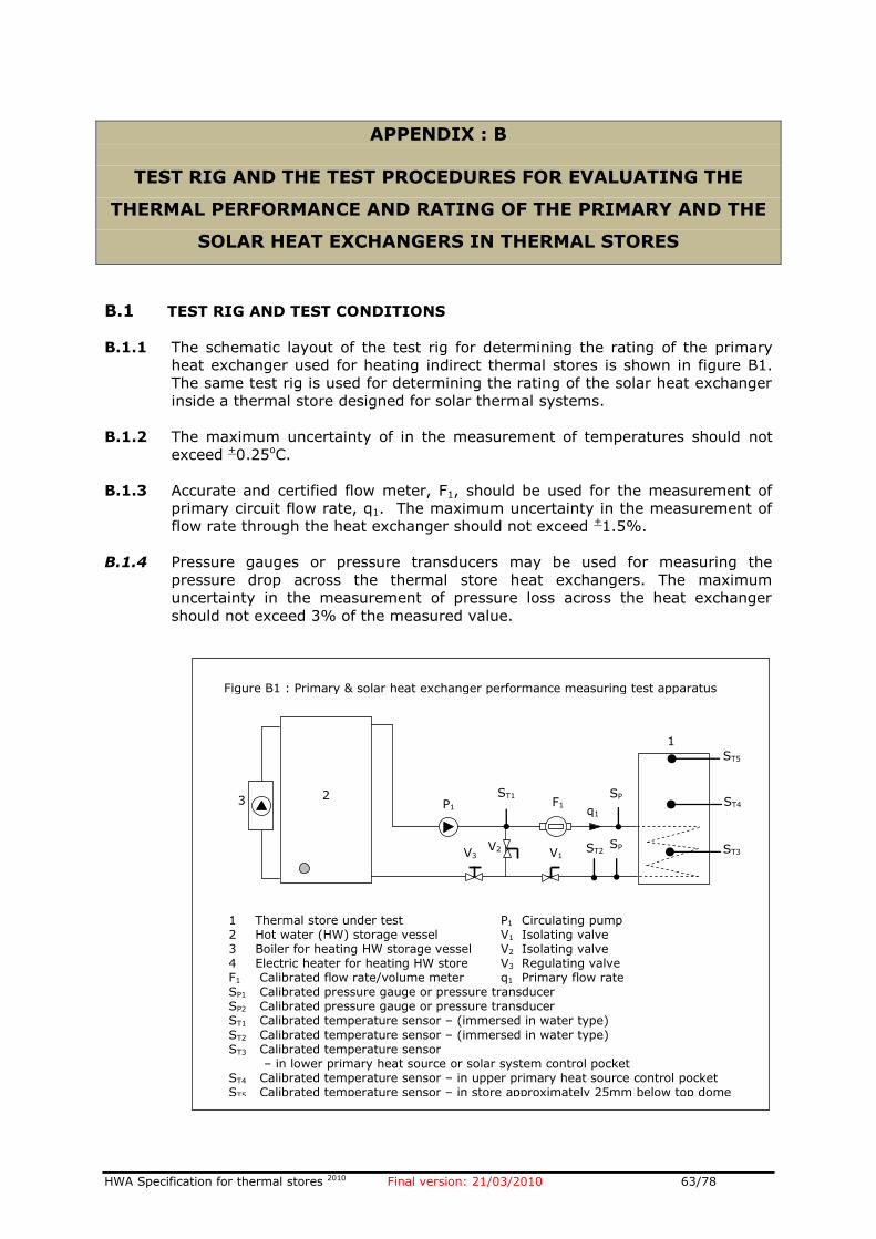
HWA Specification for thermal stores 2010 Final version: 21/03/2010 63/78
APPENDIX : B
TEST RIG AND THE TEST PROCEDURES FOR EVALUATING THE
THERMAL PERFORMANCE AND RATING OF THE PRIMARY AND THE
SOLAR HEAT EXCHANGERS IN THERMAL STORES
B.1 TEST RIG AND TEST CONDITIONS
B.1.1 The schematic layout of the test rig for determining the rating of the primary
heat exchanger used for heating indirect thermal stores is shown in figure B1.
The same test rig is used for determining the rating of the solar heat exchanger
inside a thermal store designed for solar thermal systems.
B.1.2 The maximum uncertainty of in the measurement of temperatures should not
exceed +0.25oC.
B.1.3 Accurate and certified flow meter, F1, should be used for the measurement of
primary circuit flow rate, q1. The maximum uncertainty in the measurement of
flow rate through the heat exchanger should not exceed +1.5%.
B.1.4 Pressure gauges or pressure transducers may be used for measuring the
pressure drop across the thermal store heat exchangers. The maximum
uncertainty in the measurement of pressure loss across the heat exchanger
should not exceed 3% of the measured value.
Figure B1 : Primary & solar heat exchanger performance measuring test apparatus
SP
1 F1
SP
2
ST2
ST1
ST3
ST4 2
1
V1 V2 V3
P1 q1
ST5
3
1 Thermal store under test P1 Circulating pump 2 Hot water (HW) storage vessel V1 Isolating valve 3 Boiler for heating HW storage vessel V2 Isolating valve 4 Electric heater for heating HW store V3 Regulating valve F1 Calibrated flow rate/volume meter q1 Primary flow rate SP1 Calibrated pressure gauge or pressure transducer SP2 Calibrated pressure gauge or pressure transducer ST1 Calibrated temperature sensor – (immersed in water type)
ST2 Calibrated temperature sensor – (immersed in water type) ST3 Calibrated temperature sensor – in lower primary heat source or solar system control pocket ST4 Calibrated temperature sensor – in upper primary heat source control pocket ST5 Calibrated temperature sensor – in store approximately 25mm below top dome
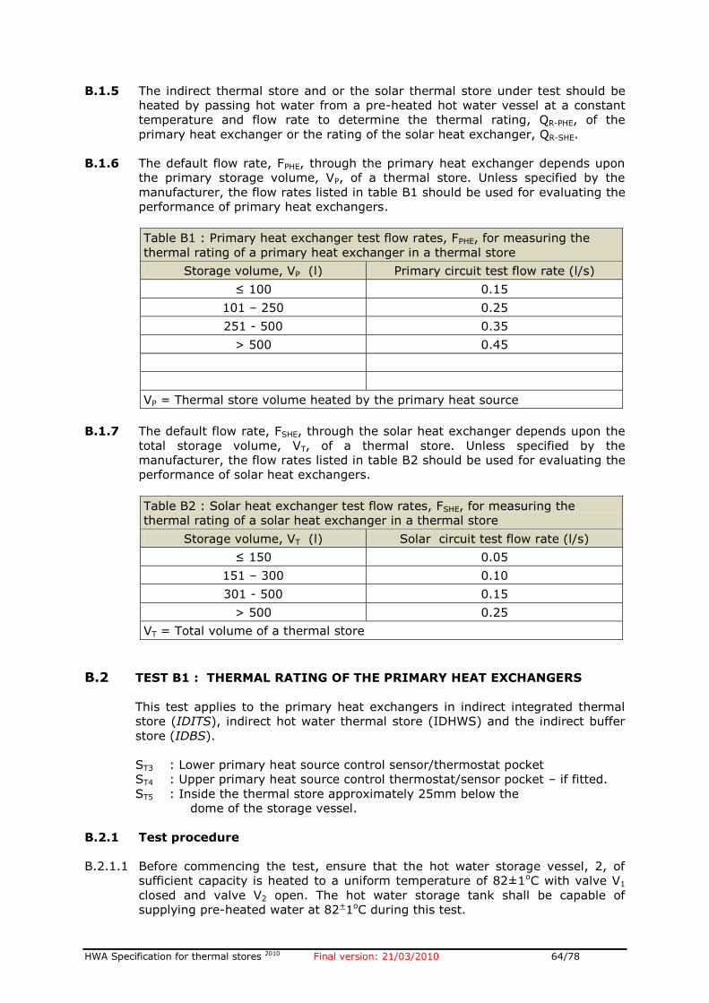
HWA Specification for thermal stores 2010 Final version: 21/03/2010 64/78
B.1.5 The indirect thermal store and or the solar thermal store under test should be
heated by passing hot water from a pre-heated hot water vessel at a constant
temperature and flow rate to determine the thermal rating, QR-PHE, of the
primary heat exchanger or the rating of the solar heat exchanger, QR-SHE.
B.1.6 The default flow rate, FPHE, through the primary heat exchanger depends upon
the primary storage volume, VP, of a thermal store. Unless specified by the
manufacturer, the flow rates listed in table B1 should be used for evaluating the
performance of primary heat exchangers.
Table B1 : Primary heat exchanger test flow rates, FPHE, for measuring the
thermal rating of a primary heat exchanger in a thermal store
Storage volume, VP (l) Primary circuit test flow rate (l/s)
≤ 100 0.15
101 – 250 0.25
251 - 500 0.35
> 500 0.45
VP = Thermal store volume heated by the primary heat source
B.1.7 The default flow rate, FSHE, through the solar heat exchanger depends upon the
total storage volume, VT, of a thermal store. Unless specified by the
manufacturer, the flow rates listed in table B2 should be used for evaluating the
performance of solar heat exchangers.
Table B2 : Solar heat exchanger test flow rates, FSHE, for measuring the
thermal rating of a solar heat exchanger in a thermal store
Storage volume, VT (l) Solar circuit test flow rate (l/s)
≤ 150 0.05
151 – 300 0.10
301 - 500 0.15
> 500 0.25
VT = Total volume of a thermal store
B.2 TEST B1 : THERMAL RATING OF THE PRIMARY HEAT EXCHANGERS
This test applies to the primary heat exchangers in indirect integrated thermal
store (IDITS), indirect hot water thermal store (IDHWS) and the indirect buffer
store (IDBS).
ST3 : Lower primary heat source control sensor/thermostat pocket
ST4 : Upper primary heat source control thermostat/sensor pocket – if fitted.
ST5 : Inside the thermal store approximately 25mm below the
dome of the storage vessel.
B.2.1 Test procedure
B.2.1.1 Before commencing the test, ensure that the hot water storage vessel, 2, of
sufficient capacity is heated to a uniform temperature of 82±1oC with valve V1
closed and valve V2 open. The hot water storage tank shall be capable of
supplying pre-heated water at 82+1oC during this test.
HWA Specification for thermal stores 2010 Final version: 21/03/2010 65/78
B.2.1.2 Also ensure that primary flow rate is adjusted to the value, FPHE specified in
table B1 by means of a regulating valve V3. This may require further adjustment
when the thermal store heating test is started.
.
B.2.1.3 Open valve, V1 and close valve V2 so that the thermal store starts to heat up. If
necessary adjust primary flow rate, q1, to value, FPHE, specified in table B1.
B.2.1.4 Set the flow rate, Q, through the primary heat exchanger to the appropriate
nominal charge flow rate, FPH, specified in table B1 in section B1.3.
B.2.1.5 When the thermal store temperature measured by sensor, ST3, reaches 35±1oC,
start reading and recording the following parameters at maximum interval of
60s.
Thermal store temperatures ST2, ST3 and ST4
Primary flow and return temperatures, ST1 and ST2
Primary circuit flow rate, q1
B.2.1.6 Continue heating the thermal store and the data logging until the store
temperature measured by sensor, ST3, reaches 75±1oC.
B.2.2 Calculations and presentation of results
B.2.2.1 The average thermal rating of the primary heat exchanger, QR-PHE, should be
calculated using equation ‘b1’ and the data collected during test B1.
B.2.2.2 The heat exchanger rating, QR-PHE, and the test flow rate, FPHE, should be
declared on the thermal store ‘data badge’ and the design manuals.
QR-PHE = Σ[Q1 x Cp1 x ρ1 x (TS1-1 – TS2-1) + Q2 x Cp2 x ρ2 x (TS1-2 – TS2-2) +
….. QN x CpN x ρN x (TS1-N– TS2-N)] / (1000 x N) ---- [ b1 ]
Where:-
QR-PHE = Thermal rating of the primary heat exchanger, [ kW ]
Qn = Primary circuit flow rate at measurement ‘n’ (n = 1…..N), [ l/s ]
Cpn = Specific heat of water at measurement ‘n’ (n = 1…N), [ kJ/kgoC ]
Ρn = Density of water at measurement ‘n’ (n = 1…N), [ kg/m3 ]
TS1-n = Primary flow temperature at measurement ‘n’ (n=1….N), [ oC ]
TS2-n = Primary return temperature at measurement ‘n’ (n=1….N), [ oC ]
N = Number of readings
B.3 TEST B2 : FLOW RESISTANCE CHARACTERISTICS OF THE PRIMARY HEAT
EXCHANGER
B.3.1 This test applies to the primary heat exchangers in indirect integrated thermal
store (IDITS), indirect hot water thermal store (IDHWS) and the indirect buffer
store (IDBS).
B.3.2 The pressure drop across the primary indirect heat exchanger should be
measured at ambient conditions i.e. when both flow and return temperatures
are at 20±5oC.
HWA Specification for thermal stores 2010 Final version: 21/03/2010 66/78
B.3.3 The pressure loss should be measured at the following flow rates. FPH, is the
nominal primary heat exchanger test flow rate (see table B1)
0.5 x FPHE
0.75 x FPHE
FPHE
1.10 x FPHE
1.25 x FPHE
B.3.4 The data should be presented in the design and installation manual in a
graphical form as shown in figure 7.3 in section 7. and the pressure loss at
nominal flow rate, FPHE, should be declared on a thermal store ‘data badge’.
B.4 TEST B3 : THERMAL RATING OF THE SOLAR HEAT EXCHANGERS
This test applies to all thermal stores (e.g. IDITS-sol, DITS-sol, DHWTS-sol,
IDHWTS-sol) which are designed to be used with solar thermal systems and are
heated indirectly by means of solar heat exchanger.
ST3 : Solar zone sensor pocket designed for controlling solar thermal system
ST4 : Lower primary heat source control thermostat/sensor pocket – if fitted.
ST5 : Inside the thermal store approximately 25mm below the
dome of the storage vessel.
B.4.1 Test procedure
B.4.1.1 Before commencing the test, ensure that the hot water storage vessel, 2, of
sufficient capacity is heated to a uniform temperature of 70±1oC with valve V1
closed and valve V2 open. The hot water storage tank shall be capable of
supplying pre-heated water at 70+1oC during this test.
B.4.1.2 Also ensure that solar heat exchanger flow rate is adjusted to the value, FSHE
specified in table B2 by means of a regulating valve V3. This may require further
adjustment when the thermal store heating test is started.
.
B.4.1.3 Open valve, V1 and close valve V2 so that the thermal store starts to heat up. If
necessary adjust primary flow rate, q1, to value, FSHE, specified in table B2.
B.4.1.4 Set the flow rate, Q, through the primary heat exchanger to the appropriate
nominal charge flow rate, FSHE, specified in table B2 in section B1.4.
B.4.1.5 When the thermal store temperature measured by sensor, ST3, reaches 35±1oC,
start reading and recording the following parameters at maximum interval of
60s.
Thermal store temperatures ST2, ST3 and ST4
Solar heat exchanger flow and return temperatures, ST1 and ST2
Solar heat exchanger circuit flow rate, q1
B.4.1.6 Continue heating the thermal store and the data logging until the store
temperature measured by sensor, TS3, reaches 60±1oC.
B.4.2 Calculations and presentation of results
HWA Specification for thermal stores 2010 Final version: 21/03/2010 67/78
B.4.2.1 The average thermal rating of the primary heat exchanger, QR-SHE, should be
calculated using equation ‘b2’ and the data collected during test B3.
B.4.2.2 The heat exchanger rating, QR-SHE, and the test flow rate, FSHE, should be
declared on the thermal store ‘data badge’ and the design manuals.
QR-SH E = Σ[Q1 x Cp1 x ρ1 x (TS1-1 – TS2-1) + Q2 x Cp2 x ρ2 x (TS1-2 – TS2-2) +
….. QN x CpN x ρN x (TS1-N– TS2-N)] / (1000 x N) ---- [ b2 ]
Where:-
QR-SHE = Thermal rating of the solar heat exchanger, [ kW ]
Qn = Solar circuit flow rate at measurement ‘n’ (n = 1…..N), [ l/s ]
Cpn = Specific heat of water at measurement ‘n’ (n = 1…N), [ kJ/kgoC ]
Ρn = Density of water at measurement ‘n’ (n = 1…N), [ kg/m3 ]
TS1-n = Solar HE flow temperature at measurement ‘n’ (n=1….N), [ oC ]
TS2-n = Solar HE return temperature at measurement ‘n’ (n=1….N),[ oC ]
N = Number of readings
B.5 TEST B4 : FLOW RESISTANCE CHARACTERISTICS OF THE SOLAR HEAT
EXCHANGER
B.5.1 This test applies to all thermal stores designed to be used with solar thermal
systems and in which the energy storage medium (e.g. primary water) is heated
indirectly by means of a heat exchanger.
B.5.2 The pressure drop across the solar heat exchanger should be measured at
ambient conditions i.e. when both flow and return temperatures are at 20±5oC.
B.5.3 The pressure loss should be measured at the following flow rates. FSOL, is the
nominal solar heat exchanger test flow rate (see table B2)
0.5 x FSOL
0.75 x FSOL
FPH
1.10 x FSOL
1.25 x FSOL
B.5.4 The data should be presented in the design and installation manual in a
graphical form as shown in figure 7.4 in section 7. and the pressure loss at
nominal flow rate, FSHE, should be declared on a thermal store ‘data badge’.
HWA Specification for thermal stores 2010 Final version: 21/03/2010 68/78
APPENDIX : C
TEST RIG AND THE TEST PROCEDURES FOR MEASURING THE
STANDBY HEAT LOSS OF A THERMAL STORE AND THE
TEMPERATURE OF THE WATER IN THE INTEGRATED FEED AND THE
EXPANSION TANK (IF FITTED).
D.1 GENERAL
D.1.1 The objectives of this test are to determine the standby heat loss from a
thermal store and the temperature of water in the integral feed and expansion
cistern (if fitted) at reference test conditions without any components fitted.
This test applies to all types of thermal stores (i.e. integrated, hot water only
and buffer stores).
D.1.2 During this test, all exposed pipe work, which is integral part of a thermal store,
should be insulated as recommended in the installation instructions supplied
with the test sample.
D.1.3 If the thermal store (e.g. ITS & HWTS) is fitted with an external hot water heat
exchanger as shown in figure C1.1 then it should be tested with this heat
exchanger and the associated components.
D.2 TEST RIG AND TEST SAMPLE
D.2.1 The standing heat loss measurement test shall be performed on a thermal store
(i.e. primary water storage vessel of types covered by this document) fitted with
a horizontally mounted immersion heater or a fixed electrical element of 3 kW
output mounted so as to heat at least the storage volume specified in table A1.
For primary stores of up to 250l total storage volume (VT), a 3kW element shall
be used. For larger primary stores (VT > 250l) an element of greater output can
be used as specified by the manufacturer.
This condition shall be checked by heating the primary store under test by
means of the immersion heater or an element until the temperature at the
measuring point (TW on figure C1) reaches 75±1oC.
The thermal store temperature, TW, is measured using the boiler control sensor
pocket (Lower pocket if a thermal store has two boiler control sensor pockets). If
suitable sensor pockets for measuring temperature, TW, is not provided on the
test sample, then these temperatures may be measured on the metal surface of
the vessel (under the insulation).
D.2.2 Apart from the introduction of the immersion heater or element in the test
sample, all other aspects of the primary store design shall be as identical as
possible to the production model, particularly with regard to the insulation
characteristics and hydraulic connections.
D.2.3 In circumstances where it is impossible to fit an immersion heater, then an
external electrical flow heater and a circulating pump can be substituted as
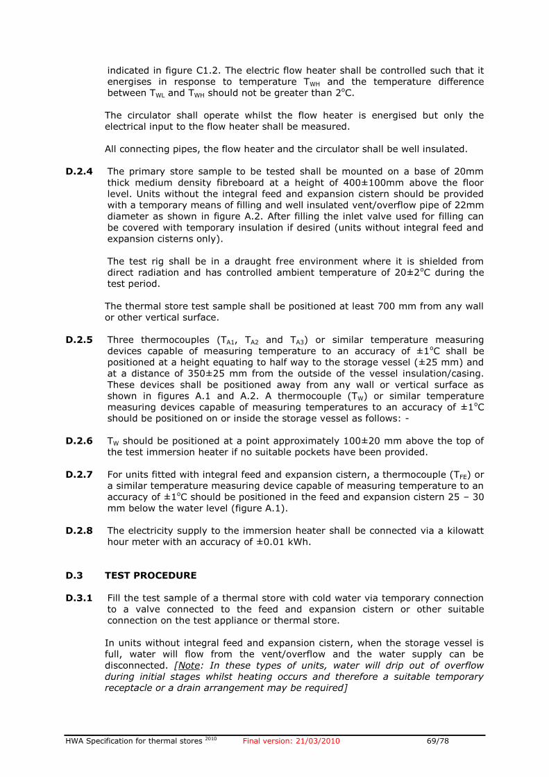
HWA Specification for thermal stores 2010 Final version: 21/03/2010 69/78
indicated in figure C1.2. The electric flow heater shall be controlled such that it
energises in response to temperature TWH and the temperature difference
between TWL and TWH should not be greater than 2oC.
The circulator shall operate whilst the flow heater is energised but only the
electrical input to the flow heater shall be measured.
All connecting pipes, the flow heater and the circulator shall be well insulated.
D.2.4 The primary store sample to be tested shall be mounted on a base of 20mm
thick medium density fibreboard at a height of 400±100mm above the floor
level. Units without the integral feed and expansion cistern should be provided
with a temporary means of filling and well insulated vent/overflow pipe of 22mm
diameter as shown in figure A.2. After filling the inlet valve used for filling can
be covered with temporary insulation if desired (units without integral feed and
expansion cisterns only).
The test rig shall be in a draught free environment where it is shielded from
direct radiation and has controlled ambient temperature of 20±2oC during the
test period.
The thermal store test sample shall be positioned at least 700 mm from any wall
or other vertical surface.
D.2.5 Three thermocouples (TA1, TA2 and TA3) or similar temperature measuring
devices capable of measuring temperature to an accuracy of ±1oC shall be
positioned at a height equating to half way to the storage vessel (±25 mm) and
at a distance of 350±25 mm from the outside of the vessel insulation/casing.
These devices shall be positioned away from any wall or vertical surface as
shown in figures A.1 and A.2. A thermocouple (TW) or similar temperature
measuring devices capable of measuring temperatures to an accuracy of ±1oC
should be positioned on or inside the storage vessel as follows: -
D.2.6 TW should be positioned at a point approximately 100±20 mm above the top of
the test immersion heater if no suitable pockets have been provided.
D.2.7 For units fitted with integral feed and expansion cistern, a thermocouple (TFE) or
a similar temperature measuring device capable of measuring temperature to an
accuracy of ±1oC should be positioned in the feed and expansion cistern 25 – 30
mm below the water level (figure A.1).
D.2.8 The electricity supply to the immersion heater shall be connected via a kilowatt
hour meter with an accuracy of ±0.01 kWh.
D.3 TEST PROCEDURE
D.3.1 Fill the test sample of a thermal store with cold water via temporary connection
to a valve connected to the feed and expansion cistern or other suitable
connection on the test appliance or thermal store.
In units without integral feed and expansion cistern, when the storage vessel is
full, water will flow from the vent/overflow and the water supply can be
disconnected. [Note: In these types of units, water will drip out of overflow
during initial stages whilst heating occurs and therefore a suitable temporary
receptacle or a drain arrangement may be required]
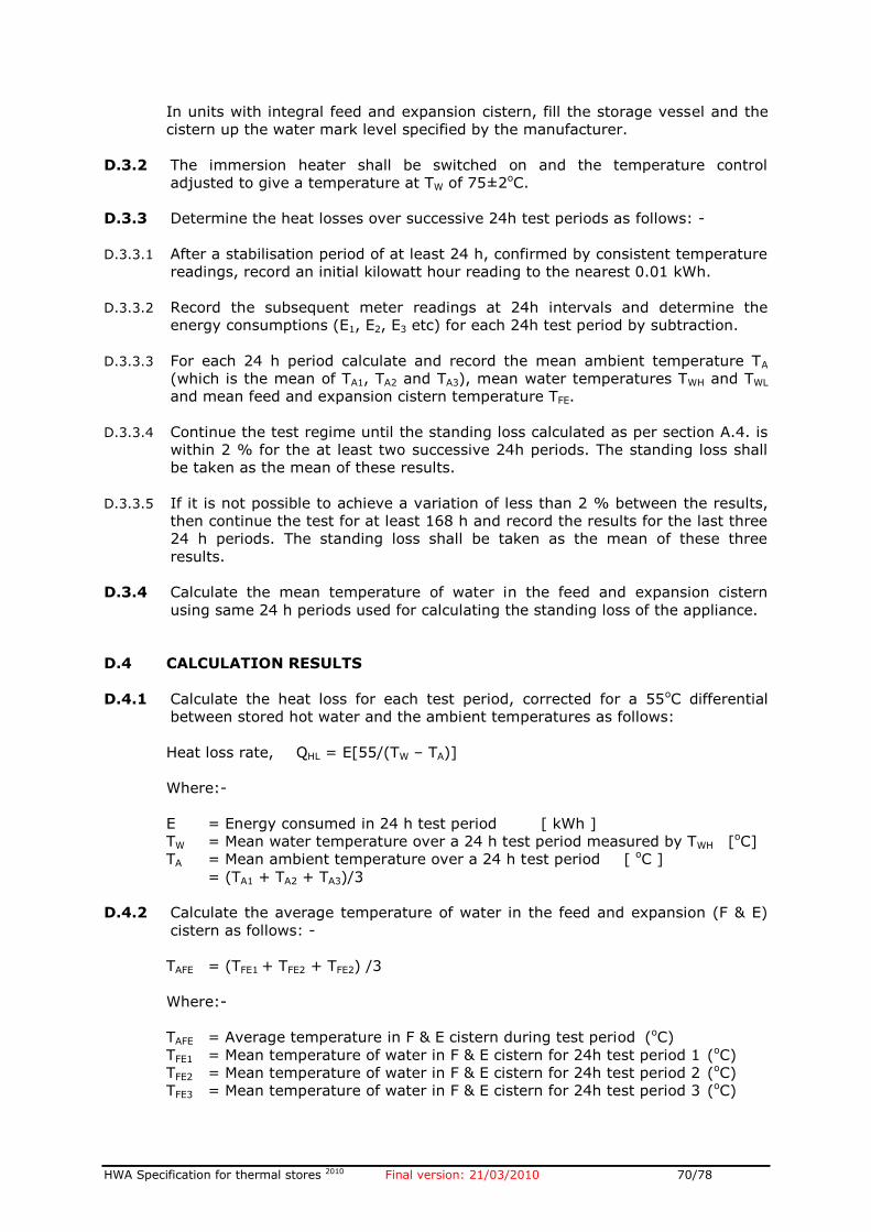
HWA Specification for thermal stores 2010 Final version: 21/03/2010 70/78
In units with integral feed and expansion cistern, fill the storage vessel and the
cistern up the water mark level specified by the manufacturer.
D.3.2 The immersion heater shall be switched on and the temperature control
adjusted to give a temperature at TW of 75±2oC.
D.3.3 Determine the heat losses over successive 24h test periods as follows: -
D.3.3.1 After a stabilisation period of at least 24 h, confirmed by consistent temperature
readings, record an initial kilowatt hour reading to the nearest 0.01 kWh.
D.3.3.2 Record the subsequent meter readings at 24h intervals and determine the
energy consumptions (E1, E2, E3 etc) for each 24h test period by subtraction.
D.3.3.3 For each 24 h period calculate and record the mean ambient temperature TA
(which is the mean of TA1, TA2 and TA3), mean water temperatures TWH and TWL
and mean feed and expansion cistern temperature TFE.
D.3.3.4 Continue the test regime until the standing loss calculated as per section A.4. is
within 2 % for the at least two successive 24h periods. The standing loss shall
be taken as the mean of these results.
D.3.3.5 If it is not possible to achieve a variation of less than 2 % between the results,
then continue the test for at least 168 h and record the results for the last three
24 h periods. The standing loss shall be taken as the mean of these three
results.
D.3.4 Calculate the mean temperature of water in the feed and expansion cistern
using same 24 h periods used for calculating the standing loss of the appliance.
D.4 CALCULATION RESULTS
D.4.1 Calculate the heat loss for each test period, corrected for a 55oC differential
between stored hot water and the ambient temperatures as follows:
Heat loss rate, QHL = E[55/(TW – TA)]
Where:-
E = Energy consumed in 24 h test period [ kWh ]
TW = Mean water temperature over a 24 h test period measured by TWH [oC]
TA = Mean ambient temperature over a 24 h test period [ oC ]
= (TA1 + TA2 + TA3)/3
D.4.2 Calculate the average temperature of water in the feed and expansion (F & E)
cistern as follows: -
TAFE = (TFE1 + TFE2 + TFE2) /3
Where:-
TAFE = Average temperature in F & E cistern during test period (oC)
TFE1 = Mean temperature of water in F & E cistern for 24h test period 1 (oC)
TFE2 = Mean temperature of water in F & E cistern for 24h test period 2 (oC)
TFE3 = Mean temperature of water in F & E cistern for 24h test period 3 (oC)
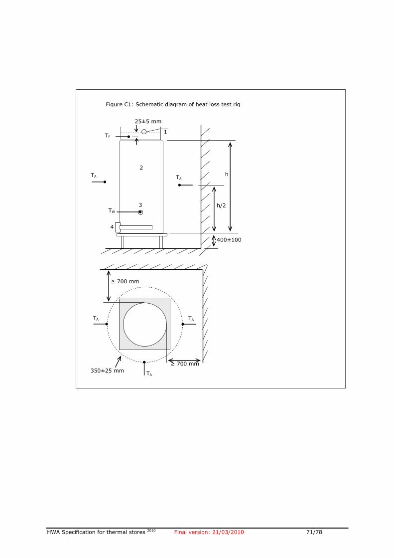
HWA Specification for thermal stores 2010 Final version: 21/03/2010 71/78
Figure C1: Schematic diagram of heat loss test rig
350±25 mm
TA
1
TA
2
TA
3
≥ 700 mm
≥ 700 mm
TW
400±100
h/2
h TA
2
TA
1
2
1
3
4
TF
E
25±5 mm
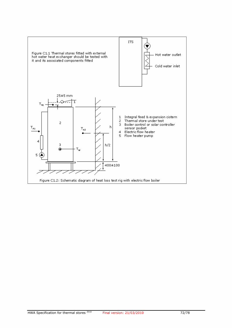
HWA Specification for thermal stores 2010 Final version: 21/03/2010 72/78
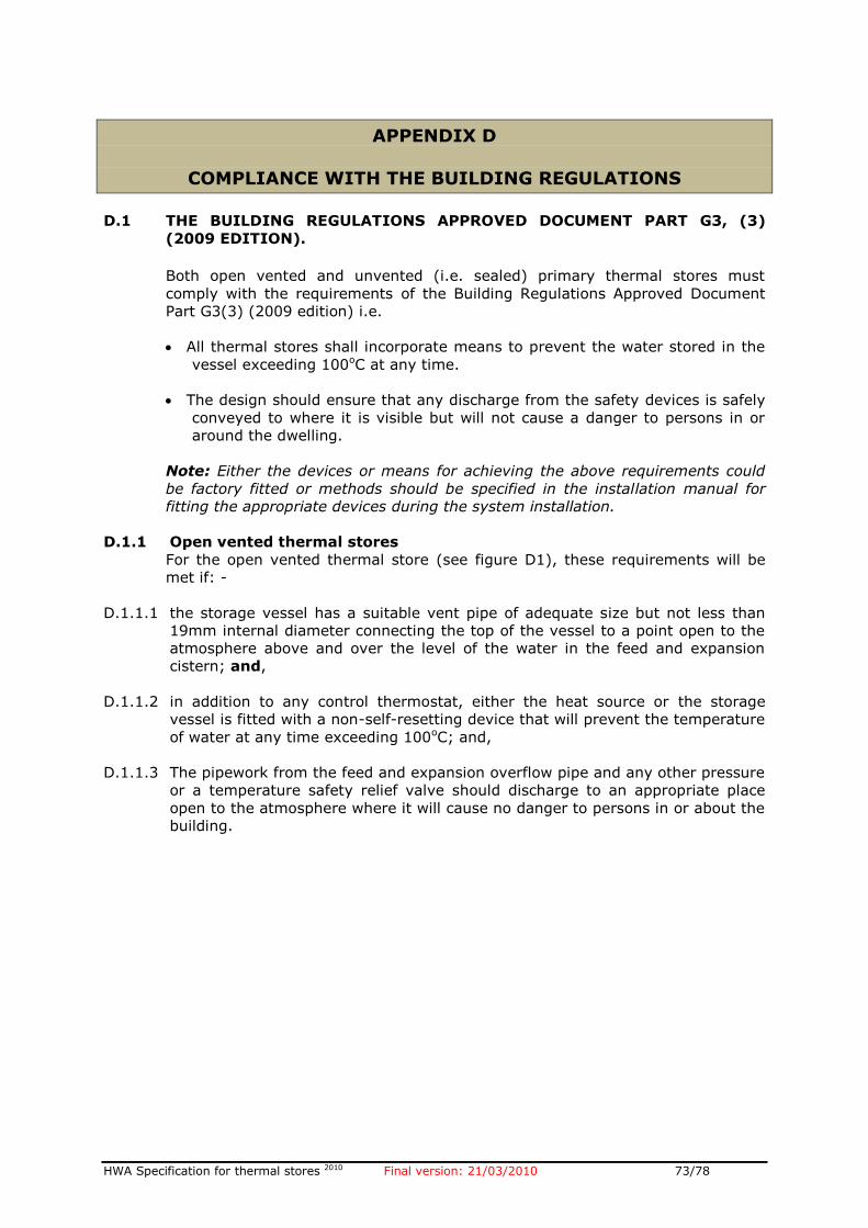
HWA Specification for thermal stores 2010 Final version: 21/03/2010 73/78
APPENDIX D
COMPLIANCE WITH THE BUILDING REGULATIONS
D.1 THE BUILDING REGULATIONS APPROVED DOCUMENT PART G3, (3)
(2009 EDITION).
Both open vented and unvented (i.e. sealed) primary thermal stores must
comply with the requirements of the Building Regulations Approved Document
Part G3(3) (2009 edition) i.e.
All thermal stores shall incorporate means to prevent the water stored in the
vessel exceeding 100oC at any time.
The design should ensure that any discharge from the safety devices is safely
conveyed to where it is visible but will not cause a danger to persons in or
around the dwelling.
Note: Either the devices or means for achieving the above requirements could
be factory fitted or methods should be specified in the installation manual for
fitting the appropriate devices during the system installation.
D.1.1 Open vented thermal stores
For the open vented thermal store (see figure D1), these requirements will be
met if: -
D.1.1.1 the storage vessel has a suitable vent pipe of adequate size but not less than
19mm internal diameter connecting the top of the vessel to a point open to the
atmosphere above and over the level of the water in the feed and expansion
cistern; and,
D.1.1.2 in addition to any control thermostat, either the heat source or the storage
vessel is fitted with a non-self-resetting device that will prevent the temperature
of water at any time exceeding 100oC; and,
D.1.1.3 The pipework from the feed and expansion overflow pipe and any other pressure
or a temperature safety relief valve should discharge to an appropriate place
open to the atmosphere where it will cause no danger to persons in or about the
building.
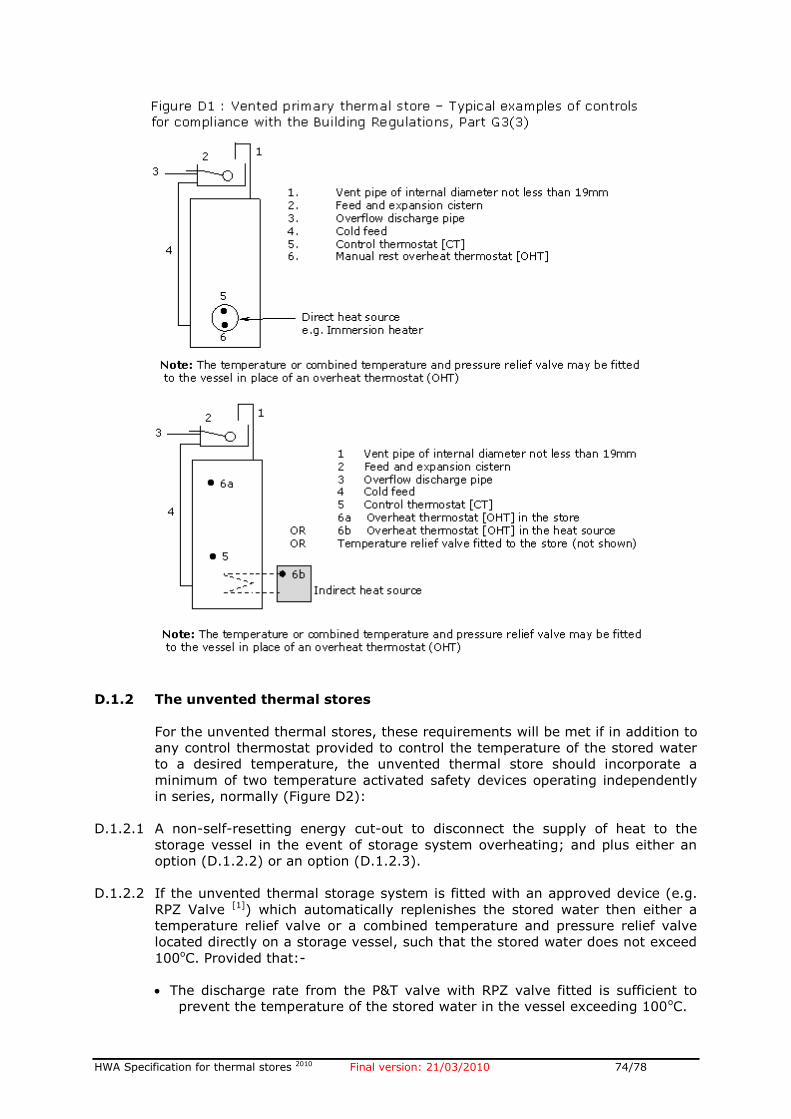
HWA Specification for thermal stores 2010 Final version: 21/03/2010 74/78
D.1.2 The unvented thermal stores
For the unvented thermal stores, these requirements will be met if in addition to
any control thermostat provided to control the temperature of the stored water
to a desired temperature, the unvented thermal store should incorporate a
minimum of two temperature activated safety devices operating independently
in series, normally (Figure D2):
D.1.2.1 A non-self-resetting energy cut-out to disconnect the supply of heat to the
storage vessel in the event of storage system overheating; and plus either an
option (D.1.2.2) or an option (D.1.2.3).
D.1.2.2 If the unvented thermal storage system is fitted with an approved device (e.g.
RPZ Valve [1]) which automatically replenishes the stored water then either a
temperature relief valve or a combined temperature and pressure relief valve
located directly on a storage vessel, such that the stored water does not exceed
100oC. Provided that:-
The discharge rate from the P&T valve with RPZ valve fitted is sufficient to
prevent the temperature of the stored water in the vessel exceeding 100oC.
HWA Specification for thermal stores 2010 Final version: 21/03/2010 75/78
The thermal store package fitted with these devices is approved by the
appropriate approved test house.
Note: Since the introduction of the Water Supply (Water Fittings) Regulations 1999 in England and Wales and the Water Bylaws 2000 in Scotland, it is permitted to use the backflow prevention device instead of an air gap for category 1 fluid, at certain risk levels. A reduced pressure zone (RPZ) valve is an example of such backflow prevention device.
D.1.2.3 If the unvented thermal storage system has no provision to automatically
replenish the stored water then there should be a second non-self-resetting
energy cut-out, which stops the flow of energy from the heat source to the
thermal store using alternative and independent of method (D.1.2.1), such that
the stored water does not exceed 100oC.
D.1.2.4 Unvented thermal storage systems up to 500 litre capacity and 45kW power
input should be in the form of a package. The package and the components
should be appropriate to the appropriate to the circumstances in which they are
used and should be approved by an accredited third party product conformity
certification scheme.
D.1.2.5 Unvented thermal storage systems over 500 litre capacity or over 45kW power
input will generally be bespoke designs for specific projects and as such are
inappropriate for approval by the third party. Where this is the case, the
unvented thermal store should be designed to satisfy the requirements,
(D.1.2.1) to (D.1.2.3) above, by an appropriately qualified engineer.
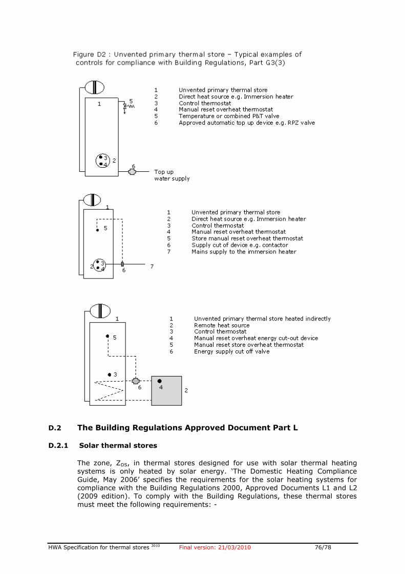
HWA Specification for thermal stores 2010 Final version: 21/03/2010 76/78
D.2 The Building Regulations Approved Document Part L D.2.1 Solar thermal stores
The zone, ZDS, in thermal stores designed for use with solar thermal heating
systems is only heated by solar energy. ‘The Domestic Heating Compliance
Guide, May 2006’ specifies the requirements for the solar heating systems for
compliance with the Building Regulations 2000, Approved Documents L1 and L2
(2009 edition). To comply with the Building Regulations, these thermal stores
must meet the following requirements: -
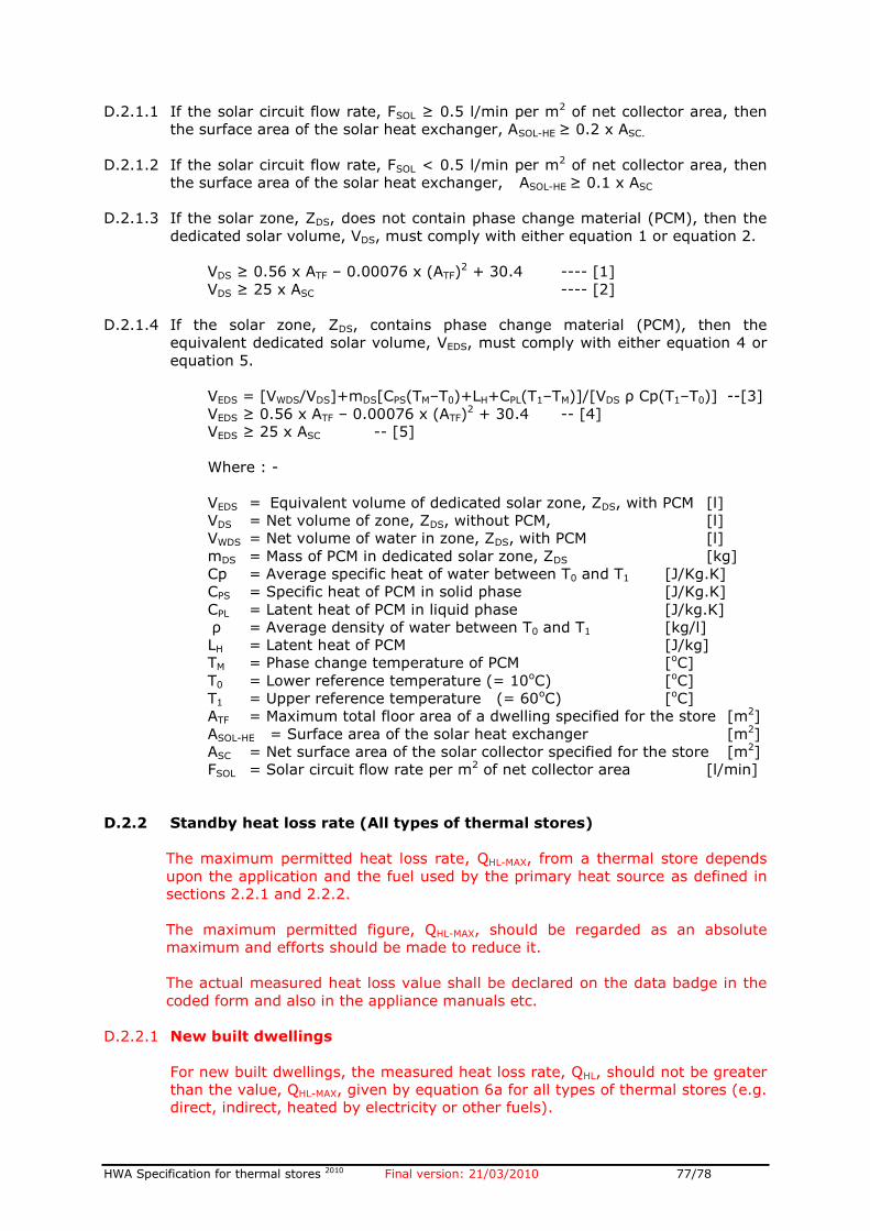
HWA Specification for thermal stores 2010 Final version: 21/03/2010 77/78
D.2.1.1 If the solar circuit flow rate, FSOL ≥ 0.5 l/min per m2 of net collector area, then
the surface area of the solar heat exchanger, ASOL-HE ≥ 0.2 x ASC.
D.2.1.2 If the solar circuit flow rate, FSOL < 0.5 l/min per m2 of net collector area, then
the surface area of the solar heat exchanger, ASOL-HE ≥ 0.1 x ASC
D.2.1.3 If the solar zone, ZDS, does not contain phase change material (PCM), then the
dedicated solar volume, VDS, must comply with either equation 1 or equation 2.
VDS ≥ 0.56 x ATF – 0.00076 x (ATF)2 + 30.4 ---- [1]
VDS ≥ 25 x ASC ---- [2]
D.2.1.4 If the solar zone, ZDS, contains phase change material (PCM), then the
equivalent dedicated solar volume, VEDS, must comply with either equation 4 or
equation 5.
VEDS = [VWDS/VDS]+mDS[CPS(TM–T0)+LH+CPL(T1–TM)]/[VDS ρ Cp(T1–T0)] --[3]
VEDS ≥ 0.56 x ATF – 0.00076 x (ATF)2 + 30.4 -- [4]
VEDS ≥ 25 x ASC -- [5]
Where : -
VEDS = Equivalent volume of dedicated solar zone, ZDS, with PCM [l]
VDS = Net volume of zone, ZDS, without PCM, [l]
VWDS = Net volume of water in zone, ZDS, with PCM [l]
mDS = Mass of PCM in dedicated solar zone, ZDS [kg]
Cp = Average specific heat of water between T0 and T1 [J/Kg.K]
CPS = Specific heat of PCM in solid phase [J/Kg.K]
CPL = Latent heat of PCM in liquid phase [J/kg.K]
ρ = Average density of water between T0 and T1 [kg/l]
LH = Latent heat of PCM [J/kg]
TM = Phase change temperature of PCM [oC]
T0 = Lower reference temperature (= 10oC) [oC]
T1 = Upper reference temperature (= 60oC) [oC]
ATF = Maximum total floor area of a dwelling specified for the store [m2]
ASOL-HE = Surface area of the solar heat exchanger [m2]
ASC = Net surface area of the solar collector specified for the store [m2]
FSOL = Solar circuit flow rate per m2 of net collector area [l/min]
D.2.2 Standby heat loss rate (All types of thermal stores)
The maximum permitted heat loss rate, QHL-MAX, from a thermal store depends
upon the application and the fuel used by the primary heat source as defined in
sections 2.2.1 and 2.2.2.
The maximum permitted figure, QHL-MAX, should be regarded as an absolute
maximum and efforts should be made to reduce it.
The actual measured heat loss value shall be declared on the data badge in the
coded form and also in the appliance manuals etc.
D.2.2.1 New built dwellings
For new built dwellings, the measured heat loss rate, QHL, should not be greater
than the value, QHL-MAX, given by equation 6a for all types of thermal stores (e.g.
direct, indirect, heated by electricity or other fuels).
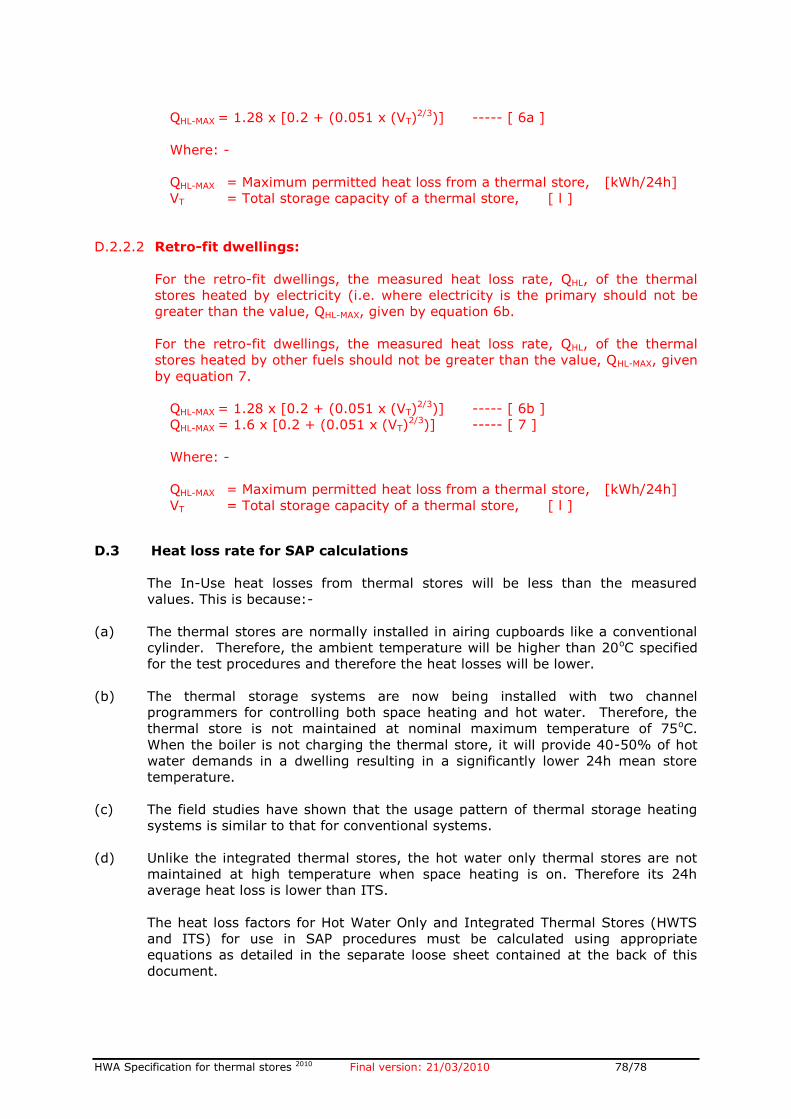
HWA Specification for thermal stores 2010 Final version: 21/03/2010 78/78
QHL-MAX = 1.28 x [0.2 + (0.051 x (VT)2/3)] ----- [ 6a ]
Where: -
QHL-MAX = Maximum permitted heat loss from a thermal store, [kWh/24h]
VT = Total storage capacity of a thermal store, [ l ]
D.2.2.2 Retro-fit dwellings:
For the retro-fit dwellings, the measured heat loss rate, QHL, of the thermal
stores heated by electricity (i.e. where electricity is the primary should not be
greater than the value, QHL-MAX, given by equation 6b.
For the retro-fit dwellings, the measured heat loss rate, QHL, of the thermal
stores heated by other fuels should not be greater than the value, QHL-MAX, given
by equation 7.
QHL-MAX = 1.28 x [0.2 + (0.051 x (VT)2/3)] ----- [ 6b ]
QHL-MAX = 1.6 x [0.2 + (0.051 x (VT)2/3)] ----- [ 7 ]
Where: -
QHL-MAX = Maximum permitted heat loss from a thermal store, [kWh/24h]
VT = Total storage capacity of a thermal store, [ l ]
D.3 Heat loss rate for SAP calculations
The In-Use heat losses from thermal stores will be less than the measured
values. This is because:-
(a) The thermal stores are normally installed in airing cupboards like a conventional
cylinder. Therefore, the ambient temperature will be higher than 20oC specified
for the test procedures and therefore the heat losses will be lower.
(b) The thermal storage systems are now being installed with two channel
programmers for controlling both space heating and hot water. Therefore, the
thermal store is not maintained at nominal maximum temperature of 75oC.
When the boiler is not charging the thermal store, it will provide 40-50% of hot
water demands in a dwelling resulting in a significantly lower 24h mean store
temperature.
(c) The field studies have shown that the usage pattern of thermal storage heating
systems is similar to that for conventional systems.
(d) Unlike the integrated thermal stores, the hot water only thermal stores are not
maintained at high temperature when space heating is on. Therefore its 24h
average heat loss is lower than ITS.
The heat loss factors for Hot Water Only and Integrated Thermal Stores (HWTS
and ITS) for use in SAP procedures must be calculated using appropriate
equations as detailed in the separate loose sheet contained at the back of this
document.

Performance Specificationfor Thermal Stores
Direct integrated thermal stores
Indirect integrated thermal stores
Hot water thermal stores
Buffer stores