Embed Size (px)
Citation preview

*The work has been carried out during the time at the Swiss Federal Institute of Technology Zurich
Performance testing of high voltage generator- and motor insulation systems
RUBEN VOGELSANG
ABB Switzerland Ltd., High Voltage Products* Brown Boveri-Str. 5, 8050 Zurich, SWITZERLAND
BERNHARD FRUTH, OLIVER DUCRY
PD Tech Power Engineering AG Seestrasse 14b, 5432 Neuenhof, SWITZERLAND
Abstract: - High voltage rotating machines remain to play a significant role in generating electrical energy. One of the main causes for down times of these machines is related to problems in the winding insulation. The deregulated energy market leads to cost pressure on the producers of the insulations and the utilities. While manufacturers built insulations with increased electric field, utilities want to reduce costs through longer maintenance intervals and a higher lifetime of the machines. Improvements of insulations and a long failure-free lifetime can only be achieved when a complex mix of measures is applied. This paper describes a mix of techniques that are all suited to achieve a long lifetime of the insulations. Among them is a new method that allows testing of manufacturing quality of the insulation with only few material efforts, visual inspections, the measurement of loss factor and PD measurements. Key-Words: - Winding, Insulation, Generator, Motor, Partial discharges, Lifetime, Aeging, Treeing, Monitoring 1 Introduction Owners of electrical machines expect a high reliability and a long lifetime of its equipment. This can only be achieved by a consistent quality assurance throughout the whole product life cycle on both, the product- and process level. The product level includes design, the raw materials itself and its combination to the final insulation system. The process level includes research and development, production, quality, in-factory testing, commission-ning as well as on- and off-line testing in service.
Winding insulations for high voltage rotating machines consists of three basic components, which is mica that is resistant against partial discharges and tree growth, a support material that gives mechanical strength and a binder resin that fills voids between the mica and the support material. The single components are produced as tapes that are wrapped around the conductor to form the insulation [1, 2]. In order to avoid air inclusions, the latter between the mica tapes are filled with binder resin (bitumen in older insulations). For this purpose, two technologies, resin rich and vacuum pressure impregnation (VPI) are used [1]. After having formed the insulation, the bar is finished with a corona protection for the slot and end winding [1].
Whereas there are some experiences for different raw materials of winding insulations [2–6], the influence of the processing on lifetime has still not been conclusively described. In particular, the influence of different manufacturing qualities and type of manufacturing on the material properties and on time to breakdown is not fully understood [7].
Manufacturers reduce design margins to cut cost and to increase equipment performance. Eventually, the stresses to the insulation systems are increased. Some sources report that more than 30% of motor breakdowns are caused by insulating problems [8–10]. To avoid costs, which are especially high at outages of the power station, testing of the insulations becomes more and more important. Since the insulation system of high voltage rotating machines are of a very complex nature, a high reliability of the machines can only be achieved by applying a complex number of measures.
This paper describes very new and experienced test- and analysis methods, which are all suited to increase lifetime and availability of the insulations. In detail, methods are described for verification of performance of new materials and manufacturing processes as well as diagnosis methods for operating equipment, suited to achieve life extension and/or to reach an early identification of pending problems.
Proc. of the 5th WSEAS/IASME Int. Conf. on Electric Power Systems, High Voltages, Electric Machines, Tenerife, Spain, December 16-18, 2005 (pp136-142)

2 Verification of performance of new materials
2.1 Standard test method according to
IEEE 1043 Current test procedures for electrical insulation systems include electrical, thermal, mechanical and environmental factors as single- sequential- or multifactor load [11, 12]. The test specimens are representative for the bars as used in the machines. They are therefore prepared with outer conductive- and stress grading coating, such as shown in Fig.1.
Fig.1: Specification of a test of form wound bars and coils according to IEEE 1043 Std [12]
The advantage of the test is that it is well accepted, it is standardised and covers the whole insulation, including outer- and endwinding protection. It can so far not been replaced when it comes to customer acceptance tests. However, since it requires an insulation bar for each result, much material is needed to achieve an acceptable statistical evaluation, which limitates that test to be used to assess insulation quality in the production process. 2.2 New test with embedded electrode As seen in Section 2.1, standard ageing tests require much effort. Therefore, newest research results were applied to develop a test method, requiring significantly less material and testing effort [7, 13]. It is based on the result that the main electrical degradation mechanism of winding insulations is electrical tree propagation [7, 13]. In the following, the basic structure, scientific assessment and application of the test method at industrial manufactured winding insulations is described. 2.2.1 Basic structure When tree growth is the main electrical degradation mechanism, insulation properties can be determined by merely measuring the time interval a tree needs to propagate through the material. In order to determine that value, an arrangement with an embedded electrode was developed that causes tree inception immediately after voltage application. That electrode is a copper sheet of 20 x 20 mm2, with a thickness of 0.2 mm. It was embedded into
the material by the manufacturer of the insulation. The edges of the embedded copper sheet have a radius of < 10 µm. It can therefore be ensured that the tree incepts immediately (< 30 s) after voltage application. Since time interval for tree inception is practically zero, the total measured time to breakdown interval is the time interval for tree propagation through the material. From here on, such tests are therefore referred to as “Electrical treeing tests”. A cross section of a winding insulation with embedded electrode is shown in Fig.2, a detailed description of the arrangement is given in [7, 13].
10 mm
Fig.2: Insulation with the embedded high voltage electrode
In each insulation bar, 4 electrodes were uniformly embedded into the material. Therefore, the main advantages of the arrangement are that much less material is required since fewer bars are needed, a material test is presented since tree propagation through the insulation is measured and that certain regions of the bar can be investigated separately [7]. 2.2.2 Similarities and differences to the standard
tests, application of the new test method In order to give a reference to the standard test method, the results of the electrical treeing tests were compared to results with the same type of bars prepared according that as specified in the standards [11, 12, 14]. In the tests with three different insulation systems and constant test conditions, such as the same insulation thickness of 2 mm, the same temperature of 20 ± 5 °C and the same voltage level of 32 kV rms, the results show for all materials that time to breakdown for electrical treeing- and standard tests are not significantly different [7].
Since there are no significantly differences in the results and electrical treeing tests require much less material, they are recommended to extend standard tests for random tests in the production line, determination of residual dielectric strength of bars after service, investigating the tendency of some influencing factors in research laboratories and fingerprint-tests for newly developed material compositions. In addition, they can be used to
Proc. of the 5th WSEAS/IASME Int. Conf. on Electric Power Systems, High Voltages, Electric Machines, Tenerife, Spain, December 16-18, 2005 (pp136-142)

investigate insulation properties at certain regions of the bar to find weak spots of the insulation, such as endwindings, straight sections or conductor edges.
In some cases, such as random tests in the production line, it is impossible to insert the embedded electrode during the wrapping process as described in Section 2.2.1. A method was therefore developed to place the copper sheet in the winding insulation on a completely manufactured bar. In a first step, a gap with a diameter between 10 and 20 mm has to be milled into the insulation. Then, a copper sheet of 0.2 mm thickness must be introduced on the gap surface and attached. In order to avoid surface discharges during the high voltage tests, the gap and the copper sheet must be molded in epoxy resin.
To ensure that the results with this arrangement are representative, tests with subsequent introduced electrodes were carried out and compared to that of treeing tests with a wrapped electrode. Two materials with different time to breakdown values were chosen. Voltage level, temperature and insulation thickness were chosen to be the same as in Section 2.2.2 for both materials. The results are compared in the Weibull-plot in Fig.3.
1
10
100
1000
Wrapped Subsequentintroduced
Wrapped Subsequentintroduced
Material 1 Material 2
63%
-val
ue o
f ti
me
to b
reak
dow
n [h
]
Fig.3: Time to breakdown values of treeing tests with wrapped- and subsequent introduced electrode
2.2.3 Tests at industrial manufactured winding
insulations To apply the new method, tests at industrially manufactured bars have been carried out. These bars differ in type of taping and production company. To compare the results, reference insulations were made. Fig.4 shows the Weibull-plot for the time to breakdown values for the insulations tested.
The results in Fig.4 show that there is a significant difference in the time to breakdown values for material 2 as the confidential intervals do not overlap. That proves that industrial manufac-turing of company 2 is of a poor quality. In contrast, no significant difference in time to breakdown was measured for material 3 as the confidence intervals
do overlap. This shows that the manufacturing of material 3, company I is of a good quality.
0.001
0.01
0.1
1
10
100
1000
Referencemanufacturing
Company 1 Referencemanufacturing
Company I Referencemanufacturing
Company A Company B
Material 2 Material 3 Material 4
63%
-val
ue o
f ti
me
to b
reak
dow
n [h
]
Fig.4 Time to breakdown values at winding insulations at different manufacturing
A somewhat different picture shows material 4. Whereas company A is able to produce that insulation in a similar quality than the reference insulation, is the material of company B of a rather poor quality as the time to breakdown values show. The reason for the significant different time to breakdown values can be found in the microscopic properties of the insulation. Figs.5 to 11 show a representative example of the insulation quality of the materials in the same order as given in Fig.4.
1 mm
Fig. 5: Structure of material 2 at reference manufacturing
1 mm
Voids anddelaminations
Fig. 6: Structure of material 2 at manufacturing of company 1
500 µm
Fig. 7: Structure of material 3 at reference manufacturing
500 µm
Fig. 8: Structure of material 3 at manufacturing of company I
Proc. of the 5th WSEAS/IASME Int. Conf. on Electric Power Systems, High Voltages, Electric Machines, Tenerife, Spain, December 16-18, 2005 (pp136-142)

500 µm
Fig. 9: Structure of material 4 at reference manufacturing
500 µm
Fig. 10: Structure of material 4 at manufacturing of company A
1 mmDelaminations
of tape layers
Fig. 11: Structure of material 4 at manufacturing of company B
The micrographs clearly show that all reference materials are without any voids or imperfections. Also, material 3, company I and material 4, company A have similar structure as the material at reference manufacturing. In contrast, both materials that show many voids and delaminations in the insulation have the significantly reduced time to breakdown values, such as material 2, company 1 (Fig.6) and material 4, company B (Fig.11).
The reason for such a difference is supposed to be the different attachment of the tapes. Both systems were taped by hand and it is supposed that at hand taping, it is not possible to have such a constant taping strength as with machine taping. This can lead to a loose attachment of the tapes and the binder resin cannot fill the regions between the tapes sufficiently. In that area, an electrical tree can propagate very quickly along, thus causing very short time to breakdown values as measured. The breakdown values and the micrographs confirm a significant influence of the taping on potential lifetime of winding insulations.
Since material 4 is a VPI and material 2 a resin rich insulation, the results of Fig.4 show that the sensibility for poor preparation is much more severe for resin rich than for VPI-insulations and those tolerances in taping are more critical for resin rich insulations than for VPI-materials.
3 Diagnosis and life extension of operating equipment in service
3.1 Visual inspection of endwindings One of the most commonly discharge sources in rotating machines is the so called endwinding discharge. This surface discharge generally occurs on the field grading varnishes and is caused by different reasons, such as surface contamination, inadequate coating properties or degradation of conducting properties of the field grading material. The task of field grading is to minimise the surface field strength by establishing a practically constant potential gradient. In comparison to conductivity measurements, surface potential distribution mapping represents an effective way to compare different materials. An appropriate field grading substance may avoid long-term corrosion or damage produced by discharges. Fig.12 and Fig.13 compare two commercial grading materials.
Fig.12: Surface potential distribution with optimum grading effect (z: potential, x: length)
Fig.13: Surface potential distribution with insufficient grading effect (z: potential, x: length)
An insufficient grading leads to a material corrosion by continuous partial discharge activity. In a latter stage, the surface may strongly be eroded and the electrical field distribution may completely deviate from its original state, thus causing discharges parallel to the insulator surface and in a vertical direction to metal parts. In order to identify end-winding problems, it has to be looked for white traces, such as shown in Figs. 14 and 15. In addition to an off-line visual inspection, on-line ultrasonic detection is a standard technique to localise surface discharges, where UV sensitive camera systems can
Proc. of the 5th WSEAS/IASME Int. Conf. on Electric Power Systems, High Voltages, Electric Machines, Tenerife, Spain, December 16-18, 2005 (pp136-142)

help to rapidly pin-point the location of discharge during high voltage tests and to precisely locate and analyse the origin of a discharge in order to help to define confined defect oriented repair measures.
Fig.14: White traces at endwinding due to corona degradation
Fig.15: Severe degradation due to spark discharges caused by ageing of the semi-conducting coating at an endwinding
3.2 AC loss factor The dielectric loss of a high voltage rotating machine insulation may have different independent physical origins that are also depending on the dielectric properties of the material and the partial discharges (PD). The individual contribution of each different dissipation mechanism to the dielectric loss depends on the nature, the severity and the time of operation of a machine but also on the structural state of the insulation and especially the impregna-ting resin. The loss of dipolar origin hardly varies with voltage (the dipolar loss mainly depends on the structural state of the resin, e.g. age or polymeri-sation). The losses due to partial discharge activity and field grading materials are field dependent. 3.3 Partial discharges 2.2.1 Off-line PD measurements Off-line Partial discharge activity is detected in conjunction with tan δ measurements by using the phase resolving partial discharge acquisition technique (PRPDA). The core data acquisition of the PRPD is based on an event recording concept, where the PRPD generates patterns that represent a three-dimensional distribution function with the coordinates high voltage phase angle, signal amplitude and event number. These patterns are represented as colour-pictured fingerprints or so called “partial discharge patterns” [15–17].
Other than the dielectric loss factor, PD patterns are direct measures of the PD activity. In the first place, PD indicates defects and stresses in the rotating machine, e.g. defects created by abrasion of insula-ting materials or surface contamination. In addition, PD measurements reveal locally confined defects, which would otherwise get lost in the bulk signal. Since the shape of a pattern is usually related to a defect and its geometry, PD patterns allow in most situations to identify the most prominent defects, recognise superimposed of defects and distinguish noise from disturbance. Some examples of PD patterns are shown in Figs.16 and 17. Typically, the internal discharge in Fig.16 (triangular shape) dominates at lower voltages and its level is hardly voltage dependent. At higher voltages the surface discharge, Fig.17, dominates. Whereas in Figs.16 and 17 the single effect is shown, illustrate Figs. 18 and 19 typical superimpositions of both effects.
Fig.16: PD-pattern of a discharge in a delamination
Fig.17: PD-Pattern of a surface discharge in an endwinding
Fig.18: Superimposed internal and surface discharge pattern I
Fig.19: Superimposed internal and surface discharge pattern II
Proc. of the 5th WSEAS/IASME Int. Conf. on Electric Power Systems, High Voltages, Electric Machines, Tenerife, Spain, December 16-18, 2005 (pp136-142)
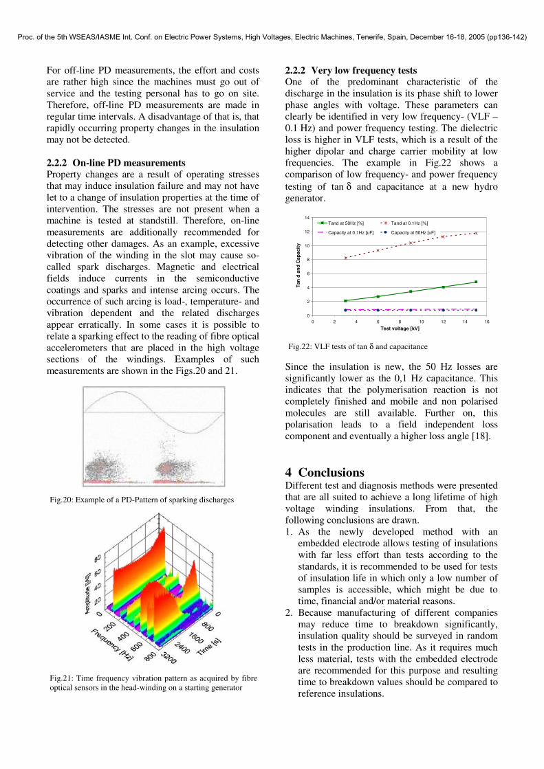
For off-line PD measurements, the effort and costs are rather high since the machines must go out of service and the testing personal has to go on site. Therefore, off-line PD measurements are made in regular time intervals. A disadvantage of that is, that rapidly occurring property changes in the insulation may not be detected. 2.2.2 On-line PD measurements Property changes are a result of operating stresses that may induce insulation failure and may not have let to a change of insulation properties at the time of intervention. The stresses are not present when a machine is tested at standstill. Therefore, on-line measurements are additionally recommended for detecting other damages. As an example, excessive vibration of the winding in the slot may cause so-called spark discharges. Magnetic and electrical fields induce currents in the semiconductive coatings and sparks and intense arcing occurs. The occurrence of such arcing is load-, temperature- and vibration dependent and the related discharges appear erratically. In some cases it is possible to relate a sparking effect to the reading of fibre optical accelerometers that are placed in the high voltage sections of the windings. Examples of such measurements are shown in the Figs.20 and 21.
Fig.20: Example of a PD-Pattern of sparking discharges
Fig.21: Time frequency vibration pattern as acquired by fibre optical sensors in the head-winding on a starting generator
2.2.2 Very low frequency tests One of the predominant characteristic of the discharge in the insulation is its phase shift to lower phase angles with voltage. These parameters can clearly be identified in very low frequency- (VLF – 0.1 Hz) and power frequency testing. The dielectric loss is higher in VLF tests, which is a result of the higher dipolar and charge carrier mobility at low frequencies. The example in Fig.22 shows a comparison of low frequency- and power frequency testing of tan δ and capacitance at a new hydro generator.
0
2
4
6
8
10
12
14
0 2 4 6 8 10 12 14 16
Test voltage [kV]
Tan
d an
d C
apac
ity
Tand at 50Hz [%] Tand at 0.1Hz [%]
Capacity at 0.1Hz [uF] Capacity at 50Hz [uF]
Fig.22: VLF tests of tan δ and capacitance Since the insulation is new, the 50 Hz losses are significantly lower as the 0,1 Hz capacitance. This indicates that the polymerisation reaction is not completely finished and mobile and non polarised molecules are still available. Further on, this polarisation leads to a field independent loss component and eventually a higher loss angle [18]. 4 Conclusions Different test and diagnosis methods were presented that are all suited to achieve a long lifetime of high voltage winding insulations. From that, the following conclusions are drawn. 1. As the newly developed method with an
embedded electrode allows testing of insulations with far less effort than tests according to the standards, it is recommended to be used for tests of insulation life in which only a low number of samples is accessible, which might be due to time, financial and/or material reasons.
2. Because manufacturing of different companies may reduce time to breakdown significantly, insulation quality should be surveyed in random tests in the production line. As it requires much less material, tests with the embedded electrode are recommended for this purpose and resulting time to breakdown values should be compared to reference insulations.
Proc. of the 5th WSEAS/IASME Int. Conf. on Electric Power Systems, High Voltages, Electric Machines, Tenerife, Spain, December 16-18, 2005 (pp136-142)

3. Since partial discharge measurements indicate the presence of locally confined defects, the results can be associated to different defect types.
4. In an off-line inspection, the combination of the procedures partial discharge (PD) measurements, AC loss factor, very low frequency tests and visual inspection allow a fairly precise determination of the machine condition and are therefore strongly recommended.
5. Since off-line tests do not show all defects, they have to be complemented by on-line PD localisation attempts using electromagnetic or ultrasonic probes.
6. In critical cases, periodic on-line PD testing or permanent PD monitoring should be applied to reassure the findings of the off-line tests in order to identify operation-caused damage scenarios or to allow an early warning in case of (sudden) defects.
References [1] H. Schaumburg, „Werkstoffe und Bauelemente der
Elektrotechnik: Polymere“, Verlag B.G. Teubner, Stuttgart, Germany, ISBN: 3-519-06145-7, 1997
[2] K. Kimura, Y. Kaneda, “The Role of Microscopic Defects in Multistress Aging of Micaceous Insulation”, IEEE Trans. on DEI, vol. 2, no. 3, pp. 426–432, Jun. 1995
[3] L. A. Dissado, G. C. Fothergill, “Electrical degradation and breakdown in polymers”, Peter Peregrinus Ltd., London, UK, ISBN: 0 86341 196 7, 1992
[4] K. Hee Dong, J. Young Ho, R. Hong Woo, “Effect of aging on the microstructure evolution, thermal and mechanical properties of mica/epoxy composite”, IEEE Conf. on El. Insul. and Diel. Phen., CEIDP, Austin, USA, pp. 537–541, Oct. 1999
[5] M. R. Naghashan, “Untersuchungen zur Teilentladungsaktivität von maschinentypischen Hochspannungsisolierungen”, Doctoral Thesis, University of Dortmund, Germany, Shaker Verlag Aachen, 1996
[6] H. Mitsui, Y. Inoue, “Statistical analysis on the electrical failure properties of the form-wound insulations systems for rotating machines”, IEEE Trans. on EI, vol. EI-8, no.3, pp. 109–113, 1977
[7] R. Vogelsang, R. Brütsch, K. Fröhlich, “Effect of electrical tree propagation on breakdown in mica insulations” 13th Int. Symposium on High Voltage Engineering, ISH, Delft, The Netherlands, Conf. Proc., pp. 1–4, Aug. 2003
[8] O. V. Thorsen, M. Dalva, “A survey of faults on induction motors in offshore oil industry, petrochemical industry, gas terminals and oil refineries”, IEEE Trans. on Ind. Appl., vol. 31, no. 5, pp. 1186–1196, Sep./Oct. 1995
[9] IEEE Motor Reliability Working Group, “Report of large motor reliability survey of Industrial and commercial installations, Part I and Part II”, Committee report, IEEE Trans. on Ind. Appl., vol. IA-21, no.4, pp. 853–872, Jul./Aug. 1985
[10] N. Srb, “Erfahrungen mit Stossspannungsprüfungen an elektrischen Maschinen”, Allianz Report 70, Heft 2, pp. 58–62, Apr. 1997
[11] IEC Std 60505, “Evaluation and qualification of electrical insulation systems”, IEC International Standard 60505, Second Edition, 1999
[12] IEEE Std 1043-1996, “IEEE Recommended Practice for Voltage-Endurance Testing of Form-Wound Bars and Coils”, Voltage Endurance Committee of the Dielectrics and Electrical Insulation Soc., Sep. 1996
[13] R. Vogelsang, “Time to breakdown of high voltage winding insulations with respect to microscopic properties and manufacturing qualities”, Doctoral Thesis, Swiss Federal Institute of Technology Zurich, Hartung-Gorre Verlag Konstanz, Germany, ISBN: 3-89649-965-3, 2004
[14] IEEE Std 1553™-2002, “IEEE Trial-Use Standard for Voltage-Endurance Testing of Form-Wound Coils and Bars for Hydro-generators” IEEE Power Engin. Society 2002
[15] B. Fruth, J. Fuhr, “Partial Discharge Pattern Recognition - A Tool for Diagnosis and Monitoring of Aging”, CIGRE, paper 15/33-12, 1990
[16] L. Niemeyer, B. Fruth, F. Gutfleisch, "Simulation of Partial Discharges in Insulation Systems", Proc. 7th Int. Symp. High Voltage Engineering, ISH, Dresden, paper 71.05, 1991
[17] R. Goffaux et al., “Dielectric Test Methods for Rotating Machine Stator Insulation Inspection”, IEEE Conf. on El. Insul. and Diel. Phen., CEIDP, Atlanta, USA, pp. 528 – 533, 1998
[18] B. Fruth, G. Liptak, “Dielectric Properties of Mica Epoxy Composites Subjected to Thermal and Thermoelectrical Aging”, 6th Int. Symp. High Voltage Engineering, New Orleans, USA, paper 21.02. 1998
Proc. of the 5th WSEAS/IASME Int. Conf. on Electric Power Systems, High Voltages, Electric Machines, Tenerife, Spain, December 16-18, 2005 (pp136-142)