Embed Size (px)
Citation preview
ChineseJournal of Aeronautics
Chinese Journal of Aeronautics 20(2007) 539-545www.elsevier.com/locate/cja
Periodic Error Compensation for Quartz MEMS Gyroscope Drift of INS
Xu Jianmaoa, Zhang Haipengb,c,*, Sun Junzhongc
aCollege of Energy and Power Engineering, Huazhong University of Science and Technology, Wuhan 430074, China
bSchool of Instrument Science and Opto-electronics Engineering, Beijing University of Aeronautics and Astronautics, Beijing 100083, China
cMechanical and Electrical Equipment Research Institute, Qingdao Navy Submarine Academe, Qingdao 266071, China
Received 4 July 2007; accepted 3 September 2007
Abstract
In order to improve the navigation accuracy of an inertial navigation system (INS), composed of quartz gyroscopes, the existing real-time
compensation methods for periodic errors in quartz gyroscope drift and the periodic error term relationship between sampled original data and
smoothed data are reviewed. On the base of the results, a new compensation method called using former period characteristics to compensate
latter smoothness data (UFCL for short) method is proposed considering the INS working characteristics. This new method uses the original data
without smoothing to work out an error conversion formula at the INS initial alignment time and then compensate the smoothed data errors by
way of the formula at the navigation time. Both theoretical analysis and experimental results demonstrate that this method is able to cut down on
computational time and raise the accuracy which makes it a better real-time compensation approach for periodic error terms of quartz micro elec-
tronic mechanical system (MEMS) gyroscope’s zero drift.
Keywords: real-time compensation; quartz MEMS gyroscope; periodic error; period characteristic; inertial navigation system (INS)
1 Introduction
Widely used recently though[1-2], the low-cost quartz micro electronic mechanical system (MEMS) gyroscope based on MEMS technique is deficient in accuracy and in continuous working time in a given working situation[3-4]. For example, the continuous working time of the Scud missile is less than 4 min during a flight of 300 km[5], the existing rocket ar-tillery needs 7-12 s to fly 4 000 m and the middle caliber anti-missile artillery only needs 4-6 s to cover the same distance[6]. The periodic error terms are found strong in the quartz gyroscope’s zero drift
*Corresponding author. Tel.: +86-10-82339702. E-mail address: [email protected] items: New Century Program for Excellent Telents (NCET-
04-0162); National Defense Basic Research Program (K1204060116)
under the condition of short working time and highly frequent sampling[7]. Therefore, a precise, real time and online compensation method is needed to decrease these periodic errors to make effective use of quartz series gyroscopes.
After reviewing the principles and characteris-tics of the existing compensation methods, the pe-riodic error term relationship between the sampled original data and the smoothed data is studied. On the base of it, a new compensation method, called using former period characteristics to compensate latter smoothness data (UFCL for short) method is put forward. The conducted experiments show that this method, in addition to meeting the real-time requirements and succeeding in averting the influ-ence from data smoothness, well befits on-line
· 540 · Xu Jianmao et al. / Chinese Journal of Aeronautics 20(2007) 539-545
compensation of the quartz series gyroscope’s zero drift.
2 Characteristics Analysis of Existing Compensation Methods
The inertial navigation system can be divided into three classes, i.e., element, part, and system class. The quartz MEMS gyroscope belongs to the element class and its sampling frequency is about 1 000 Hz or even higher. In the system class, the navigation parameter calculating frequency is as low as about 100 Hz because of its complicated data processing[8]. Therefore, the original sampled data in the element class must be firstly smoothed in the part class instead of being directly provided to the system class so as to meet the requirements of fre-quency matching[9].
The existing methods to compensate periodic error terms in the quartz series MEMS gyroscope’s zero drift can be divided into two kinds. Of them one is called compensation first and smoothing be-hind (CS for short) method, which is to compensate periodic error in the element class before the smoothing process by processing the original sam-pled data. Different from it, the other is called smoothing first and compensation behind (SC for short) method which is to compensate periodic error in the system class after the smoothing process by processing the smoothed data.
The two reasons attributable to better adapta-bility of compensation methods of periodic error to the parameters’ changes are: first, although MEMS gyroscopes possess poor performance, such as large long-time drift and bad bias repeatability, it is found that the periodic error parameters of the same gyro-scope are becoming close to each other in different tests[7]; second, when the INS based on MEMS gy-roscopes starts running, all the work, including test-ing, calibration, compensation, initial alignment of the system and the whole navigation work, are required to be completed in a rather short time be-fore the significant changes in the gyroscope drift take place.
2.1 CS method analysis
The process of CS method can be summarized as follows: At initial alignment time, all the periodic error term parameters are calibrated by the original sampled data in the element class. At navigation time, every original sampled datum in the element class is compensated by the calibrated periodic error term parameters followed by smoothing the com-pensated data to match the navigation calculating frequency in the system class.
Taking consideration of involving several dif-ferent cosine functions in the periodic errors of the quartz gyroscope, the periodic errors based on the Fourier transform theory can be described mathe-matically as follows
1( ) cos(2 + )
N
i i ii
y t A f t (1)
where if is the frequency of the ith periodic error term ( 1, ,i N ), iA the amplitude, i the initial phase. Supposing t is the current time, ( )x t the original output data of the drift of the quartz MEMS gyroscope at time t, b ( )x t the data having been compensated at time t, where 1, 2,3,t , then the CS compensation calculation can be described as
b
1
( ) ( ) ( )
( ) cos(2 + )N
i i ii
x t x t y t
x t A f t (2)
From Eq.(2), the CS method contains triangle function calculations which require a long stretch of computational time. The quartz MEMS gyroscope zero drift often includes N different periodic error terms. If the sampling frequency of a gyroscope is 1 000 Hz, 1 000N triangle functions should be tack-led in one second. In many cases, an micro inertial measurement unit (MIMU) is made of three gyro-scopes, which means a huge amount of calculative work posing a formidable challenge to the construc-tion of hardware inclusive of integrated circuits and CPUs.
2.2 SC method analysis
The process of SC method can be summarized as follows: at initial alignment time, all the periodic error item parameters are calibrated by the smo-
Xu Jianmao et al. / Chinese Journal of Aeronautics 20(2007) 539-545 · 541 ·
othed data in the system class; at navigation time, the original sampled data are smoothed to match the navigation calculating frequency followed by com-pensating every smoothed datum in the system class by the calibrated periodic error term parameters.
Supposing the original gyroscope output data before smoothing is ( )mx t , where 1 2, , ,m Mt t t t .After data smoothing, let the new smoothed data series be xp(ti), where 1,2,3,it . Supposing every M original data are smoothed as one datum, the sampling period of original gyroscope output data is
sT , the calculating period of data smoothing cT , then s c( 1) ( 1)m it t T m T
Suppose s( 1)it t T , then
p1
1( ) ( )M
mm
x t x tM
(3)
Supposing the form of an obvious periodic er-ror term is similar to Eq.(1), then the SC compensa-tion calculation can be described by
b p
1 1
( ) ( ) ( )
1 ( ) cos(2 + )M N
m i i im i
x t x t y t
x t A f tM
(4)
From Eq.(3) and Eq.(4), it is clear that the SC method eliminates a large amount of calculative work of the triangle functions thus lightening the burden of the CPU.
But the data smoothing process of SC method may affect the stability of the periodic error term parameters which will exert serious influences on the compensation precision. The smoothing process would prolong the periodic error term period de-creasing its frequency, complicating the low fre-quency components and increasing the number of obviously periodic error terms. These phenomena are described in detail in Ref.[10].
3 Research on a New UFCL Compensa- tion Method
3.1 Introduction of UFCL method
As described above, both CS method and SC method have their serious inherent disadvantages, to overcome which, on the base of the above analysis, a new compensation method, UFCL method, is in-
troduced.The process of the UFCL method can be sum-
marized as follows: at initial alignment time, all the obvious periodic error term parameters are cali-brated by the original sampled data in the element class followed by calculating the compensated pa-rameters of the error-conversion formula by the end of the initial alignment; at navigation time, the original sampled data are smoothed to match the navigation calculating frequency followed by using the error-conversion formula to compensate every smoothed datum in the system class.
3.2 Error-conversion principle and formula
The key of the UFCL method is to find how the original data periodic errors at the element class influence the smoothed data at the system class. Mathematically, it relies on finding out the error- conversion formula.
The periodic errors y(t) in quartz MEMS gyro-scope zero drift usually include N different periodic error terms as shown in Eq.(1). Supposing every Moriginal data are smoothed as one datum, which means that each calculating period sT includes Msampling period cT . Supposing the M sampled data in calculating period sT are ( )mx t , where s( 1)it t T ,the smoothing series is xp(t) with a value b ( )mx t
left behind after the M sampled original data have been compensated, then
b( ) ( ) ( )m m mx t x t y t (5)
Calculate the average value in the it calcula- ting period according to mt in Eq.(5), then
b1 1
1 1
1 1( ) ( )
1 cos(2 + )
M M
m mm m
M N
i i m im i
x t x tM M
A f tM
(6)
where, the left part is xp(t), which stands for the value smoothed from M data in the ti period. The first item in the right is the average value of the Mdata in the ti period which have been compensated. As the UFCL method wants just the precise smoothed data, it is marked by xb(t) which can be used for the navigation calculation. For the second
· 542 · Xu Jianmao et al. / Chinese Journal of Aeronautics 20(2007) 539-545
item in the right of Eq.(6), 1
N
ishould be calcu-
lated before calculating 1
1 M
mM. This calculating
process means that calculating the sum effect of all the N obviously periodic terms on one of the Moriginal data in a calculating period Ts precedes calculating the average value of the above effects of N period on all the M original data.
In brief, the UFCL method is characterized by its calculation process opposite to Eq.(6), viz to
calculate1
1 M
mM first,
1
N
isecond. This process
means the priority given to calculation of the aver-age value of one obvious period effect on all the Moriginal data over the calculation of the sum effect of all the N obviously periodic terms. Then the Eq.(6) should be transformed to
b p1 1
1( ) ( ) cos(2 + )N M
i i m ii m
x t x t A f tM
(7)
Let
1
1( ) cos(2 + )M
i i i m im
p t A f tM
(8)
since the sampling frequency for the testing is in-variable, then
c( 1)mt t m T (9)
Substitute Eq.(9) into Eq.(8),
c1
1( ) { cos[2 +2 ( 1) + ]}M
i i i i im
p t A f t f m TM
(10)
Expand the triangle function in Eq.(10), and trans-form it into
c1
c1
1( ) { cos[2 ( 1) + ]} cos(2 )
1 { sin[2 ( 1) + ]} sin(2 )
M
i i i i im
M
i i i im
p t A f m T f tM
A f m T f tM
(11) Eq.(11) can be marked by
( ) cos(2 ) sin(2 )i i i i ip t C f t S f t (12)
Then
c1
c1
1 { cos[2 ( 1) + ]}
1 { sin[2 ( 1) + ]}
M
i i i im
M
i i i im
C A f m TM
S A f m TM
(13)
All the parameters in the right of Eq.(13) could be got out of line, of which the parameter iA , if
and i could be calibrated precisely from the drift data of the quartz gyroscope[11], and iC and iS
could be calibrated before the compensation. The Eq.(11) can be simply rewritten into
( ) cos(2 )i i i ip t F f t (14)
where2 2 , arctan( / )i i i i i iF C S S C
iF and i could also be calculated out of
line. By way of Eq.(14), the calculative workload can be reduced to half that stated before. The prin-ciple formula of UFCL method can be acquired by substituting Eq.(14) into Eq.(7) as follows
b p1
( ) ( ) [ cos(2 )]N
i i ii
x t x t F f t (15)
3.3 The UFCL method characteristics analysis
From the above analysis, it is obvious that the UFCL method has two positive characteristics.
First, it has high compensation precision, which the CS method possesses but the SC method lacks. The compensated obvious periodic error items emanate from the original sampled data and are never influenced by smoothness.
Second, it has low compensating frequency which the SC method possesses but the CS method lacks. The periodic error is compensated by dealing with the smoothed data in system rather than by dealing with the original sampled data in element.
4 Experimental Analysis
4.1 Compensation experiment design
Four BEI GYROCHIP LCG50 type gyroscopes were chosen as the representatives of the quartz se-ries MEMS gyroscope to compare above-mentioned three compensation methods. The experimental sys-tem included a 920A type single axis velocity turn-table, an Sys-center Module/Super DX type CPU module from Shenzhen Shengbo Company and a PXI-6221 data sampling module. Labview was used as control software to set the sampling frequency and data saved dress.
Xu Jianmao et al. / Chinese Journal of Aeronautics 20(2007) 539-545 · 543 ·
Test conditions were set according to common test standards[12-13]. Through a transition frame, four BEI GYROCHIP LCG50 gyroscopes were fastened to the horizontal surface of the turntable, the sensi-tive axis of which was parallel to the turntable axis. The sampling frequencies were set to 500 Hz, 1 000Hz, 1 500 Hz, 2 000 Hz and 5 000 Hz, data smooth-ing were conducted with 5, 10, 20 and 50 data, and the test results were recorded over as long as 120 s.
4.2 Compensation experiment results
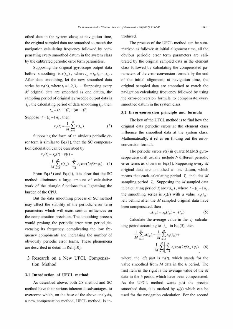
The main criterion to evaluate the real time compensation method is whether the calibrated pa-rameters earlier calculated off-line can be applied on-line effectively. As space was limited, only one quartz gyroscope was taken as an example, in which every 10 data was smoothed in INS with the sam-pling frequency of 1 000 Hz. Fig.1 shows the origi-nal testing data.
Fig.1 Original sampled data.
All the parameters of every obviously periodic error term[11,14] were firstly calibrated by the data over the first 8 s. And then the results were used to compensate all the sampled data over the 120 s by the different methods.
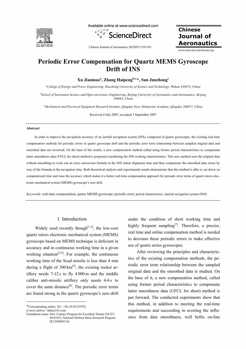
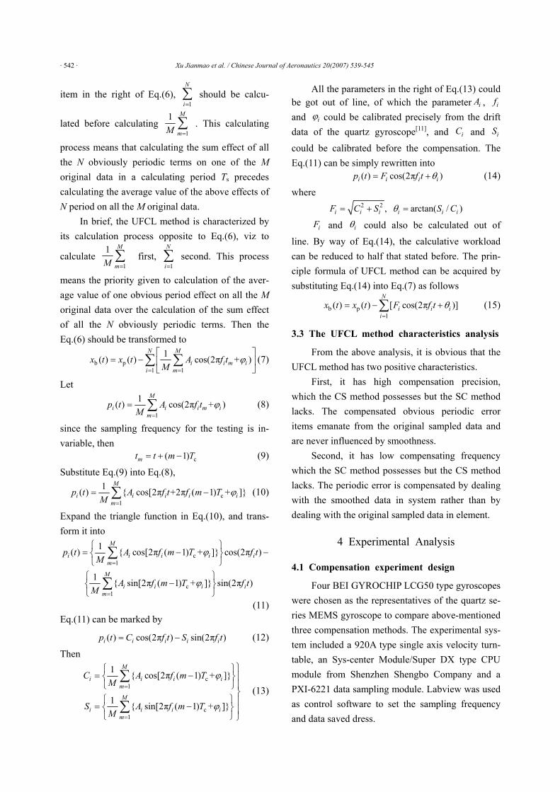
Fig.2 shows the results compensated by the CS method.
Fig.2 Results by CS compensation methods.
The results in Fig.2 appear so stable that the errors do not grow with time and so precise that satisfies the on-line compensation requirements.
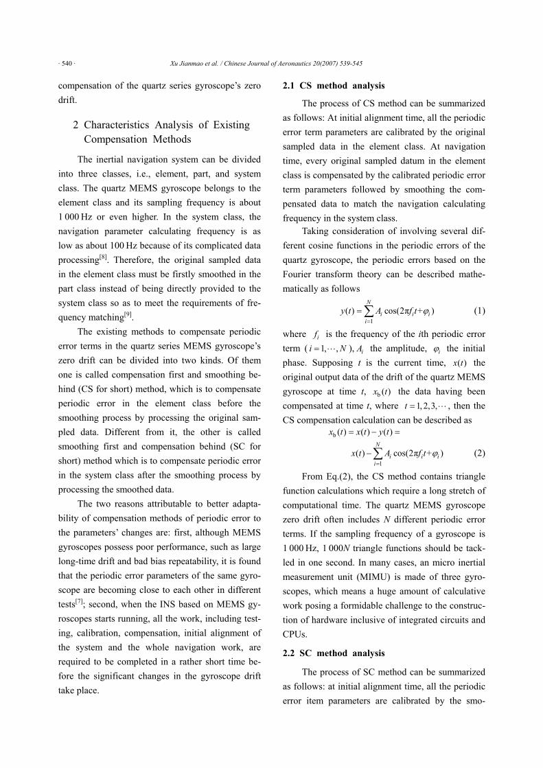
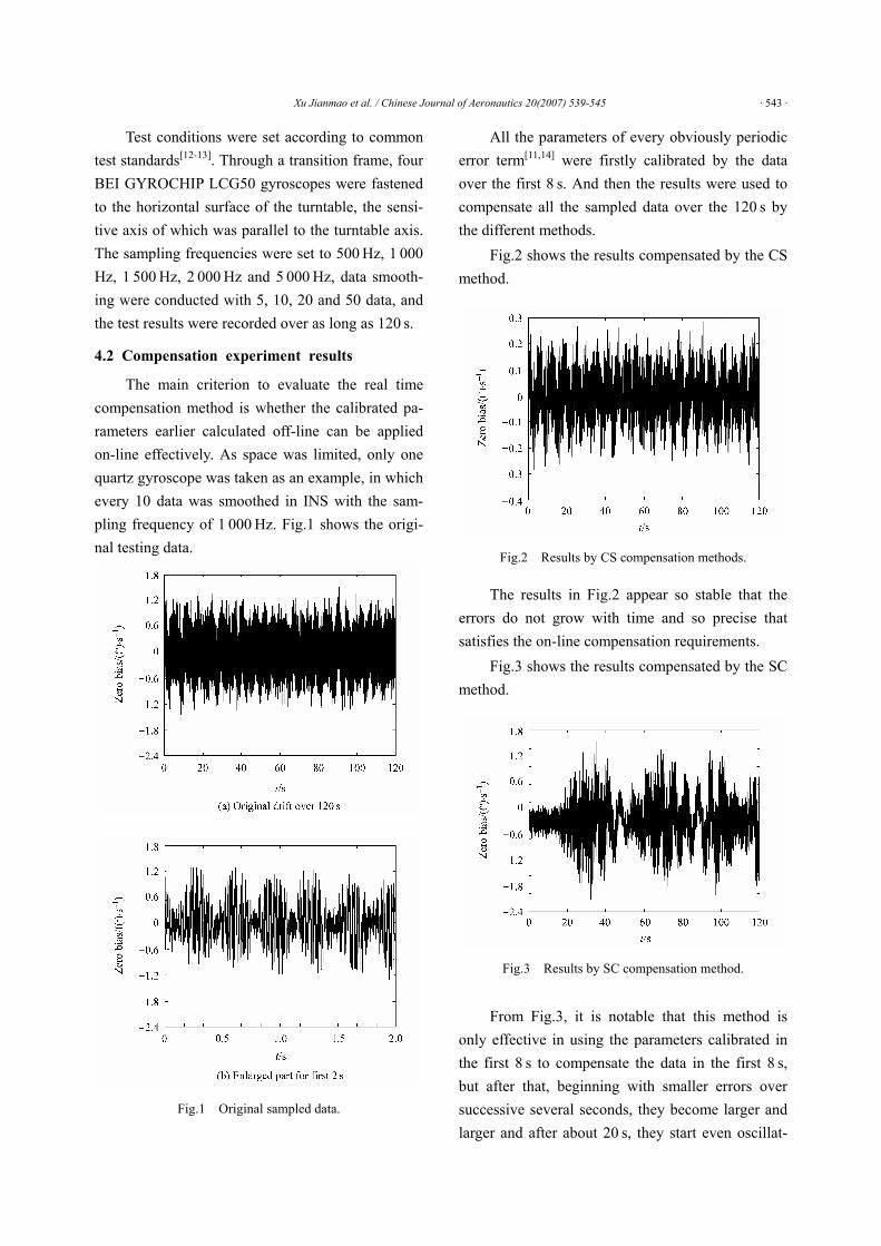
Fig.3 shows the results compensated by the SC method.
Fig.3 Results by SC compensation method.
From Fig.3, it is notable that this method is only effective in using the parameters calibrated in the first 8 s to compensate the data in the first 8 s,but after that, beginning with smaller errors over successive several seconds, they become larger and larger and after about 20 s, they start even oscillat-
· 544 · Xu Jianmao et al. / Chinese Journal of Aeronautics 20(2007) 539-545
ing-diverging with peaks so high as to surpass the highest data before processing.
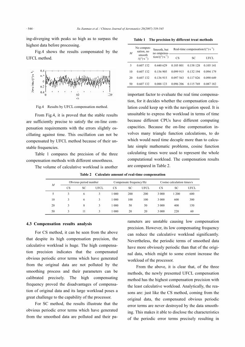
Fig.4 shows the results compensated by the UFCL method.
Fig.4 Results by UFCL compensation method.
From Fig.4, it is proved that the stable results are sufficiently precise to satisfy the on-line com-pensation requirements with the errors slightly os-cillating against time. This oscillation can not be compensated by UFCL method because of their un-stable frequencies.
Table 1 compares the precision of the three compensation methods with different smoothness.
The volume of calculative workload is another
Table 1 The precision by different treat methods
Real-time compensation/((°)·s 1)M
No compen-sation, no smooth /((°)·s 1)
Smooth, but no ompensa-tion/((°)·s 1) CS SC UFCL
5 0.607 132 0.440 629 0.105 801 0.158 128 0.105 141
10 0.607 132 0.156 905 0.099 915 0.132 194 0.094 179
20 0.607 132 0.136 915 0.097 563 0.117 826 0.090 649
50 0.607 132 0.088 123 0.096 206 0.115 769 0.087 182
important factor to evaluate the real time compensa-tion, for it decides whether the compensation calcu-lation could keep up with the navigation speed. It is unsuitable to express the workload in terms of time because different CPUs have different computing capacities. Because the on-line compensation in-volves many triangle function calculations, to do which would need time decuple more than to calcu-late simple mathematic problems, cosine function calculating times were used to represent the whole computational workload. The compensation results are compared in Table 2.
Table 2 Calculate amount of real-time compensation
4.3 Compensation results analysis
For CS method, it can be seen from the above that despite its high compensation precision, the calculative workload is huge. The high compensa-tion precision indicates that the compensated obvious periodic error terms which have generated from the original data are not polluted by the smoothing process and their parameters can be calibrated precisely. The high compensating frequency proved the disadvantages of compensa-tion of original data and its large workload poses a great challenge to the capability of the processor.
For SC method, the results illustrate that the obvious periodic error terms which have generated from the smoothed data are polluted and their pa-
rameters are unstable causing low compensation precision. However, its low compensating frequency can reduce the calculative workload significantly. Nevertheless, the periodic terms of smoothed data have more obviously periodic than that of the origi-nal data, which might to some extent increase the workload of the processor.
From the above, it is clear that, of the three methods, the newly presented UFCL compensation method has the highest compensation precision with the least calculative workload. Analytically, the rea-sons are: just like the CS method, coming from the original data, the compensated obvious periodic error terms are never destroyed by the data smooth-ing. This makes it able to disclose the characteristics of the periodic error terms precisely resulting in
Obvious period number Compensate frequency/Hz Cosine calculation times/sM
CS SC UFCL CS SC UFCL CS SC UFCL
5 3 6 3 1 000 200 200 3 000 1 200 600
10 3 6 3 1 000 100 100 3 000 600 300
20 3 8 3 1 000 50 50 3 000 400 150
50 3 11 3 1 000 20 20 3 000 220 60
Xu Jianmao et al. / Chinese Journal of Aeronautics 20(2007) 539-545 · 545 ·
high compensation precision. Moreover, like the SC method, the compensation of this method is carried out in the system class and its compensation items are the same as the original data thus minimizing the computational workload.
5 Conclusions
The characteristics of existing real-time com-pensation methods of quartz gyroscope drift are re-viewed and the relationship between the periodic error terms in original sampled data and those in smoothed data is studied. On the base of the analy-sis, a new compensation method, UFCL, is pro-posed. Both theoretical analysis and experimental results demonstrate that the UFCL method has higher compensation precision with a decreased computational workload. It stands to reason that as a good solution to meet both compensation precision requirements and real-time requirements of the pe-riodic error terms in quartz series MEMS gyroscope zero drift, this method has a bright future in practi-cal application.
References
[1] Nagel D J. MEMS: micro technology. IEEE Circuits & Device
2001; 17(2):14-25.
[2] Bernstein J. An overview of MEMS inertial sensing technology.
Sensors 2003; 2:48-56.
[3] Knowles S J. Inertial rate sensor tuning fork. United States Parent,
No.6262520, 2001.
[4] Liao X C. Study of micro-quartz tuning-fork gyroscope. PhD
thesis, Beijing Institute of Technology, 2004:2-7. [in Chinese]
[5] Tan Y F. American finite ballistic trajectory guided missile defence
status.http://home.cetin.net.cn/storage/cetin2/report/tmd/tmdzl/zb-
9.htm, 2006. [in Chinese]
[6] Zhang S Y, An B H. New assume of naval vessel weapon sys-
tem—new naval vessel missile system. http://home.cetin.net.cn/
storage/cetin2/pl/pl1/zb-68.htm, 2006. [in Chinese]
[7] Zhang H P, Fang J C. Short time drift study of MEMS gyroscope.
Journal of Chinese Inertial Technology 2007; 15(1):101-104. [in
Chinese]
[8] Ding H G. Proceedings of inertial technology. Beijing: National
Defence Industry Press, 1994:10-29.
[9] He J, Huang X L, Li X F. Study on SINS guidance instrument
error compensation. Acta Aeronautics et Astronautic Sinica 2007;
28(1):182-186. [in Chinese]
[10] Zhang H P, Fang J C, Sheng W. Calibration and compensation the
periodic error in quartz MEMS gyroscope drift. Journal of Beijing
University of Aeronautics and Astronautics (in press). [in Chinese]
[11] Zhang H P, Fang J C. Test and measurement of periodic error in
quartz MEMS vibrant gyroscope zero drift. In: Wen T D editor.
7th International Symposium on Test and Measurement. Beijing:
International Science Press (in press).
[12] Standard specification format guide and test procedure for sin-
gle-axis laser gyros. IEEE Std 647-1995, 1995.
[13] Test procedure for optical fiber gyros. China National Army Stan-
dards, GJB 2426-95, 1995. [in Chinese]
[14] Hu G S. Digital signal processing theory, algorithms and realiza-
tion. Beijing: Tsinghua University Press, 2003. [in Chinese]
Biographies:Xu Jianmao Born in 1965, he earned
the doctorate from Huazhong University
of Science and Technology. His main re-
search interest lies in power machinery
and engineering. E-mail: [email protected]
Zhang Haipeng Born in 1977, he earned
the doctorate from Beijing University of
Aeronautics and Astronautics. His main
research interest lies in micro guidance,
navigation and control system based on
MEMS technology. E-mail: [email protected]