Embed Size (px)
Citation preview
Surgical Technique
Biomet® Peritrochanteric Nail (PTN) System
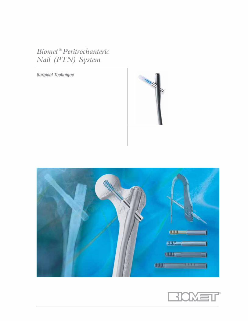
Contents
Introduction .................................................... Page 1
Indications and Contraindications ................... Page 2
OTA Femoral Fracture Classifications .............. Page 3
Surgical Technique ........................................ Page 4
Patient Positioning .................................... Page 4
Draping ..................................................... Page 5
Skin Incision ............................................. Page 5
Entry Point ................................................ Page 6
Determination Of Nail Length .................... Page 7
Canal Reaming .......................................... Page 8
Assembly Of Radiolucent
Targeting Driver ........................................ Page 9
Alignment Check ....................................... Page 9
PTN Insertion ............................................ Page 10
Lag Screw Insertion .................................. Page 11
Lag Screw Fixation.................................... Page 16
Distal Screw Locking
Of The Extra Short And Short PTN ............. Page 18
Free Hand Distal Screw
Locking Of The Long PTN ......................... Page 19
End Cap Insertion ...................................... Page 19
Extraction .................................................. Page 19
Product Information ........................................ Page 20
Further Information ......................................... Page 23
1
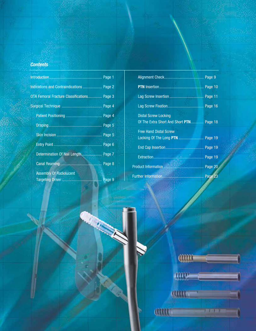
Introduction
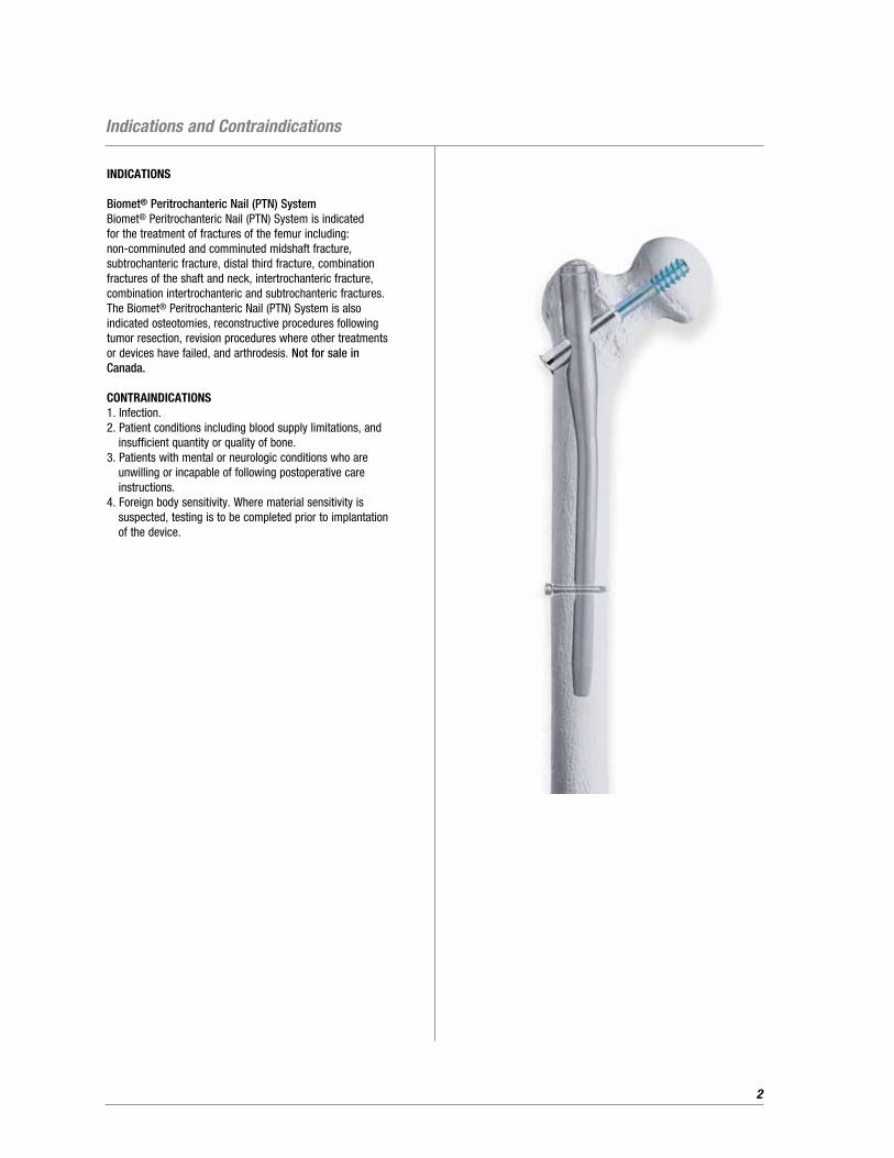
The Biomet Peritrochanteric Nail (PTN) consists of an
intramedullary nail and lag screw indicated for a variety of hip
fractures. Its primary features include the following:
• Setscrew pre-assembled within nail
• Two Telescoping lag screw options (keyed and keyless)
• Two Solid lag screw options (fixed and sliding)
• Small proximal outer diameter (15.9mm)
• 6° proximal bend
• Closer match to anatomic bow of femur (long nail) – 1.8 meter radius anterior bow
• Built-in anteversion (long nail)
• Full range of nail sizing in long (Left and Right), short and extra short (universal) lengths
• Long IM Nails: lengths ranging from 24 – 48cm in 2cm increments, 1.8 meter anterior bow with built-in anteversion and two distal holes (11mm distal outer diameter)
• Short IM Nails: 22cm in overall length with one distal locking hole (11mm and 13mm distal outer diameter)
• Extra Short: 17cm in overall length with one distal locking hole (11mm and 13mm distal outer diameter)
• Telescoping Lag Screws: 11mm keyed and keyless ranging from 65 – 120mm in 5.0mm increments
• Solid Lag Screws: 11mm sliding and fixed ranging from 65 – 120mm in 5.0mm increments
Telescoping lag screws are indicated for intertrochanteric
fractures in which fracture collapse is expected, while preventing
lag screw protrusion into the lateral thigh.
Sliding solid lag screws allow for fracture collapse
and are similar to 1st and 2nd generation trochanteric
nailing systems.
Fixed solid lag screws will prevent any slide or fracture collapse.
Indications are for reverse obliquity/subtrochanteric fractures and
intertrochanteric fractures in younger individuals where fracture
collapse or shortening is to be prevented.
All implantable materials are composed of titanium alloy
(Ti 6AL 4V) for its lightweight strength and concomitant
low modulus of elasticity.
2
INDICATIONS
Biomet® Peritrochanteric Nail (PTN) SystemBiomet® Peritrochanteric Nail (PTN) System is indicated for the treatment of fractures of the femur including: non-comminuted and comminuted midshaft fracture, subtrochanteric fracture, distal third fracture, combination fractures of the shaft and neck, intertrochanteric fracture, combination intertrochanteric and subtrochanteric fractures. The Biomet® Peritrochanteric Nail (PTN) System is also indicated osteotomies, reconstructive procedures following tumor resection, revision procedures where other treatments or devices have failed, and arthrodesis. Not for sale in Canada.
CONTRAINDICATIONS1. Infection.2. Patient conditions including blood supply limitations, and
insufficient quantity or quality of bone.3. Patients with mental or neurologic conditions who are
unwilling or incapable of following postoperative care instructions.
4. Foreign body sensitivity. Where material sensitivity is suspected, testing is to be completed prior to implantation of the device.
Indications and Contraindications
3
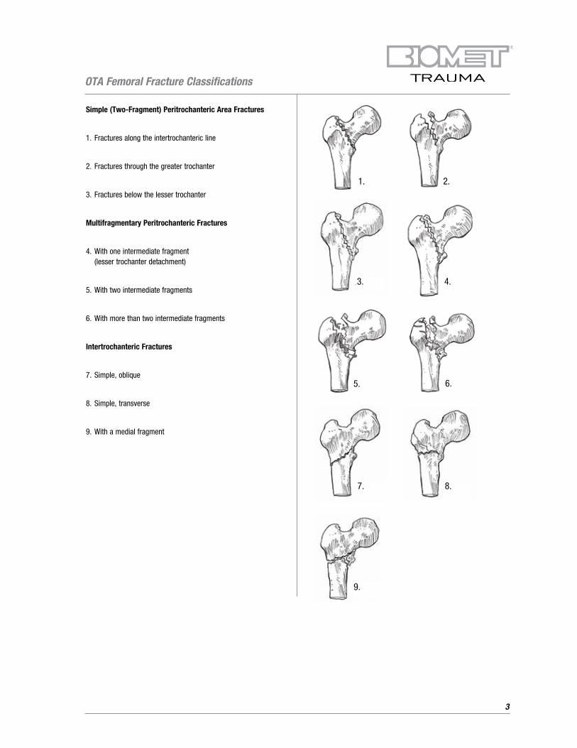
Simple (Two-Fragment) Peritrochanteric Area Fractures
1. Fractures along the intertrochanteric line
2. Fractures through the greater trochanter
3. Fractures below the lesser trochanter
Multifragmentary Peritrochanteric Fractures
4. With one intermediate fragment (lesser trochanter detachment)
5. With two intermediate fragments
6. With more than two intermediate fragments
Intertrochanteric Fractures
7. Simple, oblique
8. Simple, transverse
9. With a medial fragment
OTA Femoral Fracture Classifications
1. 2.
3. 4.
5. 6.
7. 8.
9.
4
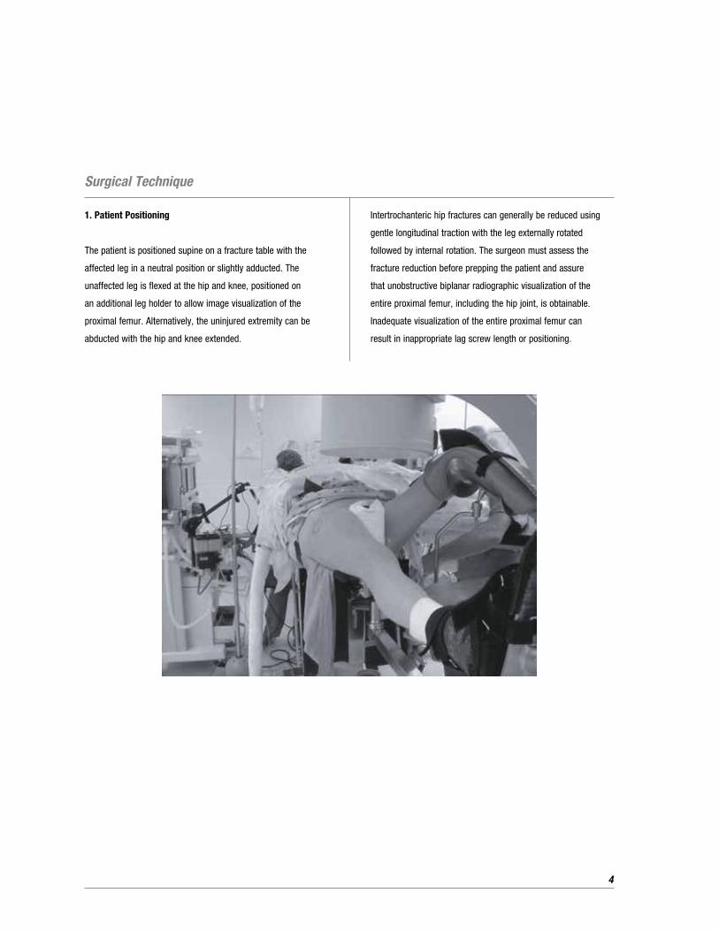
1. Patient Positioning
The patient is positioned supine on a fracture table with the
affected leg in a neutral position or slightly adducted. The
unaffected leg is flexed at the hip and knee, positioned on
an additional leg holder to allow image visualization of the
proximal femur. Alternatively, the uninjured extremity can be
abducted with the hip and knee extended.
Intertrochanteric hip fractures can generally be reduced using
gentle longitudinal traction with the leg externally rotated
followed by internal rotation. The surgeon must assess the
fracture reduction before prepping the patient and assure
that unobstructive biplanar radiographic visualization of the
entire proximal femur, including the hip joint, is obtainable.
Inadequate visualization of the entire proximal femur can
result in inappropriate lag screw length or positioning.
Surgical Technique
5
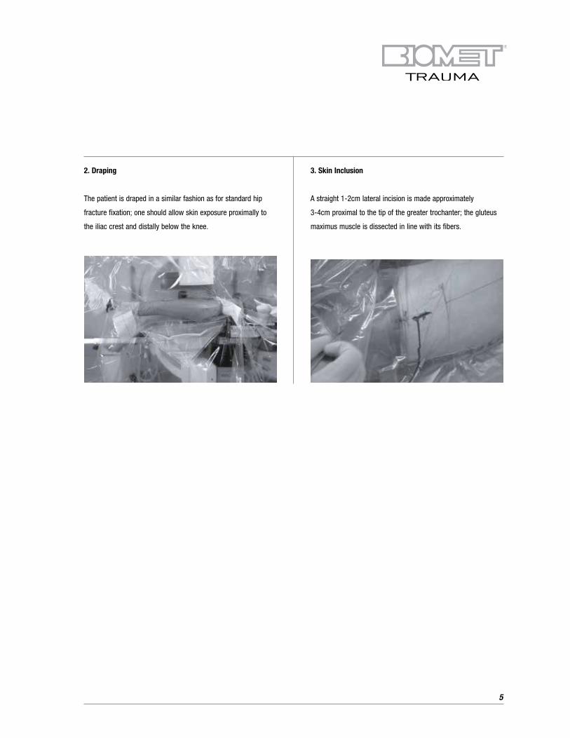
2. Draping
The patient is draped in a similar fashion as for standard hip
fracture fixation; one should allow skin exposure proximally to
the iliac crest and distally below the knee.
3. Skin Inclusion
A straight 1-2cm lateral incision is made approximately
3-4cm proximal to the tip of the greater trochanter; the gluteus
maximus muscle is dissected in line with its fibers.
6
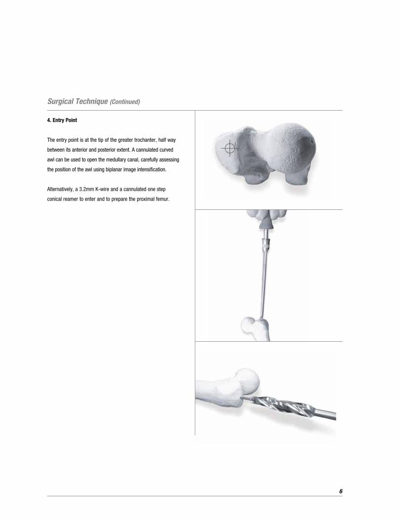
4. Entry Point
The entry point is at the tip of the greater trochanter, half way
between its anterior and posterior extent. A cannulated curved
awl can be used to open the medullary canal, carefully assessing
the position of the awl using biplanar image intensification.
Alternatively, a 3.2mm K-wire and a cannulated one step
conical reamer to enter and to prepare the proximal femur.
Surgical Technique (Continued)
7
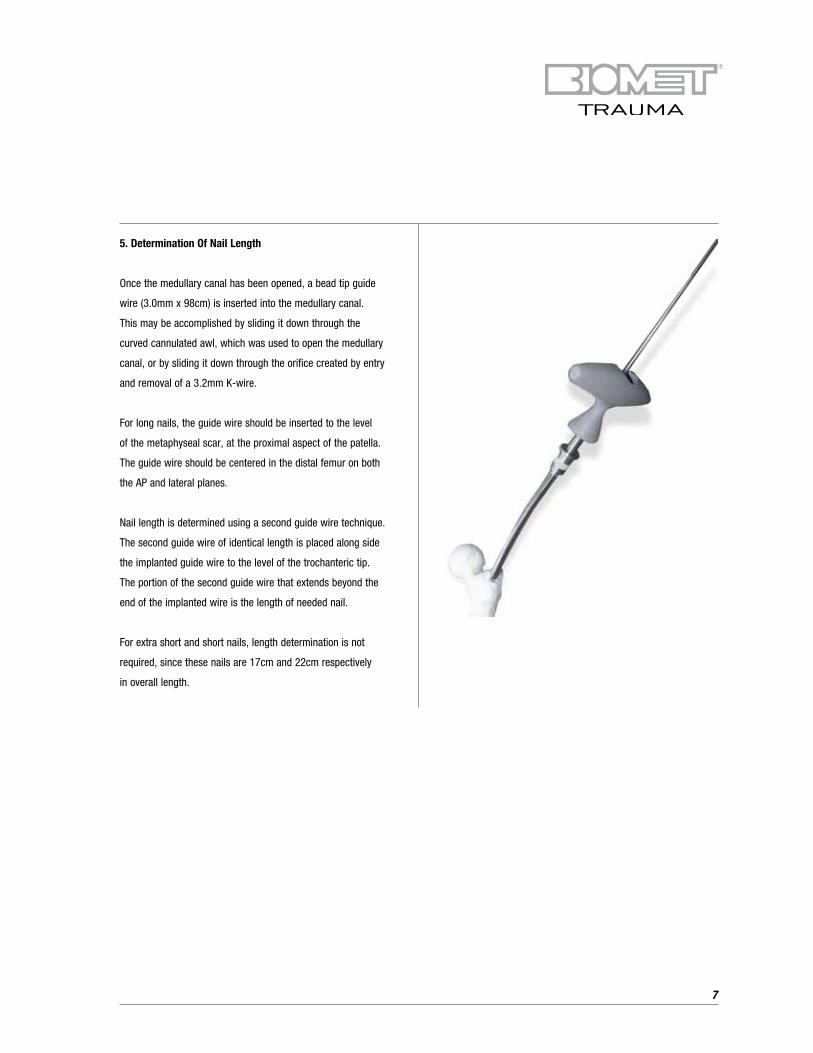
5. Determination Of Nail Length
Once the medullary canal has been opened, a bead tip guide
wire (3.0mm x 98cm) is inserted into the medullary canal.
This may be accomplished by sliding it down through the
curved cannulated awl, which was used to open the medullary
canal, or by sliding it down through the orifice created by entry
and removal of a 3.2mm K-wire.
For long nails, the guide wire should be inserted to the level
of the metaphyseal scar, at the proximal aspect of the patella.
The guide wire should be centered in the distal femur on both
the AP and lateral planes.
Nail length is determined using a second guide wire technique.
The second guide wire of identical length is placed along side
the implanted guide wire to the level of the trochanteric tip.
The portion of the second guide wire that extends beyond the
end of the implanted wire is the length of needed nail.
For extra short and short nails, length determination is not
required, since these nails are 17cm and 22cm respectively
in overall length.
8
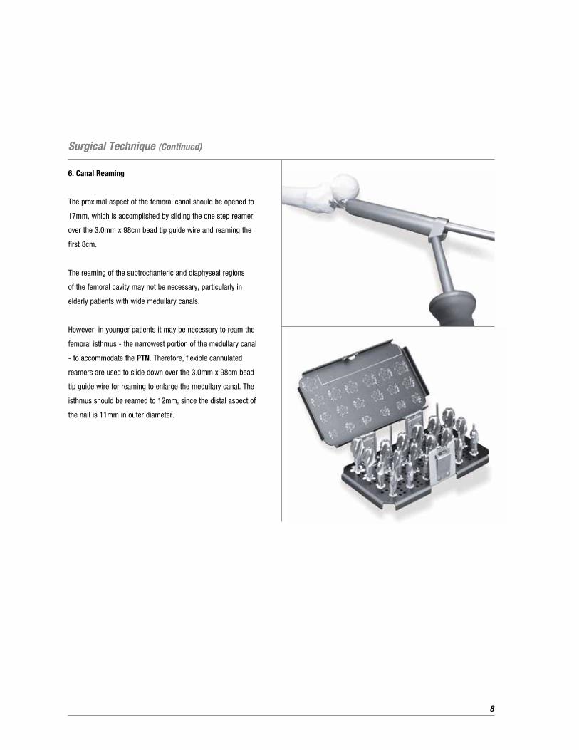
6. Canal Reaming
The proximal aspect of the femoral canal should be opened to
17mm, which is accomplished by sliding the one step reamer
over the 3.0mm x 98cm bead tip guide wire and reaming the
first 8cm.
The reaming of the subtrochanteric and diaphyseal regions
of the femoral cavity may not be necessary, particularly in
elderly patients with wide medullary canals.
However, in younger patients it may be necessary to ream the
femoral isthmus - the narrowest portion of the medullary canal
- to accommodate the PTN. Therefore, flexible cannulated
reamers are used to slide down over the 3.0mm x 98cm bead
tip guide wire for reaming to enlarge the medullary canal. The
isthmus should be reamed to 12mm, since the distal aspect of
the nail is 11mm in outer diameter.
Surgical Technique (Continued)
9
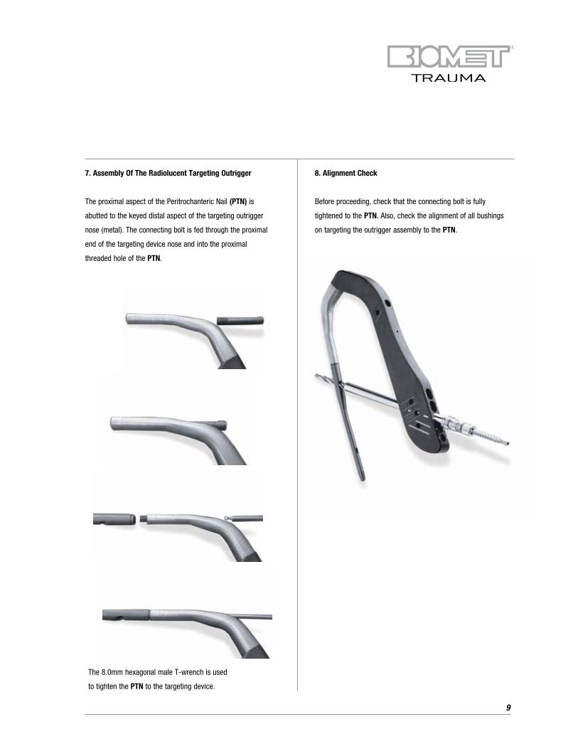
8. Alignment Check
Before proceeding, check that the connecting bolt is fully
tightened to the PTN. Also, check the alignment of all bushings
on targeting the outrigger assembly to the PTN.
The 8.0mm hexagonal male T-wrench is used
to tighten the PTN to the targeting device.
7. Assembly Of The Radiolucent Targeting Outrigger
The proximal aspect of the Peritrochanteric Nail (PTN) is
abutted to the keyed distal aspect of the targeting outrigger
nose (metal). The connecting bolt is fed through the proximal
end of the targeting device nose and into the proximal
threaded hole of the PTN.
10
Surgical Technique (Continued)
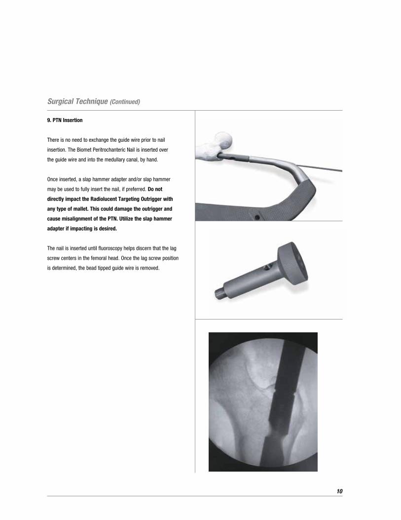
9. PTN Insertion
There is no need to exchange the guide wire prior to nail
insertion. The Biomet Peritrochanteric Nail is inserted over
the guide wire and into the medullary canal, by hand.
Once inserted, a slap hammer adapter and/or slap hammer
may be used to fully insert the nail, if preferred. Do not
directly impact the Radiolucent Targeting Outrigger with
any type of mallet. This could damage the outrigger and
cause misalignment of the PTN. Utilize the slap hammer
adapter if impacting is desired.
The nail is inserted until fluoroscopy helps discern that the lag
screw centers in the femoral head. Once the lag screw position
is determined, the bead tipped guide wire is removed.
11
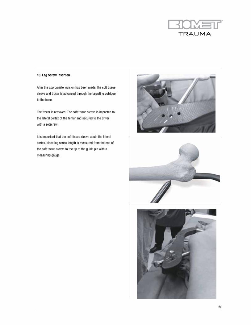
10. Lag Screw Insertion
After the appropriate incision has been made, the soft tissue
sleeve and trocar is advanced through the targeting outrigger
to the bone.
The trocar is removed. The soft tissue sleeve is impacted to
the lateral cortex of the femur and secured to the driver
with a setscrew.
It is important that the soft tissue sleeve abuts the lateral
cortex, since lag screw length is measured from the end of
the soft tissue sleeve to the tip of the guide pin with a
measuring gauge.
12
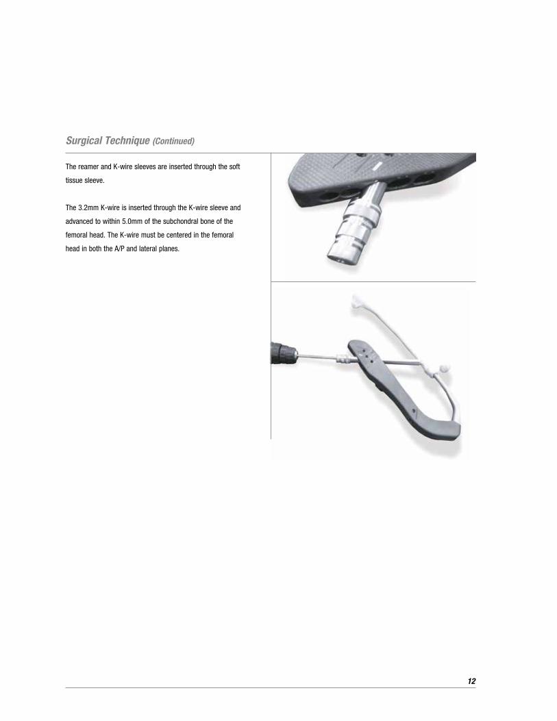
The reamer and K-wire sleeves are inserted through the soft
tissue sleeve.
The 3.2mm K-wire is inserted through the K-wire sleeve and
advanced to within 5.0mm of the subchondral bone of the
femoral head. The K-wire must be centered in the femoral
head in both the A/P and lateral planes.
Surgical Technique (Continued)
13
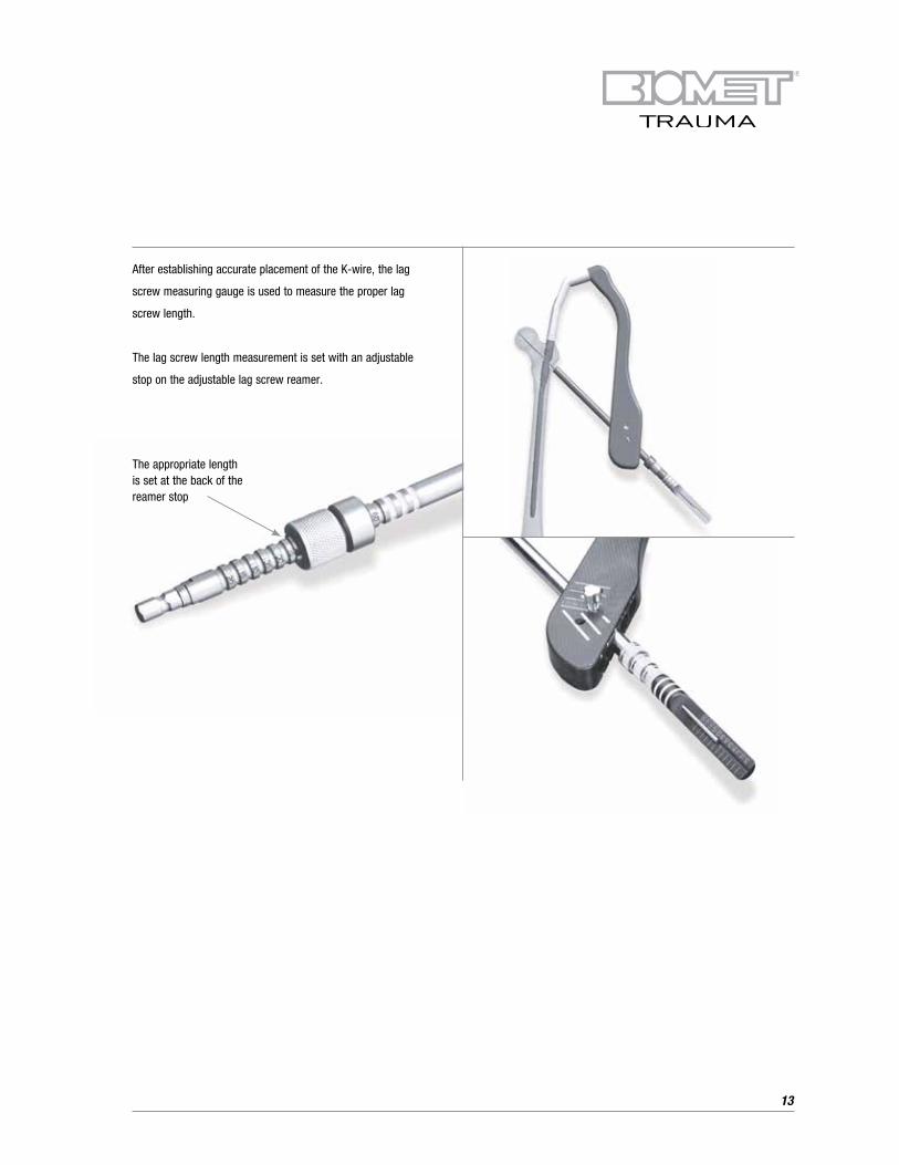
After establishing accurate placement of the K-wire, the lag
screw measuring gauge is used to measure the proper lag
screw length.
The lag screw length measurement is set with an adjustable
stop on the adjustable lag screw reamer.
The appropriate length is set at the back of the reamer stop
14
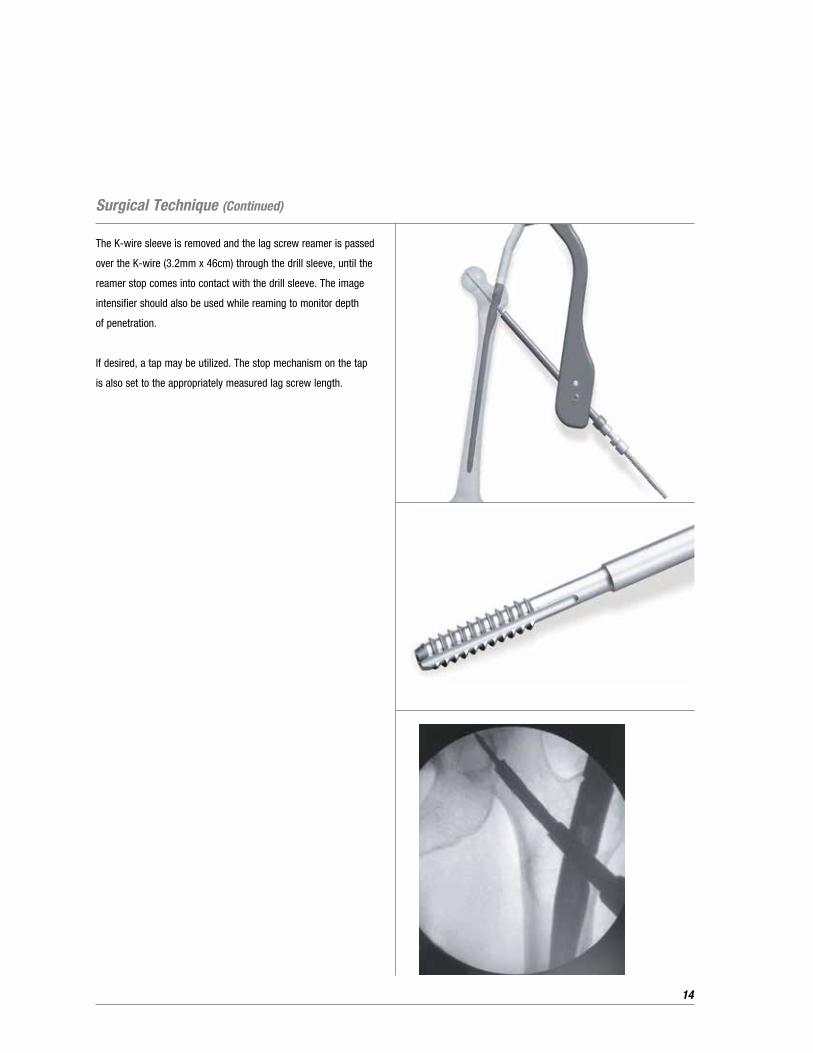
The K-wire sleeve is removed and the lag screw reamer is passed
over the K-wire (3.2mm x 46cm) through the drill sleeve, until the
reamer stop comes into contact with the drill sleeve. The image
intensifier should also be used while reaming to monitor depth
of penetration.
If desired, a tap may be utilized. The stop mechanism on the tap
is also set to the appropriately measured lag screw length.
Surgical Technique (Continued)
15
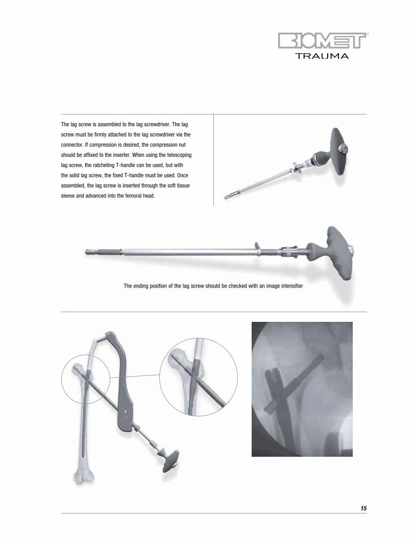
The lag screw is assembled to the lag screwdriver. The lag
screw must be firmly attached to the lag screwdriver via the
connector. If compression is desired, the compression nut
should be affixed to the inserter. When using the telescoping
lag screw, the ratcheting T-handle can be used, but with
the solid lag screw, the fixed T-handle must be used. Once
assembled, the lag screw is inserted through the soft tissue
sleeve and advanced into the femoral head.
The ending position of the lag screw should be checked with an image intensifier
16
Using the lag screw insertion/compression nut yields optimal
compression capability. The lag screw type and length chosen
should be reduced in size depending on the required amount
of compression. Compression of neck/intertrochanteric fracture
site is achieved by using a shorter lag screw and continuing to
advance the threads, after the lip on the telescoping lag screw
has been seated against the lateral cortex.
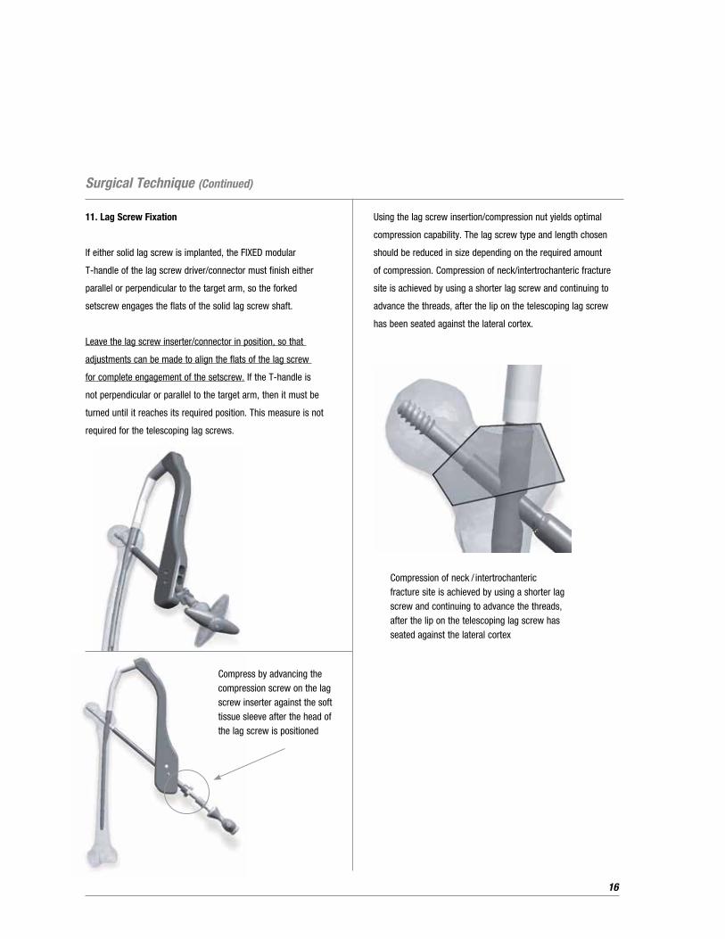
11. Lag Screw Fixation
If either solid lag screw is implanted, the FIXED modular
T-handle of the lag screw driver/connector must finish either
parallel or perpendicular to the target arm, so the forked
setscrew engages the flats of the solid lag screw shaft.
Leave the lag screw inserter/connector in position, so that
adjustments can be made to align the flats of the lag screw
for complete engagement of the setscrew. If the T-handle is
not perpendicular or parallel to the target arm, then it must be
turned until it reaches its required position. This measure is not
required for the telescoping lag screws.
Compress by advancing the compression screw on the lag screw inserter against the soft tissue sleeve after the head of the lag screw is positioned
Compression of neck / intertrochanteric fracture site is achieved by using a shorter lag screw and continuing to advance the threads, after the lip on the telescoping lag screw has seated against the lateral cortex
Surgical Technique (Continued)
17
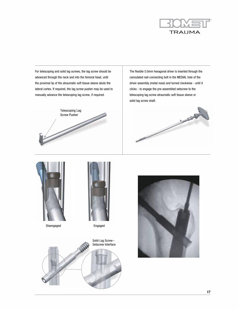
For telescoping and solid lag screws, the lag screw should be
advanced through the neck and into the femoral head, until
the proximal lip of the atraumatic soft tissue sleeve abuts the
lateral cortex. If required, the lag screw pusher may be used to
manually advance the telescoping lag screw, if required.
The flexible 5.0mm hexagonal driver is inserted through the
cannulated nail-connecting bolt in the MEDIAL hole of the
driver assembly (metal nose) and turned clockwise - until it
clicks - to engage the pre-assembled setscrew to the
telescoping lag screw atraumatic soft tissue sleeve or
solid lag screw shaft.
Solid Lag Screw– Setscrew Interface
Telescoping Lag Screw Pusher
Disengaged Engaged
18
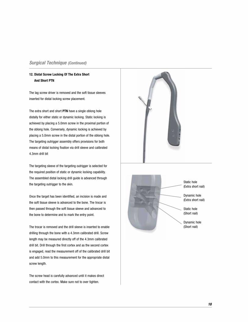
12. Distal Screw Locking Of The Extra Short
And Short PTN
The lag screw driver is removed and the soft tissue sleeves
inserted for distal locking screw placement.
The extra short and short PTN have a single oblong hole
distally for either static or dynamic locking. Static locking is
achieved by placing a 5.0mm screw in the proximal portion of
the oblong hole. Conversely, dynamic locking is achieved by
placing a 5.0mm screw in the distal portion of the oblong hole.
The targeting outrigger assembly offers provisions for both
means of distal locking fixation via drill sleeve and calibrated
4.3mm drill bit
The targeting sleeve of the targeting outrigger is selected for
the required position of static or dynamic locking capability.
The assembled distal locking drill guide is advanced through
the targeting outrigger to the skin.
Once the target has been identified, an incision is made and
the soft tissue sleeve is advanced to the bone. The trocar is
then passed through the soft tissue sleeve and advanced to
the bone to determine and to mark the entry point.
The trocar is removed and the drill sleeve is inserted to enable
drilling through the bone with a 4.3mm calibrated drill. Screw
length may be measured directly off of the 4.3mm calibrated
drill bit. Drill through the first cortex and as the second cortex
is engaged, read the measurement off of the calibrated drill bit
and add 5.0mm to this measurement for the appropriate distal
screw length.
The screw head is carefully advanced until it makes direct
contact with the cortex. Make sure not to over tighten.
Static hole(Extra short nail)
Dynamic hole(Extra short nail)
Static hole (Short nail)
Dynamic hole (Short nail)
Surgical Technique (Continued)
19
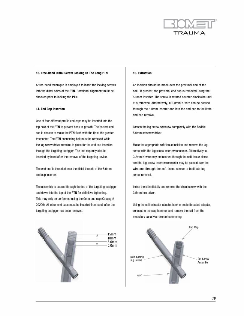
End Cap
15mm10mm5.0mm0.0mm
Nail
Set Screw Assembly
Solid Sliding Lag Screw
13. Free-Hand Distal Screw Locking Of The Long PTN
A free-hand technique is employed to insert the locking screws
into the distal holes of the PTN. Rotational alignment must be
checked prior to locking the PTN.
14. End Cap Insertion
One of four different profile end caps may be inserted into the
top hole of the PTN to prevent bony in-growth. The correct end
cap is chosen to make the PTN flush with the tip of the greater
trochanter. The PTN connecting bolt must be removed while
the lag screw driver remains in place for the end cap insertion
through the targeting outrigger. The end cap may also be
inserted by hand after the removal of the targeting device.
The end cap is threaded onto the distal threads of the 5.0mm
end cap inserter.
The assembly is passed through the top of the targeting outrigger
and down into the top of the PTN for definitive tightening.
This may only be performed using the 0mm end cap (Catalog #
29206). All other end caps must be inserted free hand, after the
targeting outrigger has been removed.
15. Extraction
An incision should be made over the proximal end of the
nail. If present, the proximal end cap is removed using the
5.0mm inserter. The screw is rotated counter-clockwise until
it is removed. Alternatively, a 2.0mm K-wire can be passed
through the 5.0mm inserter and into the end cap to facilitate
end cap removal.
Loosen the lag screw setscrew completely with the flexible
5.0mm setscrew driver.
Make the appropriate soft tissue incision and remove the lag
screw with the lag screw inserter/connector. Alternatively, a
3.2mm K-wire may be inserted through the soft tissue sleeve
and the lag screw inserter/connector may be passed over the
wire and through the soft tissue sleeve to facilitate lag
screw removal.
Incise the skin distally and remove the distal screw with the
3.5mm hex driver.
Using the nail extractor adapter hook or male threaded adapter,
connect to the slap hammer and remove the nail from the
medullary canal via reverse hammering.

20
Product Information
End Caps
Catalog # Implants
29206 End Cap, 0mm
29207 End Cap, 5mm
29208 End Cap, 10mm
29209 End Cap, 15mm
Lag Screws – Telescoping, Keyless
Catalog # Implants
29212 Lag Screw Assy. Telescoping, Keyless, 65mm
29213 Lag Screw Assy. Telescoping, Keyless, 70mm
29214 Lag Screw Assy. Telescoping, Keyless, 75mm
29215 Lag Screw Assy. Telescoping, Keyless, 80mm
29216 Lag Screw Assy. Telescoping, Keyless, 85mm
29217 Lag Screw Assy. Telescoping, Keyless, 90mm
29218 Lag Screw Assy. Telescoping, Keyless, 95mm
29219 Lag Screw Assy. Telescoping, Keyless, 100mm
29220 Lag Screw Assy. Telescoping, Keyless, 105mm
29221 Lag Screw Assy. Telescoping, Keyless, 110mm
29222 Lag Screw Assy. Telescoping, Keyless, 115mm
29223 Lag Screw Assy. Telescoping, Keyless, 120mm
Lag Screws – Telescoping, Keyed
Catalog # Implants
29232 Lag Screw Assy. Telescoping, Keyed, 65mm
29233 Lag Screw Assy. Telescoping, Keyed, 70mm
29234 Lag Screw Assy. Telescoping, Keyed, 75mm
29235 Lag Screw Assy. Telescoping, Keyed, 80mm
29236 Lag Screw Assy. Telescoping, Keyed, 85mm
29237 Lag Screw Assy. Telescoping, Keyed, 90mm
29238 Lag Screw Assy. Telescoping, Keyed, 95mm
29239 Lag Screw Assy. Telescoping, Keyed, 100mm
29240 Lag Screw Assy. Telescoping, Keyed, 105mm
29241 Lag Screw Assy. Telescoping, Keyed, 110mm
29242 Lag Screw Assy. Telescoping, Keyed, 115mm
29243 Lag Screw Assy. Telescoping, Keyed, 120mm
Lag Screws – Solid, Fixed
Catalog # Implants
29252 Lag Screw Assy. Solid, Fixed, 65mm
29253 Lag Screw Assy. Solid, Fixed, 70mm
29254 Lag Screw Assy. Solid, Fixed, 75mm
29255 Lag Screw Assy. Solid, Fixed, 80mm
29256 Lag Screw Assy. Solid, Fixed, 85mm
29257 Lag Screw Assy. Solid, Fixed, 90mm
29258 Lag Screw Assy. Solid, Fixed, 95mm
29259 Lag Screw Assy. Solid, Fixed, 100mm
29260 Lag Screw Assy. Solid, Fixed, 105mm
29261 Lag Screw Assy. Solid, Fixed, 110mm
29262 Lag Screw Assy. Solid, Fixed, 115mm
29263 Lag Screw Assy. Solid, Fixed, 120mm
Lag Screws – Solid, Sliding
Catalog # Implants
29272 Lag Screw, Solid, Sliding, 65mm
29273 Lag Screw, Solid, Sliding, 70mm
29274 Lag Screw, Solid, Sliding, 75mm
29275 Lag Screw, Solid, Sliding, 80mm
29276 Lag Screw, Solid, Sliding, 85mm
29277 Lag Screw, Solid, Sliding, 90mm
29278 Lag Screw, Solid, Sliding, 95mm
29279 Lag Screw, Solid, Sliding, 100mm
29280 Lag Screw, Solid, Sliding, 105mm
29281 Lag Screw, Solid, Sliding, 110mm
29282 Lag Screw, Solid, Sliding, 115mm
29283 Lag Screw, Solid, Sliding, 120mm
21
PTN, Long, Left
Catalog # Implants
28224 PTN, Long, Left, 11mm x 24cm
28226 PTN, Long, Left, 11mm x 26cm
28228 PTN, Long, Left, 11mm x 28cm
28230 PTN, Long, Left, 11mm x 30cm
28232 PTN, Long, Left, 11mm x 32cm
28234 PTN, Long, Left, 11mm x 34cm
28236 PTN, Long, Left, 11mm x 36cm
28238 PTN, Long, Left, 11mm x 38cm
28240 PTN, Long, Left, 11mm x 40cm
28242 PTN, Long, Left, 11mm x 42cm
28244 PTN, Long, Left, 11mm x 44cm
28246 PTN, Long, Left, 11mm x 46cm
28248 PTN, Long, Left, 11mm x 48cm
PTN, Long, Right
Catalog # Implants
28324 PTN, Long, Right, 11mm x 24cm
28326 PTN, Long, Right, 11mm x 26cm
28328 PTN, Long, Right, 11mm x 28cm
28330 PTN, Long, Right, 11mm x 30cm
28332 PTN, Long, Right, 11mm x 32cm
28334 PTN, Long, Right, 11mm x 34cm
28336 PTN, Long, Right, 11mm x 36cm
28338 PTN, Long, Right, 11mm x 38cm
28340 PTN, Long, Right, 11mm x 40cm
28342 PTN, Long, Right, 11mm x 42cm
28344 PTN, Long, Right, 11mm x 44cm
28346 PTN, Long, Right, 11mm x 46cm
28348 PTN, Long, Right, 11mm x 48cm
PTN, Short, Universal
Catalog # Implants
28811 PTN, Short, 11mm x 22cm
28813 PTN, Short, 13mm x 22cm
PTN, Extra Short, Universal
Catalog # Implants
28821 PTN, Extra Short, 11mm x 17cm
28823 PTN, Extra Short, 13mm x 17cm
Cross Locking Screws
Catalog # Implants
33-345418 5.0mm Hex HD Screw Buttress Full Thread, 20mm
33-345420 5.0mm Hex HD Screw Buttress Full Thread, 25mm
33-345422 5.0mm Hex HD Screw Buttress Full Thread, 30mm
33-345424 5.0mm Hex HD Screw Buttress Full Thread, 35mm
33-345426 5.0mm Hex HD Screw Buttress Full Thread, 40mm
33-345428 5.0mm Hex HD Screw Buttress Full Thread, 45mm
33-345430 5.0mm Hex HD Screw Buttress Full Thread, 50mm
33-345432 5.0mm Hex HD Screw Buttress Full Thread, 55mm
33-345434 5.0mm Hex HD Screw Buttress Full Thread, 60mm
33-345436 5.0mm Hex HD Screw Buttress Full Thread, 65mm
33-345438 5.0mm Hex HD Screw Buttress Full Thread, 70mm
33-345440 5.0mm Hex HD Screw Buttress Full Thread, 75mm
33-345442 5.0mm Hex HD Screw Buttress Full Thread, 80mm
33-345444 5.0mm Hex HD Screw Buttress Full Thread, 85mm
33-345446 5.0mm Hex HD Screw Buttress Full Thread, 90mm
33-345448 5.0mm Hex HD Screw Buttress Full Thread, 95mm
33-345450 5.0mm Hex HD Screw Buttress Full Thread, 100mm
33-345452 5.0mm Hex HD Screw Buttress Full Thread, 105mm
33-345454 5.0mm Hex HD Screw Buttress Full Thread, 110mm
PTN/UniFlex Antegrade
Catalog # Disposable Instruments
27914 Lag Screw / 3.2mm x 46cm Entry Guide Wire
27922 Nail Guide Wire, Bead Tip (3.0mm x 98cm)
27949 Straight Guide Wire, 3.2mm x 98cm
27961 Calibrated Drill - 4.3mm x 36.5cm
27982 Calibrated Drill - 5.0mm x 36.5cm
27983 Calibrated Drill - 6.2mm x 48.2cm
27984 Crowe Pt. Drill Bit - 4.3mm x 18cm
22
Product Information (Continued)
Optional Specialty Instruments (PTN)
Catalog # Instruments
27979 Fracture Reducer
27972 Slap Hammer
475920 X-Ray Scale (Ruler)
27937 Working Channel Soft Tissue Sleeve
27938 Working Channel Soft Tissue Sleeve Trocar
27908 One-Step Reamer, 17mm
27969 Lag Screw Sleeve Pusher
469380 Telescoping Nail Measuring Gauge
03248 Surgical Tray, Specialty Instruments
470342 Diamond Point Awl
476920 Skin Protector
471794 Distal Targeting Awl 4.3mm
471795 Distal Targeting Awl 5.0mm
PTN/UniFlex Antegrade
Catalog # Femoral Nail Instruments
03138 Surgical Tray Femoral Nail System
27902 Driver Connecting Screw
27903 T-Handle w/Stryker Quick Connect (Non-ratcheting)
27904 T-Handle w/Stryker Quick Connect (Ratcheting)
27913 Wire Pusher
27915 Solid Lag Screw Reamer
27916 Lag Screw Measuring Gauge
27918 Sleeve Thumb Screw
27919 Lag Screw Tap
27920 Wire Holder
27923 Torque Limiting Handle, Straight
27924 Reconstructive Soft Tissue Sleeve
27925 Reconstructive Trocar
27926 Reconstructive Drill Bushing
27927 Reconstructive Wire Bushing
27929 Nail Measuring Gauge
27936 Interlocking Drill Bushing
PTN/UniFlex Antegrade (Continued)
Catalog # Femoral Nail Instruments
27939 Flexible Reamer Shaft Extension
27940 Flexible Reamer Shaft
27943 Compression Nut
27947 8.0mm Connecting Bolt Driver
27950 Hybrid Trochanteric Driver
27953 Lag Inserter Inner Shaft Assy.
27954 Guide Tube, Trochanteric Lag Screw
27955 Lag Screw Trocar
27956 Guide Bushing, Trochanteric, 3.2mm Guide Pin
27957 Lag Screw Drill Bushing Std
27962 Flexible Hex Driver, 5.0mm
27964 Guide Tube, Trochanteric
27965 Trocar, Cross Locking Screw
27966 Cross Locking Drill Bushing, 4.3mm
27970 Slap Hammer Adaptor
27977 Stryker/AO Power Adaptor
27989 Hall/Stryker Power Adaptor
27990 Lag Screw Inserter
27992 Screw Holding/Driver Assy. (Distal Screw)
27996 5.0mm Inserter Connector
27997 5.0mm Inserter
27999 Curved Cannulated Awl
467534 Next Modular Reamer Head, 8.0mm
467536 Next Modular Reamer Head, 8.5mm
467538 Next Modular Reamer Head, 9.0mm
467540 Next Modular Reamer Head, 9.5mm
467542 Next Modular Reamer Head, 10mm
467544 Next Modular Reamer Head, 10.5mm
467546 Next Modular Reamer Head, 11mm
467548 Next Modular Reamer Head, 11.5mm
467550 Next Modular Reamer Head, 12mm
467552 Next Modular Reamer Head, 12.5mm
467554 Next Modular Reamer Head, 13mm
23
Further Information
This brochure is presented to demonstrate the surgical
technique utilized by Ken Koval, M.D. Biomet, as the
manufacturer of this device, does not practice medicine and
does not recommend this product or any specific surgical
technique for use on any individual patient. The surgeon who
performs any implant procedure is responsible for determining
the appropriate product(s) and utilizing the appropriate
technique(s) for said implantation in each individual patient.
For further information, please contact the Customer Service
Department at:
Biomet Trauma
56 East Bell Drive
P.O. Box 587
Warsaw, Indiana 46581-0587
800.348.9500 x 1501
www.biomet.com
PTN/UniFlex Antegrade (Continued)
Catalog # Femoral Nail Instruments
467556 Next Modular Reamer Head, 13.5mm
467558 Next Modular Reamer Head, 14mm
467560 Next Modular Reamer Head, 14.5mm
467562 Next Modular Reamer Head, 15mm
467564 Next Modular Reamer Head, 15.5mm
467566 Next Modular Reamer Head, 16mm
467568 Next Modular Reamer Head, 16.5mm
467570 Next Modular Reamer Head, 17mm
471768 Nail Extractor Adaptor
471770 Nail Extractor Hook w/Adaptor
34-513644 Screw Depth Gauge

24
Notes:


©2013 Biomet Orthopedics • Form No. BMET0261.0 • REV011513
All trademarks herein are the property of Biomet, Inc. or its subsidiaries unless otherwise indicated.
This material is intended for the sole use and benefit of the Biomet sales force and health care professionals. It is not to be redistributed, duplicated or disclosed without the express written consent of Biomet.
For product information, including indications, contraindications, warnings, precautions and potential adverse effects, see the package insert and Biomet’s website.
Responsible ManufacturerBiomet, Inc. P.O. Box 58756 E. Bell DriveWarsaw, Indiana 46581-0587 USA
www.biomet.com
Rx only.