Embed Size (px)
Citation preview
Perle PoE/PoE+ 10/100 Ethernet
Media Converters
Installation Guide
S-110-P S-110P-XT
S-110PP S-110PP-XT
S-110P-SFP S-110P-SFP-XT
S-110PP-SFP S-110PP-SFP-XT
Part# 5500318-14 (Rev A)
Perle PoE/PoE+ 10/100 Ethernet Media Converter
2
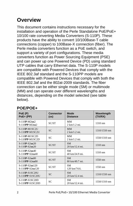
Overview This document contains instructions necessary for the installation and operation of the Perle Standalone PoE/PoE+ 10/100 rate converting Media Converters (S-110P). These products have the ability to convert 10/100Base-T cable connections (copper) to 100Base-X connection (fiber). The Perle media converters function as a PoE switch, and support a variety of port configurations. These media converters function as Power Sourcing Equipment (PSE) and can power up one Powered Device (PD) using standard UTP cables that carry Ethernet data. The S-110P models are compatible with Powered Devices that comply with the IEEE 802.3af standard and the S-110PP models are compatible with Powered Devices that comply with both the IEEE 802.3af and the 802at-2009 standards. The fiber connection can be either single mode (SM) or multimode (MM) and can operate over different wavelengths and distances, depending on the model selected (see table below).
POE/POE+ PoE (P) PoE+ (PP)
Connector (xx)
Mode Distance
Wavelength (TX/RX)
S-110P-M2xx2 S-110PP-M2xx2
SC/ST MM 2 km/1.2 mi.
1310 nm
S-110P-M1SC2U S-110PP-M1SC2U
SC MM 2 km/1.2 mi.
1310/1550 nm
S-110P-M1SC2D S-110PP-M1SC2D
SC MM 2 km/1.2 mi.
1550/1310 nm
S-110P-S2xx20 S-110P-S2xx20
SC/ST SM 20 km/12.4 mi.
1310 nm
S-110P-S2xx40 S-110PP-S2xx40
SC/ST SM 40 km/24.9 mi.
1310 nm
S-110P-S2xx80 S-110PP-S2xx80
SC/ST SM 80 km/49.7 mi.
1550 nm
S-110P-S2xx120 S-110PP-S2xx120
SC/ST SM 120 km/74.6.
1550 nm
S-110P-S1SC20U S-110PP-S1SC20U
SC SM 20 km/12.4 mi.
1310/1550 nm
S-110P-S1SC20D S-110PP-S1SC20D
SC SM 20 km/12.4 mi.
1550/1310 nm
Perle PoE/PoE+ 10/100 Ethernet Media Converter
3
PoE (P) PoE+ (PP)
Connector (xx)
Mode Distance
Wavelength (TX/RX)
S-110P-S1SC40U S-110PP-S1SC40U
SC SM 40 km/24.9 mi.
1510/1590 nm
S-110P-S1SC40D S-110PP-S1SC40D
SC SM 40 km/24.9 mi.
1590/1510 nm
S-110P-SFP S-110PP-SFP
SFP NOTE 1
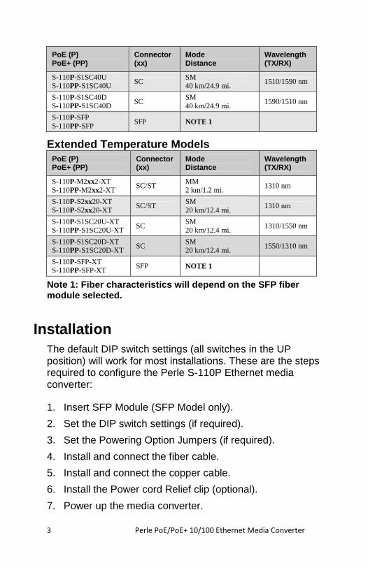
Extended Temperature Models PoE (P) PoE+ (PP)
Connector (xx)
Mode Distance
Wavelength (TX/RX)
S-110P-M2xx2-XT S-110PP-M2xx2-XT
SC/ST MM 2 km/1.2 mi.
1310 nm
S-110P-S2xx20-XT S-110P-S2xx20-XT
SC/ST SM 20 km/12.4 mi.
1310 nm
S-110P-S1SC20U-XT S-110PP-S1SC20U-XT
SC SM 20 km/12.4 mi.
1310/1550 nm
S-110P-S1SC20D-XT S-110PP-S1SC20D-XT
SC SM 20 km/12.4 mi.
1550/1310 nm
S-110P-SFP-XT S-110PP-SFP-XT
SFP NOTE 1
Note 1: Fiber characteristics will depend on the SF P fiber module selected.
Installation
The default DIP switch settings (all switches in the UP position) will work for most installations. These are the steps required to configure the Perle S-110P Ethernet media converter:
1. Insert SFP Module (SFP Model only).
2. Set the DIP switch settings (if required).
3. Set the Powering Option Jumpers (if required).
4. Install and connect the fiber cable.
5. Install and connect the copper cable.
6. Install the Power cord Relief clip (optional).
7. Power up the media converter.
Perle PoE/PoE+ 10/100 Ethernet Media Converter
4
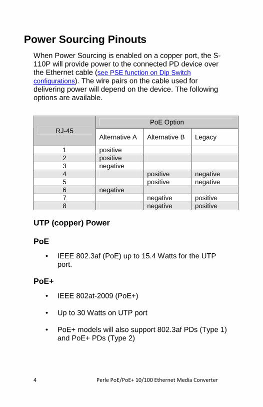
Power Sourcing Pinouts When Power Sourcing is enabled on a copper port, the S-110P will provide power to the connected PD device over the Ethernet cable (see PSE function on Dip Switch configurations). The wire pairs on the cable used for delivering power will depend on the device. The following options are available.
PoE Option RJ-45
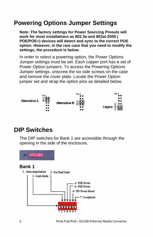
Alternative A Alternative B Legacy
1 positive 2 positive 3 negative 4 positive negative 5 positive negative 6 negative 7 negative positive 8 negative positive
UTP (copper) Power
PoE
• IEEE 802.3af (PoE) up to 15.4 Watts for the UTP port.
PoE+
• IEEE 802at-2009 (PoE+)
• Up to 30 Watts on UTP port
• PoE+ models will also support 802.3af PDs (Type 1) and PoE+ PDs (Type 2)
Perle PoE/PoE+ 10/100 Ethernet Media Converter
5
Powering Options Jumper Settings Note: The factory settings for Power Sourcing Pinou ts will work for most installations as 802.3a and 802at-200 9 ( POE/POE+) devices will detect and sync to the corre ct POE option. However, in the rare case that you need to modify the settings, the procedure is below.
In order to select a powering option, the Power Options Jumper settings must be set. Each copper port has a set of Power Option jumpers. To access the Powering Options Jumper settings, unscrew the six side screws on the case and remove the cover plate. Locate the Power Option jumper set and strap the option pins as detailed below.
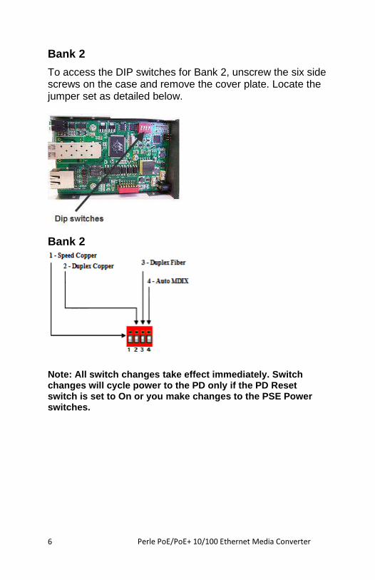
DIP Switches The DIP switches for Bank 1 are accessible through the opening in the side of the enclosure.
Bank 1
Perle PoE/PoE+ 10/100 Ethernet Media Converter
6
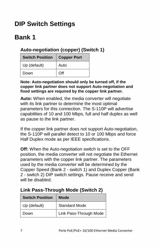
Bank 2
To access the DIP switches for Bank 2, unscrew the six side screws on the case and remove the cover plate. Locate the jumper set as detailed below.
Bank 2
Note: All switch changes take effect immediately. S witch changes will cycle power to the PD only if the PD R eset switch is set to On or you make changes to the PSE Power switches.
Perle PoE/PoE+ 10/100 Ethernet Media Converter
7
DIP Switch Settings
Bank 1
Auto-negotiation (copper) (Switch 1)
Switch Position Copper Port
Up (default) Auto
Down Off
Note: Auto-negotiation should only be turned off, if the copper link partner does not support Auto-negotiati on and fixed settings are required by the copper link part ner.
Auto: When enabled, the media converter will negotiate with its link partner to determine the most optimal parameters for this connection. The S-110P will advertise capabilities of 10 and 100 Mbps, full and half duplex as well as pause to the link partner.
If the copper link partner does not support Auto-negotiation, the S-110P will parallel detect to 10 or 100 Mbps and force Half Duplex mode as per IEEE specifications.
Off: When the Auto-negotiation switch is set to the OFF position, the media converter will not negotiate the Ethernet parameters with the copper link partner. The parameters used by the media converter will be determined by the Copper Speed (Bank 2 - switch 1) and Duplex Copper (Bank 2 - switch 2) DIP switch settings. Pause receive and send will be disabled.
Link Pass-Through Mode (Switch 2)
Switch Position Mode
Up (default) Standard Mode
Down Link Pass-Through Mode
Perle PoE/PoE+ 10/100 Ethernet Media Converter
8
Standard Mode: In this mode, links on the fiber and copper sides can be brought up and down independently of each other. A loss of link on either the fiber or copper port can occur without affecting the other connection.
Link Pass-Through Mode: In this mode, the link state on one connection is directly reflected through the media converter to the other connection. If link is lost on one of the connections, then the other link will be brought down by the media converter.
If the installation has a media converter on both ends of the fiber link and both are set-up for Link Pass-Through, then a loss of copper link on the far end device will propagate through both media converters and will result in a loss of link at the near end device.
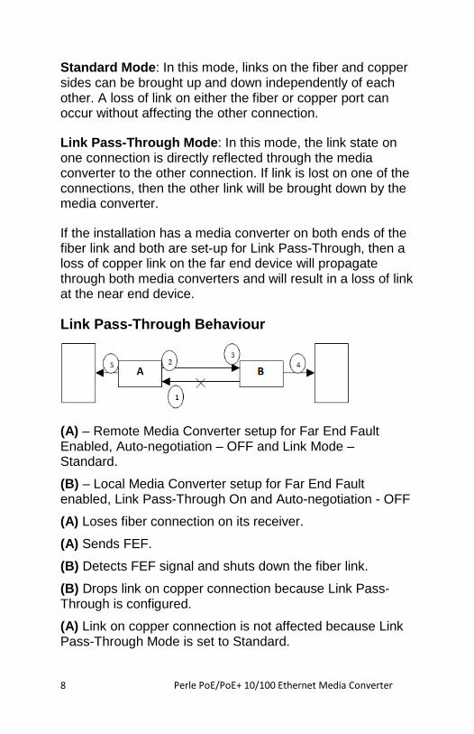
Link Pass-Through Behaviour
(A) – Remote Media Converter setup for Far End Fault Enabled, Auto-negotiation – OFF and Link Mode – Standard.
(B) – Local Media Converter setup for Far End Fault enabled, Link Pass-Through On and Auto-negotiation - OFF
(A) Loses fiber connection on its receiver.
(A) Sends FEF.
(B) Detects FEF signal and shuts down the fiber link.
(B) Drops link on copper connection because Link Pass-Through is configured.
(A) Link on copper connection is not affected because Link Pass-Through Mode is set to Standard.
Perle PoE/PoE+ 10/100 Ethernet Media Converter
9
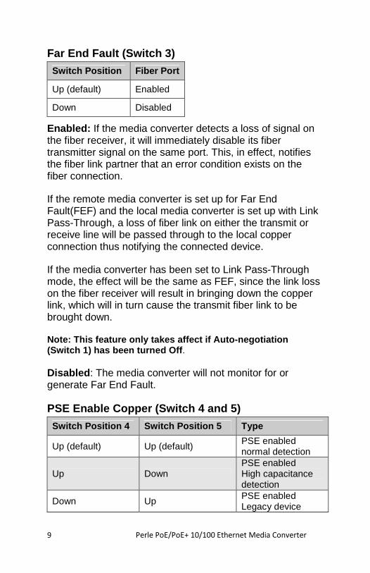
Far End Fault (Switch 3)
Switch Position Fiber Port
Up (default) Enabled
Down Disabled
Enabled: If the media converter detects a loss of signal on the fiber receiver, it will immediately disable its fiber transmitter signal on the same port. This, in effect, notifies the fiber link partner that an error condition exists on the fiber connection.
If the remote media converter is set up for Far End Fault(FEF) and the local media converter is set up with Link Pass-Through, a loss of fiber link on either the transmit or receive line will be passed through to the local copper connection thus notifying the connected device.
If the media converter has been set to Link Pass-Through mode, the effect will be the same as FEF, since the link loss on the fiber receiver will result in bringing down the copper link, which will in turn cause the transmit fiber link to be brought down.
Note: This feature only takes affect if Auto-negoti ation (Switch 1) has been turned Off .
Disabled: The media converter will not monitor for or generate Far End Fault.
PSE Enable Copper (Switch 4 and 5)
Switch Position 4 Switch Position 5 Type
Up (default) Up (default) PSE enabled normal detection
Up Down PSE enabled High capacitance detection
Down Up PSE enabled Legacy device
Perle PoE/PoE+ 10/100 Ethernet Media Converter
10
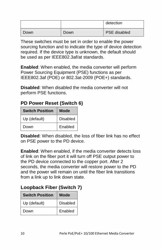
detection
Down Down PSE disabled
These switches must be set in order to enable the power sourcing function and to indicate the type of device detection required. If the device type is unknown, the default should be used as per IEEE802.3af/at standards.
Enabled: When enabled, the media converter will perform Power Sourcing Equipment (PSE) functions as per IEEE802.3af (POE) or 802.3at-2009 (POE+) standards.
Disabled: When disabled the media converter will not perform PSE functions.
PD Power Reset (Switch 6)
Switch Position Mode
Up (default) Disabled
Down Enabled
Disabled: When disabled, the loss of fiber link has no effect on PSE power to the PD device.
Enabled: When enabled, if the media converter detects loss of link on the fiber port it will turn off PSE output power to the PD device connected to the copper port. After 2 seconds, the media converter will restore power to the PD and the power will remain on until the fiber link transitions from a link up to link down state.
Loopback Fiber (Switch 7)
Switch Position Mode
Up (default) Disabled
Down Enabled
Perle PoE/PoE+ 10/100 Ethernet Media Converter
11
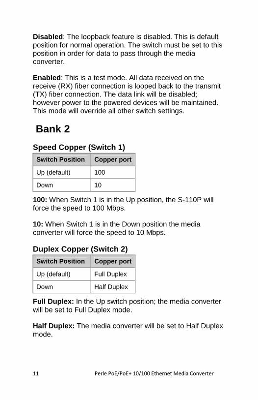
Disabled: The loopback feature is disabled. This is default position for normal operation. The switch must be set to this position in order for data to pass through the media converter.
Enabled: This is a test mode. All data received on the receive (RX) fiber connection is looped back to the transmit (TX) fiber connection. The data link will be disabled; however power to the powered devices will be maintained. This mode will override all other switch settings.
Bank 2
Speed Copper (Switch 1)
Switch Position Copper port
Up (default) 100
Down 10
100: When Switch 1 is in the Up position, the S-110P will force the speed to 100 Mbps.
10: When Switch 1 is in the Down position the media converter will force the speed to 10 Mbps.
Duplex Copper (Switch 2)
Switch Position Copper port
Up (default) Full Duplex
Down Half Duplex
Full Duplex: In the Up switch position; the media converter will be set to Full Duplex mode.
Half Duplex: The media converter will be set to Half Duplex mode.
Perle PoE/PoE+ 10/100 Ethernet Media Converter
12
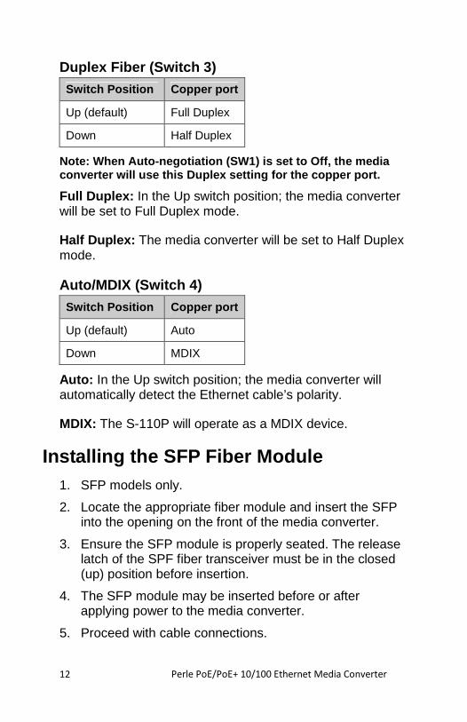
Duplex Fiber (Switch 3)
Switch Position Copper port
Up (default) Full Duplex
Down Half Duplex
Note: When Auto-negotiation (SW1) is set to Off, th e media converter will use this Duplex setting for the copp er port.
Full Duplex: In the Up switch position; the media converter will be set to Full Duplex mode.
Half Duplex: The media converter will be set to Half Duplex mode.
Auto/MDIX (Switch 4)
Switch Position Copper port
Up (default) Auto
Down MDIX
Auto: In the Up switch position; the media converter will automatically detect the Ethernet cable’s polarity.
MDIX: The S-110P will operate as a MDIX device.
Installing the SFP Fiber Module 1. SFP models only.
2. Locate the appropriate fiber module and insert the SFP into the opening on the front of the media converter.
3. Ensure the SFP module is properly seated. The release latch of the SPF fiber transceiver must be in the closed (up) position before insertion.
4. The SFP module may be inserted before or after applying power to the media converter.
5. Proceed with cable connections.
Perle PoE/PoE+ 10/100 Ethernet Media Converter
13
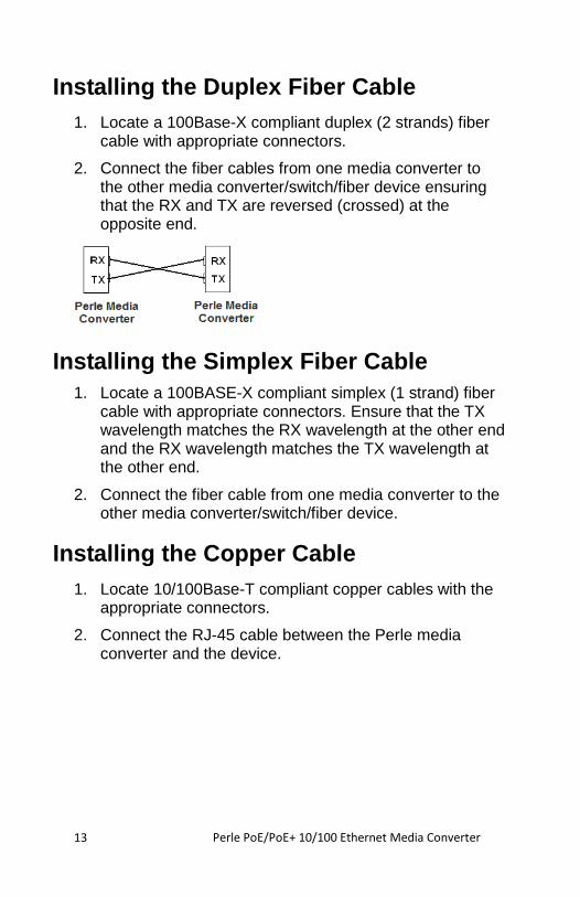
Installing the Duplex Fiber Cable 1. Locate a 100Base-X compliant duplex (2 strands) fiber
cable with appropriate connectors.
2. Connect the fiber cables from one media converter to the other media converter/switch/fiber device ensuring that the RX and TX are reversed (crossed) at the opposite end.
Installing the Simplex Fiber Cable 1. Locate a 100BASE-X compliant simplex (1 strand) fiber
cable with appropriate connectors. Ensure that the TX wavelength matches the RX wavelength at the other end and the RX wavelength matches the TX wavelength at the other end.
2. Connect the fiber cable from one media converter to the other media converter/switch/fiber device.
Installing the Copper Cable 1. Locate 10/100Base-T compliant copper cables with the
appropriate connectors.
2. Connect the RJ-45 cable between the Perle media converter and the device.
Perle PoE/PoE+ 10/100 Ethernet Media Converter
14
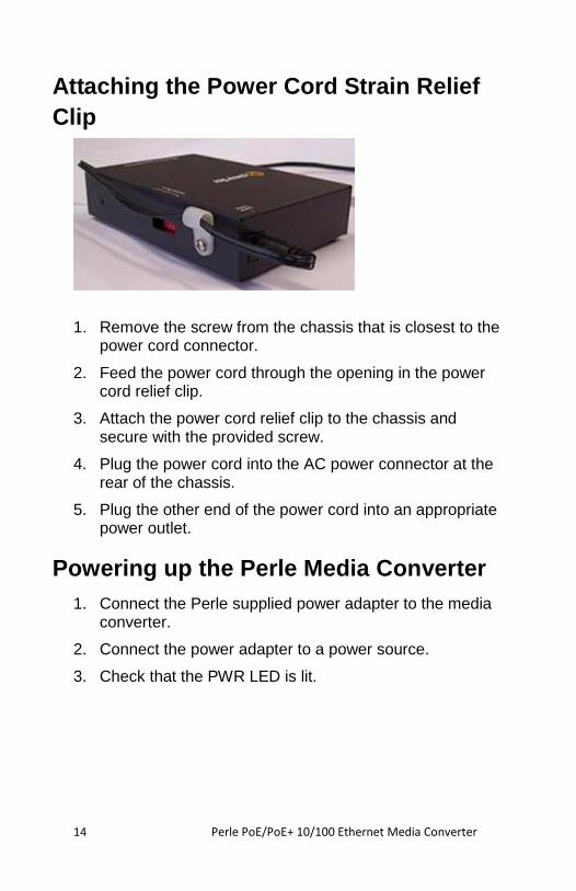
Attaching the Power Cord Strain Relief Clip
1. Remove the screw from the chassis that is closest to the power cord connector.
2. Feed the power cord through the opening in the power cord relief clip.
3. Attach the power cord relief clip to the chassis and secure with the provided screw.
4. Plug the power cord into the AC power connector at the rear of the chassis.
5. Plug the other end of the power cord into an appropriate power outlet.
Powering up the Perle Media Converter 1. Connect the Perle supplied power adapter to the media
converter.
2. Connect the power adapter to a power source.
3. Check that the PWR LED is lit.
Perle PoE/PoE+ 10/100 Ethernet Media Converter
15
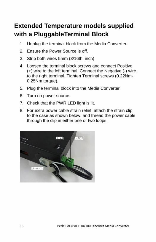
Extended Temperature models supplied with a PluggableTerminal Block
1. Unplug the terminal block from the Media Converter.
2. Ensure the Power Source is off.
3. Strip both wires 5mm (3/16th inch)
4. Loosen the terminal block screws and connect Positive (+) wire to the left terminal. Connect the Negative (-) wire to the right terminal. Tighten Terminal screws (0.22Nm-0.25Nm torque).
5. Plug the terminal block into the Media Converter
6. Turn on power source.
7. Check that the PWR LED light is lit.
8. For extra power cable strain relief, attach the strain clip to the case as shown below, and thread the power cable through the clip in either one or two loops.
Perle PoE/PoE+ 10/100 Ethernet Media Converter
16
Operation
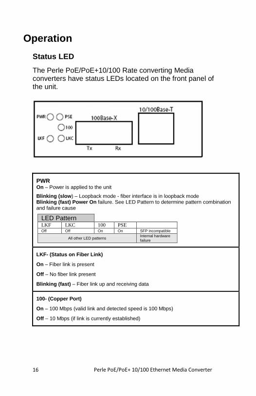
Status LED
The Perle PoE/PoE+10/100 Rate converting Media converters have status LEDs located on the front panel of the unit.
PWR On – Power is applied to the unit
Blinking (slow ) – Loopback mode - fiber interface is in loopback mode Blinking (fast) Power On failure. See LED Pattern to determine pattern combination and failure cause
LED Pattern LKF LKC 100 PSE Off Off On On SFP incompatible
All other LED patterns Internal hardware failure
LKF- (Status on Fiber Link)
On – Fiber link is present
Off – No fiber link present
Blinking (fast) – Fiber link up and receiving data
100- (Copper Port)
On – 100 Mbps (valid link and detected speed is 100 Mbps)
Off – 10 Mbps (if link is currently established)
Perle PoE/PoE+ 10/100 Ethernet Media Converter
17
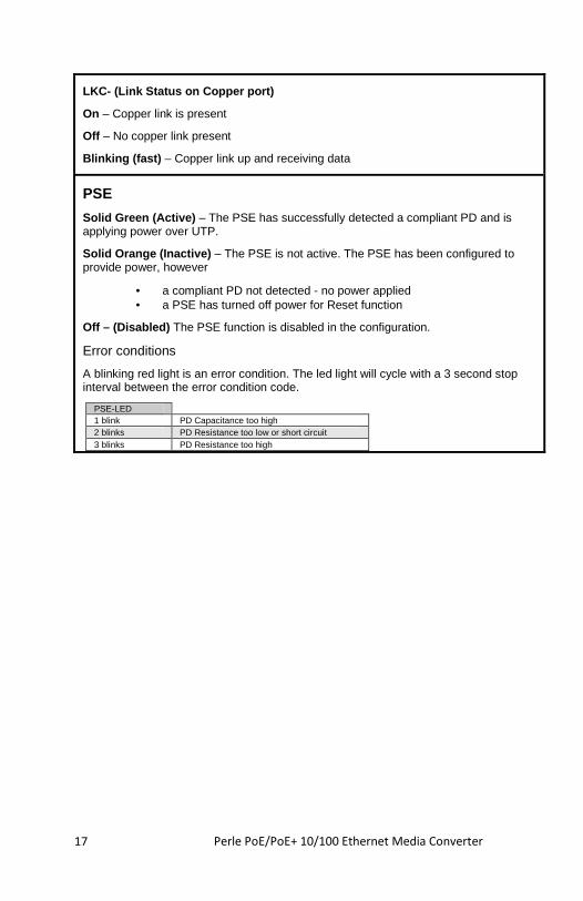
LKC- (Link Status on Copper port)
On – Copper link is present
Off – No copper link present
Blinking (fast) – Copper link up and receiving data
PSE
Solid Green (Active) – The PSE has successfully detected a compliant PD and is applying power over UTP.
Solid Orange (Inactive) – The PSE is not active. The PSE has been configured to provide power, however
• a compliant PD not detected - no power applied • a PSE has turned off power for Reset function
Off – (Disabled) The PSE function is disabled in the configuration.
Error conditions
A blinking red light is an error condition. The led light will cycle with a 3 second stop interval between the error condition code.
PSE-LED 1 blink PD Capacitance too high 2 blinks PD Resistance too low or short circuit 3 blinks PD Resistance too high
Perle PoE/PoE+ 10/100 Ethernet Media Converter
18
Other Features
Auto-MDIX
Auto-MDIX (automatic medium-dependent interface crossover) detects the signalling on the 10/100BASE-T interface to determine the type of cable connected (straight-through or crossover) and automatically configures the connection.
Pause (IEEE 802.3xy)
Integrated Pause signalling is an IEEE feature that temporarily suspends data transmission between two devices in the event that one of the devices becomes overwhelmed with data. The Perle media converter can generate and respond to Pause messages. If Auto negotiation is set to On, the media converter will advertise symmetrical and asymmetrical pause. If Auto negotiation is set to Off, the Pause receive and send will be disabled.
Perle PoE/PoE+ 10/100 Ethernet Media Converter
19
Troubleshooting
General
1. Ensure power is supplied to the media converter. Only the Perle provided power supply may be used.
2. Ensure the remote device’s fiber connection type is compatible with the media converter. If using a simplex fiber connection, ensure that you have both an Upstream (U) and Downstream (D) media converter.
3. Ensure all cabling is of the correct type and is in good working order.
4. For duplex fiber connections, ensure the RX and TX has been reversed between the two media converters.
No connectivity
If unable to get full connectivity with all DIP switches in the UP position, this procedure is recommended for troubleshooting.
Method 1
1. Set the Link Pass-Through mode to Standard on both media converters. Leave all other switches in the Up position.
2. Connect the copper device to the copper port on the media converter. The LKC LED light indicates good copper connection. If the LKC LED is not lit, then check the copper cable and the attached device.
3. Repeat for the far end media converter.
4. Connect the fiber cable to both media converters. The LKF LED indicates good fiber connection. If no LKF LED then check the fiber cabling. Ensure the transmitter and receiver pairs are crossed.
5. Return units to desired configuration.
Perle PoE/PoE+ 10/100 Ethernet Media Converter
20
Method 2:
The fiber connection can also be verified by configuring the remote media converter for loopback mode. The LKF LEDs on both media converters should be lit. Data should pass through the local converter, over the fiber connection to the remote media converter. At the remote media converter, the data will be looped back and passed through the fiber, back to the local converter and passed to the copper link.
No Power to the PD
1. Ensure that the PD is compatible with the S-110P. If the PD is a POE+ device then a POE+ media converter must be used (S-110PP)
2. Ensure that the power supply being used is the one provided with the product
3. If the PD does not support Alternative A (including Legacy PD’s), the Power Option Jumpers must be set accordingly. Also ensure the correct pin out for the device.
4. For proper detection of different classes of devices, the dip switches must be set correctly.
Perle PoE/PoE+ 10/100 Ethernet Media Converter
21
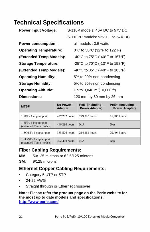
Technical Specifications Power Input Voltage: S-110P models: 46V DC to 57V DC
S-110PP models: 52V DC to 57V DC
Power consumption : all models : 3.5 watts
Operating Temperature: 0°C to 50°C (32°F to 122°F)
(Extended Temp Models): -40°C to 75°C (-40°F to 167°F)
Storage Temperature: -25°C to 70°C (-13°F to 158°F)
(Extended Temp Models): -40°C to 85°C (-40°F to 185°F)
Operating Humidity: 5% to 90% non-condensing
Storage Humidity: 5% to 95% non-condensing
Operating Altitude: Up to 3,048 m (10,000 ft)
Dimensions: 120 mm by 80 mm by 26 mm
MTBF No Power Adapter
PoE (including Power Adapter)
PoE+ (including Power Adapter)
1 SFP / 1 copper port 437,237 hours 229,220 hours 81,386 hours
1 SFP / 1 copper port (extended Temp models)
446,216 hours N/A N/A
1 SC/ST / 1 copper port 385,526 hours 214,161 hours 79,404 hours
1 SC/ST / 1 copper port (extended Temp models)
392,490 hours N/A N/A
Fiber Cabling Requirements: MM: 50/125 microns or 62.5/125 microns
SM: 9/125 microns
Ethernet Copper Cabling Requirements: • Category 5 UTP or STP
• 24-22 AWG
• Straight through or Ethernet crossover
Note: Please refer the product page on the Perle we bsite for the most up to date models and specifications. http://www.perle.com/
Perle PoE/PoE+ 10/100 Ethernet Media Converter
22
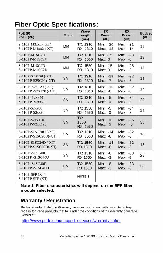
Fiber Optic Specifications: PoE (P) PoE+ (PP) Mode
Wave length (nm)
TX Power (dB)
RX Power (dB)
Budget (dB)
S-110P-M2xx2 (-XT) S-110PP-M2xx2 (-XT) MM TX: 1310
RX: 1310 Min: -20 Max: -12
Min: -31 Max: -14
11
S-110P-M1SC2U S-110PP-M1SC2U MM TX: 1310
RX: 1550 Min: -15 Max: 0
Min: -28 Max: -8 13
S-110P-M1SC2D S-110PP-M1SC2D MM TX: 1550
RX: 1310 Min: -15 Max: 0
Min: -28 Max: -8 13
S-110P-S2SC20 (-XT) S-110PP-S2SC20 (-XT) SM TX: 1310
RX: 1310 Min: -18 Max: -7
Min: -32 Max: -3 14
S-110P -S2ST20 (-XT) S-110PP -S2ST20 (-XT) SM TX: 1310
RX: 1310 Min: -15 Max: -8
Min: -32 Max: -3 17
S-110P -S2xx40 S-110PP -S2xx40 SM TX: 1310
RX :1310 Min: -5 Max: 0
Min: -34 Max: -3
29
S-110P-S2xx80 S-110PP-S2xx80 SM TX: 1550
RX: 1550 Min: -5 Max: 0
Min: -34 Max: -3
29
S-110P-S2xx120 S-110PP-S2xx120 SM
TX: 1550 RX: 1550
Min: 0 Max: 5
Min: -35 Max: -3 35
S-110P-S1SC20U (-XT) S-110PP-S1SC20U(-XT) SM TX: 1310
RX: 1550 Min: -14 Max: -8
Min: -32 Max: -3 18
S-110P-S1SC20D (-XT) S-110PP-S1SC20D(-XT) SM TX: 1550
RX:1310 Min: -14 Max: -8
Min: -32 Max: -3 18
S-110P -S1SC40U S-110PP -S1SC40U SM TX: 1310
RX:1550 Min: -8 Max: -3
Min: -33 Max: -3 25
S-110P -S1SC40D S-110PP -S1SC40D SM TX: 1550
RX:1310 Min: -8 Max: -3
Min: -33 Max: -3 25
S-110P-SFP (XT) S-110PP-SFP (XT) NOTE 1
Note 1: Fiber characteristics will depend on the SF P fiber module selected.
Warranty / Registration Perle’s standard Lifetime Warranty provides customers with return to factory repairs for Perle products that fail under the conditions of the warranty coverage. Details at:
http://www.perle.com/support_services/warranty.shtml
Perle PoE/PoE+ 10/100 Ethernet Media Converter
23
Contacting Technical Support Contact information for the Perle Technical Assistance Center (PTAC) can be found at the link below. A Technical Support Query may be made via this web page. www.perle.com/support_services/support_request.shtml
Compliance Information
FCC This product has been found to comply with the limits for a Class A digital device, pursuant to Part 15 of the FCC rules. These limits are designed to provide reasonable protection against harmful interference when the equipment is operated in a commercial environment. This equipment generates, uses, and can radiate radio frequency energy and, if not installed and used in accordance with the instructions in this Guide, may cause harmful interference to radio communications. Operation of this equipment in a residential area is likely to cause harmful interference, in which case the user will be required to correct the interference at his/her own expense.
EN 55022, Class A WARNING This is a Class A product. In a domestic environment this product may cause radio interference in which case the user may be required to take adequate measures.
EN 55024, Class A
Laser Safety – IEC 60825-1:2007 This product meets Class I Laser safety requirements per IEC-60825-1:2007 standard and complies with FDA/CDRH 21 CFR1040.10 and 21CFR1040.11.
WARNING: Visible and invisible laser radiation may be present when cables are not connected. Do not stare into the beam or view the beam directly with optical instruments. Failure to observe this warning could result in an eye injury or blindness.
WARNING: Use of controls, adjustments or the performance of procedures other than those specified herein may result in hazardous radiation exposure.
Copyright
© 2014 Perle Systems Limited : All rights reserved. No part of this document may be reproduced or used in any form without written permission of Perle Systems Limited