Embed Size (px)
Citation preview
Pertanika J. Sci. & Technol. 25 (S): 123 - 132 (2017)
SCIENCE & TECHNOLOGYJournal homepage: http://www.pertanika.upm.edu.my/
ISSN: 0128-7680 © 2017 Universiti Putra Malaysia Press.
ARTICLE INFO
Article history:Received: 05 January 2017Accepted: 17 January 2017
E-mail addresses: [email protected] (Dee, S.),[email protected] (Singh, B.),[email protected] (Remeli, M. F.),[email protected] (Tan, L.),[email protected] (Oberoi, A.) *Corresponding Author
Concentrated Solar Thermal Thermoelectric Power Generation under Natural and Forced Convection Cooling
Dee, S.1, Singh, B.1*, Remeli, M. F.1, Tan, L.2 and Oberoi, A.3 1Faculty of Mechanical Engineering, Universiti Teknologi MARA (UiTM), 40450 Shah Alam, Malaysia2School of Engineering, RMIT University, Bundoora, Victoria, 3083, Australia3Chitkara University, Chandigarh-Patiala National Highway (NH-64), Patiala, Punjab - 140401, India
ABSTRACT
This paper looks at electrical power generation from solar concentrator using thermoelectric generator. An experiment was conducted on a concentrator thermoelectric generator (CTEG) utilising solar thermal energy. The CTEG used a parabolic dish as concentrator with thermoelectric device installed at the focal point to convert thermal energy to generate electricity. The investigation covered the cooling effect of the cold side of the thermoelectric generator using natural and forced convection cooling for optimum output. Forced convection cooling with a fan provided 69% more power output from the CTEG system as the temperature difference across the TEG was greater than the system cooled by natural convection. The outcome of this project showed maximum power output was obtained for the CTEG system cooled by forced convection cooling.
Keywords: Concentrated solar energy, forced convection, thermoelectric generator, thermal energy
INTRODUCTION
Population growth and technological advancement impose heavy demands for
energy (Fan, Singh, & Akbarzadeh, 2010) namely fossil fuels, such as natural gas, oil and coal (Xie, Dai, Wang, & Sumathy, 2011). However, there is also an environmental cost. Biomass, solar, wind and other renewable energy are able to sustain our demand and overcome environmental problems caused by rapid industrialisation (Zhu, Matsuura, Suzuki, & Tsuchiya, 2014) while fossil fuels are non-renewable energy that takes billions of years to replenish and their depletion rate is faster than their replacement (Eswaramoorthy, Shanmugam, & Veerappan, 2013).
Dee, S., Singh, B., Remeli, M. F., Tan, L. and Oberoi, A.
124 Pertanika J. Sci. & Technol. 25 (S): 123 - 132 (2017)
As the world’s supply of the fossil fuels shrinks, there is a great need for renewable energy, which is clean and affordable, to meet global energy demand (Barlev, Vidu, & Stroeve, 2011). Currently, renewable energy resources have become important due to their demand and capacity to supply sustainable electricity generation system (Khan & Arsalan, 2016). This is coupled with interest in sustainable power production and the need to reduce CO2 emissions (Benoit, Sprea, Gauthier, & Flamant, 2016).
The solar energy is the most reliable and sustainable energy resource for production of electric and thermal energy (Kossyvakis, Vossou, Provatidis, & Hristoforou, 2015). It is considered as the largest and widely distributed renewable energy resource on the planet and can be utilised in many applications either in passive or active solar architecture such as solar water heating, photovoltaic electricity generation and solar thermal generation (Zhang et al., 2013). The solar energy application can be categorised under solar thermal or solar photovoltaic (Ong, 2015). Two technologies can be used to convert solar energy to electricity. The photovoltaic converts sunlight into electricity directly, without resorting to any heat engine, using solar cells. Solar thermal technologies on the other hand convert solar energy into thermal energy, which can be used to run heat engines to produce electricity.
Photovoltaic systems are largely and widely used in domestic applications. The solar thermal system is generally used to generate electricity by utilising heat energy to produce steam to run turbines. This system is very bulky and requires very high maintenance. Alternatively, the solar thermal system can be used for power generation using thermoelectric generator (TEG) to generate electricity. The solar thermal conversion system technology can be implemented using the TEG without the use of the photovoltaic (Trinh, Gonz, Lesage, Wa, & Ha, 2014). The TEG provides an alternative to power generation using concentrated solar energy as compared to steam engines. It is more reliable, robust and acts as a solid-state heat engine for thermal energy to electrical energy conversion. The solar thermal collector can be classified into two categories based on the concentrate ratio: concentrating and non-concentrating (Tian & Zhao, 2013). The concentrator that utilises lens are not able to focus scattered light. The solar concentrating solar thermal thermoelectric consists of thermal collector and a device generator.
The thermoelectric generator (TEG) is based on the concept of Seebeck effect, converting thermal energy to electricity. The thermoelectric device is most commonly used as heat pumps for cooling (Singh et al., 2015). The TEG can also act as a heat engine to produce electricity from heat sources. The TEG is unlike the heat engine which has many parts. It is in the form of solid state, economical, extremely reliable, compact and safe device. The thermo elements in a TEG consist of n-type and p-type semiconductors, and connected electrically in series and thermally in parallel. The output power and the performance of the TEG not only depends on the material properties but also the geometric structure (Singh, Tan, Date, & Akbarzadeh, 2012). With recent developments in the TEG technologies, integration of TEG for power generation promises a sustainable way of generating electricity from solar energy.
MATERIALS AND METHOD
In this work, an experiment was conducted on a concentrator thermoelectric generator (CTEG) using solar thermal energy. The CTEG system consists of parabolic dish collector with an
Concentrated Solar Thermal Thermoelectric Power Generation
125Pertanika J. Sci. & Technol. 25 (S): 123 - 132 (2017)
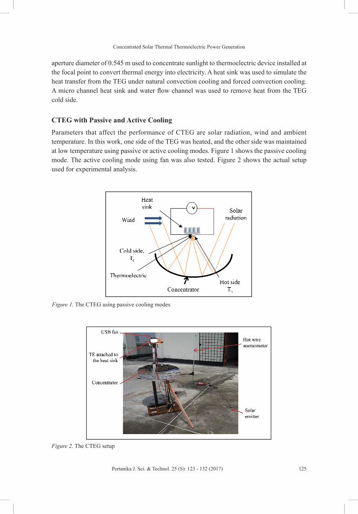
aperture diameter of 0.545 m used to concentrate sunlight to thermoelectric device installed at the focal point to convert thermal energy into electricity. A heat sink was used to simulate the heat transfer from the TEG under natural convection cooling and forced convection cooling. A micro channel heat sink and water flow channel was used to remove heat from the TEG cold side.
CTEG with Passive and Active Cooling
Parameters that affect the performance of CTEG are solar radiation, wind and ambient temperature. In this work, one side of the TEG was heated, and the other side was maintained at low temperature using passive or active cooling modes. Figure 1 shows the passive cooling mode. The active cooling mode using fan was also tested. Figure 2 shows the actual setup used for experimental analysis.
In this work, an experiment was conducted on a concentrator thermoelectric generator (CTEG)
using solar thermal energy. The CTEG system consists of parabolic dish collector with an
aperture diameter of 0.545 m used to concentrate sunlight to thermoelectric device installed at the
focal point to convert thermal energy into electricity. A heat sink was used to simulate the heat
transfer from the TEG under natural convection cooling and forced convection cooling. A micro
channel heat sink and water flow channel was used to remove heat from the TEG cold side.
CTEG with Passive and Active Cooling
Parameters that affect the performance of CTEG are solar radiation, wind and ambient
temperature. In this work, one side of the TEG was heated, and the other side was maintained at
low temperature using passive or active cooling modes. Figure 1 shows the passive cooling mode.
The active cooling mode using fan was also tested. Figure 2 shows the actual setup used for
experimental analysis.
Figure 1. The CTEG using passive cooling modes Figure 1. The CTEG using passive cooling modes
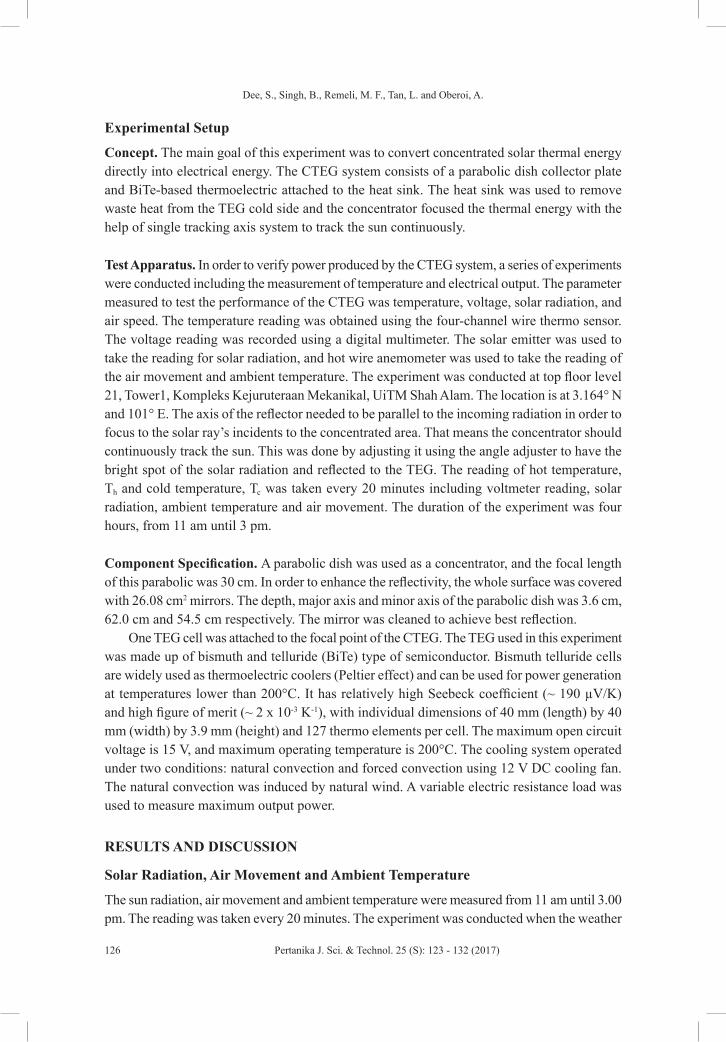
Figure 2. The CTEG setup
Experimental Setup
Concept. The main goal of this experiment was to convert concentrated solar thermal energy
directly into electrical energy. The CTEG system consists of a parabolic dish collector plate and
BiTe-based thermoelectric attached to the heat sink. The heat sink was used to remove waste heat
from the TEG cold side and the concentrator focused the thermal energy with the help of single
tracking axis system to track the sun continuously.
Test Apparatus. In order to verify power produced by the CTEG system, a series of experiments
were conducted including the measurement of temperature and electrical output. The parameter
measured to test the performance of the CTEG was temperature, voltage, solar radiation, and air
speed. The temperature reading was obtained using the four-channel wire thermo sensor. The
voltage reading was recorded using a digital multimeter. The solar emitter was used to take the
reading for solar radiation, and hot wire anemometer was used to take the reading of the air
Figure 2. The CTEG setup
Dee, S., Singh, B., Remeli, M. F., Tan, L. and Oberoi, A.
126 Pertanika J. Sci. & Technol. 25 (S): 123 - 132 (2017)
Experimental Setup
Concept. The main goal of this experiment was to convert concentrated solar thermal energy directly into electrical energy. The CTEG system consists of a parabolic dish collector plate and BiTe-based thermoelectric attached to the heat sink. The heat sink was used to remove waste heat from the TEG cold side and the concentrator focused the thermal energy with the help of single tracking axis system to track the sun continuously.
Test Apparatus. In order to verify power produced by the CTEG system, a series of experiments were conducted including the measurement of temperature and electrical output. The parameter measured to test the performance of the CTEG was temperature, voltage, solar radiation, and air speed. The temperature reading was obtained using the four-channel wire thermo sensor. The voltage reading was recorded using a digital multimeter. The solar emitter was used to take the reading for solar radiation, and hot wire anemometer was used to take the reading of the air movement and ambient temperature. The experiment was conducted at top floor level 21, Tower1, Kompleks Kejuruteraan Mekanikal, UiTM Shah Alam. The location is at 3.164° N and 101° E. The axis of the reflector needed to be parallel to the incoming radiation in order to focus to the solar ray’s incidents to the concentrated area. That means the concentrator should continuously track the sun. This was done by adjusting it using the angle adjuster to have the bright spot of the solar radiation and reflected to the TEG. The reading of hot temperature, Th and cold temperature, Tc was taken every 20 minutes including voltmeter reading, solar radiation, ambient temperature and air movement. The duration of the experiment was four hours, from 11 am until 3 pm.
Component Specification. A parabolic dish was used as a concentrator, and the focal length of this parabolic was 30 cm. In order to enhance the reflectivity, the whole surface was covered with 26.08 cm2 mirrors. The depth, major axis and minor axis of the parabolic dish was 3.6 cm, 62.0 cm and 54.5 cm respectively. The mirror was cleaned to achieve best reflection.
One TEG cell was attached to the focal point of the CTEG. The TEG used in this experiment was made up of bismuth and telluride (BiTe) type of semiconductor. Bismuth telluride cells are widely used as thermoelectric coolers (Peltier effect) and can be used for power generation at temperatures lower than 200°C. It has relatively high Seebeck coefficient (~ 190 µV/K) and high figure of merit (~ 2 x 10⁻³ K-1), with individual dimensions of 40 mm (length) by 40 mm (width) by 3.9 mm (height) and 127 thermo elements per cell. The maximum open circuit voltage is 15 V, and maximum operating temperature is 200°C. The cooling system operated under two conditions: natural convection and forced convection using 12 V DC cooling fan. The natural convection was induced by natural wind. A variable electric resistance load was used to measure maximum output power.
RESULTS AND DISCUSSION
Solar Radiation, Air Movement and Ambient Temperature
The sun radiation, air movement and ambient temperature were measured from 11 am until 3.00 pm. The reading was taken every 20 minutes. The experiment was conducted when the weather
Concentrated Solar Thermal Thermoelectric Power Generation
127Pertanika J. Sci. & Technol. 25 (S): 123 - 132 (2017)
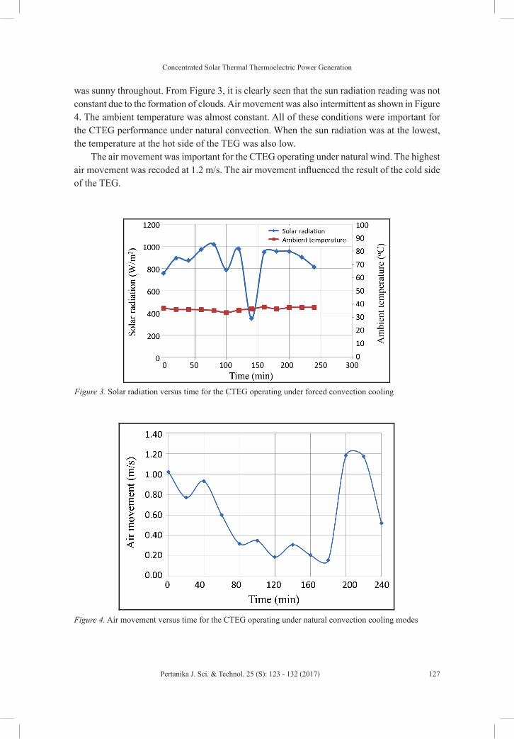
was sunny throughout. From Figure 3, it is clearly seen that the sun radiation reading was not constant due to the formation of clouds. Air movement was also intermittent as shown in Figure 4. The ambient temperature was almost constant. All of these conditions were important for the CTEG performance under natural convection. When the sun radiation was at the lowest, the temperature at the hot side of the TEG was also low.
The air movement was important for the CTEG operating under natural wind. The highest air movement was recoded at 1.2 m/s. The air movement influenced the result of the cold side of the TEG.
RESULTS AND DISCUSSION
Solar Radiation, Air Movement and Ambient Temperature
The sun radiation, air movement and ambient temperature were measured from 11 am until 3.00
pm. The reading was taken every 20 minutes. The experiment was conducted when the weather
was sunny throughout. From Figure 3, it is clearly seen that the sun radiation reading was not
constant due to the formation of clouds. Air movement was also intermittent as shown in Figure
4. The ambient temperature was almost constant. All of these conditions were important for the
CTEG performance under natural convection. When the sun radiation was at the lowest, the
temperature at the hot side of the TEG was also low.
The air movement was important for the CTEG operating under natural wind. The highest air
movement was recoded at 1.2 m/s. The air movement influenced the result of the cold side of the
TEG.
Figure 3. Solar radiation versus time for the CTEG operating under forced convection cooling Figure 3. Solar radiation versus time for the CTEG operating under forced convection cooling
Figure 4. Air movement versus time for the CTEG operating under natural convection cooling modes
Thermoelectric Differential and Electrical Potential
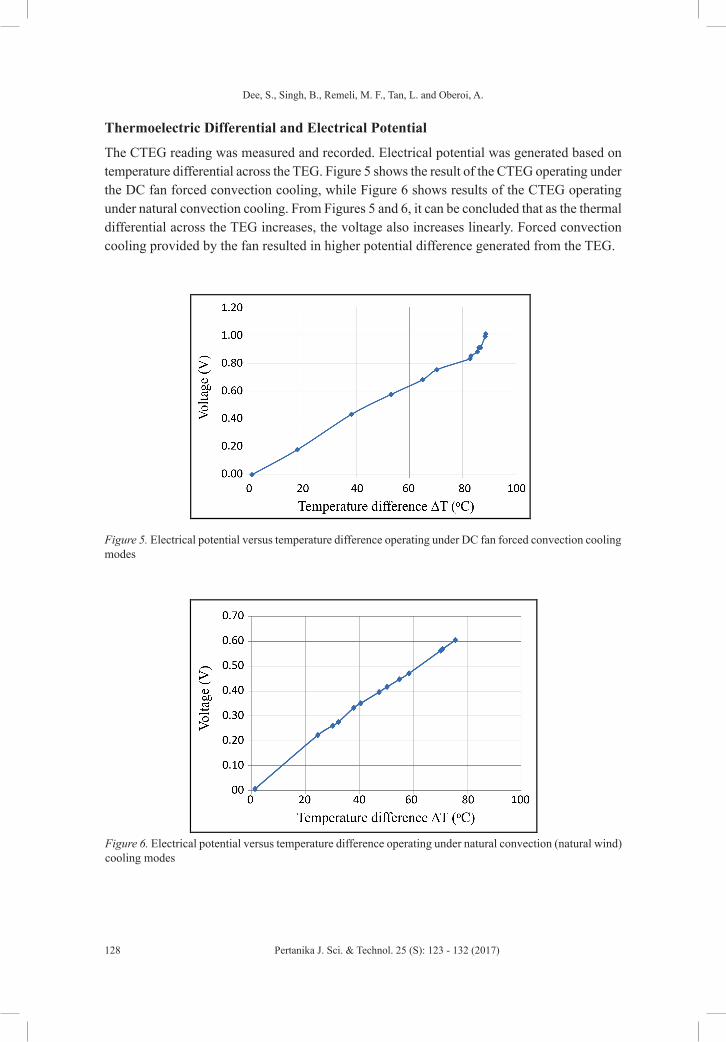
The CTEG reading was measured and recorded. Electrical potential was generated based on
temperature differential across the TEG. Figure 5 shows the result of the CTEG operating under
the DC fan forced convection cooling, while Figure 6 shows results of the CTEG operating under
natural convection cooling. From Figures 5 and 6, it can be concluded that as the thermal
differential across the TEG increases, the voltage also increases linearly. Forced convection
cooling provided by the fan resulted in higher potential difference generated from the TEG.
Figure 4. Air movement versus time for the CTEG operating under natural convection cooling modes
Dee, S., Singh, B., Remeli, M. F., Tan, L. and Oberoi, A.
128 Pertanika J. Sci. & Technol. 25 (S): 123 - 132 (2017)
Thermoelectric Differential and Electrical Potential
The CTEG reading was measured and recorded. Electrical potential was generated based on temperature differential across the TEG. Figure 5 shows the result of the CTEG operating under the DC fan forced convection cooling, while Figure 6 shows results of the CTEG operating under natural convection cooling. From Figures 5 and 6, it can be concluded that as the thermal differential across the TEG increases, the voltage also increases linearly. Forced convection cooling provided by the fan resulted in higher potential difference generated from the TEG.
Figure 4. Air movement versus time for the CTEG operating under natural convection cooling modes
Thermoelectric Differential and Electrical Potential
The CTEG reading was measured and recorded. Electrical potential was generated based on
temperature differential across the TEG. Figure 5 shows the result of the CTEG operating under
the DC fan forced convection cooling, while Figure 6 shows results of the CTEG operating under
natural convection cooling. From Figures 5 and 6, it can be concluded that as the thermal
differential across the TEG increases, the voltage also increases linearly. Forced convection
cooling provided by the fan resulted in higher potential difference generated from the TEG.
Figure 5. Electrical potential versus temperature difference operating under DC fan forced convection cooling modesFigure 5. Electrical potential versus temperature difference operating under DC fan forced convection
cooling modes
Figure 6. Electrical potential versus temperature difference operating under natural convection (natural
wind) cooling modes
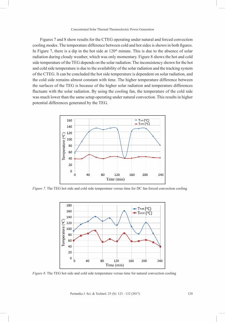
Figures 7 and 8 show results for the CTEG operating under natural and forced convection
cooling modes. The temperature difference between cold and hot sides is shown in both figures.
In Figure 7, there is a dip in the hot side at 120th minute. This is due to the absence of solar
radiation during cloudy weather, which was only momentary. Figure 8 shows the hot and cold
side temperature of the TEG depends on the solar radiation. The inconsistency shown for the hot
and cold side temperature is due to the availability of the solar radiation and the tracking system
of the CTEG. It can be concluded the hot side temperature is dependent on solar radiation, and
the cold side remains almost constant with time. The higher temperature difference between the
surfaces of the TEG is because of the higher solar radiation and temperature differences fluctuate
with the solar radiation. By using the cooling fan, the temperature of the cold side was much
Figure 6. Electrical potential versus temperature difference operating under natural convection (natural wind) cooling modes
Concentrated Solar Thermal Thermoelectric Power Generation
129Pertanika J. Sci. & Technol. 25 (S): 123 - 132 (2017)
Figures 7 and 8 show results for the CTEG operating under natural and forced convection cooling modes. The temperature difference between cold and hot sides is shown in both figures. In Figure 7, there is a dip in the hot side at 120th minute. This is due to the absence of solar radiation during cloudy weather, which was only momentary. Figure 8 shows the hot and cold side temperature of the TEG depends on the solar radiation. The inconsistency shown for the hot and cold side temperature is due to the availability of the solar radiation and the tracking system of the CTEG. It can be concluded the hot side temperature is dependent on solar radiation, and the cold side remains almost constant with time. The higher temperature difference between the surfaces of the TEG is because of the higher solar radiation and temperature differences fluctuate with the solar radiation. By using the cooling fan, the temperature of the cold side was much lower than the same setup operating under natural convection. This results in higher potential differences generated by the TEG.
lower than the same setup operating under natural convection. This results in higher potential
differences generated by the TEG.
Figure 7. The TEG hot side and cold side temperature versus time for DC fan forced convection cooling
Figure 8. The TEG hot side and cold side temperature versus time for natural convection cooling
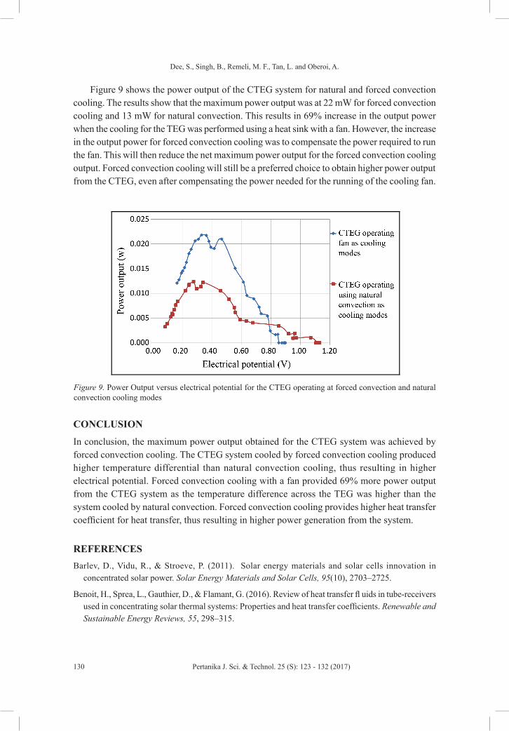
Figure 9 shows the power output of the CTEG system for natural and forced convection
cooling. The results show that the maximum power output was at 22 mW for forced convection
cooling and 13 mW for natural convection. This results in 69% increase in the output power when
the cooling for the TEG was performed using a heat sink with a fan. However, the increase in the
output power for forced convection cooling was to compensate the power required to run the fan.
Figure 7. The TEG hot side and cold side temperature versus time for DC fan forced convection cooling
lower than the same setup operating under natural convection. This results in higher potential
differences generated by the TEG.
Figure 7. The TEG hot side and cold side temperature versus time for DC fan forced convection cooling
Figure 8. The TEG hot side and cold side temperature versus time for natural convection cooling
Figure 9 shows the power output of the CTEG system for natural and forced convection
cooling. The results show that the maximum power output was at 22 mW for forced convection
cooling and 13 mW for natural convection. This results in 69% increase in the output power when
the cooling for the TEG was performed using a heat sink with a fan. However, the increase in the
output power for forced convection cooling was to compensate the power required to run the fan.
Figure 8. The TEG hot side and cold side temperature versus time for natural convection cooling
Dee, S., Singh, B., Remeli, M. F., Tan, L. and Oberoi, A.
130 Pertanika J. Sci. & Technol. 25 (S): 123 - 132 (2017)
Figure 9 shows the power output of the CTEG system for natural and forced convection cooling. The results show that the maximum power output was at 22 mW for forced convection cooling and 13 mW for natural convection. This results in 69% increase in the output power when the cooling for the TEG was performed using a heat sink with a fan. However, the increase in the output power for forced convection cooling was to compensate the power required to run the fan. This will then reduce the net maximum power output for the forced convection cooling output. Forced convection cooling will still be a preferred choice to obtain higher power output from the CTEG, even after compensating the power needed for the running of the cooling fan.
This will then reduce the net maximum power output for the forced convection cooling output.
Forced convection cooling will still be a preferred choice to obtain higher power output from the
CTEG, even after compensating the power needed for the running of the cooling fan.
Figure 9. Power Output versus electrical potential for the CTEG operating at forced convection and
natural convection cooling modes
CONCLUSION
In conclusion, the maximum power output obtained for the CTEG system was achieved by forced
convection cooling. The CTEG system cooled by forced convection cooling produced higher
temperature differential than natural convection cooling, thus resulting in higher electrical
potential. Forced convection cooling with a fan provided 69% more power output from the CTEG
system as the temperature difference across the TEG was higher than the system cooled by
natural convection. Forced convection cooling provides higher heat transfer coefficient for heat
transfer, thus resulting in higher power generation from the system.
Figure 9. Power Output versus electrical potential for the CTEG operating at forced convection and natural convection cooling modes
CONCLUSION
In conclusion, the maximum power output obtained for the CTEG system was achieved by forced convection cooling. The CTEG system cooled by forced convection cooling produced higher temperature differential than natural convection cooling, thus resulting in higher electrical potential. Forced convection cooling with a fan provided 69% more power output from the CTEG system as the temperature difference across the TEG was higher than the system cooled by natural convection. Forced convection cooling provides higher heat transfer coefficient for heat transfer, thus resulting in higher power generation from the system.
REFERENCESBarlev, D., Vidu, R., & Stroeve, P. (2011). Solar energy materials and solar cells innovation in
concentrated solar power. Solar Energy Materials and Solar Cells, 95(10), 2703–2725.
Benoit, H., Sprea, L., Gauthier, D., & Flamant, G. (2016). Review of heat transfer fl uids in tube-receivers used in concentrating solar thermal systems: Properties and heat transfer coefficients. Renewable and Sustainable Energy Reviews, 55, 298–315.
Concentrated Solar Thermal Thermoelectric Power Generation
131Pertanika J. Sci. & Technol. 25 (S): 123 - 132 (2017)
Eswaramoorthy, M., Shanmugam, S., & Veerappan, A. R. (2013). Experimental study on solar parabolic dish thermoelectric generator. International Journal of Energy Engineering (IJEE) Jun. 2013, 3(3), 62-66.
Fan, H., Singh, R., & Akbarzadeh, A. (2010). Power generation from thermoelectric cells by using high concentrated solar dish. Proceedings of the Solar10, the 48th ANZSES Annual Conference.
Khan, J., & Arsalan, M. H. (2016). Solar power technologies for sustainable electricity generation – A review. Renewable and Sustainable Energy Reviews, 55, 414–425.
Kossyvakis, D. N., Vossou, C. G., Provatidis, C. G., & Hristoforou, E. V. (2015). Computational analysis and performance optimization of a solar thermoelectric generator. Renewable Energy, 81, 150–161.
Ong, K. S. (2015). Review of solar, heat pipe and thermoelectric hybrid systems for power generation and heating. International Journal of Low-Carbon Technologies, 1–6.
Singh, B., Saoud, A., Remeli, M. F., Ding, L. C., Date, A., & Akbarzadeh, A. (2015). Design and construction of a simple thermoelectric generator heat exchanger for power generation from salinity gradient solar pond. Jurnal Teknologi, 76(5), 21-24.
Singh, B., Tan, L. P., Date, A., & Akbarzadeh, A. (2012).Power generation from salinity gradient solar pond using thermoelectric generators for renewable energy application. 2012 IEEE International Conference on Power and Energy (PECon), 89-92.
Tian Y., & Zhao, C. Y. (2013). A review of solar collectors and thermal energy storage in solar thermal application. Applied Energy, 104, 538–553.
Trinh, J. C. S. V. A., Gonz, I., Lesage, J., Wa, S. S., & Ha, M. (2014). Solar thermal energy conversion to electrical power. Applied Thermal Engineering, 70, 675–686.
Xie, W. T., Dai, Y. J., Wang, R. Z., & Sumathy, K. (2011). Concentrated solar energy applications using Fresnel lenses: A review. Renewable and Sustainable Energy Reviews, 15(6), 2588–2606.
Zhang, M., Miao, L., Pu, Y., Tanemura, S., Fisher, C. A. J., Xu, G., Xin, C., & Zhu, G. (2013). Efficient , low-cost solar thermoelectric cogenerators comprising evacuated tubular solar collectors and thermoelectric modules. Applied Energy, 109, 51–59.
Zhu, N., Matsuura, T., Suzuki, R., & Tsuchiya, T. (2014). Development of a small solar power generation system based on TEG. Energy Procedia, 52, 651–658.