Embed Size (px)
Citation preview
Proceedings of the Workshop
Pervasive Mobile Interaction Devices
(PERMID 2005)
- Mobile Devices as Pervasive User Interfaces and Interaction Devices -
http://www.medien.ifi.lmu.de/permid2005/
in Conjunction with the
3rd International Conference on Pervasive Computing (Pervasive 2005)
Enrico Rukzio, Jonna Hakkila, Mirjana Spasojevic, Jani Mäntyjärvi, Nishkam Ravi (Eds.)
May 2005
Preface
Welcome to the Pervasive 2005 workshop Pervasive Mobile Interaction Devices (PERMID 2005) - Mobile Devices as Pervasive User Interfaces and Interaction Devices -. The workshop consists of 13 interesting papers which were reviewed by at least 2 PC members to help the authors to improve their papers for the camera ready version. We would like to thank the authors for their contributions and the organizers of PERVASIVE 2005 for hosting PERMID 2005. Furthermore we would like to thank the Media Informatics Group at the University of Munich and the IST Project Simplicity funded by the EU for their support to publish this workshop record in a printed form. We look forward to the workshop providing a rich environment for academia and industry to foster active collaboration in the development of pervasive mobile interaction devices. Munich, May 11th 2005
Enrico Rukzio, Jonna Hakkila, Mirjana Spasojevic, Jani Mäntyjärvi, Nishkam Ravi
Theme of the Workshop
Mobile devices have become a pervasive part of our everyday live. People have mobile phones, smartphones and PDAs with them nearly always and everywhere. So far these mobile devices have been mostly used for phone calls, writing short messages and organizer functionalities. Currently we see that the development of context-aware services for mobile phones takes particularly the user, his situation, and the location into account. But why not use these devices for interactions with the real world, as a mediator between the virtual and the user’s world? While certain research domains within the fields of mobile applications and services advance at an amazing speed (e.g. context-aware services on mobile devices, using the sensors of mobile phones), the areas of pervasive mobile user interfaces, mobile devices as interaction devices, mobile devices for interactions with the physical world and user experiences in this field are still rather limited.
Goals
The main goal of the workshop is to develop an understanding of how mobile devices (particularly mobile phones, smartphones and PDAs) can be used as interaction devices. We will provide a forum to share information, results, and ideas on current research in this area. Furthermore we aim to develop new ideas on how mobile phones can be exploited for new forms of interaction with the environment. We will bring together researchers and practitioners who are concerned with design, development, and implementation of new applications and services using personal mobile devices as user interfaces.
Topics
Possible topics for the workshop include (but are not limited to): • Interactions between mobile devices and the real world • Augmented, virtual and mixed reality on mobile phones and PDAs • Using mobile devices as user interfaces for terminals and vending machines • Portable music players and personal servers as mobile interaction devices • Multimodal interaction taking mobile devices into account • Usage of sensors of mobile devices for pervasive applications • Interaction metaphors for pervasive applications and services • Gathering, management and usage of context information • Interactive context-aware services on mobile devices • User experience, user studies • Applications and scenarios
Webpage
All information about the workshop, the papers and the proceedings are available at the website of the workshop http://www.medien.ifi.lmu.de/permid2005/.
Organizers
Enrico Rukzio Enrico.Rukzio (at) ifi.lmu.de Media Informatics Group, University of Munich Jonna Hakkila Jonna.Hakkila (at) nokia.com Nokia Corporation Mirjana Spasojevic Mirjana.Spasojevic (at) hp.com Hewlett Packard Labs Jani Mäntyjärvi Jani.Mantyjarvi (at) vtt.fi VTT Technical Research Centre of Finland Nishkam Ravi nravi (at) paul.rutgers.edu Rutgers University
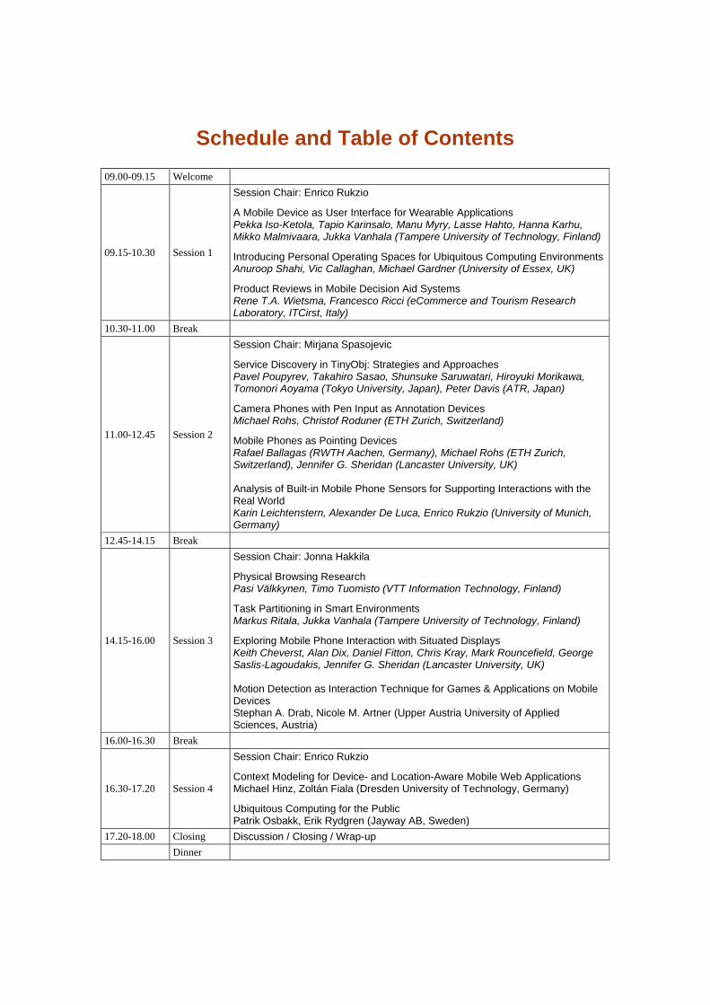
Schedule and Table of Contents
09.00-09.15 Welcome
09.15-10.30 Session 1
Session Chair: Enrico Rukzio A Mobile Device as User Interface for Wearable Applications Pekka Iso-Ketola, Tapio Karinsalo, Manu Myry, Lasse Hahto, Hanna Karhu, Mikko Malmivaara, Jukka Vanhala (Tampere University of Technology, Finland) Introducing Personal Operating Spaces for Ubiquitous Computing EnvironmentsAnuroop Shahi, Vic Callaghan, Michael Gardner (University of Essex, UK) Product Reviews in Mobile Decision Aid Systems Rene T.A. Wietsma, Francesco Ricci (eCommerce and Tourism Research Laboratory, ITCirst, Italy)
10.30-11.00 Break
11.00-12.45 Session 2
Session Chair: Mirjana Spasojevic Service Discovery in TinyObj: Strategies and Approaches Pavel Poupyrev, Takahiro Sasao, Shunsuke Saruwatari, Hiroyuki Morikawa, Tomonori Aoyama (Tokyo University, Japan), Peter Davis (ATR, Japan) Camera Phones with Pen Input as Annotation Devices Michael Rohs, Christof Roduner (ETH Zurich, Switzerland) Mobile Phones as Pointing Devices Rafael Ballagas (RWTH Aachen, Germany), Michael Rohs (ETH Zurich, Switzerland), Jennifer G. Sheridan (Lancaster University, UK) Analysis of Built-in Mobile Phone Sensors for Supporting Interactions with the Real World Karin Leichtenstern, Alexander De Luca, Enrico Rukzio (University of Munich, Germany)
12.45-14.15 Break
14.15-16.00 Session 3
Session Chair: Jonna Hakkila Physical Browsing Research Pasi Välkkynen, Timo Tuomisto (VTT Information Technology, Finland) Task Partitioning in Smart Environments Markus Ritala, Jukka Vanhala (Tampere University of Technology, Finland) Exploring Mobile Phone Interaction with Situated Displays Keith Cheverst, Alan Dix, Daniel Fitton, Chris Kray, Mark Rouncefield, George Saslis-Lagoudakis, Jennifer G. Sheridan (Lancaster University, UK) Motion Detection as Interaction Technique for Games & Applications on Mobile Devices Stephan A. Drab, Nicole M. Artner (Upper Austria University of Applied Sciences, Austria)
16.00-16.30 Break
16.30-17.20 Session 4
Session Chair: Enrico Rukzio Context Modeling for Device- and Location-Aware Mobile Web Applications Michael Hinz, Zoltán Fiala (Dresden University of Technology, Germany) Ubiquitous Computing for the Public Patrik Osbakk, Erik Rydgren (Jayway AB, Sweden)
17.20-18.00 Closing Discussion / Closing / Wrap-up Dinner
A Mobile Device as User Interface for Wearable
Applications
Pekka Iso-Ketola, Tapio Karinsalo, Manu Myry, Lasse Hahto, Hanna Karhu, Mikko Malmivaara and Jukka Vanhala
Tampere University of Technology - Kankaanpää Unit
Jämintie 14, FI-38700, Kankaanpää, Finland
Tel. +3582 5782 7142, fax +3582 5782 7141 (first name.last name)@tut.fi
ABSTRACT In this paper, we describe the Tampere University of Technology’s involvement in the research of machine washable and wirelessly rechargeable wearable technology and using mobile devices as input and output interface and as means of data transfer and processing for wearable applications.
Keywords Wearable technology, smart clothing, wireless wearable system, machine washable electronics
1. INTRODUCTION In the late 1990’s many leading figures of wearable technology predicted that very soon wearables would overthrow the mobile handset and electronics would move in even closer to the user’s body. The prediction is yet to come true and when the high-tech boom slowed down most became more cautious with their estimates. Wearable electronics haven’t still made mass market, but teaming up with mobile devices could eventually solve some of the key problems in wearable applications. The Tampere University of Technology (TUT) has conducted research in wearable technology since 1997 [1]. The TUT Kankaanpää Unit (KP1) was established in 2003 and its research concentrates on wearable technology and garment integrated electronics.
2. THE CHALLENGE Current wearable applications still have several problems to be worked out before mass market. Many of them are related to the maintenance of the device, e.g. machine washing, recharging of batteries and customer service. Bringing a function close to the body can often be of more service than merely delivering hands free operating, but interfacing the wearable devices can be complicated. If the wearable device requires both input and output
and needs to be operated on-the-go, an integrated wearable user interface may cause more problems than it solves. First of all the usability may suffer if for example text input, or any multi-key input must be used; constructing a soft washable keypad is possible [2] but efficient typing may be difficult for lack of suitable rigid surfaces on the body against which to press the keys. If the keypad itself is made rigid the textile garment may no longer carry the added bulk, not to mention the obtrusive appearance. Secondly, for the same reasons high resolution display output is not yet an option as the flexible displays still really aren’t flexible and tough enough to withstand regular garment wear [3]. Woven optical fiber displays [4] are softer in feel and lighter, but so far don’t offer needed resolution or brightness. Thirdly, hard objects larger than a button or a zipper in soft textile are likely to damage the fabric in machine wash. Constructing them waterproof and rigid enough to be able to take a washing cycle is expensive and time-consuming. Finding a perfect location for the display and a keypad is hard from a usability and ergonomic point of view [5]. A shirt with a display can’t show output if the user is wearing a jacket over the shirt. Even further, displays as well as most other output devices consume much energy in relation to sensor electronics and combined with wireless data transfer the overall energy consumption may require larger batteries that add weight and bulk. A good alternative to integrated user interfaces in wearable technology would be to use a wirelessly connected mobile tool, preferably one with good input/output capability, one that is widely available and customizable for different target groups and tasks and one that nearly everyone is already familiar using and carrying along with them. Why make another wireless handset when most people already carry one wherever they go? By making the mobile phone a part of the system the toughest problems of added manufacturing (and purchasing) costs and the maintenance of the garment-integrated electronics could be solved.
http://www.medien.ifi.lmu.de/permid2005/ PERMID 2005
5
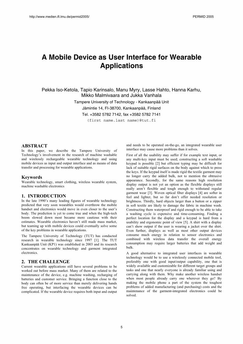
3. THE SOLUTION Figure 1. illustrates a wearable system linked with external devices with a mobile phone as the user interface and communication hub between the personal space and the environment. Many of today’s mobile handsets have inbuilt Bluetooth (BT) or even Wireless Local Area Network (WLAN), and support General Packet Radio System (GPRS) and can run third party applications. A garment with BT fits nicely into the wireless loop and can be accessed through a custom application fitted in a menu structure, which offers the actual service. BT may not be an optimal solution for implementing a Body Area Network (BAN), but, along with IrDa, currently the only standard system widely used in mobile phones. On the other hand BT is a more suitable protocol for a Personal Area Network (PAN), which requires a higher bandwidth.
Figure 1. A mobile phone as the user interface and communications hub for wearable electronics.
3.1 Body Area Network There are several options for creating a Body Area Network. They can be divided into three categories based on the data transferring method. The first category is the most obvious and old-school, where the data between for example the CPU and the sensors is carried by wiring placed inside the garment. The wiring can be done by commercially available plastic-encased conductive textile yarns. The benefit of this method is that the wiring can include power supply for the sensors. A downside is the added sewing work when assembling the wiring to the garment; also the placement of the wiring needs to be done carefully to avoid dragging and restricting movement. A more sophisticated version of this is to include the conductive traces in the textile in the knitting phase, but for now this is a much too costly method. The traces could also be printed in the textile, but it too can be costly with the print having to withstand stretching, abrasion, moisture and sweat.
The second category builds on using the body’s skin surface for sending signals. This requires a direct skin contact so it is most practical in garments that touch the skin surface. In this alternative all pieces of electronics need to have their own power supply. The third category is wireless data transfer. Its benefits include less need for adapting the garment to the added technology and possibility to use short-range data transfer with moderate power consumption. Bluetooth is a good media for data loads around 1 Mbps, but a sensor-BAN however only moves a few bytes of data at a time and most of the BT channel capacity would be left unused. BT also consumes unnecessarily much power for a BAN. A better option for wireless data transfer in a BAN would be Zigbee [6], which has a capacity of up to 250 Kbps. Other alternatives include Wireless USB (WUSB) or Bluetooth v.2.
3.2 Personal Area Network The BAN concept includes all parts of the wearable system located in the garment (e.g. sensor electronics) but to further include user’s additional mobile devices and applications (e.g. mobile phone, camera, eWallet) we need to expand the concept of communication space from BAN to PAN which includes everything in the user’s close proximity (Personal Space in fig. 1.). The mobile phone serves a role as the mediating user interface between the BAN and PAN for reading the output from the garment sensors and acting as the input device for configuring the wearable device’s settings. The mobile phone can be used to process the garment data; alternatively the phone can send the data further to an external service for processing over either a BT or GPRS or WLAN. Equally, an external device can monitor the environment where the user is located (Smart Environment in fig. 1.) and send input to the wearable system.
4. THE RESEARCH The TUT Kankaanpää Unit is strongly focused on the wearables-infrastructure and has experience in manufacturing machine washable electronics by casting flexible circuit boards (FCB) in soft polymer. Several rounds of casting experiments have been made with help from the polyurethane specialists at Pucast Oy of Vammala, Finland and the results have been very promising; the cast electronics have proven to be unobtrusive and non-restricting.
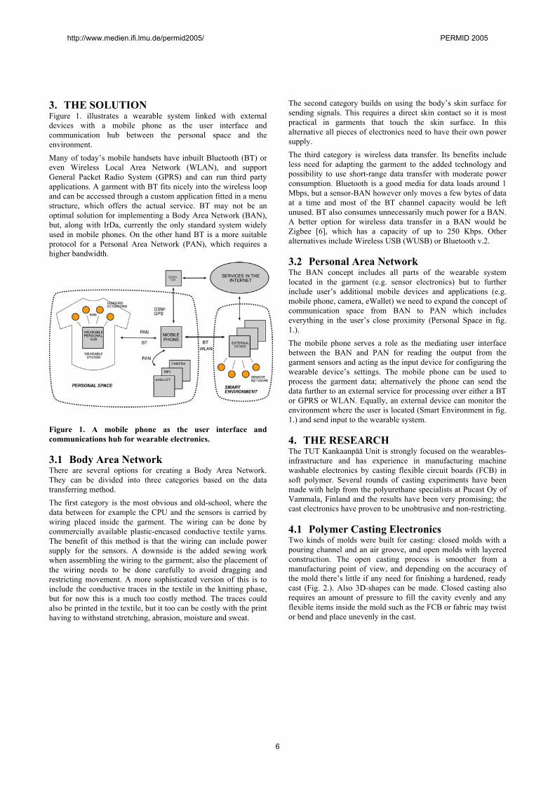
4.1 Polymer Casting Electronics Two kinds of molds were built for casting: closed molds with a pouring channel and an air groove, and open molds with layered construction. The open casting process is smoother from a manufacturing point of view, and depending on the accuracy of the mold there’s little if any need for finishing a hardened, ready cast (Fig. 2.). Also 3D-shapes can be made. Closed casting also requires an amount of pressure to fill the cavity evenly and any flexible items inside the mold such as the FCB or fabric may twist or bend and place unevenly in the cast.
http://www.medien.ifi.lmu.de/permid2005/ PERMID 2005
6
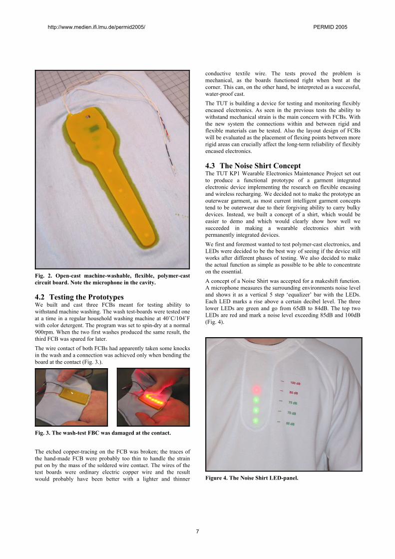
Fig. 2. Open-cast machine-washable, flexible, polymer-cast circuit board. Note the microphone in the cavity.
4.2 Testing the Prototypes We built and cast three FCBs meant for testing ability to withstand machine washing. The wash test-boards were tested one at a time in a regular household washing machine at 40˚C/104˚F with color detergent. The program was set to spin-dry at a normal 900rpm. When the two first washes produced the same result, the third FCB was spared for later. The wire contact of both FCBs had apparently taken some knocks in the wash and a connection was achieved only when bending the board at the contact (Fig. 3.).
Fig. 3. The wash-test FBC was damaged at the contact. The etched copper-tracing on the FCB was broken; the traces of the hand-made FCB were probably too thin to handle the strain put on by the mass of the soldered wire contact. The wires of the test boards were ordinary electric copper wire and the result would probably have been better with a lighter and thinner
conductive textile wire. The tests proved the problem is mechanical, as the boards functioned right when bent at the corner. This can, on the other hand, be interpreted as a successful, water-proof cast. The TUT is building a device for testing and monitoring flexibly encased electronics. As seen in the previous tests the ability to withstand mechanical strain is the main concern with FCBs. With the new system the connections within and between rigid and flexible materials can be tested. Also the layout design of FCBs will be evaluated as the placement of flexing points between more rigid areas can crucially affect the long-term reliability of flexibly encased electronics.
4.3 The Noise Shirt Concept The TUT KP1 Wearable Electronics Maintenance Project set out to produce a functional prototype of a garment integrated electronic device implementing the research on flexible encasing and wireless recharging. We decided not to make the prototype an outerwear garment, as most current intelligent garment concepts tend to be outerwear due to their forgiving ability to carry bulky devices. Instead, we built a concept of a shirt, which would be easier to demo and which would clearly show how well we succeeded in making a wearable electronics shirt with permanently integrated devices. We first and foremost wanted to test polymer-cast electronics, and LEDs were decided to be the best way of seeing if the device still works after different phases of testing. We also decided to make the actual function as simple as possible to be able to concentrate on the essential. A concept of a Noise Shirt was accepted for a makeshift function. A microphone measures the surrounding environments noise level and shows it as a vertical 5 step ‘equalizer’ bar with the LEDs. Each LED marks a rise above a certain decibel level. The three lower LEDs are green and go from 65dB to 84dB. The top two LEDs are red and mark a noise level exceeding 85dB and 100dB (Fig. 4).
Figure 4. The Noise Shirt LED-panel.
http://www.medien.ifi.lmu.de/permid2005/ PERMID 2005
7
Continuous exposure exceeding 85dB is the limit set by the EU authorities for recommended use of hearing protection. The device has a small battery with a wireless recharging induction loop in the neck tab. The garment is functional whenever charged and won’t require any user input.
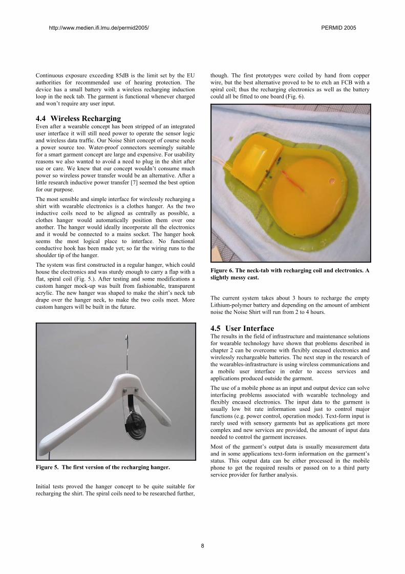
4.4 Wireless Recharging Even after a wearable concept has been stripped of an integrated user interface it will still need power to operate the sensor logic and wireless data traffic. Our Noise Shirt concept of course needs a power source too. Water-proof connectors seemingly suitable for a smart garment concept are large and expensive. For usability reasons we also wanted to avoid a need to plug in the shirt after use or care. We knew that our concept wouldn’t consume much power so wireless power transfer would be an alternative. After a little research inductive power transfer [7] seemed the best option for our purpose. The most sensible and simple interface for wirelessly recharging a shirt with wearable electronics is a clothes hanger. As the two inductive coils need to be aligned as centrally as possible, a clothes hanger would automatically position them over one another. The hanger would ideally incorporate all the electronics and it would be connected to a mains socket. The hanger hook seems the most logical place to interface. No functional conductive hook has been made yet; so far the wiring runs to the shoulder tip of the hanger. The system was first constructed in a regular hanger, which could house the electronics and was sturdy enough to carry a flap with a flat, spiral coil (Fig. 5.). After testing and some modifications a custom hanger mock-up was built from fashionable, transparent acrylic. The new hanger was shaped to make the shirt’s neck tab drape over the hanger neck, to make the two coils meet. More custom hangers will be built in the future.
Figure 5. The first version of the recharging hanger. Initial tests proved the hanger concept to be quite suitable for recharging the shirt. The spiral coils need to be researched further,
though. The first prototypes were coiled by hand from copper wire, but the best alternative proved to be to etch an FCB with a spiral coil; thus the recharging electronics as well as the battery could all be fitted to one board (Fig. 6).
Figure 6. The neck-tab with recharging coil and electronics. A slightly messy cast.
The current system takes about 3 hours to recharge the empty Lithium-polymer battery and depending on the amount of ambient noise the Noise Shirt will run from 2 to 4 hours.
4.5 User Interface The results in the field of infrastructure and maintenance solutions for wearable technology have shown that problems described in chapter 2 can be overcome with flexibly encased electronics and wirelessly rechargeable batteries. The next step in the research of the wearables-infrastructure is using wireless communications and a mobile user interface in order to access services and applications produced outside the garment. The use of a mobile phone as an input and output device can solve interfacing problems associated with wearable technology and flexibly encased electronics. The input data to the garment is usually low bit rate information used just to control major functions (e.g. power control, operation mode). Text-form input is rarely used with sensory garments but as applications get more complex and new services are provided, the amount of input data needed to control the garment increases. Most of the garment’s output data is usually measurement data and in some applications text-form information on the garment’s status. This output data can be either processed in the mobile phone to get the required results or passed on to a third party service provider for further analysis.
http://www.medien.ifi.lmu.de/permid2005/ PERMID 2005
8
5. CONTINUING RESEARCH The polymer-casting research goes on with the TUT Smart Polymer Project, and in the near future we’ll get to cast in rubbers and different plastics. Another promising outlook is to get rid of the circuit board and print the traces on a fabric with conductive ink before casting. This would also require researching textiles as component base. The project could also venture into finding more ways of using cast polymers in wearable electronics, such as interference shielding or conductive polymer sensor patches for body monitoring. The recharging research goes on with customizing the spiral coils for each concept to make them as small as possible and building better custom hangers. Downsizing the recharging electronics continues alongside. The TUT is also starting a new project on implementing wearable elements for well-being and fitness. For this project the use of a mobile phone as user interface is an important feature.
6. THE CONCLUSION Everybody’s still waiting for a wearables market to form and the killer-application to hit the shops, but with more effort and attention paid to the infrastructure around wearable applications both the consumers’ and the manufacturers’ confusion could be eased. So far the few commercial wearable products have been little more than marketing efforts, but when reliable and cost-efficient production technologies are developed, a commercial mass-producible application of wearable technology suddenly does not seem so far away. At least the problems in interfacing and maintenance may soon be solved, quite possibly by means of a mobile device interface and machine washable, fully garment-integrated electronics.
7. REFERENCES [1] Rantanen, J., Impiö, J., Karinsalo, T., Malmivaara, M.,
Reho, A., Tasanen, M. & Vanhala, J., Smart Clothing Prototype for the Arctic Environment, Personal and Ubiquitous Computing, Volume 6, 1, p. 3-16, 2002.
[2] Post, E.R., Orth, M. Smart Fabric or Wearable Clothing, International Symposium on Wearable Computing, Proceedings, p. 167, 1997.
[3] Moore, S.K., Just One Word –Plastics, Organic Semiconductors Could Put Cheap Circuits Everywhere and Make Flexible Displays a Reality, IEEE Spectrum, September 2002, pp. 55-59.
[4] Gould, P. Textiles Gain Intelligence, Materials Today, October 2003, p. 38.
[5] Thomas, B., Grimmer, K., Zucco, J., Milanese, S, Where Does the Mouse Go? An Investigation into the Placement of a Body-Attached TouchPad Mouse for Wearable Computers, Personal and Ubiquitous Computing, Volume 6, 2, pp. 97-112, 2002.
[6] Evans-Pughe, C., Bzzzz zzz [ZigBee wireless standard], IEE Review, March 2003, Volume 49, Issue 3, pp. 28- 31.
[7] Chan-Gyun, K., Dong-Hyun, S., Jong-Hu,P., Cho, B. H. Design of a Contactless Battery Charger for Cellular Phone, IEEE Transactions On Industrial Electronics, pp. 1238-1247, Volume 48, no. 6., December 2001.
http://www.medien.ifi.lmu.de/permid2005/ PERMID 2005
9
Introducing Personal Operating Spaces for UbiquitousComputing Environments
Anuroop ShahiIntelligent Inhabited
Environments Group &Chimera
University of EssexWivenhoe ParkColchester, UK
Vic CallaghanIntelligent InhabitedEnvironments GroupUniversity of Essex
Wivenhoe ParkColchester, UK
Michael GardnerChimera
University of EssexWivenhoe ParkColchester, UK
ABSTRACTPervasive computing environments will combine everydayphysical spaces with network aware devices and services;hence providing computing behaviour that is much moreentwined with the environments we inhabit. Within suchenvironments, a nomadic user will own and make use ofmany services attached to, and organised around, physicalspace. This study introduces the concept of a personal op-erating space: an entity formed for personalisation of spacespecific services, by treating a user’s personal mobile deviceas an identity for personalisation.
1. INTRODUCTIONPervasive computing causes us to examine ways in whichexisting computing infrastructures combine with everydayphysical and environmental spaces; by understanding thedynamics of device rich environments; how devices are net-worked to correspond to the boundaries of physical space;and how users generally interact within and across thesespaces: commonly referred to as ’smart space environments’.To coincide with the vision of pervasive computing, smartspaces will need to become part of the users background en-vironment, and gradually become more ubiquitous in nature.These spaces will allow users to seamlessly access and useservices across the myriad of devices provided by each space.Achieving this level of seamlessness requires true interoper-ability across heterogeneous devices, networks and applica-tions. Much of this work is being lead by standards bodiessuch as the IEEE, OMG, W3C and the UPnP foundation,which all recommend their own standards for addressinginteroperable components needed in smart space environ-ments. Examples include bluetooth for personal area radiocommunication; TCP/IP for network communication; ob-ject and service orientated middle-ware technologies, such
as CORBA and Web Services; and UPnP for communica-tion between everyday devices in buildings. Additionally,methods for semantic interoperability are being realised bythe introduction of semantic web technologies for termino-logy definition and mapping. Services can then use a sharedontology to develop methods for interoperation during spon-taneous interactions (OWL-S). All these technology are wellknown for forming an integral part of any ubiquitous com-puting environment, with the challenge being to combinethese to offer new types of behavior; characterized by be-ing considerably more powerful and seamless than servicestoday.
At the University of Essex, we are examining ways in whichpeople interact with everyday spaces such as intelligent build-ings. People tend to make use of different spaces over time,with each space differing depending on person, group or con-text (such as rooms in a building). People are also visitingforeign environments, such as buildings that offer a rangeof services from application based services, such as mediaapplications, through to heating and light control. Further-more, these nomads are increasingly carrying mobile devices,the most common being smart phones, which are essentiallybeing treated as personal devices. The aim of this work is totreat these ubiquitous personal devices as a mechanism forinteracting with and configuring, in a personalised manner,pervasive computing spaces; therefore creating a personaloperating space between a user’s personal devices and anyservices within the local space. A personal operating spacewill allow a user to both import a personal environment intothe current space, along with personalising any services anddevices provided by the space. This study seeks to buildon theory from both nomadic computing [7] and ambientintelligence [9], and apply this in the context of ubiquitouscomputing; hence turning to invisibility and smart spaces asthe main criterion for success.
2. SCENARIOThe following scenario should help crystallise the notion ofa personal operating space.
2.1 Hotel RoomBob arrives at his hotel room after a long tiresome journey.As Bob enters his room, a symbol on Bob’s phone starts
http://www.medien.ifi.lmu.de/permid2005/ PERMID 2005
10
to flash in an unobtrusive manner. Bob now knows he iswithin a ’smart space’, and decides to read his RSS basedNews Headlines. Using his phone, Bob selects the smartspace menu, which has now become ’active’ by the phoneimplicitly merging itself into the space. After an authentic-ation procedure between Bob’s smart phone and the smartspace, Bob is presented with two menus: personal spaceand control space. Control space gives Bob the capabilityto ’control’ his current environment (such as lighting andtemperature etc), therefore using his personal phone as auniversal remote control device. Personal space allows Bobto import his personal preferences into the current smartspace, thus personalising the set of services offered by thespace. Bob hits the personal space menu on his phone caus-ing the smart space to present Bob with a set of applicationservices available within the current space. Each applicationservice is abstracted into ’tasks’, such as ’Email’, ’News’,’Music Streams’, ’Clipboard’ etc. Bob selects the ’News’menu, which causes the smart space to invoke an applica-tion that can handle RSS News feeds. When booting the ap-plication, the smart space configures the application to useBob’s preferences, thus retrieving Bob’s personal selectionof NEWS feeds and blogs. The application’s display outputis piped to a high resolution screen within the room. In thecase of multiple screens being present within the space, Bobmay simple choose to teleport the display to an alternativescreen, which could be present within the sleeping area forinstance. Again, with his smart phone as a remote control,Bob navigates over the various NEWS feeds.
Whilst reading his set of web feeds, Bob gets irritated withthe temperature in the room. Instead of fiddling with thethermostat, Bob opens the ’Control Space’ menu using hisphone, and then clicks on the temperature menu. Using thisstandardised menu, Bob alters the room temperature usingthe joystick control on his phone.
After checking out of the hotel, Bob’s personal agent con-firms that all personal preferences have been removed fromthe visited smart space.
3. PERSONAL OPERATING SPACECurrently, we are examining the concept of personalisingspace based media services by treating a user’s smart phoneas an identity, which is linked to a network profile holding auser’s preferences: e.g. a list of RSS subscriptions. Our aimis to combine as much of this profile as is needed, into theuser’s current space by considering any constraints associ-ated with the space, e.g. matching a user’s preferences witha set of media services offered by a hotel room. We are alsolooking at infrastructures that allow mobile devices to seam-lessly become part of spaces within intelligent buildings, andsubsequently control any devices and services offered by aspace. Figure 1 details a high level architecture, illustratingour personal operating space infrastructure, which allowsmobile devices to combine with the local space, and invokeany services offered. Each component has been briefly de-scribed below:
3.1 Mobile Device MediatorAs mobile devices enter a particular space, the mobile devicemediator (MDM) performs server beaconing via one of itssensors, therefore detecting any mobile devices within the
current space. Our current prototype employs the now per-vasive bluetooth technology for device detection and com-munication between a smart phone and MDM. Other wire-less technologies may be used depending on granularity of aspace. For example, one may wish to split a room into lotsof mini -spaces by using sensing technology such as RF-ID.Alternatively, a space could span the whole building, there-fore using WiFi technology. We believe bluetooth is the bestof the current RF technologies for defining the boundary ofa room based space; hence aligning with the theory of ourbehaviour being associated with the room that we are in,and thus so our control needs [9].
The main role of the MDM is to authenticate mobile devicesappearing in the space, and mediate service events betweenmobile devices and any devices/services within the building.Once a mobile device has authenticated itself to the space,the MDM invokes the context model component to gather alist of services in the current space. This list is then trans-lated into a form interpretable by the mobile device, andthen transferred to the phone. Our current prototype usesa low-level feature associated with Sony Ericsson phones,for the installation of temporary hierarchical menus overbluetooth RFComm channels. We believe this approachdemonstrates a key point in that users with SE phones neednot install any software on their mobile devices to inter-act with a space. This essentially makes the whole processmuch more invisible. Embedding this same feature in theoperating systems of other mobile devices, would essentiallyallow nomads to interact with smart space environments ina seamless manner.
Intelligent buildings will typically have one MDM per room,which depending on sensor granularity, could serve multiplespaces.
Figure 2 (going from left to right and top to bottom) showsthe installation of services offered by the IIE space (intel-ligent inhabited environments room). As shown, the ’IIEspace’ has a menu for invoking the ’control space’ of theroom, together with various services such as ’NEWS’ and’Notice-board’. Once the control space menu is hit, the useris made aware of the fact that lighting may be controlled.Using the phone, the user may select the lighting menu, andsubsequently select the ’switch on’ menu. This will then firean event to the MDM, which will pass the event to the per-sonal operating space, causing event notification to a specifichandler (a UPnP control point) and turning the lights on.After becoming aware of services within a space, a smartphone may issue various commands that are passed fromthe phone to the MDM, which then relays commands to thepersonal operating space.
3.2 Context ModelServices in a space are handled by the context model com-ponent, which is divided into the virtual services and spacemap sub-components:
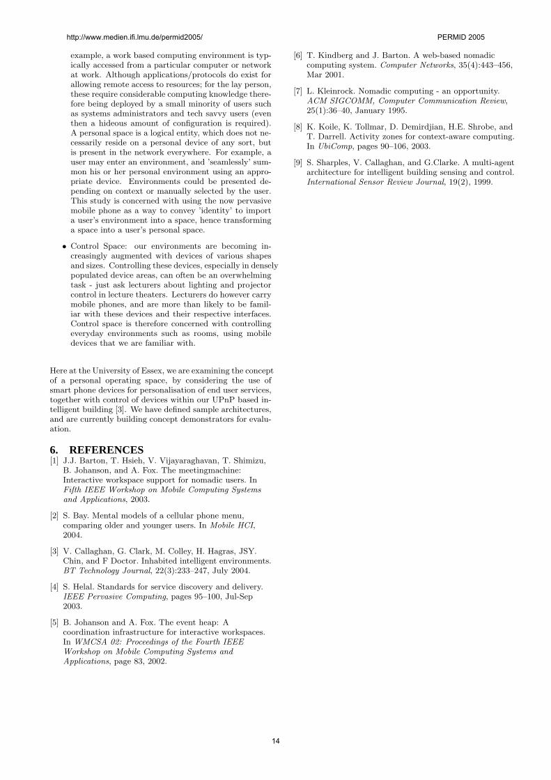
The virtual services component provides semantic descrip-tions of services discovered within a building. Semantic de-scriptions allow composition of services into complex work-flows, together with providing information about how theseservices may be presented to a space as ’Tasks’: figure 3
http://www.medien.ifi.lmu.de/permid2005/ PERMID 2005
11
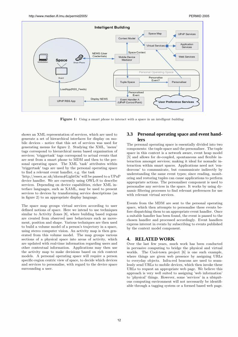
Figure 1: Using a smart phone to interact with a space in an intelligent building
shows an XML representation of services, which are used togenerate a set of hierarchical interfaces for display on mo-bile devices - notice that this set of services was used forgenerating menus for figure 2. Studying the XML, ’menu’tags correspond to hierarchical menu based organisation ofservices; ’triggertask’ tags correspond to actual events thatare sent from a smart phone to MDM and then to the per-sonal operating space. The XML ’task’ attributes within’triggertask’ tags are used by the personal operating spaceto find a relevant event handler, e.g. the task’http://essex.ac.uk/idorm#LightOn’ will be passed to a UPnPdevice handler. We are currently using OWL-S to describeservices. Depending on device capabilities, richer XML in-terface languages, such as XAML, may be used to presentservices to devices by transforming service descriptions (asin figure 2) to an appropriate display language.
The space map groups virtual services according to userdefined notions of space. Here we intend to use techniquessimilar to Activity Zones [8], where building based regionsare created from observed user behaviours such as move-ment, position and shape. Various techniques are then usedto build a volume model of a person’s trajectory in a space,using stereo computer vision. An activity map is then gen-erated from this volume model. The map groups varioussections of a physical space into areas of activity, whichare updated with real-time information regarding users andother contextual information. Applications may then usethe activity map to make decisions based on rich contextmodels. A personal operating space will require a personspecific-region centric view of space, to decide which devicesand services to personalise, with regard to the device spacesurrounding a user.
3.3 Personal operating space and event hand-lers
The personal operating space is essentially divided into twocomponents: the tuple space and the personaliser. The tuplespace in this context is a network aware, event heap model[5] and allows for de-coupled, spontaneous and flexible in-teraction amongst services; making it ideal for nomadic in-teraction within smart spaces. Applications need not ’ren-dezvous’ to communicate, but communicate indirectly byunderstanding the same event types; since reading, monit-oring and restoring tuples can cause applications to performappropriate actions. The personaliser component is used topersonalise any services in the space. It works by using dy-namic filtering processes to find relevant preferences for usewith relevant virtual services.
Events from the MDM are sent to the personal operatingspace, which then attempts to personalise these events be-fore dispatching them to an appropriate event handler. Oncea suitable handler has been found, the event is passed to thechosen handler and processed accordingly. Event handlersexpress interest in events by subscribing to events publishedby the context model component.
4. RELATED WORKOver the last few years, much work has been conductedin pervasive computing to bridge the physical and virtualworlds. The Cool-town project [6] is one such example,where things are given web presence by assigning URLsto everyday objects. Infra-red beacons are used to seam-lessly send URLs to mobile devices, which then invoke theseURLs to request an appropriate web page. We believe thisapproach is very well suited to assigning ’web information’to ’physical’ things. However, some ’services’ in a ubiquit-ous computing environment will not necessarily be identifi-able through a tagging system or a formed based web page.
http://www.medien.ifi.lmu.de/permid2005/ PERMID 2005
12
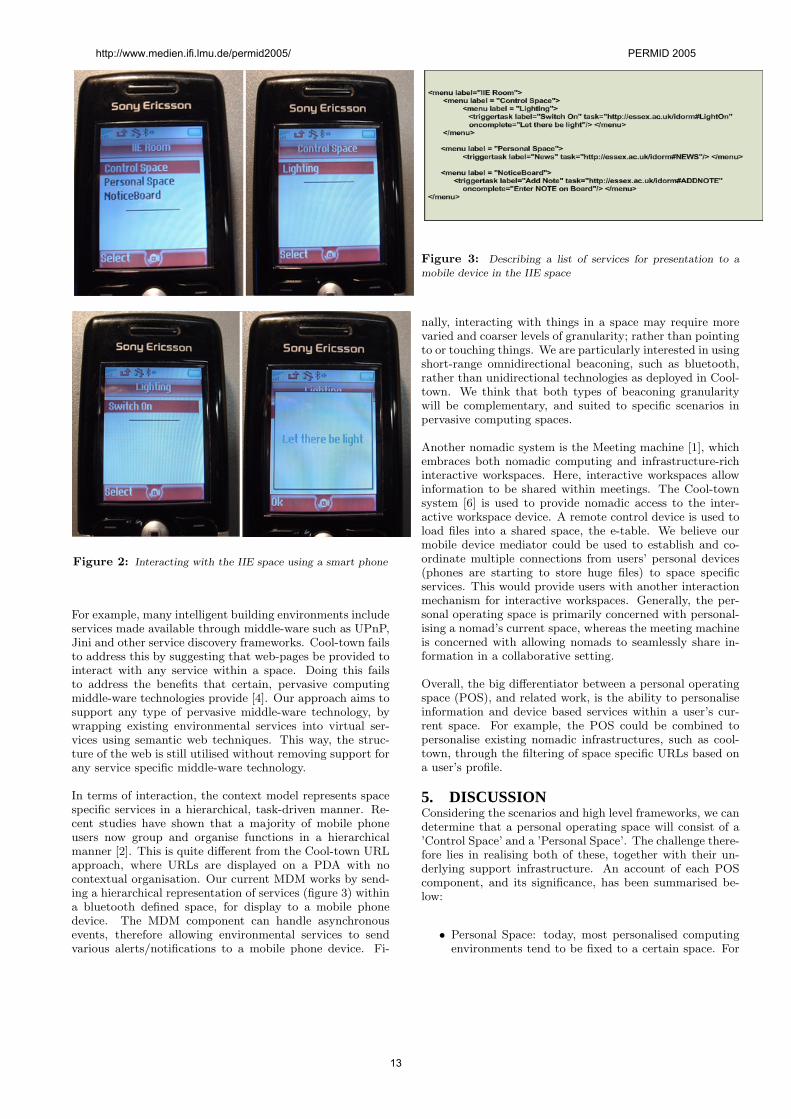
Figure 2: Interacting with the IIE space using a smart phone
For example, many intelligent building environments includeservices made available through middle-ware such as UPnP,Jini and other service discovery frameworks. Cool-town failsto address this by suggesting that web-pages be provided tointeract with any service within a space. Doing this failsto address the benefits that certain, pervasive computingmiddle-ware technologies provide [4]. Our approach aims tosupport any type of pervasive middle-ware technology, bywrapping existing environmental services into virtual ser-vices using semantic web techniques. This way, the struc-ture of the web is still utilised without removing support forany service specific middle-ware technology.
In terms of interaction, the context model represents spacespecific services in a hierarchical, task-driven manner. Re-cent studies have shown that a majority of mobile phoneusers now group and organise functions in a hierarchicalmanner [2]. This is quite different from the Cool-town URLapproach, where URLs are displayed on a PDA with nocontextual organisation. Our current MDM works by send-ing a hierarchical representation of services (figure 3) withina bluetooth defined space, for display to a mobile phonedevice. The MDM component can handle asynchronousevents, therefore allowing environmental services to sendvarious alerts/notifications to a mobile phone device. Fi-
Figure 3: Describing a list of services for presentation to a
mobile device in the IIE space
nally, interacting with things in a space may require morevaried and coarser levels of granularity; rather than pointingto or touching things. We are particularly interested in usingshort-range omnidirectional beaconing, such as bluetooth,rather than unidirectional technologies as deployed in Cool-town. We think that both types of beaconing granularitywill be complementary, and suited to specific scenarios inpervasive computing spaces.
Another nomadic system is the Meeting machine [1], whichembraces both nomadic computing and infrastructure-richinteractive workspaces. Here, interactive workspaces allowinformation to be shared within meetings. The Cool-townsystem [6] is used to provide nomadic access to the inter-active workspace device. A remote control device is used toload files into a shared space, the e-table. We believe ourmobile device mediator could be used to establish and co-ordinate multiple connections from users’ personal devices(phones are starting to store huge files) to space specificservices. This would provide users with another interactionmechanism for interactive workspaces. Generally, the per-sonal operating space is primarily concerned with personal-ising a nomad’s current space, whereas the meeting machineis concerned with allowing nomads to seamlessly share in-formation in a collaborative setting.
Overall, the big differentiator between a personal operatingspace (POS), and related work, is the ability to personaliseinformation and device based services within a user’s cur-rent space. For example, the POS could be combined topersonalise existing nomadic infrastructures, such as cool-town, through the filtering of space specific URLs based ona user’s profile.
5. DISCUSSIONConsidering the scenarios and high level frameworks, we candetermine that a personal operating space will consist of a’Control Space’ and a ’Personal Space’. The challenge there-fore lies in realising both of these, together with their un-derlying support infrastructure. An account of each POScomponent, and its significance, has been summarised be-low:
• Personal Space: today, most personalised computingenvironments tend to be fixed to a certain space. For
http://www.medien.ifi.lmu.de/permid2005/ PERMID 2005
13
example, a work based computing environment is typ-ically accessed from a particular computer or networkat work. Although applications/protocols do exist forallowing remote access to resources; for the lay person,these require considerable computing knowledge there-fore being deployed by a small minority of users suchas systems administrators and tech savvy users (eventhen a hideous amount of configuration is required).A personal space is a logical entity, which does not ne-cessarily reside on a personal device of any sort, butis present in the network everywhere. For example, auser may enter an environment, and ’seamlessly’ sum-mon his or her personal environment using an appro-priate device. Environments could be presented de-pending on context or manually selected by the user.This study is concerned with using the now pervasivemobile phone as a way to convey ’identity’ to importa user’s environment into a space, hence transforminga space into a user’s personal space.
• Control Space: our environments are becoming in-creasingly augmented with devices of various shapesand sizes. Controlling these devices, especially in denselypopulated device areas, can often be an overwhelmingtask - just ask lecturers about lighting and projectorcontrol in lecture theaters. Lecturers do however carrymobile phones, and are more than likely to be famil-iar with these devices and their respective interfaces.Control space is therefore concerned with controllingeveryday environments such as rooms, using mobiledevices that we are familiar with.
Here at the University of Essex, we are examining the conceptof a personal operating space, by considering the use ofsmart phone devices for personalisation of end user services,together with control of devices within our UPnP based in-telligent building [3]. We have defined sample architectures,and are currently building concept demonstrators for evalu-ation.
6. REFERENCES[1] J.J. Barton, T. Hsieh, V. Vijayaraghavan, T. Shimizu,
B. Johanson, and A. Fox. The meetingmachine:Interactive workspace support for nomadic users. InFifth IEEE Workshop on Mobile Computing Systemsand Applications, 2003.
[2] S. Bay. Mental models of a cellular phone menu,comparing older and younger users. In Mobile HCI,2004.
[3] V. Callaghan, G. Clark, M. Colley, H. Hagras, JSY.Chin, and F Doctor. Inhabited intelligent environments.BT Technology Journal, 22(3):233–247, July 2004.
[4] S. Helal. Standards for service discovery and delivery.IEEE Pervasive Computing, pages 95–100, Jul-Sep2003.
[5] B. Johanson and A. Fox. The event heap: Acoordination infrastructure for interactive workspaces.In WMCSA 02: Proceedings of the Fourth IEEEWorkshop on Mobile Computing Systems andApplications, page 83, 2002.
[6] T. Kindberg and J. Barton. A web-based nomadiccomputing system. Computer Networks, 35(4):443–456,Mar 2001.
[7] L. Kleinrock. Nomadic computing - an opportunity.ACM SIGCOMM, Computer Communication Review,25(1):36–40, January 1995.
[8] K. Koile, K. Tollmar, D. Demirdjian, H.E. Shrobe, andT. Darrell. Activity zones for context-aware computing.In UbiComp, pages 90–106, 2003.
[9] S. Sharples, V. Callaghan, and G.Clarke. A multi-agentarchitecture for intelligent building sensing and control.International Sensor Review Journal, 19(2), 1999.
http://www.medien.ifi.lmu.de/permid2005/ PERMID 2005
14
Product Reviews in Mobile Decision Aid Systems
Rene T.A. Wietsma∗
and Francesco RiccieCommerce and Tourism Research Laboratory, ITC-irst
Via Solteri n◦ 3838100 Trento (TN) Italy
{wietsma,ricci}@itc.it
http://ectrl.itc.it
ABSTRACTRecommender systems provide decision aid and informationfiltering functions that have a great potential application inthe mobile context. An aspect which has not been exten-sively exploited, in current recommender systems, are waysto better explain the recommendations, for instance, exploit-ing the opinion of users about the recommended products.In this paper we shall describe the foundations for a mo-bile product recommender system which incorporates bothstructured (supplier driven) product descriptions and moresubjective product knowledge, provided by users reviews.We think this type of recommendation technology could beespecially useful in the mobile context, where people musttake decisions in a rather short period of time, with a limitedavailability of product information, and with limited devicecapabilities.
KeywordsMobile decision tools, meta recommender systems, electronicword-of-mouth
1. INTRODUCTIONA recent article in the Wall Street Journal [15] points outsome success factors of travel blogs, i.e., websites where peo-ple can post their travel experience in the form of a review.This article indicates that people look for different ways toobtain and share more objective information about touristproducts. Where a popular travel broker may say: ”This isgreat” or ”Try this out”, the personal reviews are expectedto give a more nuanced view, supported by ratings and richmedia data (photos, video, etc.)
Providing users with relevant recommendation informationis a difficult task. In addition to the technical components,such as the user model representation and the algorithmsto generate recommendations, based on the user model, onehas to design an appropriate graphical interface. This mustinclude the functions required to support the user in thedecision process, and convince her about the appropriate-ness of the recommendations. In the mobile context thiscan be regarded as a challenging task. Users tend to limitthe interaction with the system for many reasons: connec-tion and data exchange costs, environmental disturbances(noise,light,etc.), parallel activities of the user (driving, trav-
∗Rene is affiliated with both ITC-irst and the University ofTwente, Enschede, The Netherlands.
elling, etc.). Besides these external influences, the deviceitself brings additional constraints, such as, small computa-tion capabilities and limited input and output modality.
Our research focuses on methodologies and techniques forimproving the user acceptance of product recommendationsand for explaining these recommendations in the mobile con-text. To achieve this, we have developed a new approachwhere both product descriptions and user reviews are incor-porated. We believe this approach, exploiting the hiddenknowledge inside the reviews, will bring to the user moreconfidence on the recommendations and better product un-derstanding. The products considered by this mobile rec-ommender system are hotels and tourism attractions.
A user reviews can be described as a subjective piece ofnon structured text describing the user’s product knowl-edge, experiences and opinions, typically also summarizedby a final product rating. This non structured content in-troduces a number of research challenges, regarding the ef-fectively usage of these reviews. In fact, sophisticated filter-ing and search techniques must be exploited to find relevantknowledge in product reviews. User opinions and productsreviews are not new in the web scenario. Many productadvise guides can be found on the Internet offering basicfunctionalities to find products, their specification and theuser reviews [1]. These sites can be classified as consumeropinion platforms, which incorporate ’word-of-mouth’ prin-ciples, and facilitating the exchange of product opinions be-tween non experts [9]. There are many different motivatorsfor these web sites [6, 9], but the most relevant for our re-search are: advice seeking and user involvement.
The innovative aspect of our approach is the incorporationof reviews in a structured way into the recommendation pro-cess. This means that we regard reviews as an alternativesource of recommendation information, in which one canfind product information, product experience and productpopularity from a user’s perspective. To exploit this kind ofinformation, we use information retrieval and recommenda-tion technologies [19]. Traditional systems, like Epinion [4],have not offered smart ways to incorporate user reviews inthe product recommendation yet.
This approach could be highly beneficial in the tourism con-text where the tourist experience is the travel main motiva-tion [20]. Products, or better said tourism services, lacks the
http://www.medien.ifi.lmu.de/permid2005/ PERMID 2005
15
feature of ”try-before-buy” or ”return in case the quality isbelow expectance”. This implies that (online) buying touristproducts involves a certain amount of risk, which could belowered by providing the user with a better product descrip-tion and recommendation explanation. Another aspect, isrelated to the fact that a user buys more an overall experi-ence [20, 5], rather than a single product. This experienceinvolves three phases: anticipation (before), consumption(during) and memory (after). Reviews could contribute tothe first and last phase by providing a way to gather infor-mation of similar travellers or to process the user own travelexperiences.
2. RECOMMENDER SYSTEMSRecommender systems are applications exploited in eCom-merce web sites to suggest products and provide to con-sumers information for facilitating the decision process [18].These systems offer personalized recommendations by in-corporating the user characteristics, in terms of a persistentor ephemeral user model, and product wishes in terms ofuser queries. These systems implicitly assume that the userwishes and constraints can be converted, by using appro-priate recommendation algorithms, in product recommen-dations. The recommendation algorithms either use knowl-edge of the domain, e.g., in content- or knowledge-basedfiltering approaches, or data about user’s past behavior, insocial filtering approaches.
The content based approach, filters the products accordingto the features specified by the user in a query [11]. Thisapproach is especially useful when the product can be de-scribed by an extensive set of features. The user can specifyher wishes either explicitly by providing product attributevalues or implicitly, for instance, criticizing products shownby the system. Social filtering or collaborative filtering ap-proaches can be described as technologies that try to mech-anize the ’word of mouth’ idea [8]. Here the recommenda-tions are based on product rates given by a group of similartasted people (neighborhood). Current research is mostlyfacing scalability issues and early-rater problems [16].
In our laboratory we have developed two recommender sys-tems to support the user in travel planning. For the preand post travel planning process, we have developed Nutk-ing, a web based recommender system. Nutking enablesthe selection of travel locations, activities and attractionsand supports the bundling of a personalized travel plan [12].For the on-tour support, we have developed a mobile appli-cation, MobyRek [13], that supports critique-based productrecommendations. In a critique-based recommender system,at every recommendation cycle, the user is allowed to criti-cize (i.e., to judge) the system’s recommendation result [14,3]. Both systems do not integrate reviews and, until now,we haven’t found any recommender system that integratesreviews in the way we propose.
3. REVIEWS IN MOBILE DECISION AIDSYSTEMS
3.1 ObjectivesThe overall objective of this research project is to design amethodology for mobile recommender systems that incor-porates different knowledge sources and offer better recom-
mendations in this context. The knowledge sources could bestructured or not. In the first case, we consider product cat-alogues, where products are described with feature vectors,that can be easily queried with standard query languages.In the second case, we consider product reviews reposito-ries, that are generated by a community of users interactingwith a web site. To extract knowledge from this kind ofrepositories we will use social-filtering algorithms.
This methodology includes the design of a recommendationarchitecture in which the above mentioned sources of knowl-edge can be integrated together exploiting the best filteringalgorithm for each available knowledge source. Some addi-tional objectives, which will be derived from an empiricalstudy, are the tuning parameters of each filtering algorithmand the approach for aggregating the results of the variousfiltering algorithms.
We aim at incorporating the previously mentioned hybridproduct recommendation approach in a mobile applicationthat users could access to obtain recommendations in a logi-cal and straightforward way. The application will supply theuser with additional functionalities (rank, sort and search)to revise the recommendations and better fit her wishes.Partly, these design principles will be derived from a userbehavior study.
Moreover, we aim at providing an improved explanation ofthe recommendation to the user. In fact, in the currentlyavailable systems, the user only receives the recommendedproduct together with an overall score indicating the ap-propriateness of such recommendation [7]. This kind of ex-planation is quite rudimentary and may raise doubts andquestions to the user. We think to improve this explanationby providing the relevant reviews of similar tasted users.Moreover we aim at increasing the product acceptance rate.In fact, in current systems, a user is only able to retrieve theinformation provided by the supplier. As discussed before,travel decision making must consider the risk the service willfail to satisfy the user. Hence, we want to minimize this risk,and we hypothesis that reviews can contribute to attain thisgoal [6].
3.2 The MethodologyTo convert our ideas into design principles, we have donea user behavior study in a group of 29 students. In thisstudy we investigated the usage of product descriptions andreviews in the booking process of two different types of prod-ucts: hotels and attractions. It is worth mentioning somedifferences found in the initial product filtering for the twoproduct types. Hotel filtering was, in general, based on spe-cific product features whereas for attractions people weremore biased by the reviews. Another interesting result isthe correlation between the perceived usefulness of productreviews and previous experience with product reviews websites. These people, with previous experience in such typeof content, where also more interested in negative reviews.
The design principles derived from this user behavior studytogether with our own ideas were incorporated into a sys-tem design. Since, one of the most important goal is toincorporate different knowledge sources we have adopted anmeta recommender system architecture [17]. A meta rec-
http://www.medien.ifi.lmu.de/permid2005/ PERMID 2005
16
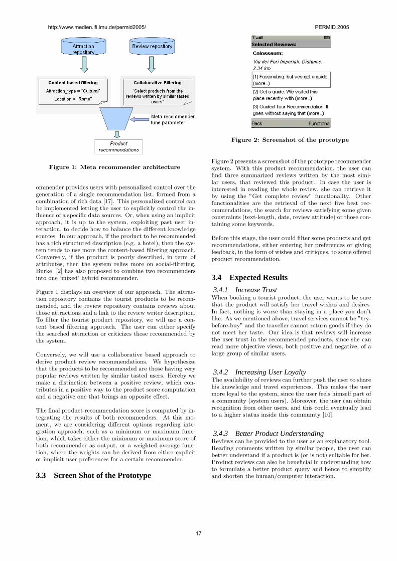
Figure 1: Meta recommender architecture
ommender provides users with personalized control over thegeneration of a single recommendation list, formed from acombination of rich data [17]. This personalized control canbe implemented letting the user to explicitly control the in-fluence of a specific data sources. Or, when using an implicitapproach, it is up to the system, exploiting past user in-teraction, to decide how to balance the different knowledgesources. In our approach, if the product to be recommendedhas a rich structured description (e.g. a hotel), then the sys-tem tends to use more the content-based filtering approach.Conversely, if the product is poorly described, in term ofattributes, then the system relies more on social-filtering.Burke [2] has also proposed to combine two recommendersinto one ’mixed’ hybrid recommender.
Figure 1 displays an overview of our approach. The attrac-tion repository contains the tourist products to be recom-mended, and the review repository contains reviews aboutthose attractions and a link to the review writer description.To filter the tourist product repository, we will use a con-tent based filtering approach. The user can either specifythe searched attraction or criticizes those recommended bythe system.
Conversely, we will use a collaborative based approach toderive product review recommendations. We hypothesizethat the products to be recommended are those having verypopular reviews written by similar tasted users. Hereby wemake a distinction between a positive review, which con-tributes in a positive way to the product score computationand a negative one that brings an opposite effect.
The final product recommendation score is computed by in-tegrating the results of both recommenders. At this mo-ment, we are considering different options regarding inte-gration approach, such as a minimum or maximum func-tion, which takes either the minimum or maximum score ofboth recommender as output, or a weighted average func-tion, where the weights can be derived from either explicitor implicit user preferences for a certain recommender.
3.3 Screen Shot of the Prototype
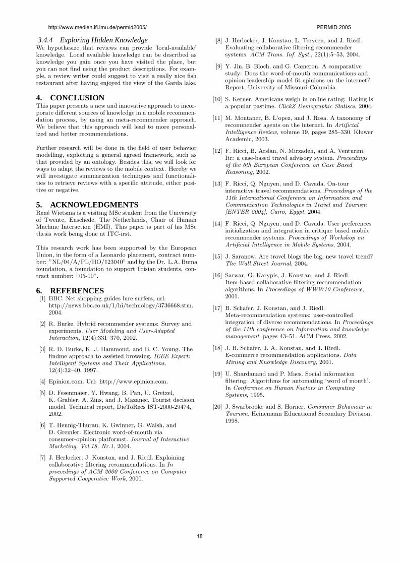
Figure 2: Screenshot of the prototype
Figure 2 presents a screenshot of the prototype recommendersystem. With this product recommendation, the user canfind three summarized reviews written by the most simi-lar users, that reviewed this product. In case the user isinterested in reading the whole review, she can retrieve itby using the ”Get complete review” functionality. Otherfunctionalities are the retrieval of the next five best rec-ommendations, the search for reviews satisfying some givenconstraints (text-length, date, review attitude) or those con-taining some keywords.
Before this stage, the user could filter some products and getrecommendations, either entering her preferences or givingfeedback, in the form of wishes and critiques, to some offeredproduct recommendation.
3.4 Expected Results
3.4.1 Increase TrustWhen booking a tourist product, the user wants to be surethat the product will satisfy her travel wishes and desires.In fact, nothing is worse than staying in a place you don’tlike. As we mentioned above, travel services cannot be ”try-before-buy” and the traveller cannot return goods if they donot meet her taste. Our idea is that reviews will increasethe user trust in the recommended products, since she canread more objective views, both positive and negative, of alarge group of similar users.
3.4.2 Increasing User LoyaltyThe availability of reviews can further push the user to sharehis knowledge and travel experiences. This makes the usermore loyal to the system, since the user feels himself part ofa community (system users). Moreover, the user can obtainrecognition from other users, and this could eventually leadto a higher status inside this community [10].
3.4.3 Better Product UnderstandingReviews can be provided to the user as an explanatory tool.Reading comments written by similar people, the user canbetter understand if a product is (or is not) suitable for her.Product reviews can also be beneficial in understanding howto formulate a better product query and hence to simplifyand shorten the human/computer interaction.
http://www.medien.ifi.lmu.de/permid2005/ PERMID 2005
17
3.4.4 Exploring Hidden KnowledgeWe hypothesize that reviews can provide ’local-available’knowledge. Local available knowledge can be described asknowledge you gain once you have visited the place, butyou can not find using the product descriptions. For exam-ple, a review writer could suggest to visit a really nice fishrestaurant after having enjoyed the view of the Garda lake.
4. CONCLUSIONThis paper presents a new and innovative approach to incor-porate different sources of knowledge in a mobile recommen-dation process, by using an meta-recommender approach.We believe that this approach will lead to more personal-ized and better recommendations.
Further research will be done in the field of user behaviormodelling, exploiting a general agreed framework, such asthat provided by an ontology. Besides this, we will look forways to adapt the reviews to the mobile context. Hereby wewill investigate summarization techniques and functionali-ties to retrieve reviews with a specific attitude, either posi-tive or negative.
5. ACKNOWLEDGMENTSRene Wietsma is a visiting MSc student from the Universityof Twente, Enschede, The Netherlands, Chair of HumanMachine Interaction (HMI). This paper is part of his MScthesis work being done at ITC-irst.
This research work has been supported by the EuropeanUnion, in the form of a Leonardo placement, contract num-ber: ”NL/04/A/PL/HO/123040” and by the Dr. L.A. Bumafoundation, a foundation to support Frisian students, con-tract number: ”05-10”.
6. REFERENCES[1] BBC. Net shopping guides lure surfers, url:
http://news.bbc.co.uk/1/hi/technology/3736668.stm.2004.
[2] R. Burke. Hybrid recommender systems: Survey andexperiments. User Modeling and User-AdaptedInteraction, 12(4):331–370, 2002.
[3] R. D. Burke, K. J. Hammond, and B. C. Young. Thefindme approach to assisted browsing. IEEE Expert:Intelligent Systems and Their Applications,12(4):32–40, 1997.
[4] Epinion.com. Url: http://www.epinion.com.
[5] D. Fesenmaier, Y. Hwang, B. Pan, U. Gretzel,K. Grabler, A. Zins, and J. Mazanec. Tourist decisionmodel. Technical report, DieToRecs IST-2000-29474,2002.
[6] T. Hennig-Thurau, K. Gwinner, G. Walsh, andD. Gremler. Electronic word-of-mouth viaconsumer-opinion platformst. Journal of InteractiveMarketing, Vol.18, Nr.1, 2004.
[7] J. Herlocker, J. Konstan, and J. Riedl. Explainingcollaborative filtering recommendations. In Inproceedings of ACM 2000 Conference on ComputerSupported Cooperative Work, 2000.
[8] J. Herlocker, J. Konstan, L. Terveen, and J. Riedl.Evaluating collaborative filtering recommendersystems. ACM Trans. Inf. Syst., 22(1):5–53, 2004.
[9] Y. Jin, B. Bloch, and G. Cameron. A comparativestudy: Does the word-of-mouth communications andopinion leadership model fit epinions on the internet?Report, University of Missouri-Columbia.
[10] S. Kerner. Americans weigh in online rating: Rating isa popular pastime. ClickZ Demographic Statiscs, 2004.
[11] M. Montaner, B. L’opez, and J. Rosa. A taxonomy ofrecommender agents on the internet. In ArtificialIntelligence Review, volume 19, pages 285–330. KluwerAcademic, 2003.
[12] F. Ricci, B. Arslan, N. Mirzadeh, and A. Venturini.Itr: a case-based travel advisory system. Proceedingsof the 6th European Conference on Case BasedReasoning, 2002.
[13] F. Ricci, Q. Nguyen, and D. Cavada. On-tourinteractive travel recommendations. Proceedings of the11th International Conference on Information andCommunication Technologies in Travel and Tourism[ENTER 2004], Cairo, Egypt, 2004.
[14] F. Ricci, Q. Nguyen, and D. Cavada. User preferencesinitialization and integration in critique based mobilerecommender systems. Proceedings of Workshop onArtificial Intelligence in Mobile Systems, 2004.
[15] J. Saranow. Are travel blogs the big, new travel trend?The Wall Street Journal, 2004.
[16] Sarwar, G. Karypis, J. Konstan, and J. Riedl.Item-based collaborative filtering recommendationalgorithms. In Proceedings of WWW10 Conference,2001.
[17] B. Schafer, J. Konstan, and J. Riedl.Meta-recommendation systems: user-controlledintegration of diverse recommendations. In Proceedingsof the 11th conference on Information and knowledgemanagement, pages 43–51. ACM Press, 2002.
[18] J. B. Schafer, J. A. Konstan, and J. Riedl.E-commerce recommendation applications. DataMining and Knowledge Discovery, 2001.
[19] U. Shardanand and P. Maes. Social informationfiltering: Algorithms for automating ‘word of mouth’.In Conference on Human Factors in ComputingSystems, 1995.
[20] J. Swarbrooke and S. Horner. Consumer Behaviour inTourism. Heinemann Educational Secondary Division,1998.
http://www.medien.ifi.lmu.de/permid2005/ PERMID 2005
18
Service Discovery in TinyObj: Strategies and Approaches Pavel Poupyrev, Takahiro Sasao, Shunsuke Saruwatari,
Hiroyuki Morikawa, Tomonori Aoyama The Graduate School of Frontier Science, Tokyo University
7-3-1 Hongo, Bunkyo-ku, Tokyo, 113-8656 Japan
{pavel, sasao, saru, mori, aoyama}@mlab.t.u-tokyo.ac.jp
Peter Davis
Adaptive Communications Research Laboratories, ATR
2-2-2 Hikaridai, "Keihanna Science City" Kyoto, 619-0288 Japan
ABSTRACT In this paper, we describe TinyObj service discovery model, which uses short wireless packet broadcasts for service discovery within a user’s vicinity. We present a prototype implementation for the discovery model including the hardware and software development of a wireless discovery device. The developed wireless device, called Buoy, can be used as an independent service discovery device or as an attachment for cellular phones. The aim of the design is to provide the basic functionality for service discovery in ubiquitous environment. The developed software includes a uniform user interface that makes the system expandable and customizable. Indeed, a user can easily add, advertise, discover and remove any services in the system.
1. INTRODUCTION Discovery of information is an essential problem in our daily lives. One of the easiest ways of finding information is using an Internet search engine that replies to user’s queries with global search results. However, this way of information discovery provides little connectivity with the user’s surrounding world since the search is conducted over a worldwide information database.
A new discipline, called ubiquitous computing, has been proposed [1-2]. Ubiquitous computing provides to a user a better connection with its surrounding world. In fact, this is achieved by embedding small computing devices in every object of the physical world. These devices can be equipped with short range wireless modules making the discovery of other devices and their services accessible to a user. We define this discovery as a real-world service discovery in proximity.
The real-world service discovery in proximity is different from the conventional ways of discovering services. Currently, a user discovers services upon request on the Internet or using other media such as newspapers. However, discovery in ubiquitous environment is performed in the background. Indeed, a user discovers services while moving from one place to another. This allows a user to find services in new locations or even newly advertised services in common visited places. The real-world discovery very well fits with the concept of ubiquitous computing where a user interacts with the real-world using background wireless computing devices.
A good example of a real-world service discovery in ubiquitous environment is the discovery of an ATM service. In this scenario, a user wants to find an ATM that belongs to a particular bank or provides VISA credit card operations. In order to do that a user has to define the ATM service discovery preferences specifying
discovery details such as the bank name. When a user comes in proximity of an ATM, the user’s device discovers the presence of the ATM. If a discovered ATM matches the specified preferences then the device alerts the user about its discovery.
The main contribution of this paper is the proposal of the TinyObj model for real-world service discovery in a ubiquitous environment and its prototype implementation. Since wireless ubiquitous devices have scarce resources, such as battery and processing power, we use a broadcast protocol eliminating the necessity for a complex routing protocol.
The prototype implementation has been developed including both software and hardware modules. We developed a wireless device for service discovery that can be used as an attachment with cellular phones or as an independent wireless discovery device. The developed discovery device is based on an original CSMA/CA-based MAC protocol.. The designed software provides to a user the ability of adding, advertising, discovering and removing new services using a uniform graphical user interface, unlike other discovery systems, which require knowledge of a programming language.
We will describe our prototype implementation covering three elements of the system:
Service matchmaking: The number of provided services usually greatly exceeds the number of services a user needs. The system should provide a mechanism for receiving focused search results. Also, service matchmaking should have a general way to represent any service. A user should be able to easily add and remove services from the system.
User Interaction: Our service discovery is meant to support two types of mobile users: a user with a cellular phone and a user with a wireless discovery device. One of the requirements is to provide easy user interaction with the device for both types of users.
Broadcast Protocol: Broadcasting is an important component of the system and should provide efficient data dissemination and consume as less power as possible. In this paper, we only discuss the requirements for the broadcast protocol.
The rest of the paper is organized as follows: In the next section we will present related works followed by an explanation about the TinyObj discovery model. In section 4 we will explain our implementation prototype, covering three major service discovery elements: service matchmaking, user interaction and network protocol approaches. In the last section we will conclude our work and describe directions for future work.
http://www.medien.ifi.lmu.de/permid2005/ PERMID 2005
19
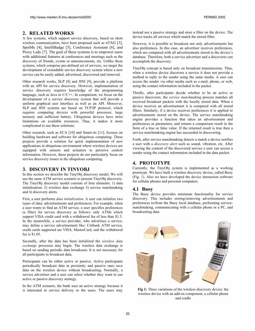
Fig 1: Three variations of the wireless discovery device: the wireless device with an add-on component, a cellular phone
and cradle
2. RELATED WORKS A few systems, which support service discovery, based on short wireless communication, have been proposed such as nTAG [3], SpotMe [4], IntelliBadge [5], Conference Assistant [6], and Proxy Lady [7]. The goal of these systems is to empower users with additional features at conferences and meetings such as the discovery of friends, events or announcements, etc. Unlike these systems, which comprise pre-defined set of services, we target the development of extendable service discovery system where a new service can be easily added, advertised, discovered and removed.
Other research works, SLP [8] and JINI [9], provide a platform with an API for service discovery. However, implementation of service discovery requires knowledge of the programming language, such as Java or C/C++. In comparison, we focus on the development of a service discovery system that will provide a uniform graphical user interface as well as an API. Moreover, SLP and JINI systems are based on TCP/IP protocol, which requires computing devices with powerful processor, large memory and sufficient battery. Ubiquitous devices have strict limitations on available resources. Thus, it makes it more complicated to use these solutions.
Other research, such as ECA [10] and Smart-its [11], focuses on building hardware and software for ubiquitous computing. These projects provide a solution for quick implementation of new applications in ubiquitous environment where wireless devices are equipped with sensors and actuators to perceive context information. However, these projects do not particularly focus on service discovery issues in the ubiquitous computing.
3. DISCOVERY IN TINYOBJ In this section we describe the TinyObj discovery model. We will use the same ATM service scenario to present TinyObj discovery. The TinyObj discovery model consists of four elements: 1) data initialization; 2) wireless data exchange 3) service matchmaking and 4) discovery alerts.
First, a user performs data initialization. A user can initialize two types of data: advertisements and preferences. For example, when a user wants to find an ATM service, a user specifies preferences (a filter) for service discovery as follows: only ATMs which support VISA credit card with a withdrawal fee of less than $1.5. In the meanwhile, a service provider, who advertises a service, may define a service advertisement like: Citibank ATM service, credit cards supported are VISA, MasterCard, and the withdrawal fee is $1.05.
Secondly, after the data has been initialized the wireless data exchange processes may begin. The wireless data exchange is based on sending periodic data broadcasts. It is not necessary for all participants to broadcast data.
Participants can be either active or passive. Active participants periodically broadcast data in proximity and passive ones save data on the wireless device without broadcasting. Normally, a service advertiser and a user can select whether they want to use active or passive discovery strategy.
In the ATM scenario, the bank uses an active strategy because it is interested in service delivery to the users. The users may
instead use a passive strategy and store a filter on the device. The device tracks all services which match the stored filter.
However, it is possible to broadcast not only advertisements but also preferences. In this case, an advertiser receives preferences, which are compared with all advertisements stored in the device’s database. Therefore, both a service advertiser and a discoverer can accomplish the discovery.
TinyObj concept is based only on broadcast transmissions. Thus, when a wireless device discovers a service it does not provide a method to reply to the sender using the same media. A user can access the sender via other media such as e-mail, phone, or web, using the contact information included in the packet.
Thirdly, after participants decide whether to be an active or passive discoverer, the service matchmaking process matches all received broadcast packets with the locally stored data. When a device receives an advertisement it is compared with all stored filters. Similarly, if a device receives preferences it is applied to advertisements stored on the device. The service matchmaking engine provides a function that takes an advertisement and preferences as parameters, and returns a comparison result in the form of a true or false value. If the returned result is true then a service matchmaking engine has succeeded in discovering.
Forth, after service matchmaking detects a match a device notifies a user with a discovery alert such as sound, vibration, etc. After viewing the content of the discovered service a user can access a sender using the contact information included in the data packet.
4. PROTOTYPE Currently, the TinyObj system is implemented as a working prototype. We have built a wireless discovery device, called Buoy (Fig. 1). Also we have developed the device interaction software for cellular phones and personal computers.
4.1 Buoy The Buoy device provides minimum functionality for service discovery. This includes storing/removing advertisements and preferences to/from the Buoy local database, performing service-matchmaking, communicating with a cellular phone or a PC, and broadcasting data.
http://www.medien.ifi.lmu.de/permid2005/ PERMID 2005
20
Service name: ATM Category: Finance Bank Description: ATM service discovery Attribute
Name Type Default
Value Displa
y Required
Bank name String VISA, Master, Plus Credit cards Select Availability Select Open, Closed Charge fee Currency Location String
Fig 3: A service descriptor example for an ATM service
a) b)
Fig 4: A cellular phone screen shots of TinyObj application a) a list of services registered with cellular phone b) an ATM
service filter creation Fig 2: Buoy device schematics
The discovery wireless device consists of two components namely a wireless module and an add-on component (Fig. 2). The wireless module includes the following components: a battery, an antenna, an Atmel ATmega128L processor, a Chipcon CC1000 wireless module, and two serial interfaces where one can be used by a cradle and another can be used by a cellular phone. The add-on component connects to the wireless module to provide a primitive input/output user interface equipped with a buzzer, two LEDs, a button and an Infrared port. The dimension of the device is 62x40x15mm.
4.2 Service Matchmaking The service matchmaking is a vital component for successful discovery. The service matchmaking defines a format for service data and provides an algorithm for comparing advertisements and preferences. The format includes a list of name-value attributes to describe the service. This format enables the creation of services. However, our proposed system does not provide any access methods to the service but provides only service availability information. For example, if a user discovers a printer service, it may contain an IP address that can be used to reach the printer. The service matchmaking algorithm should provide narrowed search results because it is important to minimize the number of false alerts. For example, in an ATM service scenario, a user wants to discover ATM services satisfying some search preferences.
The system uses a service descriptor (Fig.3) that serves as a template to define advertisements and preferences. Also, the service descriptor includes information so that the TinyObj software knows how to represent data in a common way.
Fig. 3 shows an example of a service descriptor for an ATM service. The general parameters for a service descriptor are a service name, a description and a category. Attributes are optional parameters, which allow a user to provide more detailed information about a service. The attributes are useful for narrowing search results since they can specify search preferences more precisely. An attribute includes a name, a type, default values, a display and required options.
The type defines a data format used by the software to verify data input correctness and to represent the data. The type can be selected from the available types. The supported types in the current implementation are: Integer, Currency, Boolean, Select,
and String types. The default value provides initial values when a new advertisement or filter is created.
A display option is used by the software for partial representation of advertisements. For example, Fig. 4a represents a list of discovered advertisements. Two ATM advertisements, Citibank and Mizuho, have partial representation depicting only three attributes: Bank name, Availability and Charge fee. In this case, TinyObj software represents only attributes, which have the display option enabled in the service descriptor.
Thus, each service has a service descriptor that serves as a template for the creation of advertisements or preferences. TinyObj software allows a user to create a new service descriptor using a graphical user interface specifying a service name, a category, a description and a list of attributes.
4.3 User Interactions The TinyObj system is designed mainly for two types of users: a cellular phone user and a user that uses only the Buoy device without attaching it to a cellular phone. In this section we will describe interaction for both types of users.
4.3.1 Cellular phone user interaction In Fig. 1, the Buoy wireless module is attached to a cellular phone. In order to advertise or discover a service, a user first has to store a service descriptor on the Buoy device so that the Buoy software knows how to handle a service. In the current version of the TinyObj prototype, all created service descriptors are stored in the web-enabled database. A user can search for a necessary service descriptor using keyword searches or category searches. After discovery of the service descriptor a user can create
http://www.medien.ifi.lmu.de/permid2005/ PERMID 2005
21
advertisements or preferences. When using service descriptors, the software can represent a form to assist the user in the creation of an advertisement or preferences. For example, Fig. 4b represents the case when a user creates a filter for discovering any ATM services that belongs to Citibank. After inputting the data, the user then specifies whether to choose an active or passive discovery mode. Finally, a user uploads and stores the input data and the service descriptor. Uploading a service descriptor is necessary if a user wants to create or edit the data later. Fig. 4a represents an example of stored service descriptors on the Buoy device including Friends, ATM and Music. After all these steps, a user is able to start discovering. When a new service is discovered, the phone alerts the user through sound or vibration depending on the phone’s settings.
4.3.2 Buoy device user interaction A user who does not have a cellular phone is still able to discover services in proximity using only Buoy. However, the interaction requires an additional device, such as a PC or a cellular phone, only when initializing data or viewing discovered services. The actual discovery does not require the use of any extra device. Buoy consists of two modules (Fig. 2): a wireless module and an add-on component. The add-on component has a primitive input/output interface with two LEDs, a button and a buzzer. Since the interface is very limited the use of an extra device becomes necessary in order to initialize the device as well as to view the discovered data. A user is provided with web-enabled PC software that can be accessed from the Internet. To initialize and view data with a computer, the Buoy uses the Infrared port.. Thus, the user interaction with Buoy works as follows. First, a user, using the web-enabled PC software, searches for a service descriptor. After finding the necessary service descriptor, a user creates an advertisement or a filter based on its content. Then, a user specifies whether to use active or passive discovery. Unlike cellular phone user interaction, a user selects an alert, such as flashing LEDs or a buzzer sound, for discovery notifications. Finally, a user uploads and stores these settings on Buoy using the Infrared port interface. When Buoy discovers an advertisement, it notifies a user with the predefined alert associated with the service so that a user knows which type of service has been discovered. In order to view the discovered data a user has to use a desktop PC or a cellular phone.
4.4 Broadcast protocol The TinyObj model is based on a broadcast packet exchange. Broadcast packets can be received by all neighboring nodes, which are in range of the transmitter. In our system the broadcast protocol does not provide a two-way communication scheme like usual routing protocols based on the query/reply model. This model has been selected to overcome the complexity and the limited scalability of typical packet routing protocol implementation especially in the case of highly dynamic mobile networks.
Broadcasting is a simple protocol that can be easily tuned to the application requirements. We define two requirements for our broadcast protocol, which are: 1) efficient packet dissemination and 2) minimization of power consumption. Efficient packet broadcasting is necessary because with the increase in the number of broadcasts the collision rate increases that leads to a poor
packet delivery rate. The current prototype is based on CSMA/CA protocol that consumes large amount of power while listening to a channel. If we assume a constant current drainage of 110 mAh, the battery would last for approximately 6 hours.
5. CONCLUSIONS AND FUTURE WORK In this paper, we described TinyObj service discovery model, which uses short wireless packet broadcasts for service discovery within a user’s vicinity. The broadcasting provides a simple way for data exchanges. We have presented a prototype implementation of the TinyObj model including both the software and the hardware. The hardware comprises the Buoy device that provides minimum functionality for service discovery. We also described user interactions with the Buoy device. The TinyObj software has been designed in order to provide a uniform graphical interface so that a user can easily add, remove, advertise and discover new services.
Future work would include studies on the implementation of power-efficient broadcast protocol and power-saving mechanisms. Moreover, the user interactions with the service discovery software should be improved to provide a generic platform. In order to do so, we are planning to conduct scenario field studies, adding new features to the system required by the different scenarios.
6. REFERENCES [1] Mark Weiser, "Hot Topics: Ubiquitous Computing" IEEE
Computer, October 1993. [2] Mark Weiser, "Some Computer Science Problems in
Ubiquitous Computing," Communications of the ACM, July 1993.
[3] http://www.ntag.com/, 2005 [4] http://www.spotme.ch/, 2005 [5] Donna Cox, Volodymyr Kindratenko, and David Pointer,
“IntelliBadge™: Towards Providing Location-Aware Value-Added Services at Academic Conferences,” in UbiComp 2003, Seattle, WA, USA.
[6] Anind K. Dey, Daniel Salber, Gregory D. Abowd and Masayasu Futakawa, “The Conference Assistant: Combining Context-Awareness with Wearable Computing,” In 3rd International Symposium on Wearable Computers, 1999.
[7] Per Dahlberg, Fredrik Ljungberg, and Johan Sanneblad, “Supporting Opportunistic Communication in Mobile Settings,” in CHI 2000 Extended Abstracts on Human Factors in Computing Systems, 2000.
[8] Guttman E., Perkins C. and Kaplan S., “Service Location Protocol,” RFC 2608
[9] Edwards W. K., “Core Jini,” Prentice-Hall, 2001. [10] Tsutomu Terada, Masahiko Tsukamoto, Keisuke Hayakawa,
Tomoki Yoshihisa, Yasue Kishino, Atsushi Kashitani, and Shojiro Nishio, “Ubiquitous Chip: A Rule-Based I/O Control Device for Ubiquitous Computing,” Pervasive 2004, pp. 238-253, 2004
[11] M. Beigl, and H. Gellersen, “Smart-its: An Embedded Platform for Smart Objects,” Smart Objects Conference (sOc), 2003.
http://www.medien.ifi.lmu.de/permid2005/ PERMID 2005
22
Camera Phones with Pen Input as Annotation Devices
Michael RohsInstitute for Pervasive ComputingDepartment of Computer Science
ETH Zurich, Switzerland
Christof RodunerInstitute for Pervasive ComputingDepartment of Computer Science
ETH Zurich, Switzerland
ABSTRACTThis paper explores the use of camera phones with pen in-put as a platform for generating digital annotations to real-world objects. We analyze the client-side requirements fora general annotation system that is applicable in mobileas well as stationary settings. We outline ways to createand interact with digital annotations using the camera andpen-based input. Two prototypically implemented anno-tation techniques are presented. The first technique usesvisual markers for digital annotations of individual itemsin printed photos. The second technique addresses the an-notation of street signs and indication panels. It is basedon image matching supported by interactively established4-point correspondences.
1. INTRODUCTIONDigital annotations link user-generated digital media to phys-ical objects. This allows users to combine the persistencyand availability of physical objects with the flexibility andversatility of digital media. Physical media, like printedphotographs and street signs, are tangible and permanent,but can typically store only a limited amount and type ofinformation. Digital media, like text, graphics, audio, andvideo, are immaterial and volatile, but are virtually unlim-ited in terms of the amount and type of information theycan represent. They can be automatically processed andshared across space and time. Using physical media as “en-try points” [11] to digital annotations is a way to structureinformation and to embed it into the real world. In compari-son to other types of augmentation the distinct feature of an-notations is that users can freely create them and that theyare not predefined by the system or any content provider.
Many projects have looked into annotating physical mediawith online information and services [2, 6, 7, 9, 11, 13, 14,15]. Our goal in this paper is to explore the interactionpossibilities of camera phones (or camera-equipped PDAs)with pen-based input as a platform for generating digitalannotations. We present ideas of how to create and interactwith annotations using phonecam-specific features. Moregenerally, we are interested in how a mobile user interface fora generic annotation system could be structured that allowsfor the creation, access, sharing, and organization of digitalannotations. This system shall be usable in stationary andmobile settings and exclusively rely on mobile devices asuser interfaces.
Camera phones fulfill several essential requirements of a
mobile annotation device. First, the camera in combina-tion with image processing algorithms allows for identifyingannotatable objects and for determining their orientation.There are multiple options for visually identifying physicalobjects, including image recognition techniques and visualmarker detection. RFID tagging and near-field communi-cation (NFC) for mobile devices [8] offer non-visual alter-natives. Determining the orientation of objects in the cam-era image enables the registration of graphical overlays inthe camera image in the sense of augmented reality [1, 4].Second, wireless connectivity allows for sharing annotationswith others, persistently storing and organizing them on aback-end server, and getting up-to-date information. Third,camera phones combine the ability to create annotations inmultiple media types with the ability to play them back.Fourth, they are ubiquitously available in users’ everydaysituations.
A distinct feature of pen-based input devices is that theyenable users to make more fine-grained annotations of ob-jects captured with the camera. Users can encircle objectsand create specific annotations to them, draw arrows to givedirections, or put predefined icons onto the captured image.In addition to allowing for more fine-grained annotations,pen-input can also support image processing algorithms bytelling the system which objects are relevant and which onesare not. In section 3 we show how this can be used to accu-rately segment street signs in images from the background.
Digital annotations can take many forms, such as text, graph-ics, audio, video, hyperlinks, vCard and vCalendar items,drawings and predefined graphical objects on the capturedimage. All of these media types can be created and pre-sented on camera phones. If the semantics of the annotatedobject or its classification in a taxonomy are known to thesystem, then users might be provided with forms for rat-ing objects or widgets for entering specific parameters. Thissupports users in minimizing the amount of data they haveto enter into their mobile device in order to create an annota-tion. Annotations can further be supported by context datathat is automatically gathered from the mobile phone [3],such as the current location or the time of day.
In section 2 we discuss the annotation of physical mediawith visual codes [10] in stationary settings. In section 3 wediscuss the annotation of signs – or other areas with fourclearly distinguishable corners – in outdoor environments,where attaching visual markers might not always be feasible.
http://www.medien.ifi.lmu.de/permid2005/ PERMID 2005
23
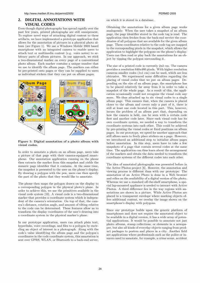
2. DIGITAL ANNOTATIONS WITHVISUAL CODES
Even though digital photography has spread rapidly over thepast few years, printed photographs are still omnipresent.To explore novel ways of attaching digital content to theseartifacts, we have implemented a prototype application thatallows for the annotation of pictures in a physical photo al-bum (see Figure 1). We use a Windows Mobile 2003 basedsmartphone with an integrated camera to enable users toattach text or multimedia content (e.g. voice notes) to ar-bitrary parts of album pictures. In our approach, we sticka two-dimensional marker on every page of a conventionalphoto album. Each marker contains a unique number thatwe use to identify the album page. The markers can eitherbe pre-printed onto pages or they can be supplied to usersas individual stickers that they can put on album pages.
Album Page Album Page
Figure 1: Digital annotation of a photo album withvisual codes.
In order to annotate a photo on an album page, users takea picture of that page with their camera-equipped smart-phone. Our annotation application running on the phonethen extracts the marker from this snapshot and yields thenumeric page identifier that it contains. At the same time,the snapshot is presented to the user on the phone’s display.By drawing a polygon with the pen, users can then specifythe part of the photo that they would like to annotate.
The phone then maps the polygon drawn on the display toa corresponding polygon in the physical photo’s plane. Inorder to achieve this, we use the primitives available in thevisual code system [10]. A visual code is a two-dimensionalmarker that provides a coordinate system which is indepen-dent of the camera’s orientation. On top of that, the cam-era’s distance, rotation angle, and amount of tilting relativeto the code can be determined. These features allow us totransform the display coordinates of the user’s drawing intoa coordinate system in the physical marker’s plane.
In our prototype application, users can attach plain text,hyperlinks, voice recordings, and files to a polygon by encir-cling an object of interest in a photograph. Along with thecode’s value identifying the album page and the polygon’scoordinates in the code coordinate system, this annotation issent over GPRS, WLAN, or Bluetooth to a back-end server,
on which it is stored in a database.
Obtaining the annotations for a given album page worksanalogously: When the user takes a snapshot of an albumpage, the page identifier stored in the code tag is read. Theapplication then fetches from the back-end service the coor-dinates of all polygons that are available for the given albumpage. These coordinates relative to the code tag are mappedto the corresponding pixels in the snapshot, which allows theapplication to highlight the polygons on the phone’s display.Users can then read or play back the annotations for an ob-ject by tipping the polygon surrounding it.
The size of a printed code is currently 2x2 cm. The cameraprovides a resolution 640x480 pixels. With higher resolutioncameras smaller codes (1x1 cm) can be used, which are lessobtrusive. We experienced some difficulties regarding theplacing of visual codes that we put on album pages. De-pending on the size of an album page, the smartphone hasto be placed relatively far away from it in order to take asnapshot of the whole page. As a result of this, the appli-cation occasionally could not recognize the visual code anymore. We thus attached up to six visual codes to a singlealbum page. This ensures that, when the camera is placedcloser to the album and covers only a part of it, there isstill at least one code located in this part. This, however,incurs the problem of an album part that, depending onhow the camera is held, can be seen with a certain codefirst and another code later. Since each visual code has itsown coordinate system, we needed a way to transform thecoordinate systems into each other. This could be achievedby pre-printing the visual codes at fixed positions on albumpages. In our prototype, we opted for another approach thatstill allows users to freely place stickers on a page. However,we introduced an additional step to initialize album pagesbefore annotation. In this step, users have to take a fewsnapshots of a page that contain several codes at the sametime. The application can thus learn about the arrangementof the markers and obtain the data needed to transform thecoordinate systems of the different codes into each other.
The idea of annotated photographs was presented before inthe Active Photos project [6]. However, the annotation andviewing process is different than with our prototype: Theannotation of an Active Photo is done in a Web browserand relies on the availability of a digital version of the photo.Whereas we use a standard off-the-shelf smartphone, a spe-cial lap-mounted appliance is needed to interact with ActivePhotos. A third difference lies in the way regions with an-notations are shown in a picture. While Active Photos areplaced in a transparent envelope where marking objects of-fers additional content, we overlay the image shown on thesmartphone’s display with polygons.
Since our prototype builds upon the generic platform ofsmartphones and does not require the annotated object tobe available in a digital version, it has a wide array of poten-tial applications. It would be possible to annotate not justphoto albums, stamp collections, or elements in a newspa-per, but also all kinds of everyday objects ranging from prod-uct packages to posters and places in a city. Another fieldare applications where professionals such as the police or in-surers need to annotate, for example, a crime scene, accident
http://www.medien.ifi.lmu.de/permid2005/ PERMID 2005
24
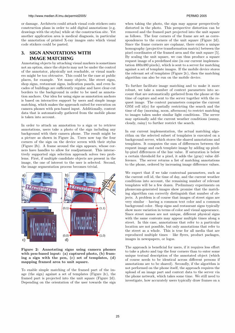
or damage. Architects could attach visual code stickers ontoconstruction plans in order to add digital annotations (e.g.drawings with the stylus) while at the construction site. Yetanother application area is medical diagnosis, in particularthe annotation of printed X-ray images onto which visualcode stickers could be pasted.
3. SIGN ANNOTATIONS WITHIMAGE MATCHING
Annotating objects by attaching visual markers is sometimesnot an option, since the objects may not be under the controlof the annotator, physically not reachable, or visual mark-ers might be too obtrusive. This could be the case at publicplaces, for example. Yet many objects, like street signs,shop signs, restaurant signs, indication panels, and even fa-cades of buildings are sufficiently regular and have clear-cutborders to the background in order to be used as annota-tion anchors. Our idea for using signs as annotation anchorsis based on interactive support by users and simple imagematching, which makes the approach suited for execution oncamera phones with pen-based input. Additionally, contextdata that is automatically gathered from the mobile phoneis taken into account.
In order to attach an annotation to a sign or to retrieveannotations, users take a photo of the sign including anybackground with their camera phone. The result might bea picture as shown in Figure 2a. Users now tap the fourcorners of the sign on the device screen with their stylus(Figure 2b). A frame around the sign appears, whose cor-ners have handles to allow for readjustment. This interac-tively supported sign selection approach solves two prob-lems. First, if multiple candidate objects are present in theimage, the one of interest to the user is selected. Second,the image segmentation process becomes trivial.
(1,1)
(1,0)
(0,1)
(0,0)
a) b)
c) d)
Figure 2: Annotating signs using camera phoneswith pen-based input: (a) captured photo, (b) fram-ing a sign with the pen, (c) set of templates, (d)mapping framed area to unit square.
To enable simple matching of the framed part of the im-age (the sign) against a set of templates (Figure 2c), theframed part is projected into the unit square (Figure 2d).Depending on the orientation of the user towards the sign
when taking the photo, the sign may appear perspectivelydistorted in the photo. This perspective distortion can beremoved and the framed part projected into the unit squareas follows. The four corners of the frame are set as corre-spondences to the corners of the unit square (Figure 2d).Since the frame corners are coplanar, there exists a uniquehomography (projective transformation matrix) between thepixel coordinates of the framed area and the unit square [5].By scaling the unit square, we can thus produce a squarerequest image of a predefined size (in our current implemen-tation 480x480 pixels), which is sent to a server for matchingagainst a set of template images. If the mobile device storesthe relevant set of templates (Figure 2c), then the matchingalgorithm can also be run on the mobile device.
To further facilitate image matching and to make it morerobust, we take a number of context parameters into ac-count that are automatically gathered from the phone at thetime of capture and sent to the server together with the re-quest image. The context parameters comprise the currentGSM cell id(s) for spatially restricting the search and thetime of day (morning, noon, afternoon) to restrict matchingto images taken under similar light conditions. The servermay optionally add the current weather conditions (sunny,cloudy, rainy) to further restrict the search.
In our current implementation, the actual matching algo-rithm on the selected subset of templates is executed on abackground server, which stores the shared annotations andtemplates. It computes the sum of differences between therequest image and each template image by adding up pixel-by-pixel differences of the hue value. If saturation is belowa certain threshold for a pixel, it adds the (gray) value dif-ference. The server returns a list of matching annotationsto the phone, ordered by increasing image difference values.
We expect that if we take contextual parameters, such asthe current cell id, the time of day, and the current weatherconditions into account, the remaining number of relevanttemplates will be a few dozen. Preliminary experiments onphonecam-generated images show promise that the match-ing algorithm can correctly distinguish that number of ob-jects. A problem is of course that images of street signs arevery similar – having a common text color and a commonbackground color. Shop signs and restaurant signs typicallyshow more variation in terms of color and visual appearance.Since street names are not unique, different physical signswith the same contents may appear multiple times along astreet. In this case, annotations that refer to a particularlocation are not possible, but only annotations that refer tothe street as a whole. This is true for all media that arereproduced multiple times – like flyers, product packages,images in newspapers, or logos.
The approach is beneficial for users, if it requires less effortto take a photo and tap the four corners than to enter someunique textual description of the annotated object (whichof course needs to be identical across different persons ifannotations are to be shared). Secondly, if the algorithm isnot performed on the phone itself, the approach requires theupload of an image part and context data to the server viathe phone network, which takes some time. We still need toinvestigate, how accurately users typically draw frames on a
http://www.medien.ifi.lmu.de/permid2005/ PERMID 2005
25
mobile phone with pen-based input and in what way impre-cise frames degrade matching performance. In addition tosimple pixel-to-pixel color comparisons, better image match-ing approaches need to be investigated [12]. For signs thathave a clear visual border against the background it mightsuffice if users specify a single point on the sign. Imageprocessing algorithms could then automatically extend theregion based on color similarity and find the corners.
The presented approach is applicable if it is not desirable orimpossible to attach visual markers to an object. Objectsare recognized based on their unmodified visual appearance.Thus the facade of a building can be annotated even froma distance. A disadvantage is that a conscious effort is re-quired for the user to retrieve annotations. Annotations arenot discovered automatically, as is the goal in augmented re-ality systems [1, 4]. Still, there are a number of compellingapplications, like pervasive gaming, in which the proposedsign annotation approach can be a component.
4. SUMMARY AND FUTURE WORKWe have investigated interaction possibilities that cameraphones with pen-based input provide for creating digital an-notations of physical objects. Camera phones fulfill the tech-nical requirements of object identification and orientationdetection, online connectivity for sharing annotations, theability to create and play back annotations, and ubiquitousavailability. Pen-based input allows for more fine-grainedannotations. We have presented two digital annotation ap-proaches that are applicable under different circumstances.The first one relies on visual code stickers and enables theannotation of individual items on a printed page. The sec-ond approach is based on the interactive establishment ofa 4-point correspondence, which helps separating a selectedarea from the background and thus simplifies image match-ing.
We are going to investigate especially the second approachfurther, which is still at an early stage. Topics that needto be explored include user acceptance of tapping the cor-ner points, the typical accuracy of the area framed by theuser, better image matching techniques, a larger set of testimages taken under different lighting conditions, as well astarget applications that can be based on this approach. Ap-plications that we intend to implement are restaurant rec-ommenders as well as pervasive urban games that involvelooking for sign annotations within a scavenger hunt. An-other aspect is the creation of a coarse taxonomy of anno-tated objects that would allow for automatic processing ofimages and annotations. The background system could thenautomatically provide the user with other relevant sharedannotations and related objects.
AcknowledgmentsWe thank Kaspar Baltzer for implementing the annotatedphoto album as part of his semester project.
5. REFERENCES[1] R. T. Azuma. A survey of augmented reality.
Presence: Teleoperators and Virtual Environments,6(4):355–385, August 1997.
[2] J. Barton, P. Goddi, and M. Spasojevic. Creating and
experiencing ubimedia. HP Labs Technical ReportHPL-2003-38, 2003.
[3] M. Davis, S. King, N. Good, and R. Sarvas. Fromcontext to content: Leveraging context to infer mediametadata. In MULTIMEDIA ’04: Proc. 12th ACMconf. on Multimedia, pages 188–195. ACM Press, 2004.
[4] S. K. Feiner. Augmented reality – a new way of seeing.Scientific American, 4 2002.
[5] P. S. Heckbert. Fundamentals of texture mapping andimage warping. Master’s Thesis, Department ofElectrical Engineering and Computer Science,University of California, Berkeley, 1989.
[6] T. Kindberg, E. Tallyn, R. Rajani, and M. Spasojevic.Active photos. In DIS ’04: Proceedings of the 2004conference on Designing interactive systems, pages337–340. ACM Press, 2004.
[7] P. Ljungstrand and L. E. Holmquist. WebStickers:Using physical objects as WWW bookmarks. In CHI’99: CHI ’99 extended abstracts on Human factors incomputing systems, pages 332–333. ACM Press, 1999.
[8] Nokia Corporation. Nokia Mobile RFID Kit andNokia NFC (Near Field Communication).www.nokia.com/rfid and www.nokia.com/nfc.
[9] J. Rekimoto, Y. Ayatsuka, and K. Hayashi.Augment-able reality: Situated communicationthrough physical and digital spaces. In ISWC ’98:Proceedings of the 2nd IEEE International Symposiumon Wearable Computers, pages 68–75, 1998.
[10] M. Rohs. Real-world interaction with camera-phones.In 2nd International Symposium on UbiquitousComputing Systems (UCS 2004), pages 39–48, Tokyo,Japan, November 2004.
[11] M. Rohs and J. Bohn. Entry points into a smartcampus environment – overview of the ETHOCsystem. In ICDCSW ’03: Proc. 23rd Intl. Conf. onDistributed Computing Systems, pages 260–266, 2003.
[12] Y. Rui, T. S. Huang, and S.-F. Chang. Imageretrieval: Current techniques, promising directions,and open issues. Journal of Visual Communicationand Image Representation, 10(1):39–62, March 1999.
[13] M. Smith, D. Davenport, H. Hwa, and L. Mui. Theannotated planet: A mobile platform for object andlocation annotation. In 1st Int. Workshop onUbiquitous Systems for Supporting Social Interactionand Face-to-Face Communication in Public Spaces atUbiComp 2003, October 2003.
[14] M. A. Smith, D. Davenport, H. Hwa, and T. Turner.Object auras: A mobile retail and product annotationsystem. In EC ’04: Proc. 5th ACM conf. on Electroniccommerce, pages 240–241. ACM Press, 2004.
[15] R. Want, K. P. Fishkin, A. Gujar, and B. L. Harrison.Bridging physical and virtual worlds with electronictags. In Proceedings of the SIGCHI conference onHuman factors in computing systems, pages 370–377.ACM Press, 1999.
http://www.medien.ifi.lmu.de/permid2005/ PERMID 2005
26
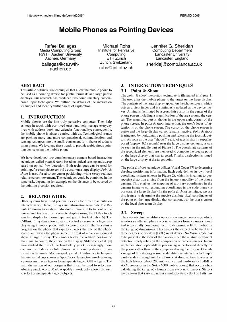
Mobile Phones as Pointing Devices
Rafael BallagasMedia Computing GroupRWTH Aachen University
Aachen, [email protected]
aachen.de
Michael RohsInstitute for Pervasive
ComputingETH Zurich
Zurich, [email protected]
Jennifer G. SheridanComputing DepartmentLancaster UniversityLancaster, England
ABSTRACTThis article outlines two techniques that allow the mobile phone tobe used as a pointing device for public terminals and large publicdisplays. Our research has produced two complimentary camera-based input techniques. We outline the details of the interactiontechniques and identify further areas of exploration.
1. INTRODUCTIONMobile phones are the first truly pervasive computer. They helpus keep in touch with our loved ones, and help manage everydaylives with address book and calendar functionality; consequently,the mobile phone is always carried with us. Technological trendsare packing more and more computational, communication, andsensing resources into the small, convenient form factor of today’ssmart phone. We leverage these trends to provide a ubiquitous poin-ting device using the mobile phone.
We have developed two complementary camera-based interactiontechniques called point & shoot based on optical sensing and sweepbased on optical-flow detection. Both techniques can be used forpointing, for example, to control a cursor on a large display. Point &shoot is used for absolute cursor positioning, while sweep realizesrelative cursor movement. The techniques could be combined in thesame task, depending for example on the distance to be covered orthe pointing precision required.
2. RELATEDWORKOther systems have used personal devices for direct manipulationinteractions with large displays and information terminals. The Re-mote Commander enables individuals to use a PDA to control themouse and keyboard on a remote display using the PDA’s touchsensitive display for mouse input and graffiti for text entry [6]. TheC-Blink [5] system allows users to control a cursor on a large dis-play using a mobile phone with a colored screen. The user runs aprogram on the phone that rapidly changes the hue of the phonescreen and waves the phone screen in front of a camera mountedabove a large display. The camera tracks the relative position ofthis signal to control the cursor on the display. Slifverberg et al. [8]have studied the use of the handheld joystick, increasingly morecommon on today’s mobile phones, as a pointing device for in-formation terminals. Madhavapeddy et al. [4] introduce techniquesthat use visual tags known as SpotCodes. Interaction involves usinga phonecam to scan tags or to manipulate tagged GUI widgets. Themain distinction of our design is that it can be used to select anyarbitrary pixel, where Madhavapeddy’s work only allows the userto select or manipulate tagged objects.
3. INTERACTION TECHNIQUES3.1 Point & ShootThe point & shoot interaction technique is illustrated in Figure 1.The user aims the mobile phone to the target on the large display.The contents of the large display appear on the phone screen, whichacts as a view finder and is continously updated as the device mo-ves. Aiming is facilitated by a cross-hair cursor in the center of thephone screen including a magnification of the area around the cen-ter. The magnified part is shown in the upper right corner of thephone screen. In point & shoot interaction, the user’s locus of at-tention is on the phone screen. The cursor on the phone screen isactive and the large display cursor remains inactive. Point & shootis triggered by horizontally pushing and releasing the joystick but-ton. As soon as the user “shoots,” a grid of tags is shortly superim-posed (approx. 0.5 seconds) over the large display contents, as canbe seen in the middle part of Figure 1. The coordinate systems ofthe recognized elements are then used to compute the precise pointon the large display that was targeted. Finally, a selection is issuedon the large display at the target point.
The point & shoot technique utilizes Visual Codes [7] to determineabsolute positioning information. Each code defines its own localcoordinate system (shown in Figure 2), which is invariant to per-spective distortion arising from the inherent mobility of the phonecamera. This enables the mapping of arbitrary coordinates in thecamera image to corresponding coordinates in the code plane (inour case, the large display). In the point & shoot technique, we usethis feature to determine the precise absolute pixel coordinates ofthe point on the large display that corresponds to the user’s cursoron the local phonecam display.
3.2 SweepThe sweep technique utilizes optical-flow image processing, whichinvolves rapidly sampling successive images from a camera phoneand sequentially comparing them to determine relative motion inthe (x, y, α) dimensions. This enables the camera to be used as athree degrees of freedom (DOF) input device. No Visual Code hasto be present in the view of the camera, since the relative movementdetection solely relies on the comparison of camera images. In ourimplementation, optical-flow processing is performed directly onthe phone rather than on the computer driving the display. One ad-vantage of this strategy is user scalability; the interaction techniqueeasily scales to a high number of users. A disadvantage however, isthe high latency (about 200 ms) with current hardware (a 104MHzARM processor in the Nokia 6600 mobile phone) that occurs whencalculating the (x, y, α) changes from successive images. Studieshave shown that system lag has a multiplicative effect on Fitts’ in-
http://www.medien.ifi.lmu.de/permid2005/ PERMID 2005
27
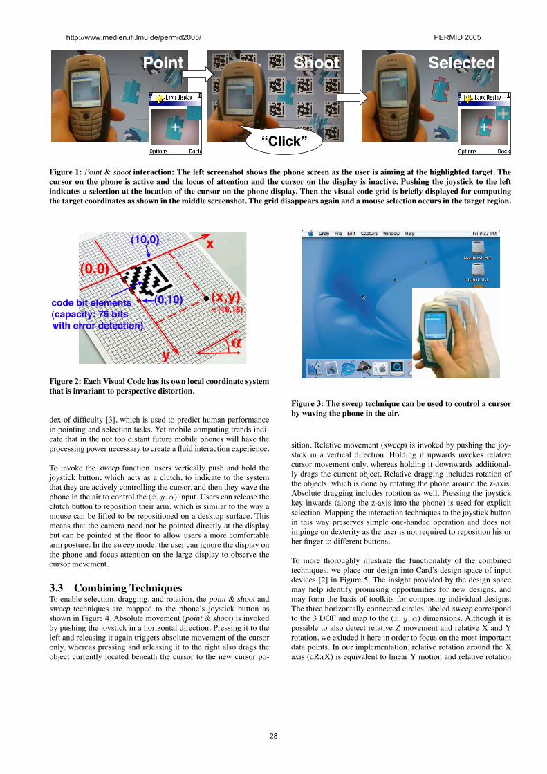
ShootPoint
“Click”
Selected
Figure 1: Point & shoot interaction: The left screenshot shows the phone screen as the user is aiming at the highlighted target. Thecursor on the phone is active and the locus of attention and the cursor on the display is inactive. Pushing the joystick to the leftindicates a selection at the location of the cursor on the phone display. Then the visual code grid is briefly displayed for computingthe target coordinates as shown in the middle screenshot. The grid disappears again and a mouse selection occurs in the target region.
x
y
(0,0)
(x,y)= (16,18)
(10,0)
(0,10)code bit elements(capacity: 76 bits with error detection)
Figure 2: Each Visual Code has its own local coordinate systemthat is invariant to perspective distortion.
dex of difficulty [3], which is used to predict human performancein pointing and selection tasks. Yet mobile computing trends indi-cate that in the not too distant future mobile phones will have theprocessing power necessary to create a fluid interaction experience.
To invoke the sweep function, users vertically push and hold thejoystick button, which acts as a clutch, to indicate to the systemthat they are actively controlling the cursor, and then they wave thephone in the air to control the (x, y, α) input. Users can release theclutch button to reposition their arm, which is similar to the way amouse can be lifted to be repositioned on a desktop surface. Thismeans that the camera need not be pointed directly at the displaybut can be pointed at the floor to allow users a more comfortablearm posture. In the sweep mode, the user can ignore the display onthe phone and focus attention on the large display to observe thecursor movement.
3.3 Combining TechniquesTo enable selection, dragging, and rotation, the point & shoot andsweep techniques are mapped to the phone’s joystick button asshown in Figure 4. Absolute movement (point & shoot) is invokedby pushing the joystick in a horizontal direction. Pressing it to theleft and releasing it again triggers absolute movement of the cursoronly, whereas pressing and releasing it to the right also drags theobject currently located beneath the cursor to the new cursor po-
Figure 3: The sweep technique can be used to control a cursorby waving the phone in the air.
sition. Relative movement (sweep) is invoked by pushing the joy-stick in a vertical direction. Holding it upwards invokes relativecursor movement only, whereas holding it downwards additional-ly drags the current object. Relative dragging includes rotation ofthe objects, which is done by rotating the phone around the z-axis.Absolute dragging includes rotation as well. Pressing the joystickkey inwards (along the z-axis into the phone) is used for explicitselection. Mapping the interaction techniques to the joystick buttonin this way preserves simple one-handed operation and does notimpinge on dexterity as the user is not required to reposition his orher finger to different buttons.
To more thoroughly illustrate the functionality of the combinedtechniques, we place our design into Card’s design space of inputdevices [2] in Figure 5. The insight provided by the design spacemay help identify promising opportunities for new designs, andmay form the basis of toolkits for composing individual designs.The three horizontally connected circles labeled sweep correspondto the 3 DOF and map to the (x, y, α) dimensions. Although it ispossible to also detect relative Z movement and relative X and Yrotation, we exluded it here in order to focus on the most importantdata points. In our implementation, relative rotation around the Xaxis (dR:rX) is equivalent to linear Y motion and relative rotation
http://www.medien.ifi.lmu.de/permid2005/ PERMID 2005
28
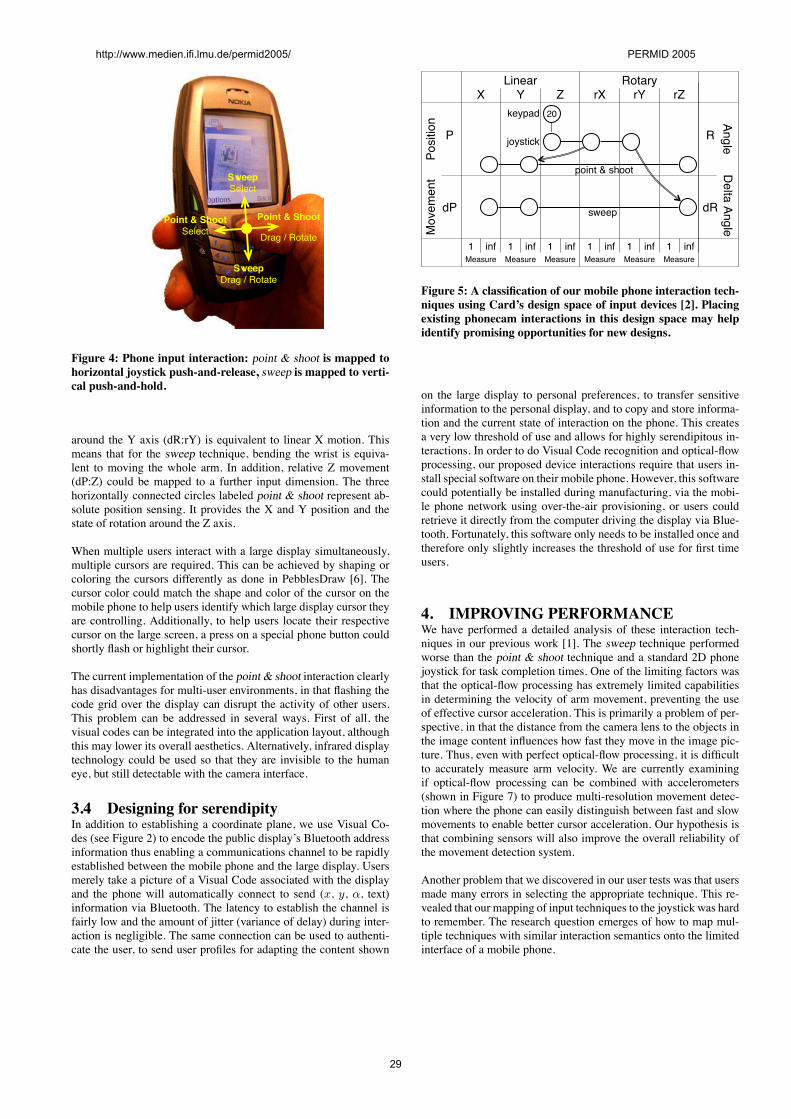
toohS & tnioPtceleS
toohS & tnioP
etatoR / garD
peewStceleS
peewSetatoR / garD
Figure 4: Phone input interaction: point & shoot is mapped tohorizontal joystick push-and-release, sweep is mapped to verti-cal push-and-hold.
around the Y axis (dR:rY) is equivalent to linear X motion. Thismeans that for the sweep technique, bending the wrist is equiva-lent to moving the whole arm. In addition, relative Z movement(dP:Z) could be mapped to a further input dimension. The threehorizontally connected circles labeled point & shoot represent ab-solute position sensing. It provides the X and Y position and thestate of rotation around the Z axis.
When multiple users interact with a large display simultaneously,multiple cursors are required. This can be achieved by shaping orcoloring the cursors differently as done in PebblesDraw [6]. Thecursor color could match the shape and color of the cursor on themobile phone to help users identify which large display cursor theyare controlling. Additionally, to help users locate their respectivecursor on the large screen, a press on a special phone button couldshortly flash or highlight their cursor.
The current implementation of the point & shoot interaction clearlyhas disadvantages for multi-user environments, in that flashing thecode grid over the display can disrupt the activity of other users.This problem can be addressed in several ways. First of all, thevisual codes can be integrated into the application layout, althoughthis may lower its overall aesthetics. Alternatively, infrared displaytechnology could be used so that they are invisible to the humaneye, but still detectable with the camera interface.
3.4 Designing for serendipityIn addition to establishing a coordinate plane, we use Visual Co-des (see Figure 2) to encode the public display’s Bluetooth addressinformation thus enabling a communications channel to be rapidlyestablished between the mobile phone and the large display. Usersmerely take a picture of a Visual Code associated with the displayand the phone will automatically connect to send (x, y, α, text)information via Bluetooth. The latency to establish the channel isfairly low and the amount of jitter (variance of delay) during inter-action is negligible. The same connection can be used to authenti-cate the user, to send user profiles for adapting the content shown
raeniL
rusaeM ei1 nf
rusaeM ei1 nf
rusaeM ei1 nf
rusaeM ei1 nf
rusaeM ei1 nf
rusaeM ei1 nf
YX Z rX rY rZyratoR
Mov
emen
tPo
sitio
n
P
Pd
R
Rd
Delta AngleAngle
02dapyek
kcitsyoj
toohs & tniop
peews
Figure 5: A classification of our mobile phone interaction tech-niques using Card’s design space of input devices [2]. Placingexisting phonecam interactions in this design space may helpidentify promising opportunities for new designs.
on the large display to personal preferences, to transfer sensitiveinformation to the personal display, and to copy and store informa-tion and the current state of interaction on the phone. This createsa very low threshold of use and allows for highly serendipitous in-teractions. In order to do Visual Code recognition and optical-flowprocessing, our proposed device interactions require that users in-stall special software on their mobile phone. However, this softwarecould potentially be installed during manufacturing, via the mobi-le phone network using over-the-air provisioning, or users couldretrieve it directly from the computer driving the display via Blue-tooth. Fortunately, this software only needs to be installed once andtherefore only slightly increases the threshold of use for first timeusers.
4. IMPROVING PERFORMANCEWe have performed a detailed analysis of these interaction tech-niques in our previous work [1]. The sweep technique performedworse than the point & shoot technique and a standard 2D phonejoystick for task completion times. One of the limiting factors wasthat the optical-flow processing has extremely limited capabilitiesin determining the velocity of arm movement, preventing the useof effective cursor acceleration. This is primarily a problem of per-spective, in that the distance from the camera lens to the objects inthe image content influences how fast they move in the image pic-ture. Thus, even with perfect optical-flow processing, it is difficultto accurately measure arm velocity. We are currently examiningif optical-flow processing can be combined with accelerometers(shown in Figure 7) to produce multi-resolution movement detec-tion where the phone can easily distinguish between fast and slowmovements to enable better cursor acceleration. Our hypothesis isthat combining sensors will also improve the overall reliability ofthe movement detection system.
Another problem that we discovered in our user tests was that usersmade many errors in selecting the appropriate technique. This re-vealed that our mapping of input techniques to the joystick was hardto remember. The research question emerges of how to map mul-tiple techniques with similar interaction semantics onto the limitedinterface of a mobile phone.
http://www.medien.ifi.lmu.de/permid2005/ PERMID 2005
29
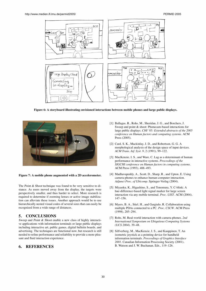
Figure 6: A storyboard illustrating envisioned interactions between mobile phones and large public displays.
Figure 7: A mobile phone augmented with a 2D accelerometer.
The Point & Shoot technique was found to be very sensitive to di-stance. As users moved away from the display, the targets wereperspectively smaller, and thus harder to select. More research isrequired to determine if zooming lenses or active image stabiliza-tion can alleviate these issues. Another approach would be to usehierarchically nested visual codes of several sizes that can easily berecognized from a wide range of distances.
5. CONCLUSIONSSweep and Point & Shoot enable a new class of highly interacti-ve applications with information terminals or large public displaysincluding interactive art, public games, digital bulletin boards, andadvertising. The techniques are functional now, but research is stillneeded to refine performance and reliability to provide a more plea-sant and fluid interaction experience.
6. REFERENCES
[1] Ballagas, R., Rohs, M., Sheridan, J. G., and Borchers, J.Sweep and point & shoot: Phonecam-based interactions forlarge public displays. CHI ’05: Extended abstracts of the 2005conference on Human factors and computing systems. ACMPress (2005).
[2] Card, S. K., Mackinlay, J. D., and Robertson, G. G. Amorphological analysis of the design space of input devices.ACM Trans. Inf. Syst. 9, 2 (1991), 99–122.
[3] MacKenzie, I. S., and Ware, C. Lag as a determinant of humanperformance in interactive systems. Proceedings of theSIGCHI conference on Human factors in computing systems.ACM Press (1993), 488–493.
[4] Madhavapeddy, A., Scott, D., Sharp, R., and Upton, E. Usingcamera-phones to enhance human-computer interaction.Adjunct Proc. of Ubicomp. Springer-Verlag (2004).
[5] Miyaoku, K., Higashino, S., and Tonomura, Y. C-blink: Ahue-difference-based light signal marker for large screeninteraction via any mobile terminal. Proc. UIST. ACM (2004),147–156.
[6] Myers, B. A., Stiel, H., and Gargiulo, R. Collaboration usingmultiple PDAs connected to a PC. Proc. CSCW. ACM Press(1998), 285–294.
[7] Rohs, M. Real-world interaction with camera-phones. 2ndInternational Symposium on Ubiquitous Computing Systems(UCS 2004). 39–48.
[8] Silfverberg, M., MacKenzie, I. S., and Kauppinen, T. Anisometric joystick as a pointing device for handheldinformation terminals. Proceedings of Graphics Interface2001. Canadian Information Processing Society (2001),B. Watson and J. W. Buchanan, Eds., 119–126.
http://www.medien.ifi.lmu.de/permid2005/ PERMID 2005
30
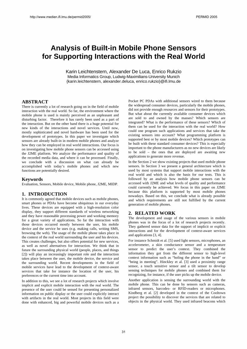
Analysis of Built-in Mobile Phone Sensors for Supporting Interactions with the Real World
Karin Leichtenstern, Alexander De Luca, Enrico Rukzio Media Informatics Group, Ludwig-Maximilians-University Munich {karin.leichtenstern, alexander.deluca, enrico.rukzio}@ifi.lmu.de
ABSTRACT There is currently a lot of research going on in the field of mobile interaction with the real world. So far, the environment where the mobile phone is used is mainly perceived as an unpleasant and disturbing factor. Therefore it has rarely been used as a part of the interaction. But on the other hand there is a huge potential for new kinds of the interactions and novel services. Until now, mostly sophisticated and novel hardware has been used for the development of prototypes. In this paper we investigate which sensors are already built-in in modern mobile phones and analyze how they can be employed in real world interactions. Our focus is on investigating how mobile phone sensors can be accessed using the J2ME platform. We analyze the performance and quality of the recorded media data, and where it can be processed. Finally, we conclude with a discussion on what can already be accomplished with today’s mobile phones and which new functions are potentially desired.
Keywords Evaluation, Sensors, Mobile device, Mobile phone, J2ME, MIDP.
1. INTRODUCTION It is commonly agreed that mobile devices such as mobile phones, smart phones or PDAs have become ubiquitous in our everyday lives. These devices are equipped with a high-resolution color display, they support different standards of wireless networking and they have reasonable processing power and working memory for a great variety of applications. So far the interaction with those devices occurred mostly between the user, his mobile device and the service he uses (e.g. making calls, writing SMS, browsing the web). The usage of the mobile phone takes place in the context of the real world surrounding the user and his devices. This creates challenges, but also offers potential for new services, as well as novel alternatives for interaction. We think that in future the surrounding physical world (people, places, and things [2]) will play an increasingly important role and the interaction takes place between the user, the mobile device, the service and the surrounding world. Recent developments in the field of mobile services have lead to the development of context-aware services that take for instance the location of the user, his preferences or the current time into account. In addition to this, we see a lot of research projects which involve implicit and explicit mobile interaction with the real world. The presence of the user could be sensed for presenting personalized information on public display or the user could explicitly interact with artifacts in the real world. Most projects in this field were done with enhanced, big and powerful mobile devices such as a
Pocket PC PDAs with additional sensors wired to them because the widespread consumer devices, particularly the mobile phones, did not provide enough resources and sensors for their prototypes. But what about the currently available consumer devices which are sold to and owned by the masses? Which sensors are integrated? What is the performance of these sensors? Which of them can be used for the interaction with the real world? How could one program such applications and services that take the existing sensors into account? What programming platform is supported best or by most mobile devices? Which prototypes can be built with these standard consumer devices? This is especially important to the phone manufacturers as no new devices are likely to be sold – the ones that are deployed are awaiting new applications to generate more revenue. In the Section 2 we show existing projects that used mobile phone sensors. In Section 3 we present a general architecture which is used by most systems that support mobile interactions with the real world and which is also the basis for our tests. This is followed by an analysis how mobile phone sensors can be accessed with J2ME and what levels of quality and performance could currently be achieved. We focus in this paper on J2ME because this platform is supported by most mobile phones nowadays. Based on this, we conclude what is already possible and which requirements are still not fulfilled by the current generation of mobile phones.
2. RELATED WORK The development and usage of the various sensors in mobile phones was in the focus of a lot of research projects recently. They gathered sensor data for the support of implicit or explicit interactions and for the development of context-aware services and applications [3, 4]. For instance Schmidt et al. [5] used light sensors, microphones, an accelerometer, a skin conductance sensor and a temperature sensor to predict the user’s context. They combined the information they got from the different sensor to high-level context information such as “holing the phone in the hand” or “being in meeting”. Hinckley et al. [3] used a proximity range sensor, a touch sensitive sensor and a tilt sensor to develop sensing techniques for mobile phones and combined them for recognizing, for instance, if the user picks up the mobile device. Another application is sensing the surrounding world with the mobile phone. This can be done by sensors such as cameras, infrared sensors, barcodes- or RFID-readers or microphones. Kindberg et al. [2] developed in the context of the Cooltown project the possibility to discover the services that are related to objects in the physical world. They used infrared beacons which
http://www.medien.ifi.lmu.de/permid2005/ PERMID 2005
31
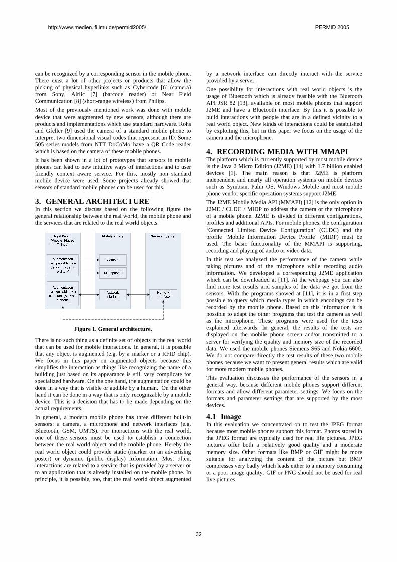
can be recognized by a corresponding sensor in the mobile phone. There exist a lot of other projects or products that allow the picking of physical hyperlinks such as Cybercode [6] (camera) from Sony, Airlic [7] (barcode reader) or Near Field Communication [8] (short-range wireless) from Philips. Most of the previously mentioned work was done with mobile device that were augmented by new sensors, although there are products and implementations which use standard hardware. Rohs and Gfeller [9] used the camera of a standard mobile phone to interpret two dimensional visual codes that represent an ID. Some 505 series models from NTT DoCoMo have a QR Code reader which is based on the camera of these mobile phones. It has been shown in a lot of prototypes that sensors in mobile phones can lead to new intuitive ways of interactions and to user friendly context aware service. For this, mostly non standard mobile device were used. Some projects already showed that sensors of standard mobile phones can be used for this.
3. GENERAL ARCHITECTURE In this section we discuss based on the following figure the general relationship between the real world, the mobile phone and the services that are related to the real world objects.
Figure 1. General architecture.
There is no such thing as a definite set of objects in the real world that can be used for mobile interactions. In general, it is possible that any object is augmented (e.g. by a marker or a RFID chip). We focus in this paper on augmented objects because this simplifies the interaction as things like recognizing the name of a building just based on its appearance is still very complicate for specialized hardware. On the one hand, the augmentation could be done in a way that is visible or audible by a human. On the other hand it can be done in a way that is only recognizable by a mobile device. This is a decision that has to be made depending on the actual requirements. In general, a modern mobile phone has three different built-in sensors: a camera, a microphone and network interfaces (e.g. Bluetooth, GSM, UMTS). For interactions with the real world, one of these sensors must be used to establish a connection between the real world object and the mobile phone. Hereby the real world object could provide static (marker on an advertising poster) or dynamic (public display) information. Most often, interactions are related to a service that is provided by a server or to an application that is already installed on the mobile phone. In principle, it is possible, too, that the real world object augmented
by a network interface can directly interact with the service provided by a server. One possibility for interactions with real world objects is the usage of Bluetooth which is already feasible with the Bluetooth API JSR 82 [13], available on most mobile phones that support J2ME and have a Bluetooth interface. By this it is possible to build interactions with people that are in a defined vicinity to a real world object. New kinds of interactions could be established by exploiting this, but in this paper we focus on the usage of the camera and the microphone.
4. RECORDING MEDIA WITH MMAPI The platform which is currently supported by most mobile device is the Java 2 Micro Edition (J2ME) [14] with 1.7 billion enabled devices [1]. The main reason is that J2ME is platform independent and nearly all operation systems on mobile devices such as Symbian, Palm OS, Windows Mobile and most mobile phone vendor specific operation systems support J2ME. The J2ME Mobile Media API (MMAPI) [12] is the only option in J2ME / CLDC / MIDP to address the camera or the microphone of a mobile phone. J2ME is divided in different configurations, profiles and additional APIs. For mobile phones, the configuration ‘Connected Limited Device Configuration’ (CLDC) and the profile ‘Mobile Information Device Profile’ (MIDP) must be used. The basic functionality of the MMAPI is supporting, recording and playing of audio or video data. In this test we analyzed the performance of the camera while taking pictures and of the microphone while recording audio information. We developed a corresponding J2ME application which can be downloaded at [11]. At the webpage you can also find more test results and samples of the data we got from the sensors. With the programs showed at [11], it is in a first step possible to query which media types in which encodings can be recorded by the mobile phone. Based on this information it is possible to adapt the other programs that test the camera as well as the microphone. These programs were used for the tests explained afterwards. In general, the results of the tests are displayed on the mobile phone screen and/or transmitted to a server for verifying the quality and memory size of the recorded data. We used the mobile phones Siemens S65 and Nokia 6600. We do not compare directly the test results of these two mobile phones because we want to present general results which are valid for more modern mobile phones. This evaluation discusses the performance of the sensors in a general way, because different mobile phones support different formats and allow different parameter settings. We focus on the formats and parameter settings that are supported by the most devices.
4.1 Image In this evaluation we concentrated on to test the JPEG format because most mobile phones support this format. Photos stored in the JPEG format are typically used for real life pictures. JPEG pictures offer both a relatively good quality and a moderate memory size. Other formats like BMP or GIF might be more suitable for analyzing the content of the picture but BMP compresses very badly which leads either to a memory consuming or a poor image quality. GIF or PNG should not be used for real live pictures.
http://www.medien.ifi.lmu.de/permid2005/ PERMID 2005
32
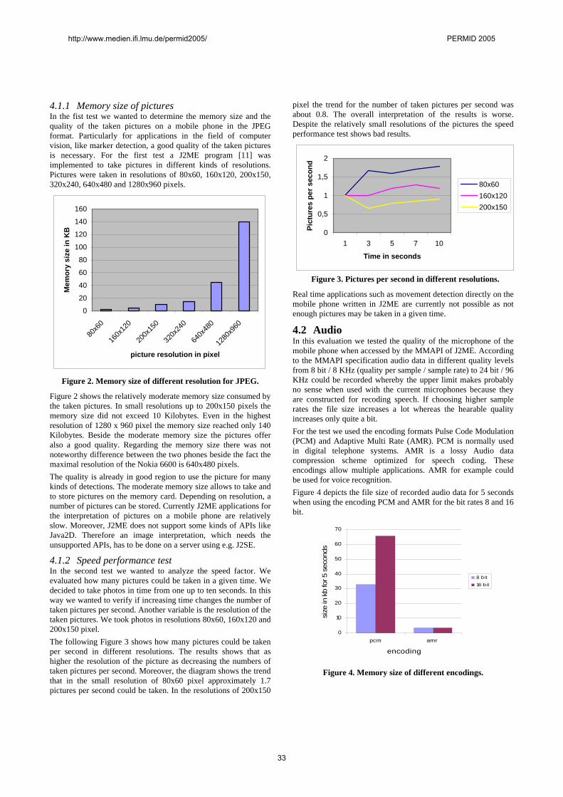
4.1.1 Memory size of pictures In the fist test we wanted to determine the memory size and the quality of the taken pictures on a mobile phone in the JPEG format. Particularly for applications in the field of computer vision, like marker detection, a good quality of the taken pictures is necessary. For the first test a J2ME program [11] was implemented to take pictures in different kinds of resolutions. Pictures were taken in resolutions of 80x60, 160x120, 200x150, 320x240, 640x480 and 1280x960 pixels.
0
20
40
60
80
100
120
140
160
80x6
0
160x
120
200x
150
320x
240
640x
480
1280
x960
picture resolution in pixel
Mem
ory
size
in K
B
Figure 2. Memory size of different resolution for JPEG.
Figure 2 shows the relatively moderate memory size consumed by the taken pictures. In small resolutions up to 200x150 pixels the memory size did not exceed 10 Kilobytes. Even in the highest resolution of 1280 x 960 pixel the memory size reached only 140 Kilobytes. Beside the moderate memory size the pictures offer also a good quality. Regarding the memory size there was not noteworthy difference between the two phones beside the fact the maximal resolution of the Nokia 6600 is 640x480 pixels. The quality is already in good region to use the picture for many kinds of detections. The moderate memory size allows to take and to store pictures on the memory card. Depending on resolution, a number of pictures can be stored. Currently J2ME applications for the interpretation of pictures on a mobile phone are relatively slow. Moreover, J2ME does not support some kinds of APIs like Java2D. Therefore an image interpretation, which needs the unsupported APIs, has to be done on a server using e.g. J2SE.
4.1.2 Speed performance test In the second test we wanted to analyze the speed factor. We evaluated how many pictures could be taken in a given time. We decided to take photos in time from one up to ten seconds. In this way we wanted to verify if increasing time changes the number of taken pictures per second. Another variable is the resolution of the taken pictures. We took photos in resolutions 80x60, 160x120 and 200x150 pixel. The following Figure 3 shows how many pictures could be taken per second in different resolutions. The results shows that as higher the resolution of the picture as decreasing the numbers of taken pictures per second. Moreover, the diagram shows the trend that in the small resolution of 80x60 pixel approximately 1.7 pictures per second could be taken. In the resolutions of 200x150
pixel the trend for the number of taken pictures per second was about 0.8. The overall interpretation of the results is worse. Despite the relatively small resolutions of the pictures the speed performance test shows bad results.
0
0,5
1
1,5
2
1 3 5 7 10
Time in seconds
Pict
ures
per
sec
ond
80x60160x120200x150
Figure 3. Pictures per second in different resolutions.
Real time applications such as movement detection directly on the mobile phone written in J2ME are currently not possible as not enough pictures may be taken in a given time.
4.2 Audio In this evaluation we tested the quality of the microphone of the mobile phone when accessed by the MMAPI of J2ME. According to the MMAPI specification audio data in different quality levels from 8 bit / 8 KHz (quality per sample / sample rate) to 24 bit / 96 KHz could be recorded whereby the upper limit makes probably no sense when used with the current microphones because they are constructed for recoding speech. If choosing higher sample rates the file size increases a lot whereas the hearable quality increases only quite a bit. For the test we used the encoding formats Pulse Code Modulation (PCM) and Adaptive Multi Rate (AMR). PCM is normally used in digital telephone systems. AMR is a lossy Audio data compression scheme optimized for speech coding. These encodings allow multiple applications. AMR for example could be used for voice recognition. Figure 4 depicts the file size of recorded audio data for 5 seconds when using the encoding PCM and AMR for the bit rates 8 and 16 bit.
0
10
20
30
40
50
60
70
pcm amr
encoding
size
in k
b fo
r 5 s
econ
ds
8 bit16 bit
Figure 4. Memory size of different encodings.
http://www.medien.ifi.lmu.de/permid2005/ PERMID 2005
33
The result of this test can be compared to the camera test. The file sizes are in a region that allows in general their processing by the mobile phone. Unfortunately, there is, too, no API available for the interpretation and modification of audio date which postpones this task probably to the server. The file sizes for the encoding AMR show a typical effect that we recognized particularly during the evolution of the microphone. In principal there are a lot of possible parameters when recording audio data such as encoding, sample rate or bits per sample. Often there exist restrictions regarding these parameters that are not known by the programmer. In the Figure 4 for instance, the mobile phone did support only 8 bit per sample and not 16 bit per sample. This can be only recognized when looking on the file size or by analyzing the generated audio file afterwards.
5. CONCLUSION In our analysis we found out that in most of the cases the quality of the sensor data is sufficiently good. With respect to the performance, the knowledge about the recorded quality, the processing of the data and the development of platform independent applications for interactions with the real world, there are still considerable problems. The performance when accessing the camera is currently not sufficient for supporting gestures where about 10 to 15 frames per second are needed because we showed in our test that currently at maximum 2 pictures per second could be recorded. Another problem is the lack of the knowledge on the quality of the recorded data. When building applications that should run on a lot of mobile devices it is very complicate to test every mobile phone before delivering the mobile phone application or to integrate a test routine that runs after the installation of the program on the mobile phone. It is currently already possible to ask the mobile phone for the supported audio or video encodings. But it would be a great advantage for this kind of programs to know which parameters (e.g. resolution, bit per sample, sample rate) are supported for a specific encoding on a mobile phone. Unless such simple or even more sophisticated methods regarding the quality of service are not present, it is very complicated to develop general programs that use sensor data and which run on several mobile phones. The next step after recording of the media is the analysis of the audio or video data. Currently there are no APIs available for this task on the mobile phones because J2ME only includes the basic APIs that are needed for the most common applications. Hence the developer can integrate some classes for the interpretation of the sensor data in the program on the mobile device or transmit the data to the server and analyze there the sensor data. The first option has the advantage that no data must be transmitted. But for the processing of the media data on the mobile phone there is often not enough memory or processing power available. The advantage of the transmission of the media data to a server is that a server has a potentially huge set of memory and enough processing power. The disadvantages of this approach are the costs for data transmission and a delay which is not helpful for the most kind of interactions. Our conclusion is that the development of prototypes for mobile interactions with the real world is already possible when using modern mobile devices whose capabilities are tested intensively before. But we have to wait a few years for matured
implementations of the corresponding APIs on the mobile phones, as well as for more processing power and working memory on the mobile phones to support real world interactions.
6. ACKNOWLEDGMENT The authors wish to express their gratitude to the other participants of the course “programming of applications for mobile devices”, to Nokia and Siemens for lending us mobile phones and to Albrecht Schmidt for their kind support. This work was performed in the context of the framework of IST Project Simplicity funded by the EU [15] and the DFG funded research group “Embedded Interaction” [10].
7. REFERENCES [1] Report on Heise.de from the 25/10/2004 – News page of a German IT publishing house, http://www.heise.de/newsticker/meldung/52477 [2] Kindberg, T.; Barton, J.; Morgan, J.; Becker, G.; Caswell, D.; Debaty, P.; Gopal, G.; Frid, M.; Krishnan, V.; Morris, H.; Schettino, J.; Serra, B.; Spasojevic, M. 2002. People, Places, Things: Web Presence for the Real World. In: Mobile Networks and Applications, 7(5):365–376, 2002. [3] Hinckley, K.; Pierce, J.; Sinclair, M.; Horvitz, E. 2000. Sensing techniques for mobile interaction. In: UIST '00: Proceedings of the 13th annual ACM symposium on User interface software and technology, pp. 91—100, San Diego, California, United States, 2000. [4] Gellersen, H.; Schmidt, A.; Beigl, M. 2002. Multi-sensor context-awareness in mobile devices and smart artifacts. In: Journal Mobile Networks and Applications 7, pp. 341–351, Kluwer Academic Publishersm, 2002. [5] Schmidt, A.; Aidoo, K.; Takaluoma, A.; Tuomela, U.; Van Laerhoven, K.; Van de Velde, W. 1999. Advanced Interaction in Context. In: HUC '99: Proceedings of the 1st international symposium on Handheld and Ubiquitous Computing, pp. 89-101, Karlsruhe, Germany, 1999. [6] Rekimoto, J.; Ayatsuka, Y. 2000. CyberCode: Designing Augmented Reality Environments with Visual Tags. In: Proceedings of DARE, 2000. [7] Airlic www.airclic.com [8] Near Field Communication from Philips Semiconductors http://www.semiconductors.philips.com/markets/identification/ products/nfc/ [9] Rohs, M.; Gfeller, B. 2004. Using Camera-Equipped Mobile Phones for Interacting with Real-World Objects. In: Alois Ferscha, Horst Hoertner, Gabriele Kotsis (Eds.): Advances in Pervasive Computing, Austrian Computer Society (OCG), ISBN 3-85403-176-9, pp. 265-271, Vienna, Austria, April 2004. [10] Research Group "Embedded Interaction”, http://www.hcilab.org/ [11] J2ME Application for testing the sensors http://www.hcilab.org/resources/tutorials.htm [12] Mobile Media API, http://jcp.org/en/jsr/detail?id=135 [13] JSR 82, http://www.jcp.org/en/jsr/detail?id=82 [14] J2ME, http://java.sun.com/j2me/ [15] Simplicity Project, http://www.ist-simplicity.org
http://www.medien.ifi.lmu.de/permid2005/ PERMID 2005
34
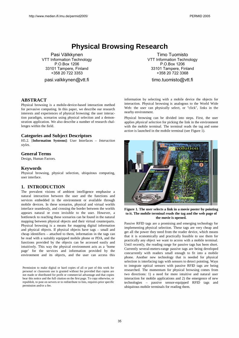
Physical Browsing ResearchPasi Välkkynen
VTT Information TechnologyP.O.Box 1206
33101 Tampere, Finland+358 20 722 3353
Timo TuomistoVTT Information Technology
P.O.Box 120633101 Tampere, Finland
+358 20 722 3368
ABSTRACTPhysical browsing is a mobiledevicebased interaction methodfor pervasive computing. In this paper, we describe our researchinterests and experiences of physical browsing: the user interaction paradigm, scenarios using physical selection and a demonstration application. We also describe a number of research challenges within the field.
Categories and Subject DescriptorsH5.2. [Information Systems]: User Interfaces – Interactionstyles.
General TermsDesign, Human Factors.
KeywordsPhysical browsing, physical selection, ubiquitous computing,user interface.
1. INTRODUCTIONThe prevalent visions of ambient intelligence emphasise anatural interaction between the user and the functions andservices embedded in the environment or available throughmobile devices. In these scenarios, physical and virtual worldsinterlace seamlessly, and crossing the border between the worldsappears natural or even invisible to the user. However, abottleneck to reaching these scenarios can be found in the naturalmapping between physical objects and their virtual counterparts.Physical browsing is a means for mapping digital informationand physical objects. If physical objects have tags – small andcheap identifiers – attached to them, information in the tags canbe read with a suitably equipped mobile phone or PDA, and thefunctions provided by the objects can be accessed easily andintuitively. This way the physical environment acts as a ‘homepage’ for the services and information provided by theenvironment and its objects, and the user can access this
information by selecting with a mobile device the objects forinteraction. Physical browsing is analogous to the World WideWeb: the user can physically select, or "click", links in thenearby environment.Physical browsing can be divided into steps. First, the userapplies physical selection for picking the link in the environmentwith the mobile terminal. The terminal reads the tag and someaction is launched in the mobile terminal (see Figure 1).
Figure 1. The user selects a link in a movie poster by pointingto it. The mobile terminal reads the tag and the web page of
the movie is opened.Passive RFID tags are a promising and emerging technology forimplementing physical selection. These tags are very cheap andget all the power they need from the reader device, which meansthat it is economically and practically feasible to use them forpractically any object we want to access with a mobile terminal.Until recently, the reading range for passive tags has been short.Currently severalmetersrange passive tags are being developedconcurrently with readers small enough to fit into a mobilephone. Another new technology that is needed for physicalselection is interfacing tags with sensors to detect pointing. Waysto integrate optical sensors with passive RFID tags are beingresearched. The momentum for physical browsing comes fromtwo directions: 1) a need for more intuitive and natural userinteraction for mobile applications and 2) the emergence of newtechnologies – passive sensorequipped RFID tags andubiquitous mobile terminals for reading them.
Permission to make digital or hard copies of all or part of this work forpersonal or classroom use is granted without fee provided that copies arenot made or distributed for profit or commercial advantage and that copiesbear this notice and the full citation on the first page. To copy otherwise, orrepublish, to post on servers or to redistribute to lists, requires prior specificpermission and/or a fee.
http://www.medien.ifi.lmu.de/permid2005/ PERMID 2005
35
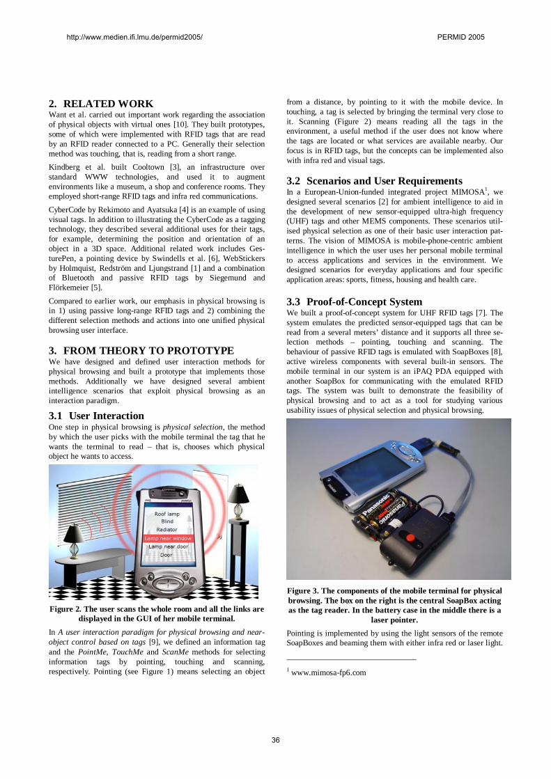
2. RELATED WORKWant et al. carried out important work regarding the associationof physical objects with virtual ones [10]. They built prototypes,some of which were implemented with RFID tags that are readby an RFID reader connected to a PC. Generally their selectionmethod was touching, that is, reading from a short range.Kindberg et al. built Cooltown [3], an infrastructure overstandard WWW technologies, and used it to augmentenvironments like a museum, a shop and conference rooms. Theyemployed shortrange RFID tags and infra red communications.
CyberCode by Rekimoto and Ayatsuka [4] is an example of usingvisual tags. In addition to illustrating the CyberCode as a taggingtechnology, they described several additional uses for their tags,for example, determining the position and orientation of anobject in a 3D space. Additional related work includes GesturePen, a pointing device by Swindells et al. [6], WebStickersby Holmquist, Redström and Ljungstrand [1] and a combinationof Bluetooth and passive RFID tags by Siegemund andFlörkemeier [5].
Compared to earlier work, our emphasis in physical browsing isin 1) using passive longrange RFID tags and 2) combining thedifferent selection methods and actions into one unified physicalbrowsing user interface.
3. FROM THEORY TO PROTOTYPEWe have designed and defined user interaction methods forphysical browsing and built a prototype that implements thosemethods. Additionally we have designed several ambientintelligence scenarios that exploit physical browsing as aninteraction paradigm.
3.1 User InteractionOne step in physical browsing is physical selection, the methodby which the user picks with the mobile terminal the tag that hewants the terminal to read – that is, chooses which physicalobject he wants to access.
Figure 2. The user scans the whole room and all the links aredisplayed in the GUI of her mobile terminal.
In A user interaction paradigm for physical browsing and nearobject control based on tags [9], we defined an information tagand the PointMe, TouchMe and ScanMe methods for selectinginformation tags by pointing, touching and scanning,respectively. Pointing (see Figure 1) means selecting an object
from a distance, by pointing to it with the mobile device. Intouching, a tag is selected by bringing the terminal very close toit. Scanning (Figure 2) means reading all the tags in theenvironment, a useful method if the user does not know wherethe tags are located or what services are available nearby. Ourfocus is in RFID tags, but the concepts can be implemented alsowith infra red and visual tags.
3.2 Scenarios and User RequirementsIn a EuropeanUnionfunded integrated project MIMOSA1, wedesigned several scenarios [2] for ambient intelligence to aid inthe development of new sensorequipped ultrahigh frequency(UHF) tags and other MEMS components. These scenarios utilised physical selection as one of their basic user interaction patterns. The vision of MIMOSA is mobilephonecentric ambientintelligence in which the user uses her personal mobile terminalto access applications and services in the environment. Wedesigned scenarios for everyday applications and four specificapplication areas: sports, fitness, housing and health care.
3.3 ProofofConcept SystemWe built a proofofconcept system for UHF RFID tags [7]. Thesystem emulates the predicted sensorequipped tags that can beread from a several meters’ distance and it supports all three selection methods – pointing, touching and scanning. Thebehaviour of passive RFID tags is emulated with SoapBoxes [8],active wireless components with several builtin sensors. Themobile terminal in our system is an iPAQ PDA equipped withanother SoapBox for communicating with the emulated RFIDtags. The system was built to demonstrate the feasibility ofphysical browsing and to act as a tool for studying varioususability issues of physical selection and physical browsing.
Figure 3. The components of the mobile terminal for physicalbrowsing. The box on the right is the central SoapBox actingas the tag reader. In the battery case in the middle there is a
laser pointer.Pointing is implemented by using the light sensors of the remoteSoapBoxes and beaming them with either infra red or laser light.
1 www.mimosafp6.com
http://www.medien.ifi.lmu.de/permid2005/ PERMID 2005
36
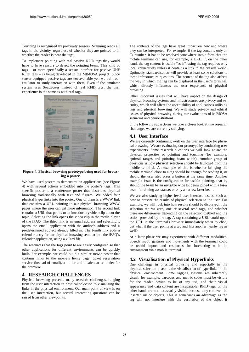
Touching is recognised by proximity sensors. Scanning reads alltags in the vicinity, regardless of whether they are pointed to orwhether the reader is near the tags.To implement pointing with real passive RFID tags they wouldhave to have sensors to detect the pointing beam. This kind oftags – or more specifically a sensor interface for passive UHFRFID tags – is being developed in the MIMOSA project. Sincesensorequipped passive tags are not available yet, we built ouremulator to study interaction with them. Even if the emulatorsystem uses SoapBoxes instead of real RFID tags, the userexperience is the same as with real tags.
Figure 4. Physical browsing prototype being used for browsing a poster.
We have used posters as demonstration applications (see Figure4) with several actions embedded into the poster’s tags. Thisspecific poster is a conference poster that describes physicalbrowsing traditionally with text and figures. We added fourphysical hyperlinks into the poster. One of them is a WWW linkthat contains a URL pointing to our physical browsing WWWpages where the user can get more information. The second linkcontains a URL that points to an introductory video clip about thetopic. Selecting the link opens the video clip in the media playerof the iPAQ. The third link is an email address and selecting itopens the email application with the author’s address and apredetermined subject already filled in. The fourth link adds acalendar entry for our physical browsing seminar into the iPAQ’scalendar application, using a vCard file.
The resources that the tags point to are easily configured so thatother applications for different environments can be quicklybuilt. For example, we could build a similar movie poster thatcontains links to the movie’s home page, ticket reservationservice (instead of email), a trailer and a calendar reminder forthe premiere.
4. RESEARCH CHALLENGESPhysical browsing presents many research challenges, rangingfrom the user interaction in physical selection to visualising thelinks in the physical environment. Our main point of view is onthe user interaction, but several interesting questions can beraised from other viewpoints.
The contents of the tags have great impact on how and wherethey can be interpreted. For example, if the tag contains only anID number, it has to be resolved somewhere into a form that themobile terminal can use, for example, a URL. If, on the otherhand, the tag content is usable "as is", using the tag requires onlylocal connectivity unless it contains a link to the outside world.Optimally, standardisation will provide at least some solutions tothese infrastructure questions. The content of the tag also affectsthe way in which the tag can be displayed in the user’s terminal,which directly influences the user experience of physicalbrowsing.Other important issues that will have impact on the design ofphysical browsing systems and infrastructures are privacy and security, which will affect the acceptability of applications utilisingtags and physical browsing. We will study privacy and ethicalissues of physical browsing during our evaluations of MIMOSAscenarios and demonstrations.
In the following subsections we take a closer look at two researchchallenges we are currently studying.
4.1 User InterfaceWe are currently continuing work on the user interface for physical browsing. We are evaluating our prototype by conducting userexperiments. Some research questions we will look at are thephysical properties of pointing and touching (for example,optimal ranges and pointing beam width). Another group ofquestions is how physical selection should be launched from themobile terminal. An example of this is whether bringing themobile terminal close to a tag should be enough for reading it, orshould the user also press a button at the same time. Anotherexample issue is the configuration for usable pointing, that is,should the beam be an invisible wide IR beam joined with a laserbeam for aiming assistance, or only a narrow laser beam.We are also studying higherlevel user interface issues, such ashow to present the results of physical selection to the user. Forexample, we will look into how results should be displayed if theselection returns zero, one or several read tags, and whetherthere are differences depending on the selection method and theaction provided by the tag. A tag containing a URL could openthe URL in the terminal's browser immediately when touched,but what if the user points at a tag and hits another nearby tag aswell?At a later phase we may experiment with different modalities.Speech input, gestures and movements with the terminal couldbe useful inputs and responses for interacting with theenvironment via a mobile terminal.
4.2 Visualisation of Physical HyperlinksOne challenge in physical browsing and especially in thephysical selection phase is the visualisation of hyperlinks in thephysical environment. Some tagging systems are inherentlyvisual; for example, barcodes and matrix codes must be visiblefor the reader device to be of any use, and their visualappearance and data content are inseparable. RFID tags, on theother hand, are not necessarily visible because they can even beinserted inside objects. This is sometimes an advantage as thetag will not interfere with the aesthetics of the object it
http://www.medien.ifi.lmu.de/permid2005/ PERMID 2005
37
augments, but from the user's point of view it can present aproblem.The main challenges in visualising physical hyperlinks are:
1. How can a user know if there is a link in a physical objector in an environment?
2. How can a user know in what part of the object the link is ifhe or she knows of its existence?
3. How can a user know what action or functionality willfollow from activating the link?
4. How can a user know how a link can be selected if the linkdoes not support all selection methods?
5. PRELIMINARY CONCLUSIONSIn this article we have discussed the concept of physicalbrowsing, a user interaction paradigm for associating physicalobjects and digital information related to them. As economic andpractical tagging systems are emerging, and being integratedwith ubiquitous mobile terminals – mobile phones and PDAs – itwill be possible to create ambient intelligence settings in greaterscale than ever before and truly connect the worlds that have sofar been separate, the physical world of our everydayenvironment and the digital world of the World Wide Web andother information systems.
6. REFERENCES[1] Holmquist, L. E., Redström, J. and Ljungstrand, P. Token
Based Access to Digital Information. Proceedings of FirstInternational Symposium on Handheld and Ubiquitous Computing (HUC) '99, Springer Verlag, 1999.
[2] Kaasinen, E., Rentto, K., Ikonen, V. and Välkkynen, P.2004. MIMOSA Initial Usage Scenarios. Available athttp://www.mimosafp6.com.
[3] Kindberg, T., Barton, J., Morgan, J., Becker, G., Caswell,D., Debaty, P., Gopal, G., Frid, M., Krishnan, V., Morris,H., Schettino, J., Serra, B. and Spasojevic, M. People,
Places, Things: Web Presence for the Real World. MobileNetworks and Applications, Volume 7, Issue 5 (October2002). 365376.
[4] Rekimoto, J. and Ayatsuka, Y. CyberCode: Designing Augmented Reality Environments with Visual Tags.Proceedings of DARE 2000 on Designing AugmentedReality Environments. Elsinore, Denmark. 110.
[5] Siegemund, F. and Flörkemeier, C. Interaction in PervasiveComputing Settings Using BluetoothEnabled Active Tagsand Passive RFID Technology Together with MobilePhones. Proceedings of the First IEEE International Conference on Pervasive Computing and Communications. 2003.
[6] Swindells, C., Inkpen, K. M., Dill, J. C. and Tory, Me. Thatone there! Pointing to establish device identity. 2002. Proceedings of the 15th annual ACM symposium on User interface software and technology. 151160.
[7] Tuomisto, T., Välkkynen, P. and Ylisaukkooja, A. RFIDTag Reader System Emulator to Support Touching, Pointingand Scanning. Accepted to Pervasive 2005 as a demonstration.
[8] Tuulari, E. and Ylisaukkooja, A. SoapBox: A Platform forUbiquitous Computing Research and Applications. LectureNotes in Computer Science 2414: Pervasive Computing. Zurich, CH, August 2628, 2002. Mattern, F. Naghshineh, M.(eds.). Springer (2002). 125 138.
[9] Välkkynen, P., Korhonen, I., Plomp, J., Tuomisto, T.,Cluitmans, L., Ailisto, H. and Seppä, H. A user interactionparadigm for physical browsing and nearobject controlbased on tags. Proceedings of Physical Interaction Workshopon Realworld User Interfaces, September 2003.
[10] Want, R., Fishkin, K. P., Gujar, A. and Harrison, B. L.Bridging Physical and Virtual Worlds with Electronic Tags.Proceedings of CHI 99, Pittsburgh, PA, USA. 370377.
http://www.medien.ifi.lmu.de/permid2005/ PERMID 2005
38
Task partitioning in smart environments Markus Ritala
Tampere University of Technology Institute of Electronics
P.O.Box 692, 33101 Tampere, Finland +358 50 482 1336
Jukka Vanhala Tampere University of Technology
Institute of Electronics P.O.Box 692, 33101 Tampere, Finland
+358 3 3115 3383
ABSTRACT This paper studies the use of a Bluetooth enabled mobile phone as a controlling device in a smart environment. Main focus for the work is partitioning of the functionality and the UI handling between a mobile phone and a smart appliance. There seems to be no single right solution for the partitioning of functions. Instead, there are so many case dependent characteristics that the partitioning of functions should be designed in a case-specific fashion. The results of this work give the basis for designing the partitioning.
Keywords Smart Environment, Distributed UI, Software Architecture, UI Management System
1. INTRODUCTION The number of smart environments is increasing rapidly [1] and
despite the embedded intelligence the users have to be able to control their environment also manually. Although the level of embedded intelligence is increasing, the principal goal should be to activate the user and not to let the home automation take over controlling everything [3][8]. The capabilities of mobile phones have improved significantly in the past few years. Therefore the so-called smart phones offer an interesting opportunity for controlling a smart environment.
It is clear that when there is some smart environment system, there will be appliances from many different manufacturers and those appliances should be able to communicate with each other. They must have the same communication medium, protocols, and semantics of the communication for all the appliances. In addition, when designing the architecture of the control system for the smart environment, an important question is which part of the system has the responsibility for handling which tasks. Here we concentrate on the task partitioning of the User Interface (UI) handling and the functionality of the appliance between the smart environment and the UI device. A Bluetooth (BT) enabled mobile phone is used as a UI device. Also the limitations set by the communication technology are considered. This study has been carried out as a part of the smart environment research at Tampere University of Technology, Institute of Electronics [3]. The results are based on both theoretical considerations and the practical implementations.
At the moment there are two smart home implementations used in this study. The newer one, called eHome [5][6], is a normal two-room flat in an apartment house with paying tenants. The other is a laboratory installation located at the campus and called the Living Room [6][8]. The Living Room includes a hall, a bedroom, a living room, a dining room, a kitchen, a WC, and a sauna. The environment
is equipped with several smart appliances from several manufacturers. They are all connected to the controlling system via a cable or a wireless radio link. There are also several different kinds of parallel UI systems [9][10]. New appliances and UI systems can easily be installed despite of the dynamic and distributed nature of the environment.
2. TERMINOLOGY Before we can discuss about different partitioning solutions, we
need to clarify the objects we are talking about. Every smart appliance has its characteristic function and it performs actions. The abstraction level of these actions may vary a lot. The actions from upper abstraction level may take advantage of actions from lower abstraction level to complete its own tasks.
As an example we may consider a door. Its function is to block the doorway and open to let someone trough. There may be upper abstraction level actions like “open the door” and “close the door”. There may also be actions from lower abstraction level like “turn the door outwards”, “turn the door inwards”, “is the door open”, “is the door closed” and “stop the door”. These lower abstraction level actions could be used to perform previously mentioned upper abstraction level actions. As a result of this, the action that the user thinks as a one simple action may actually be a sequence of many smaller actions. The user usually cares only about actions on the uppermost abstraction level whereas the lower level actions map to hardware capabilities.
In this paper, a collection of those actions that a single smart appliance is capable of performing are referred to as its functionality.
User Interface(View)
User Interface(Contents)
User InterfaceHandler
Action Handler Action
User Interface Device Smart Appliance
CommunicationsChannel
Figure 1: Objects of the control system from upper left corner
of the table 2.
Every smart appliance has to offer some way to use its functionality. This is the UI of the device. Here it is referred to as control interface to avoid confusion. In an example we used before, the control interface could have two commands. By sending one of
http://www.medien.ifi.lmu.de/permid2005/ PERMID 2005
39
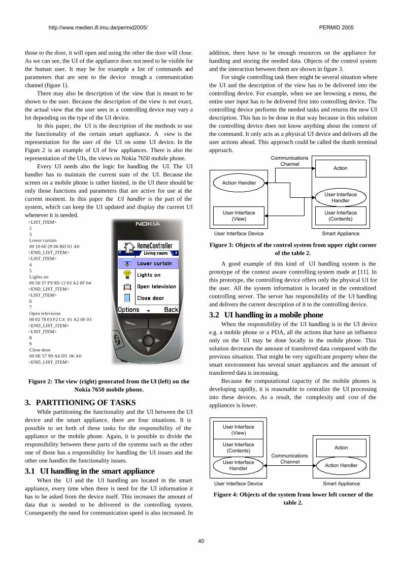
those to the door, it will open and using the other the door will close. As we can see, the UI of the appliance does not need to be visible for the human user. It may be for example a list of commands and parameters that are sent to the device trough a communication channel (figure 1).
There may also be description of the view that is meant to be shown to the user. Because the description of the view is not exact, the actual view that the user sees in a controlling device may vary a lot depending on the type of the UI device.
In this paper, the UI is the description of the methods to use the functionality of the certain smart appliance. A view is the representation for the user of the UI on some UI device. In the Figure 2 is an example of UI of few appliances. There is also the representation of the UIs, the views on Nokia 7650 mobile phone.
Every UI needs also the logic for handling the UI. The UI handler has to maintain the current state of the UI. Because the screen on a mobile phone is rather limited, in the UI there should be only those functions and parameters that are active for use at the current moment. In this paper the UI handler is the part of the system, which can keep the UI updated and display the current UI whenever it is needed.
<LIST_ITEM> 2 3 Lower curtain 00 10 60 29 06 BD 01 A0 <END_LIST_ITEM> <LIST_ITEM> 4 5 Lights on 00 50 37 F9 9D 12 03 A2 0F 04 <END_LIST_ITEM> <LIST_ITEM> 6 7 Open television 00 02 78 03 F2 C4 01 A2 0F 03 <END_LIST_ITEM> <LIST_ITEM> 8 9 Close door 00 0E 57 99 A6 D5 06 A0 <END_LIST_ITEM>
Figure 2: The view (right) generated from the UI (left) on the Nokia 7650 mobile phone.
3. PARTITIONING OF TASKS While partitioning the functionality and the UI between the UI
device and the smart appliance, there are four situations. It is possible to set both of these tasks for the responsibility of the appliance or the mobile phone. Again, it is possible to divide the responsibility between these parts of the systems such as the other one of those has a responsibility for handling the UI issues and the other one handles the functionality issues.
3.1 UI handling in the smart appliance When the UI and the UI handling are located in the smart
appliance, every time when there is need for the UI information it has to be asked from the device itself. This increases the amount of data that is needed to be delivered in the controlling system. Consequently the need for communication speed is also increased. In
addition, there have to be enough resources on the appliance for handling and storing the needed data. Objects of the control system and the interaction between them are shown in figure 3.
For single controlling task there might be several situation where the UI and the description of the view has to be delivered into the controlling device. For example, when we are browsing a menu, the entire user input has to be delivered first into controlling device. The controlling device performs the needed tasks and returns the new UI description. This has to be done in that way because in this solution the controlling device does not know anything about the context of the command. It only acts as a physical UI device and delivers all the user actions ahead. This approach could be called the dumb terminal approach.
User Interface(View)
Action Handler
Action
User Interface Device Smart Appliance
CommunicationsChannel
User InterfaceHandler
User Interface(Contents)
Figure 3: Objects of the control system from upper right corner
of the table 2.
A good example of this kind of UI handling system is the prototype of the context aware controlling system made at [11]. In this prototype, the controlling device offers only the physical UI for the user. All the system information is located in the centralized controlling server. The server has responsibility of the UI handling and delivers the current description of it to the controlling device.
3.2 UI handling in a mobile phone When the responsibility of the UI handling is in the UI device
e.g. a mobile phone or a PDA, all the actions that have an influence only on the UI may be done locally in the mobile phone. This solution decreases the amount of transferred data compared with the previous situation. That might be very significant property when the smart environment has several smart appliances and the amount of transferred data is increasing.
Because the computational capacity of the mobile phones is developing rapidly, it is reasonable to centralize the UI processing into these devices. As a result, the complexity and cost of the appliances is lower.
User Interface(View)
User Interface(Contents)
User InterfaceHandler Action Handler
Action
User Interface Device Smart Appliance
CommunicationsChannel
Figure 4: Objects of the system from lower left corner of the
table 2.
http://www.medien.ifi.lmu.de/permid2005/ PERMID 2005
40
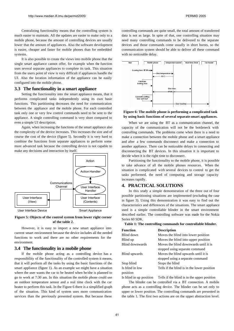
Centralizing functionality means that the controlling system is much easier to maintain. All the updates are easier to make only to a mobile phone, because the amount of controlling devices are usually lower that the amount of appliances. Also the software development is easier, cheaper and faster for mobile phones than for embedded systems.
It is also possible to create the views into mobile phone that the single smart appliance cannot offer, for example when the function uses several separate appliances to complete its task. This situation from the users point of view is very difficult if appliances handle the UI. Also the location information of the appliance can be easily configured into the mobile phone.
3.3 The functionality in a smart appliance Setting the functionality into the smart appliance means, that it
performs complicated tasks independently using its own basic functions. This partitioning decreases the need for communication between the appliance and the mobile phone. For each controlled task only one or very few control commands need to be sent to the appliance. A single controlling command is very short compared to even a simple UI description.
Again, when increasing the functions of the smart appliance also the complexity of the device increases. This increases the size and of course the cost of the device (figure 5). Secondly it is very hard to combine the functions from separate appliances to perform some more advanced task because the controlling device is not capable to make any decisions and interaction by itself.
User Interface(View)
Action Handler
Action
User Interface Device Smart Appliance
CommunicationsChannel User Interface
Handler
User Interface(Contents)
Figure 5: Objects of the control system from lower right corner
of the table 2.
However, it is easy to import a new smart appliance into current smart environment because the device includes all the needed functions to work and there are no other requirements for the environment.
3.4 The functionality in a mobile phone If the mobile phone acting as a controlling device has a
responsibility of the functionality of the controlled system it means, that it will perform all the tasks by using the basic functions of the smart appliance (figure 1). As an example we might have a situation where the user wants the car to be heated when he/she is planned to go to work at 7:30 am. In this situation the mobile phone could use an outdoor temperature sensor and a real time clock with the car heater to perform this task. In the Figure 6 there is a simplified graph of the situation. This kind of system uses more communication services than the previously presented system. But because these
controlling commands are quite small, the total amount of transferred data is not as large. In spite of that, one controlling situation may need many controlling commands to be delivered to the separate devices and those commands come usually in short bursts, so the communication system should be able to deliver all these command with no noticeable delay.
Figure 6: The mobile phone is performing a complicated task by using basic functions of several separate smart appliances.
When we are using the BT as a communication channel, the capacity of the communication will not be the bottleneck with controlling commands. The problems come when there is a need to make a connection between the mobile phone and a smart appliance and after a few commands disconnect and make a connection to another appliance. There can be noticeable delays in connecting and disconnecting the BT devices. In this situation it is important to decide when it is the right time to disconnect.
Partitioning the functionality to the mobile phone, it is possible to take advance of all the mobile phones resources. When the situation is complicated with several devices to control to get the tasks performed, the need of computing and storage capacity increases rapidly.
4. PRACTICAL SOLUTIONS In this study a simple demonstration of the three out of four
possible partitioning situations are implemented (excluding the case in figure 3). Using this demonstration it was easy to find out the characteristics and differences of the situations. The smart appliance used is a simple controllable blinder in the smart environment described earlier. The controlling software was made for the Nokia Series 60 SDK.
Table 1: The controlling commands for controllable blinder.
Function Description Blind down Moves the blind into lower position Blind up Moves the blind into upper position Blind downwards Moves the blind downwards until it is
stopped using separate command Blind upwards Moves the blind upwards until it is
stopped using a separate command Stop blind Stops the blind Is blind in low position
Tells if the blind is in the lower position
Is blind in up position Tells if the blind is in the upper position The blinder can be controlled via a BT connection. A mobile
phone acts as a controlling device. The blinder can be set only to upper or lower position. The controlling commands are presented in the table 1. The first two actions are on the upper abstraction level.
http://www.medien.ifi.lmu.de/permid2005/ PERMID 2005
41
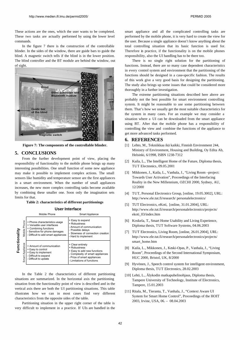
These actions are the ones, which the user wants to be completed. These two tasks are actually performed by using the lower level commands.
In the figure 7 there is the construction of the controllable blinder. In the sides of the window, there are guide bars to guide the blind. A magnetic switch tells if the blind is in the lower position. The blind controller and the BT module are behind the window, out of sight.
Figure 7: The components of the controllable blinder.
5. CONCLUSIONS From the further development point of view, placing the
responsibility of functionality to the mobile phone brings up many interesting possibilities. One small function of some new appliance may make it possible to implement complex actions. The small sensors like humidity and temperature sensor are the first appliances in a smart environment. When the number of small appliances increases, the new more complex controlling tasks become available by combining these smaller one. Soon only the imagination sets limits for that.
Table 2: characteristics of different partitionings
Mobile Phone Smart Appliance
User Interface
Mob
ile P
hone
Sm
art A
pplia
nce
Func
tiona
lity
+ Phone characteristics usage+ Versatile user interfaces+ Combining functions- Sensitive for phone damages- Difficult to add smart appliances
+ Easy to expand+ Robustness- Amount of communication- Possible delays- Slowness of connection creation- Hard to implement
+ Amount of communication+ Easy to control+ Easy to implement- Difficult to expand- Difficult to update
+ Clear entirety+ Robustness+ Easy to add new functions- Complexity of smart appliances- Prize of smart appliances- Limitations of functions
In the Table 2 the characteristics of different partitioning situations are summarized. In the horizontal axis the partitioning situation from the functionality point of view is described and in the vertical axis there are both the UI partitioning situations. This table illustrates how we can in most cases find very different characteristics from the opposite sides of the table.
Partitioning situation in the upper right corner of the table is very difficult to implement in a practice. If UIs are handled in the
smart appliance and all the complicated controlling tasks are performed by the mobile phone, it is very hard to create the view for the user. Because a single appliance doesn’t know anything about the total controlling situation that its basic function is used for. Therefore in practice, if the functionality is on the mobile phones responsibility, also the UI handling has to be there too.
There is no single right solution for the partitioning of functions. Instead, there are so many case dependent characteristics in every control system and environment that the partitioning of the functions should be designed in a case-specific fashion. The results of this work give a very good basis for designing the partitioning. The study also brings up some issues that could be considered more thoroughly in a further investigation.
The extreme partitioning situations described here above are probably not the best possible for smart environment controlling system. It might be reasonable to use some partitioning between them. That’s how we usually get the most suitable characteristics for the system in many cases. For an example we may consider a situation where a UI can be downloaded from the smart appliance using BT. After that the mobile phone has a responsibility of controlling the view and combine the functions of the appliance to get more advanced tasks performed.
6. REFERENCES [1] Lehto, M., Tekniikkaa ikä kaikki, Finnish Environment 244,
Ministry of Environment, Housing and Building, Oy Edita Ab, Helsinki, 6/1998, ISBN 1238-7312
[2] Kaila, L., The Intelligent Home of the Future, Diploma thesis, TUT Electronics, 09.05.2001
[3] Mikkonen, J., Kaila, L., Vanhala, J., “Living Room –project: Towards User Activation”, Proceedings of the Interfacing Reality in the New Millennium, OZCHI 2000, Sydney, AU, 12/2000
[4] TUT, Personal Electronics Group, [online, 19.05.3002], URL: http://www.ele.tut.fi/research/ personalelectronics/
[5] TUT Electronics, eKoti, [online, 31.01.2004], URL: http://www.ele.tut.fi/research/personalelectronics/projects/ ekoti_03/index.htm
[6] Koskela, T., Smart Home Usability and Living Experience, Diploma thesis, TUT Software Systems, 04.06.2003
[7] TUT Electronics, Living Room, [online, 26.01.2004], URL: http://www.ele.tut.fi/research/personalelectronics/projects/ smart_home.htm
[8] Kaila, L., Mikkonen, J., Keski-Opas, P., Vanhala, J., “Living Room”, Proceedings of the Second International Symposium, HUC 2000, Bristol, UK, 8/2000
[9] Hyvönen, J., Speech control system for intelligent environment, Diploma thesis, TUT Electronics, 28.02.2003
[10] Lehti, L., Älykodin matkapuhelinohjaus, Diploma thesis, Tampere University of Technology, Institute of Electronics, Tampere, 15.01.2003
[11] Ritala, M., Tieranta, T., Vanhala, J., “Context Aware UI System for Smart Home Control”, Proceedings of the HOIT 2003, Irvine, USA, 06. – 08.04.2003
http://www.medien.ifi.lmu.de/permid2005/ PERMID 2005
42
Exploring Mobile Phone Interaction with Situated Displays Keith Cheverst, Alan Dix, Daniel Fitton, Chris Kray, Mark Rouncefield,
George Saslis-Lagoudakis, Jennifer G. Sheridan Department of Computing, Infolab21
Lancaster University +44(0)1524 510312
{kc, dixa, df, kray, rouncefieldm, saslisla, sheridaj}@comp.lancs.ac.uk
ABSTRACT One of the most promising possibilities for supporting user interaction with public displays is the use of personal mobile phones. Furthermore, by utilising Bluetooth users should have the capability to interact with displays without incurring personal financial connectivity costs. However, despite the relative maturity of Bluetooth as a standard and the widespread adoption in today’s mobile phones market little exploration seems to have taken place in this area despite its apparent significant potential.
Keywords Situated displays, Bluetooth, Mobile Phones, Interaction, Prototyping.
1. INTRODUCTION One exciting avenue for supporting user interaction with situated/public displays is the use of personal mobile phones. ‘Historically’, one obvious drawback of using mobile phones has been cost, however, by utilising Bluetooth (or its successor protocol) users should have the capability to interact without incurring personal financial connectivity costs. However, despite the relative maturity of Bluetooth as a standard (it was actually standardized in 1996) and its widespread adoption in today’s mobile phones little exploration seems to have taken place in this area despite its apparent significant potential.
In this paper we introduce our current work on exploring this area. The work described is being carried out under the auspices of the EPSRC funded CASIDE project (Investigating Cooperative Applications in Situated Display Environments, see: www.caside.lancs.ac.uk/ for further details).
2. CURRENT EXPERIMENTS – SITUATED DISPLAY DEPLOYMENTS In the last three years we have deployed a small but significant number of situated displays within the Computing Department of Lancaster University. When we refer to such situated displays we agree strongly with the definition provided by O’Hara [8]:
In recent years, more and more information is being presented on dedicated digital displays situated at particular locations within our environment. At their most basic, digital display technologies allow information to be more easily updated dynamically and remotely. However, these new kinds of interaction technologies also allow people to use these situated displays in novel ways both as for the individual’s purposes and in the support of group work. (O’Hara et al. 2002).
The following two subsections describe two of these existing deployments and our initial experiments to investigate how Bluetooth technology might provide new and useful ways for users to interact with the deployed displays using their own personal mobile phones.
2.1 Interaction with Office Door Displays The first Hermes door display (see figure 1) was installed outside one of the offices in Lancaster’s Computing department in March 2002 and by October 2003 the number of deployed units had increased to ten. Unfortunately a move of building meant that the Hermes system (see [4] and Chapter 6 of [9] for more details) had to be dismantled but during the 24 months of its use 775 notes were left by visitors and over 5278 messages were set by owners.
Figure 1: An early Hermes display.
The system is currently being redeployed in the new office building and we are currently experimenting with new design ideas. For example, in the initial Hermes system each office only had one display - we are trialling the use of two displays per office. This would allow one display specifically for supporting interaction with the visitor to an office, e.g. enabling the visitor to leave a note for the owner. The other display would be solely for the owner leaving messages to visitors.
One concern with the original system was security – we did have 2 units stolen outside of office hours. One potential benefit of Bluetooth is that users can interact with the system, e.g. to leave a note for the owner of the door display, while the display is more safely secured within the office.
Currently it is envisaged that visitors will be able to use the system in order to download, via Bluetooth, information from the office door display such as the owner’s contact details. However, studies have shown that owners are prepared to share certain information when a student has made the journey to their office which they would not necessarily make available on, for example, their web home page. We plan to investigate this issue more fully and ascertain whether the owner of a door display is prepared to share and make available objects such as calendar details based
http://www.medien.ifi.lmu.de/permid2005/ PERMID 2005
43
on the scoping effect resulting from the limited range of the Bluetooth signal – in effect restricting the availability of such information to persons that are within close proximity to her actual office (see figure 2a). Figure 2b shows the kind of message that could be ‘scribbled’ and then sent by an owner or visitor using a mobile phone equipped with a touch screen.
Figure 2a (left): Visitor using his mobile phone to interact with a Hermes display, and, figure 2b (right) the kind of
display that could be composed using the jotter app found on touch-screen based phones such as the Sony-Ericsson p800.
2.2 Interaction with Public Photo Display We first deployed the Hermes picture display in June 2003. The system is effectively an extension to the Hermes system and was first designed to enable users on a particular corridor to send pictures through MMS, e-mail etc.(see figure 3a) - in the subject header of the message the user would stipulate the location of the display, e.g. “PUB LOC C FLOOR”. The display is actually a Phillips ‘smart’ display and in addition to displaying a picture presentation the system was recently extended to support a presentation to show the vCards of users that have ‘registered’ with the display (see figure 3b).
Figure 3a (left): the Hermes Picture Display showing the
picture presentation, and 3b (right) showing the registered users’ contact details presentation.
Clearly with MMS we already support some level of interaction with the photo display – but we are currently experimenting with ways in which users can interact when co-located with the display via a Bluetooth connection to their mobile phone. To this end we are investigating a range of interaction and user interface ideas.
2.2.1 Asynchronous Interaction A user can use the built-in application on his or her mobile phone in order to send or receive a picture or contact details in vCard format (RFC 2425) from the photo display over Bluetooth.
Figure 4 below illustrates the photo display and a user sending a file (in this case it happens to be a picture) via their phone to the display. As a prerequistite to sending a file the user must firstly pair with the display - this involves searching for the display (see
figure 5a) and then entering the appropriate pass key (note that details of this appear in the centre of the presentation).
Figure 4: Visitor using his mobile phone to interact with the
Hermes Picture Display using Bluetooth. In order to select a picture or vCard for download onto a mobile phone a variety of approached are possible. For example, a registered user may simply touch the display to select a picture or vCard and then select their (discoverable) Bluetooth phone from a list in order to initiate the transfer.
Figure 5a (left): Visitor waiting to pair with the public display, and, figure 5b (right) user accepting to receive
selected vCard file. However, requiring a user to touch the screen necessarily restricts the number of users that can select a picture concurrently (however, in practice this might provide an interesting opportunity for social engagement!). So with the aim to investigate how we might support a group of users interacting with the display (for example during a departmental research open-day) we are also considering more synchronous interaction approaches. Note that at this stage we are considering how to support simultaneous interaction with a small group (i.e. of no more than 8 people) – clearly other approaches would be required to support scalability up to an arbitrary number of users but it is certainly not clear that such scalability is required at this stage nor that such highly scalable solutions would be appropriate for the smaller sized group numbers envisaged for this particular deployment.
2.2.2 Synchronous Interaction A number of approaches are possible, some more engaging and visible than others and it is our intention in the coming weeks to carry out (initially) simple user studies in order to find which methods users prefer. The remainder of this section considers the selection and download of vCards from the display.
http://www.medien.ifi.lmu.de/permid2005/ PERMID 2005
44
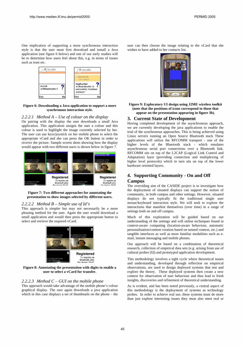
One implication of supporting a more synchronous interaction style is that the user must first download and install a Java application (see figure 6 below) and one of our early studies will be to determine how users feel about this, e.g. in terms of issues such as trust etc.
Figure 6: Downloading a Java application to support a more synchronous interaction style.
2.2.2.1 Method A – Use of colour on the display On pairing with the display the user downloads a small Java application. This application assigns the user a colour and this colour is used to highlight the image currently selected by her. The user can use keys/joystick on her mobile phone to select the appropriate vCard and she can press the OK button in order to receive the picture. Sample screen shots showing how the display would appear with two different users is shown below in figure 7.
Figure 7: Two different approaches for annotating the presentation to show images selected by different users.
2.2.2.2 Method B – Simple use of Id’s This approach is simpler but may not necessarily be a more pleasing method for the user. Again the user would download a small application and would then press the appropriate button to select and retrieve the required vCard.
Figure 8: Annotating the presentation with digits to enable a
user to select a vCard for transfer.
2.2.2.3 Method C – GUI on the mobile phone This approach would take advantage of the mobile phone’s colour graphical display. The user again downloads a java application which in this case displays a set of thumbnails on the phone – the
user can then choose the image relating to the vCard that she wishes to have added to her contacts list.
Figure 9: Exploratory UI design using J2ME wireless toolkit (note that the positions of icons correspond to those that
appear on the presentation appearing in figure 3b).
3. Current State of Development Having completed development of the asynchronous approach, we are currently developing the java applications to enable the trial of the synchronous approaches. This is being achieved using Linux servers running an Open Source Bluetooth stack These applications will utilize the RFCOMM transport - one of the higher levels of the Bluetooth stack - which emulates asynchronous serial port connections over a Bluetooth link. RFCOMM sits on top of the L2CAP (Logical Link Control and Adaptation) layer (providing connection and multiplexing of higher level protocols) which in turn sits on top of the lower hardware oriented layers.
4. Supporting Community - On and Off Campus The overriding aim of the CASIDE project is to investigate how the deployment of situated displays can support the notion of community, in both campus and other settings. However, situated displays do not typically fit the traditional single user mouse/keyboard interaction style. We will seek to explore the interactions that manifest themselves (over time) in a range of settings both on and off campus. Much of this exploration will be guided based on our understanding of the settings and will utilise techniques found in context-aware computing (location-aware behaviour, automatic personalisation/content creation based on sensed context, etc.) and tangible interfaces as well as more familiar modalities such as e-mail, instant messaging and mobile phones. Our approach will be based on a combination of theoretical research, collection of empirical data sets (e.g. arising from use of cultural probes [6]) and prototyped application development.
This methodology involves a tight cycle where theoretical issues and understanding, developed through reflection on empirical observations, are used to design deployed systems that test and explore the theory. These deployed systems then create a new context for observation of user behaviour and thus lead to fresh insights, discoveries and refinement of theoretical understanding. As is evident, and has been noted previously, a central aspect of this methodology is the deployment of systems as technology probes. In order to achieve real use, these systems must do more than just explore interesting issues they must also meet real or
http://www.medien.ifi.lmu.de/permid2005/ PERMID 2005
45
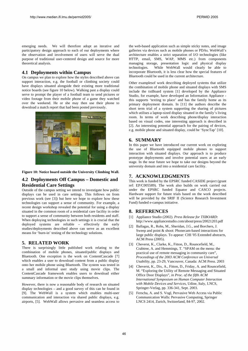
emerging needs. We will therefore adopt an iterative and participatory design approach to each of our deployments where the observation and involvement of users will serve the dual purpose of traditional user-centered design and source for more theoretical analysis.
4.1 Deployments within Campus On campus we plan to explore how the styles described above can support interaction, e.g. the football or climbing society could have displays situated alongside their existing more traditional notice boards (see figure 10 below). Walking past a display could serve to prompt the player of a football team to send pictures or video footage from their mobile phone of a game they watched over the weekend. He or she may then use their phone to download a match report that had been posted previously.
Figure 10: Notice board outside the University Climbing Wall.
4.2 Deployments Off Campus – Domestic and Residential Care Settings Outside of the campus setting we intend to investigate how public displays can be used in care settings. This follows on from previous work (see [3]) but here we hope to explore how these technologies can support a sense of community. For example, a recent design workshop revealed the potential for using a display situated in the common room of a residential care facility in order to support a sense of community between both residents and staff. When deploying technologies in such settings it is crucial that the deployed systems are reliable – effectively the early studies/deployments described above can serve as an excellent means for ‘burn-in’ testing of the technology solutions.
5. RELATED WORK There is surprisingly little published work relating to the combination of mobile phones, situated/public displays and Bluetooth. One exception is the work on ContentCascade [7] which enables a user to download content from a public display onto her mobile phone using Bluetooth. The system was tested in a small and informal user study using movie clips. The ContentCascade framework enables users to download either summary information or the movie clips themselves.
However, there is now a reasonable body of research on situated display technologies – and a good survey of this can be found in [9]. The WebWall is a system which enables multi-user communication and interaction via shared public displays, e.g. airports, [5]. WebWall allows pervasive and seamless access to
the web-based application such as simple sticky notes, and image galleries via devices such as mobile phones or PDAs. WebWall’s architecture enables a strict separation of I/O technologies (like HTTP, email, SMS, WAP, MMS etc.) from components managing storage, presentation logic and physical display technologies. While WebWall would clearly be able to incorporate Bluetooth, it is less clear how the special features of Bluetooth could be used in the current architecture.
Other examplesof work describing deployed systems that utilize the combination of mobile phone and situated displays with SMS include the txtBoard system [1] developed by the Appliance Studio, for example, have developed an Information Appliance - this supports ‘texting to place’ and has the family home as its primary deployment domain. In [11] the authors describe the short term trial of a system supporting the sharing of pictures which utilises a laptop-sized display situated in the family’s living room. In terms of work describing phone/display interaction based on visual codes, one interesting approach is described in [2]. An interesting potential approach for the pairing of devices, e.g. mobile phone and situated display, could be ‘SyncTap’ [10].
6. SUMMARY In this paper we have introduced our current work on exploring the use of Bluetooth equipped mobile phones to support interaction with situated displays. Our approach is to produce prototype deployments and involve potential users at an early stage. In the near future we hope to take our designs beyond the university domain and into a residential care facility.
7. ACKNOWLEDGMENTS This work is funded by the EPSRC funded CASIDE project (grant ref: EP/C005589). The work also builds on work carried out under the EPSRC funded Equator and CASCO projects. Hardware support for future trials based on the work described will be provided by the SRIF II (Science Research Investment Fund) funded e-campus initiative.
8. REFERENCES [1] Appliance Studio (2002). Press Release for TXBOARD:
http://www.appliancestudio.com/about/press/20021203.pdf [2] Ballagas, R., Rohs, M., Sheridan, J.G., and Borchers, J.
Sweep and point & shoot: Phonecam-based interactions for large public displays. To appear: CHI '05 Extended abstracts, ACM Press (2005).
[3] Cheverst, K., Clarke, K., Fitton, D., Rouncefield, M., Crabtree, A. and Hemmings, T. “SPAM on the menu: the practical use of remote messaging in community care”, Proceedings of the 2003 ACM Conference on Universal Usability, pp. 23-29, Vancouver, Canada: ACM Press. 2003
[4] Cheverst, K., Dix, A., Fitton, D., Friday, A. and Rouncefield, M. “Exploring the Utility of Remote Messaging and Situated Office Door Displays”, in Proc. of the fifth ACM International Symposium on Human Computer Interaction with Mobile Devices and Services, Udine, Italy, LNCS, Springer-Verlag, pp. 336-341, Sept. 2003.
[5] Ferscha, A. and S. Vogl, Pervasive Web Access via Public Communication Walls: Pervasive Computing, Springer LNCS 2414, Zurich, Switzerland, 84-97, 2002.
http://www.medien.ifi.lmu.de/permid2005/ PERMID 2005
46
[6] Gaver, W., Dunne, A., Pacenti, E. Design: Cultural Probes, in Interactions: New Visions of Human-Computer Interaction. 6(1), pp. 21-29. (1999).
[7] Himanshu Raj, R. Gossweiler, D. Milojicic, “ContentCascade Incremental Content Exchange between Public Displays and Personal Devices”, in Proc. of the firsy Annual International Conference on Mobile and Ubiquitous Systems: Networking and Services (MobiQuitous'04), Boston, Massachussets, USA, 374-381, 2004.
[8] O’Hara, K. E. Churchill, M. Perry, D. Russell, N. A. Streitz, Public, Community and Situated Displays: Design, Use and Interaction around Shared Information Displays, www.appliancestudio.com/cscw/cscwdisplayworkshopcall.htm (2002).
[9] O’Hara, K. M. Perry, et al Public and Situated Displays: Social and Interactional aspects of shared display technologies, Kluwer. ISBN 1-4020-1677-8. 2003.
[10] Rekimoto, J. Ayatsuka, Y., Kohno, M. “SyncTap: An Interaction Technique for Mobile Networking”, in Proc. of the fifth ACM International Symposium on Human Computer Interaction with Mobile Devices and Services, Udine, Italy, LNCS, Springer-Verlag, pp 104-115, 2003.
[11] Romero, N., Baren, J. v., Markopoulos, P., Ruyter, B. d. and IJsselsteijn, W. Addressing Interpersonal Communication Needs through Ubiquitous Connectivity: Home and Away, in Proc. of European Symposium on Ambient Intelligence, pp. 419-429. 2003.
http://www.medien.ifi.lmu.de/permid2005/ PERMID 2005
47
Motion Detection as Interaction Technique for Games &Applications on Mobile Devices
Stephan A. DrabUpper Austria University of Applied Sciences
Mobile ComputingHauptstrasse 117
Hagenberg, Austria
Nicole M. ArtnerUpper Austria University of Applied Sciences
Media Technology and DesignHauptstrasse 117
Hagenberg, Austria
Keywordsmobile devices, pervasive, interaction techniques, motion de-tection
ABSTRACTMobile devices become smaller and more powerful with eachgeneration distributed. Because of the tiny enclosures theinteraction with such devices offers limited input capabili-ties. In contrast there are hardly any mobile phones pur-chasable that do not have a built-in camera. We developeda concept of an intuitive interaction technique using opticalinertial tracking on mobile phones. The key of this con-cept is the user moving the mobile device which results ina moving video stream of the camera. The direction of themovement can be calculated with a suitable algorithm. Thispaper outlines the algorithm Projection Shift Analysis devel-oped to run on mobile phones.
1. MOTIVATIONOur approach detects the relative motion of the camera inthe two-dimensional pixel space of the image. As cameramovement directly results in motion of all scene componentsthe motion of the camera movement can be defined as theinverse movement of the scene. If there are no significantscene components moving for itself conventional motion de-tection methods can be used to analyse the video stream.There are several algorithms from different fields of com-puter graphics and image processing used to parameterisethe motion of the scene. Although they pursue differentapproaches, all of them would analyse the scene motion suf-ficiently. Due to low CPU and memory resources on mobilephones we developed the Projection Shift Analysis algorithmfor motion analysis. There is a wide range of applicationsfor the motion parameter, for example controlling a gamesimilar to joystick interaction. Another possible applicationcould interpret motion gestures or control the cursor like thestylus input technique on PDAs.
2. RELATED WORKIn [8] Geiger et al. present concepts for mobile games andaddress interaction issues concerning mobile devices.
The simplest approach to track objects is detecting signif-icant features in an image, e.g. edges. Naturally, edge de-tection methods like the Robert, Prewitt, Sobel, Laplace orCanny [2] filters are used to achieve this.
Motion Detection in 3D-Computer Graphics, Mixed- andAugmented Reality is often referred to as Tracking. Beieret al. presented a markerless tracking system using edge de-tection in [1]. Comport et al. propose a robust marker-less tracking system in [3]. A specialised solution to theproblem of markerless tracking was published by Simon etal. in [15]. In [11] Moehring et al. present a marker-basedtracking system designed especially for mobile phones. Katoand Billinghurst developed the optical marker based track-ing system ARToolKit published in [9].
Foxlin et al. present a wide spectrum of optical inertial track-ing systems in [5, 6, 17]. Additionally, a taxonomy of MotionDetection methods has been published in [4]. In [10] Kollerpresents a method to track the position of cars using anoptical system.
Siemens Mobile developed a game called Mozzies, that isdistributed with the mobile phone SX1 by default. ThisSymbian based game augments the background video fromthe camera with moths. The user can point the gun at amoth and shoot it by moving the phone and pressing theappropriate button. In [7] Geiger et al. present an inter-esting approach of an augmented reality version of a soccergame running on a PDA.
3. INTERACTION TECHNIQUESThis chapter describes and classifies various interaction tech-niques used on mobile devices nowadays. There are a fewmain parameters that define the usability of those tech-niques. The reaction time between the user input andthe response on output devices such as the display is a verycrucial parameter. Any visual response on the output deviceafter about 200 ms is not interpreted as a direct reaction tothe user, but as a separate event. The quantity of actionsa user is able to perform using a specific input technique de-fines the speed at which he can interact with the device. Theintuitivity of an input method strongly affects the usability
http://www.medien.ifi.lmu.de/permid2005/ PERMID 2005
48
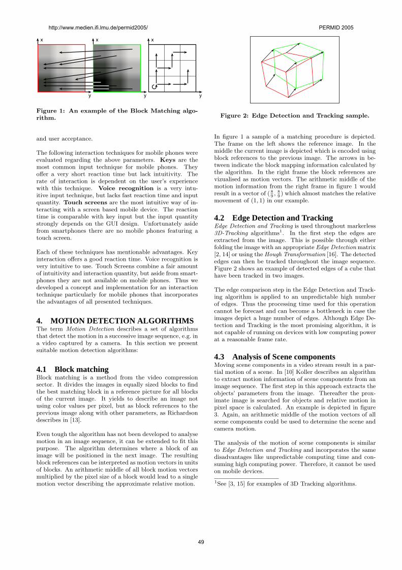
x
y
x
y
x
y
Figure 1: An example of the Block Matching algo-rithm.
and user acceptance.
The following interaction techniques for mobile phones wereevaluated regarding the above parameters. Keys are themost common input technique for mobile phones. Theyoffer a very short reaction time but lack intuitivity. Therate of interaction is dependent on the user’s experiencewith this technique. Voice recognition is a very intu-itive input technique, but lacks fast reaction time and inputquantity. Touch screens are the most intuitive way of in-teracting with a screen based mobile device. The reactiontime is comparable with key input but the input quantitystrongly depends on the GUI design. Unfortunately asidefrom smartphones there are no mobile phones featuring atouch screen.
Each of these techniques has mentionable advantages. Keyinteraction offers a good reaction time. Voice recognition isvery intuitive to use. Touch Screens combine a fair amountof intuitivity and interaction quantity, but aside from smart-phones they are not available on mobile phones. Thus wedeveloped a concept and implementation for an interactiontechnique particularly for mobile phones that incorporatesthe advantages of all presented techniques.
4. MOTION DETECTION ALGORITHMSThe term Motion Detection describes a set of algorithmsthat detect the motion in a successive image sequence, e.g. ina video captured by a camera. In this section we presentsuitable motion detection algorithms:
4.1 Block matchingBlock matching is a method from the video compressionsector. It divides the images in equally sized blocks to findthe best matching block in a reference picture for all blocksof the current image. It yields to describe an image notusing color values per pixel, but as block references to theprevious image along with other parameters, as Richardsondescribes in [13].
Even tough the algorithm has not been developed to analysemotion in an image sequence, it can be extended to fit thispurpose. The algorithm determines where a block of animage will be positioned in the next image. The resultingblock references can be interpreted as motion vectors in unitsof blocks. An arithmetic middle of all block motion vectorsmultiplied by the pixel size of a block would lead to a singlemotion vector describing the approximate relative motion.
Figure 2: Edge Detection and Tracking sample.
In figure 1 a sample of a matching procedure is depicted.The frame on the left shows the reference image. In themiddle the current image is depicted which is encoded usingblock references to the previous image. The arrows in be-tween indicate the block mapping information calculated bythe algorithm. In the right frame the block references arevizualised as motion vectors. The arithmetic middle of themotion information from the right frame in figure 1 wouldresult in a vector of ( 8
9, 8
9) which almost matches the relative
movement of (1, 1) in our example.
4.2 Edge Detection and TrackingEdge Detection and Tracking is used throughout markerless3D-Tracking algorithms1. In the first step the edges areextracted from the image. This is possible through eitherfolding the image with an appropriate Edge Detection matrix[2, 14] or using the Hough Transformation [16]. The detectededges can then be tracked throughout the image sequence.Figure 2 shows an example of detected edges of a cube thathave been tracked in two images.
The edge comparison step in the Edge Detection and Track-ing algorithm is applied to an unpredictable high numberof edges. Thus the processing time used for this operationcannot be forecast and can become a bottleneck in case theimages depict a huge number of edges. Although Edge De-tection and Tracking is the most promising algorithm, it isnot capable of running on devices with low computing powerat a reasonable frame rate.
4.3 Analysis of Scene componentsMoving scene components in a video stream result in a par-tial motion of a scene. In [10] Koller describes an algorithmto extract motion information of scene components from animage sequence. The first step in this approach extracts theobjects’ parameters from the image. Thereafter the prox-imate image is searched for objects and relative motion inpixel space is calculated. An example is depicted in figure3. Again, an arithmetic middle of the motion vectors of allscene components could be used to determine the scene andcamera motion.
The analysis of the motion of scene components is similarto Edge Detection and Tracking and incorporates the samedisadvantages like unpredictable computing time and con-suming high computing power. Therefore, it cannot be usedon mobile devices.
1See [3, 15] for examples of 3D Tracking algorithms.
http://www.medien.ifi.lmu.de/permid2005/ PERMID 2005
49
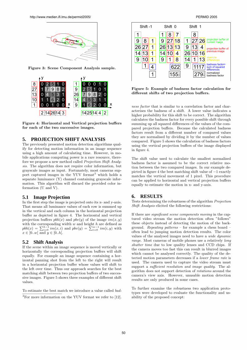
Figure 3: Scene Component Analysis sample.
0 2 5 1 0
1 7 9 8 2
0 4 5 3 1
1 1 6 2 0
0 0 1 0 0
2 142614 3
8
27
13
10
1
1
9
26
14
9
2 5 1 0
7 9 8 2
4 5 3 1
1 6 2 0
0 00 1 0
1
0
1
0
142514 4 2
x
y
x
y
Figure 4: Horizontal and Vertical projection buffersfor each of the two successive images.
5. PROJECTION SHIFT ANALYSISThe previously presented motion detection algorithms qual-ify for detecting motion information in an image sequenceusing a high amount of calculating time. However, in mo-bile applications computing power is a rare resource, there-fore we propose a new method called Projection Shift Analy-sis. The algorithm does not require color information, butgrayscale images as input. Fortunately, most cameras sup-port captured images in the YUV format2 which holds aseparate luminance (Y) channel containing grayscale infor-mation. This algorithm will discard the provided color in-formation (U and V).
5.1 Image ProjectionIn the first step the image is projected onto its x- and y-axis.That means all luminance values of each row is summed upin the vertical and each column in the horizontal projectionbuffer as depicted in figure 4. The horizontal and verticalprojection buffers pbh(x) and pbv(y) of the image im(x, y)with the corresponding width w and height h are defined aspbh(x) =
Ph−1i=0 im(x, i) and pbv(y) =
Pw−1i=0 im(i, y) with
x ∈ [0..w[ and y ∈ [0..h[.
5.2 Shift AnalysisIf the scene within an image sequence is moved vertically orhorizontally the corresponding projection buffers will shiftequally. For example an image sequence containing a hor-izontal panning shot from the left to the right will resultin a horizontal projection buffer whose values will shift tothe left over time. Thus our approach searches for the bestmatching shift between two projection buffers of two succes-sive images. Figure 5 shows three examples of different shiftvalues.
To estimate the best match we introduce a value called bad-
2For more information on the YUV format we refer to [12].
normalized
badness factor
badness factor=
sum of squared
differences
projection buffer of
previous image
projection buffer of
current image
absolute
differences
1
9
26
14
9
8
27
13
10
1
1
1
1
1
4
1
1
9
26
14
9
8
27
13
10
1
18
13
4
8
155
7
26
4
16
13
1
9
26
14
9
8
27
13
10
1
1
4
Shift -1 Shift 0 Shift 1
622 1117
1
2 279
Figure 5: Example of badness factor calculation fordifferent shifts of two projection buffers.
ness factor that is similar to a correlation factor and char-acterises the badness of a shift. A lower value indicates ahigher probability for this shift to be correct. The algorithmcalculates the badness factor for every possible shift throughsumming up all squared differences of the values of the com-pared projection buffers. Because the calculated badnessfactors result from a different number of compared valuesthey are normalised by dividing it by the number of valuescompared. Figure 5 shows the calculation of badness factorsusing the vertical projection buffers of the image displayedin figure 4.
The shift value used to calculate the smallest normalisedbadness factor is assumed to be the correct relative mo-tion between the two compared images. In our example de-picted in figure 4 the best matching shift value of −1 exactlymatches the vertical movement of 1 pixel. This procedurecan be applied to horizontal and vertical projection buffersequally to estimate the motion in x- and y-axis.
6. RESULTSTests determining the robustness of the algorithm ProjectionShift Analysis elicited the following restrictions:
If there are significant scene components moving in the cap-tured video stream the motion detection often ”follows”these objects instead of detecting the motion of the back-ground. Repeating patterns – for example a chess board –often lead to jumping motion detection results. The colorvalues of the analysed images need to have a wide dynamicrange. Most cameras of mobile phones use a relatively longshutter time due to low quality lenses and CCD chips. Ifthe camera moves too fast this can result in blurred imageswhich cannot be analysed correctly. The quality of the de-tected motion parameters decreases if a lower frame rate isused. The camera used to capture the video stream mustsupport a sufficient resolution and image quality. The al-gorithm does not support detection of rotations around thecamera’s view axis. However, unusable motion detectionresults are only produced in some cases.
To further examine the robustness two application proto-types were developed to evaluate the functionality and us-ability of the proposed concept:
http://www.medien.ifi.lmu.de/permid2005/ PERMID 2005
50
Figure 6: The prototypes MAPnavigator and Cam-eraCursor.
MAPnavigator is an application that allows the user toview different maps. The problem in this context is the lowdisplay resolution of mobile phones. Consequently it is notrecommended to scale down a huge map because then theuser is not able to make out important details in the map.The solution to this problem is to divide the map into sev-eral parts. MAPnavigator uses the Projection Shift Analysismotion detection algorithm to seamlessly navigate throughthe map. It is very easy and intuitive to find the requestedpart of the map using the motion detection technique. Theleft part of figure 6 shows a screenshot of the application.
The application CameraCursor was developed to test ifour motion detection algorithm is capable of controlling acursor. The user is able to control the cross cursor by mov-ing around the mobile phone. By pressing and holding theappropriate button the cursor draws lines while moving onthe screen. Additionally the speed of the cursor can be con-figured at run time. An example of the application is shownin the right part of figure 6.
7. CONCLUSIONSThe Projection Shift Analysis algorithm works if none of thegiven cases in section 6 occur. Compared to the algorithmsin section 4 it uses very little CPU and memory resources.Therefore it is ideal to be used on mobile phones. In case thecamera is moved quickly the results may be inaccurate by afew pixels. Using the motion parameters as user interactiondoes not require high exactness for fast movements becausethe user does not have an indication of inaccuracy as long asthe movement displayed on the screen is approximately fol-lowing his motion. However, there are some cases the algo-rithm cannot keep track of the motion and fails completely.This mostly happens when the user quickly moves the cam-era while pointing at dark spots or repeating patterns. Fu-ture implementations are planned to filter out motion noiseusing the Kalman Filter which would also reduce jumpingmotion parameters caused by unfavorable environments.
8. REFERENCES[1] D. Beier, R. Billert, B. Brderlin, D. Stichling, and
B. Kleinjohann. Marker-less vision based tracking formobile augmented reality. In The Second IEEE andACM International Symposium on Mixed andAugmented Reality, pages 258–259. IEEE, Inc., 2003.
[2] J. F. Canny. Finding edges and lines in images.Master’s thesis, MIT, 1983.
[3] Andrew I. Comport, Eric Marchand, and FrancoisChaumette. A real-time tracker for markerless
augmented reality. In The Second IEEE and ACMInternational Symposium on Mixed and AugmentedReality, pages 36–45. IEEE, Inc., 2003.
[4] Eric Foxlin. Handbook of Virtual EnvironmentTechnology, chapter 8, Motion Tracking Requirementsand Technologies. 2002.
[5] Eric Foxlin, Yury Altshuler, Leonid Naimark, andMike Harrington. Flighttracker: A noveloptical/inertial tracker for cockpit enhanced vision. InIEEE/ACM International Symposium on Mixed andAugmented Reality (ISMAR 2004), 2004.
[6] Eric Foxlin and Leonid Naimark. Circular data matrixfiducial system and robust image processing for awearable vision-inertial self-tracker. In JointInternational Immersive Projection Technologies(IPT)/Eurographics Workshop on VirtualEnvironments (EGVE) 2003 Workshop, 2002.
[7] C. Geiger, B. Kleinnjohann, C. Reimann, andD. Stichling. Mobile ar4all. In Proceedings of the IEEEand ACM International Symposium on AugmentedReality (ISAR), 2001.
[8] Christian Geiger, Volker Paelke, and ChristianReimann. Mobile entertainment computing. InTIDSE, pages 142–147, 2004.
[9] H. Kato and M. Billinghurst. Marker tracking andhmd calibration for a video-based augmented realityconferencing system. In proceedings of IEEEInternational Workshop on Augmented Reality, pages125–133, 1999.
[10] Dieter Koller. Detektion, Verfolgung und Klassifikationbewegter Objekte in monokularen Bildfolgen amBeispiel von Strassenverkehrsszenen. Infix, 1992.
[11] M. Moehring, C. Lessig, and O. Bimber. Opticaltracking and video see-through ar on consumer cellphones. In proceedings of Workshop on Virtual andAugmented Reality of the GI-Fachgruppe AR/VR,pages 193–204, 2004.
[12] Wikipedia, the free encyclopedia. YUV.http://en.wikipedia.org/wiki/YUV.
[13] Iain E. G. Richardson. Video Codec Design:Developing Image and Video Compression Systems.Wiley, June 2002.
[14] J. Shen and S. Castan. An optimal linear operator forstep edge detection. Computer Vision, Graphics andImage Processing, (54), 1992.
[15] Gilles Simon, Andrew W. Fitzgibbon, and AndrewZisserman. Markerless tracking using planar structuresin the scene. In Proc. of ISAR.
[16] Sargur N. Srihari. Analysis of textual images using thehough transformation. Technical report, StateUniversity of New York at Buffalo, 1988.
[17] Dean Wormell and Eric Foxlin. Vis-tracker: Awearable vision-inertial self-tracker. In JointInternational Immersive Projection Technologies(IPT)/Eurographics Workshop on VirtualEnvironments (EGVE) 2003 Workshop, 2003.
http://www.medien.ifi.lmu.de/permid2005/ PERMID 2005
51
Context Modeling for Device- and Location-Aware Mobile Web Applications
Michael Hinz Zoltán Fiala Dresden University of Technology, Department of Computer Science
Heinz-Nixdorf Endowed Chair for Multimedia Technology D-01062, Germany, +49-351-463-38516
{michael.hinz, zoltan.fiala}@inf.tu-dresden.de
ABSTRACT Ubiquitous Web systems have to deal with varying context information in order to support context awareness. Accomplishing this requirement necessitates gathering, processing and representing that information, so that it can be used for adapting Web applications. In this paper we propose a mechanism for modeling dynamically changing context information like user’s device capabilities and location. Furthermore we show how this modeling mechanism can be integrated into context-aware system architectures. With the aid of this approach we are able to perform a device- and location-aware online document generation of Web documents for mobile appliances.
Categories and Subject Descriptors H.5.4 [Hypertext/Hypermedia]: Architectures. H.3.4 [Systems and Software]: User profiles and alert services.
General Terms Management, Measurement, Design.
Keywords Context modeling, context-awareness, device independence, ubiquitous computing, location-based services
1. INTRODUCTION Today’s WWW emerges to a medium of communication and cooperation. A multiplicity of users with different requirements uses the Web as a ubiquitous information store. In this way several trends such as personalization [1] and device independence [2] have raised that require the adjustment of Web applications to the user and its client device. Furthermore, with the emergence of location-based services, the client location becomes important context information, too. Still, today’s location-based services (e.g. navigation system, location-aware museum guides) are fast-paced but usually stand alone applications not suited for the common Web. Furthermore their development is primarily driven by the mobile telecommunication industry and is therefore limited to applications on mobile phones. We claim that the main reason for this shortcoming is the still lacking support for automatically gathering and representing device and location context data. By improving the access to such context information the richness of communication in human-computer interaction increases, and makes it possible to produce more useful Web services [6]. To meet this challenge, this paper introduces context modeling mechanisms which enable the
development of personalized device- and location-aware Web applications at the same time.
The paper is structured as follows. After addressing general context modeling aspects (section 2), modeling mechanisms for device capabilities (section 2.1) and the user’s location (section 2.2) are illustrated. Beyond that, methods and techniques for sensing and representing that context information are presented. The described mechanisms were successfully integrated into a Web system performing a dynamic generation of context-aware Web pages (section 3).
2. CONTEXT MODELING In the literature several definitions of the terms context and context-awareness can be found (e.g. [3], [4]). However, adding context to Web applications requires on the one hand the acquiring and modeling of context information such as location [5] as well as device context [2]. On the other hand that information has to be stored in a standardized representation. Without this application developers are left to develop ad hoc and limited schemes for storing and updating context information. However, the evolution of more sophisticated representations enabling a wider range of capabilities and a true separation of sensing context from the programmable reaction to that context is still an unsolved challenge [6]. To ensure this, the proposed modeling mechanisms represent the gathered information in a profile-based extensible context model ([14]) which relies on the W3C standard CC/PP [7]. Modeling components (e.g. for device, location and user modeling) guarantee a permanent monitoring of context and updating of the corresponding context profiles.
2.1 Device Modeling Because of the requirements of mobile phones and resource restricted handheld computers their in- and output interfaces are limited e.g. in display size or number of buttons. Therefore they are far away from suitable interfaces to the Internet. Overcoming this burden requires the creation and publication of content that is tailored to users’ platform capabilities and dynamically changing device properties. Therefore device capabilities have to be acquired, represented and provided to the document generation engine in the context aware system. In the next chapters those aspects will be explained more detailed.
http://www.medien.ifi.lmu.de/permid2005/ PERMID 2005
52
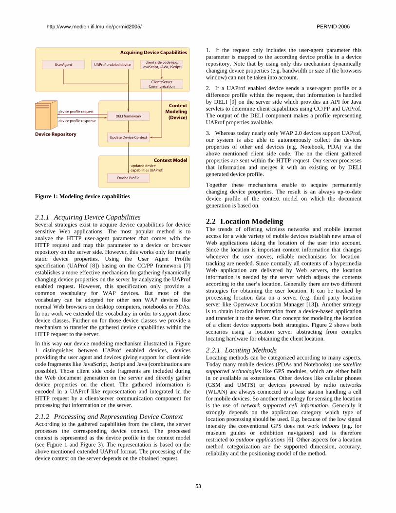
Context Model
Acquiring Device Capabilities
Device Profile
ContextModeling
(Device)DELI framework
updated device capabilities (UAProf)
UserAgent
Update Device Context
client side code (e.g. JavaScript, JAVA, JScript)
Client/Server Communication
device profile request
device profile response
Device Repository
UAProf enabled device
Figure 1: Modeling device capabilities
2.1.1 Acquiring Device Capabilities Several strategies exist to acquire device capabilities for device sensitive Web applications. The most popular method is to analyze the HTTP user-agent parameter that comes with the HTTP request and map this parameter to a device or browser repository on the server side. However, this works only for nearly static device properties. Using the User Agent Profile specification (UAProf [8]) basing on the CC/PP framework [7] establishes a more effective mechanism for gathering dynamically changing device properties on the server by analyzing the UAProf enabled request. However, this specification only provides a common vocabulary for WAP devices. But most of the vocabulary can be adopted for other non WAP devices like normal Web browsers on desktop computers, notebooks or PDAs. In our work we extended the vocabulary in order to support those device classes. Further on for those device classes we provide a mechanism to transfer the gathered device capabilities within the HTTP request to the server. In this way our device modeling mechanism illustrated in Figure 1 distinguishes between UAProf enabled devices, devices providing the user agent and devices giving support for client side code fragments like JavaScript, Jscript and Java (combinations are possible). Those client side code fragments are included during the Web document generation on the server and directly gather device properties on the client. The gathered information is encoded in a UAProf like representation and integrated in the HTTP request by a client/server communication component for processing that information on the server.
2.1.2 Processing and Representing Device Context According to the gathered capabilities from the client, the server processes the corresponding device context. The processed context is represented as the device profile in the context model (see Figure 1 and Figure 3). The representation is based on the above mentioned extended UAProf format. The processing of the device context on the server depends on the obtained request.
1. If the request only includes the user-agent parameter this parameter is mapped to the according device profile in a device repository. Note that by using only this mechanism dynamically changing device properties (e.g. bandwidth or size of the browsers window) can not be taken into account.
2. If a UAProf enabled device sends a user-agent profile or a difference profile within the request, that information is handled by DELI [9] on the server side which provides an API for Java servlets to determine client capabilities using CC/PP and UAProf. The output of the DELI component makes a profile representing UAProf properties available.
3. Whereas today nearly only WAP 2.0 devices support UAProf, our system is also able to autonomously collect the devices properties of other end devices (e.g. Notebook, PDA) via the above mentioned client side code. The on the client gathered properties are sent within the HTTP request. Our server processes that information and merges it with an existing or by DELI generated device profile.
Together these mechanisms enable to acquire permanently changing device properties. The result is an always up-to-date device profile of the context model on which the document generation is based on.
2.2 Location Modeling The trends of offering wireless networks and mobile internet access for a wide variety of mobile devices establish new areas of Web applications taking the location of the user into account. Since the location is important context information that changes whenever the user moves, reliable mechanisms for location-tracking are needed. Since normally all contents of a hypermedia Web application are delivered by Web servers, the location information is needed by the server which adjusts the contents according to the user’s location. Generally there are two different strategies for obtaining the user location. It can be tracked by processing location data on a server (e.g. third party location server like Openwave Location Manager [13]). Another strategy is to obtain location information from a device-based application and transfer it to the server. Our concept for modeling the location of a client device supports both strategies. Figure 2 shows both scenarios using a location server abstracting from complex locating hardware for obtaining the client location.
2.2.1 Locating Methods Locating methods can be categorized according to many aspects. Today many mobile devices (PDAs and Notebooks) use satellite supported technologies like GPS modules, which are either built in or available as extensions. Other devices like cellular phones (GSM and UMTS) or devices powered by radio networks (WLAN) are always connected to a base station handling a cell for mobile devices. So another technology for sensing the location is the use of network supported cell information. Generally it strongly depends on the application category which type of location processing should be used. E.g. because of the low signal intensity the conventional GPS does not work indoors (e.g. for museum guides or exhibition navigators) and is therefore restricted to outdoor applications [6]. Other aspects for a location method categorization are the supported dimension, accuracy, reliability and the positioning model of the method.
http://www.medien.ifi.lmu.de/permid2005/ PERMID 2005
53
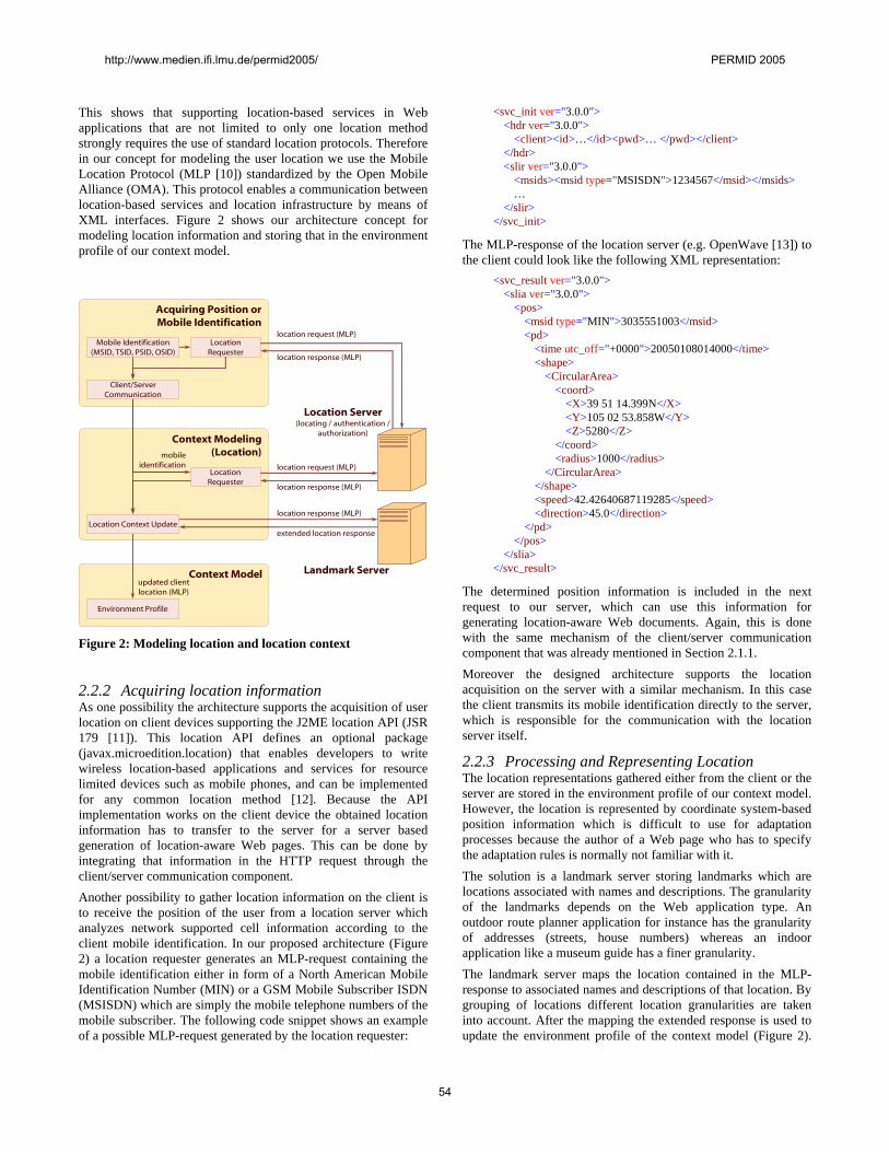
This shows that supporting location-based services in Web applications that are not limited to only one location method strongly requires the use of standard location protocols. Therefore in our concept for modeling the user location we use the Mobile Location Protocol (MLP [10]) standardized by the Open Mobile Alliance (OMA). This protocol enables a communication between location-based services and location infrastructure by means of XML interfaces. Figure 2 shows our architecture concept for modeling location information and storing that in the environment profile of our context model.
Context Model
Acquiring Position orMobile Identification
Environment Profile
Context Modeling(Location)
Location Requester
updated client location (MLP)
Location Server(locating / authentication /
authorization)
Mobile Identification(MSID, TSID, PSID, OSID)
location response (MLP)
Location Context Update
Location Requester
Client/Server Communication
location request (MLP)
location response (MLP)
location request (MLP)
mobile identification
location response (MLP)
extended location response
Landmark Server
Figure 2: Modeling location and location context
2.2.2 Acquiring location information As one possibility the architecture supports the acquisition of user location on client devices supporting the J2ME location API (JSR 179 [11]). This location API defines an optional package (javax.microedition.location) that enables developers to write wireless location-based applications and services for resource limited devices such as mobile phones, and can be implemented for any common location method [12]. Because the API implementation works on the client device the obtained location information has to transfer to the server for a server based generation of location-aware Web pages. This can be done by integrating that information in the HTTP request through the client/server communication component. Another possibility to gather location information on the client is to receive the position of the user from a location server which analyzes network supported cell information according to the client mobile identification. In our proposed architecture (Figure 2) a location requester generates an MLP-request containing the mobile identification either in form of a North American Mobile Identification Number (MIN) or a GSM Mobile Subscriber ISDN (MSISDN) which are simply the mobile telephone numbers of the mobile subscriber. The following code snippet shows an example of a possible MLP-request generated by the location requester:
<svc_init ver="3.0.0"> <hdr ver="3.0.0"> <client><id>…</id><pwd>… </pwd></client> </hdr> <slir ver="3.0.0"> <msids><msid type="MSISDN">1234567</msid></msids> … </slir> </svc_init>
The MLP-response of the location server (e.g. OpenWave [13]) to the client could look like the following XML representation:
<svc_result ver="3.0.0"> <slia ver="3.0.0"> <pos> <msid type="MIN">3035551003</msid> <pd> <time utc_off="+0000">20050108014000</time> <shape> <CircularArea> <coord> <X>39 51 14.399N</X> <Y>105 02 53.858W</Y> <Z>5280</Z> </coord> <radius>1000</radius> </CircularArea> </shape> <speed>42.42640687119285</speed> <direction>45.0</direction> </pd> </pos> </slia> </svc_result>
The determined position information is included in the next request to our server, which can use this information for generating location-aware Web documents. Again, this is done with the same mechanism of the client/server communication component that was already mentioned in Section 2.1.1. Moreover the designed architecture supports the location acquisition on the server with a similar mechanism. In this case the client transmits its mobile identification directly to the server, which is responsible for the communication with the location server itself.
2.2.3 Processing and Representing Location The location representations gathered either from the client or the server are stored in the environment profile of our context model. However, the location is represented by coordinate system-based position information which is difficult to use for adaptation processes because the author of a Web page who has to specify the adaptation rules is normally not familiar with it. The solution is a landmark server storing landmarks which are locations associated with names and descriptions. The granularity of the landmarks depends on the Web application type. An outdoor route planner application for instance has the granularity of addresses (streets, house numbers) whereas an indoor application like a museum guide has a finer granularity. The landmark server maps the location contained in the MLP-response to associated names and descriptions of that location. By grouping of locations different location granularities are taken into account. After the mapping the extended response is used to update the environment profile of the context model (Figure 2).
http://www.medien.ifi.lmu.de/permid2005/ PERMID 2005
54
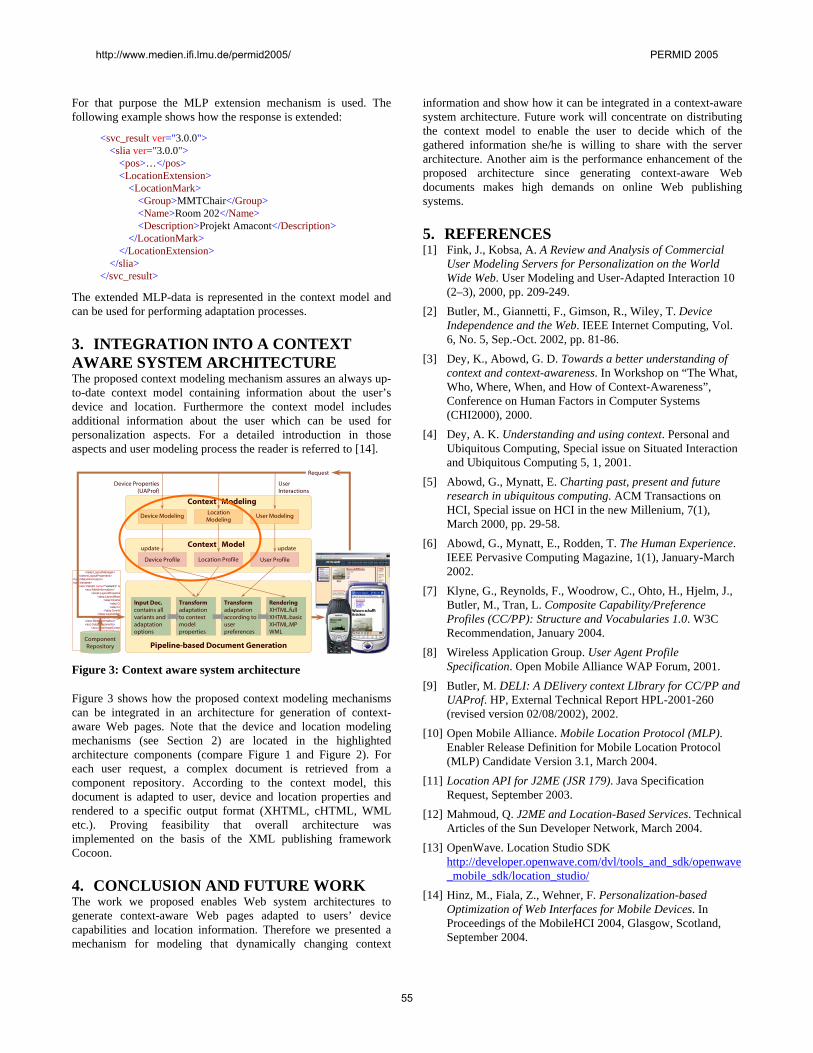
For that purpose the MLP extension mechanism is used. The following example shows how the response is extended:
<svc_result ver="3.0.0"> <slia ver="3.0.0"> <pos>…</pos> <LocationExtension> <LocationMark> <Group>MMTChair</Group> <Name>Room 202</Name> <Description>Projekt Amacont</Description> </LocationMark> </LocationExtension> </slia> </svc_result>
The extended MLP-data is represented in the context model and can be used for performing adaptation processes.
3. INTEGRATION INTO A CONTEXT AWARE SYSTEM ARCHITECTURE The proposed context modeling mechanism assures an always up-to-date context model containing information about the user’s device and location. Furthermore the context model includes additional information about the user which can be used for personalization aspects. For a detailed introduction in those aspects and user modeling process the reader is referred to [14].
Request
Pipeline-based Document Generation
Transformadaptation to context model properties
RenderingXHTML.fullXHTML.basicXHTML.MPWML
Transformadaptation according to user preferences
</alay:LayoutManager> </ amet:LayoutProperties></ aco:MetaInformation><aco:Variants> "va<aco:Variant riant name= 1" la < aco:MetaInformation> <amet:LayoutPropertie <alay:LayoutMana <alay:Overlay <alay:Co <alay:Co </alay:Overla </alay:LayoutMan </amet:LayoutPropertie < /aco:MetaInformation> < aco:SubComponents> <aco:AmaImageCompo <aco:MetaInforma <amet:MetaD <amet:MetaD <b>Ope </amet:MetaD </aco:MetaInforma
ComponentRepository
Input Doc.contains all variants and adaptationoptions
Context Model
Location Profile User ProfileDevice Profile
updateupdate
Context ModelingLocation Modeling
User Interactions
Device Modeling
Device Properties (UAProf)
User Modeling
Figure 3: Context aware system architecture Figure 3 shows how the proposed context modeling mechanisms can be integrated in an architecture for generation of context-aware Web pages. Note that the device and location modeling mechanisms (see Section 2) are located in the highlighted architecture components (compare Figure 1 and Figure 2). For each user request, a complex document is retrieved from a component repository. According to the context model, this document is adapted to user, device and location properties and rendered to a specific output format (XHTML, cHTML, WML etc.). Proving feasibility that overall architecture was implemented on the basis of the XML publishing framework Cocoon.
4. CONCLUSION AND FUTURE WORK The work we proposed enables Web system architectures to generate context-aware Web pages adapted to users’ device capabilities and location information. Therefore we presented a mechanism for modeling that dynamically changing context
information and show how it can be integrated in a context-aware system architecture. Future work will concentrate on distributing the context model to enable the user to decide which of the gathered information she/he is willing to share with the server architecture. Another aim is the performance enhancement of the proposed architecture since generating context-aware Web documents makes high demands on online Web publishing systems.
5. REFERENCES [1] Fink, J., Kobsa, A. A Review and Analysis of Commercial
User Modeling Servers for Personalization on the World Wide Web. User Modeling and User-Adapted Interaction 10 (2–3), 2000, pp. 209-249.
[2] Butler, M., Giannetti, F., Gimson, R., Wiley, T. Device Independence and the Web. IEEE Internet Computing, Vol. 6, No. 5, Sep.-Oct. 2002, pp. 81-86.
[3] Dey, K., Abowd, G. D. Towards a better understanding of context and context-awareness. In Workshop on “The What, Who, Where, When, and How of Context-Awareness”, Conference on Human Factors in Computer Systems (CHI2000), 2000.
[4] Dey, A. K. Understanding and using context. Personal and Ubiquitous Computing, Special issue on Situated Interaction and Ubiquitous Computing 5, 1, 2001.
[5] Abowd, G., Mynatt, E. Charting past, present and future research in ubiquitous computing. ACM Transactions on HCI, Special issue on HCI in the new Millenium, 7(1), March 2000, pp. 29-58.
[6] Abowd, G., Mynatt, E., Rodden, T. The Human Experience. IEEE Pervasive Computing Magazine, 1(1), January-March 2002.
[7] Klyne, G., Reynolds, F., Woodrow, C., Ohto, H., Hjelm, J., Butler, M., Tran, L. Composite Capability/Preference Profiles (CC/PP): Structure and Vocabularies 1.0. W3C Recommendation, January 2004.
[8] Wireless Application Group. User Agent Profile Specification. Open Mobile Alliance WAP Forum, 2001.
[9] Butler, M. DELI: A DElivery context LIbrary for CC/PP and UAProf. HP, External Technical Report HPL-2001-260 (revised version 02/08/2002), 2002.
[10] Open Mobile Alliance. Mobile Location Protocol (MLP). Enabler Release Definition for Mobile Location Protocol (MLP) Candidate Version 3.1, March 2004.
[11] Location API for J2ME (JSR 179). Java Specification Request, September 2003.
[12] Mahmoud, Q. J2ME and Location-Based Services. Technical Articles of the Sun Developer Network, March 2004.
[13] OpenWave. Location Studio SDK http://developer.openwave.com/dvl/tools_and_sdk/openwave_mobile_sdk/location_studio/
[14] Hinz, M., Fiala, Z., Wehner, F. Personalization-based Optimization of Web Interfaces for Mobile Devices. In Proceedings of the MobileHCI 2004, Glasgow, Scotland, September 2004.
http://www.medien.ifi.lmu.de/permid2005/ PERMID 2005
55
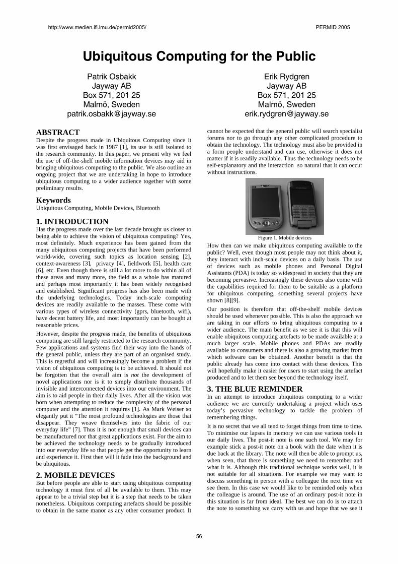
Ubiquitous Computing for the PublicPatrik Osbakk
Jayway AB Box 571, 201 25 Malmö, Sweden
Erik Rydgren Jayway AB
Box 571, 201 25 Malmö, Sweden
ABSTRACT Despite the progress made in Ubiquitous Computing since it was first envisaged back in 1987 [1], its use is still isolated to the research community. In this paper, we present why we feel the use of off-the-shelf mobile information devices may aid in bringing ubiquitous computing to the public. We also outline an ongoing project that we are undertaking in hope to introduce ubiquitous computing to a wider audience together with some preliminary results.
Keywords Ubiquitous Computing, Mobile Devices, Bluetooth
1. INTRODUCTION Has the progress made over the last decade brought us closer to being able to achieve the vision of ubiquitous computing? Yes, most definitely. Much experience has been gained from the many ubiquitous computing projects that have been performed world-wide, covering such topics as location sensing [2], context-awareness [3], privacy [4], fieldwork [5], health care [6], etc. Even though there is still a lot more to do within all of these areas and many more, the field as a whole has matured and perhaps most importantly it has been widely recognised and established. Significant progress has also been made with the underlying technologies. Today inch-scale computing devices are readily available to the masses. These come with various types of wireless connectivity (gprs, bluetooth, wifi), have decent battery life, and most importantly can be bought at reasonable prices. However, despite the progress made, the benefits of ubiquitous computing are still largely restricted to the research community. Few applications and systems find their way into the hands of the general public, unless they are part of an organised study. This is regretful and will increasingly become a problem if the vision of ubiquitous computing is to be achieved. It should not be forgotten that the overall aim is not the development of novel applications nor is it to simply distribute thousands of invisible and interconnected devices into our environment. The aim is to aid people in their daily lives. After all the vision was born when attempting to reduce the complexity of the personal computer and the attention it requires [1]. As Mark Weiser so elegantly put it “The most profound technologies are those that disappear. They weave themselves into the fabric of our everyday life” [7]. Thus it is not enough that small devices can be manufactured nor that great applications exist. For the aim to be achieved the technology needs to be gradually introduced into our everyday life so that people get the opportunity to learn and experience it. First then will it fade into the background and be ubiquitous.
2. MOBILE DEVICES But before people are able to start using ubiquitous computing technology it must first of all be available to them. This may appear to be a trivial step but it is a step that needs to be taken nonetheless. Ubiquitous computing artefacts should be possible to obtain in the same manor as any other consumer product. It
cannot be expected that the general public will search specialist forums nor to go through any other complicated procedure to obtain the technology. The technology must also be provided in a form people understand and can use, otherwise it does not matter if it is readily available. Thus the technology needs to be self-explanatory and the interaction so natural that it can occur without instructions.
Figure 1. Mobile devices
How then can we make ubiquitous computing available to the public? Well, even though most people may not think about it, they interact with inch-scale devices on a daily basis. The use of devices such as mobile phones and Personal Digital Assistants (PDA) is today so widespread in society that they are becoming pervasive. Increasingly these devices also come with the capabilities required for them to be suitable as a platform for ubiquitous computing, something several projects have shown [8][9]. Our position is therefore that off-the-shelf mobile devices should be used whenever possible. This is also the approach we are taking in our efforts to bring ubiquitous computing to a wider audience. The main benefit as we see it is that this will enable ubiquitous computing artefacts to be made available at a much larger scale. Mobile phones and PDAs are readily available to consumers and there is also a growing market from which software can be obtained. Another benefit is that the public already has come into contact with these devices. This will hopefully make it easier for users to start using the artefact produced and to let them see beyond the technology itself.
3. THE BLUE REMINDER In an attempt to introduce ubiquitous computing to a wider audience we are currently undertaking a project which uses today’s pervasive technology to tackle the problem of remembering things. It is no secret that we all tend to forget things from time to time. To minimise our lapses in memory we can use various tools in our daily lives. The post-it note is one such tool. We may for example stick a post-it note on a book with the date when it is due back at the library. The note will then be able to prompt us, when seen, that there is something we need to remember and what it is. Although this traditional technique works well, it is not suitable for all situations. For example we may want to discuss something in person with a colleague the next time we see them. In this case we would like to be reminded only when the colleague is around. The use of an ordinary post-it note in this situation is far from ideal. The best we can do is to attach the note to something we carry with us and hope that we see it
http://www.medien.ifi.lmu.de/permid2005/ PERMID 2005
56
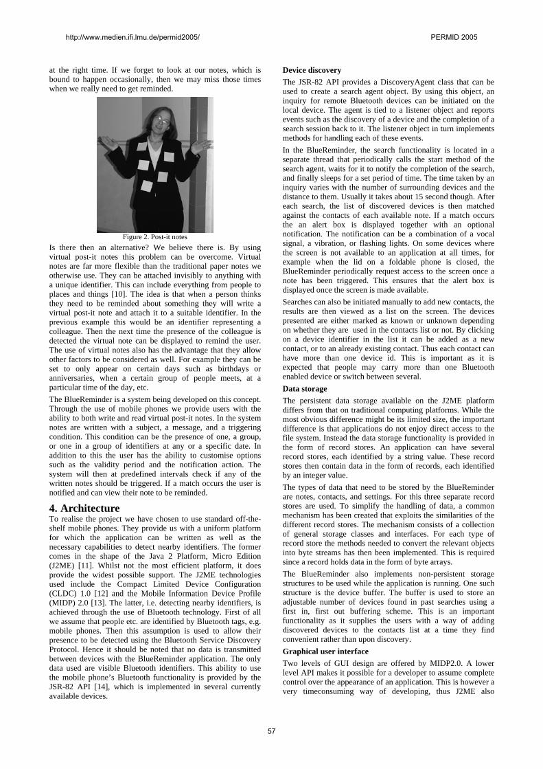
at the right time. If we forget to look at our notes, which is bound to happen occasionally, then we may miss those times when we really need to get reminded.
Figure 2. Post-it notes
Is there then an alternative? We believe there is. By using virtual post-it notes this problem can be overcome. Virtual notes are far more flexible than the traditional paper notes we otherwise use. They can be attached invisibly to anything with a unique identifier. This can include everything from people to places and things [10]. The idea is that when a person thinks they need to be reminded about something they will write a virtual post-it note and attach it to a suitable identifier. In the previous example this would be an identifier representing a colleague. Then the next time the presence of the colleague is detected the virtual note can be displayed to remind the user. The use of virtual notes also has the advantage that they allow other factors to be considered as well. For example they can be set to only appear on certain days such as birthdays or anniversaries, when a certain group of people meets, at a particular time of the day, etc. The BlueReminder is a system being developed on this concept. Through the use of mobile phones we provide users with the ability to both write and read virtual post-it notes. In the system notes are written with a subject, a message, and a triggering condition. This condition can be the presence of one, a group, or one in a group of identifiers at any or a specific date. In addition to this the user has the ability to customise options such as the validity period and the notification action. The system will then at predefined intervals check if any of the written notes should be triggered. If a match occurs the user is notified and can view their note to be reminded.
4. Architecture To realise the project we have chosen to use standard off-the-shelf mobile phones. They provide us with a uniform platform for which the application can be written as well as the necessary capabilities to detect nearby identifiers. The former comes in the shape of the Java 2 Platform, Micro Edition (J2ME) [11]. Whilst not the most efficient platform, it does provide the widest possible support. The J2ME technologies used include the Compact Limited Device Configuration (CLDC) 1.0 [12] and the Mobile Information Device Profile (MIDP) 2.0 [13]. The latter, i.e. detecting nearby identifiers, is achieved through the use of Bluetooth technology. First of all we assume that people etc. are identified by Bluetooth tags, e.g. mobile phones. Then this assumption is used to allow their presence to be detected using the Bluetooth Service Discovery Protocol. Hence it should be noted that no data is transmitted between devices with the BlueReminder application. The only data used are visible Bluetooth identifiers. This ability to use the mobile phone’s Bluetooth functionality is provided by the JSR-82 API [14], which is implemented in several currently available devices.
Device discovery The JSR-82 API provides a DiscoveryAgent class that can be used to create a search agent object. By using this object, an inquiry for remote Bluetooth devices can be initiated on the local device. The agent is tied to a listener object and reports events such as the discovery of a device and the completion of a search session back to it. The listener object in turn implements methods for handling each of these events. In the BlueReminder, the search functionality is located in a separate thread that periodically calls the start method of the search agent, waits for it to notify the completion of the search, and finally sleeps for a set period of time. The time taken by an inquiry varies with the number of surrounding devices and the distance to them. Usually it takes about 15 second though. After each search, the list of discovered devices is then matched against the contacts of each available note. If a match occurs the an alert box is displayed together with an optional notification. The notification can be a combination of a vocal signal, a vibration, or flashing lights. On some devices where the screen is not available to an application at all times, for example when the lid on a foldable phone is closed, the BlueReminder periodically request access to the screen once a note has been triggered. This ensures that the alert box is displayed once the screen is made available. Searches can also be initiated manually to add new contacts, the results are then viewed as a list on the screen. The devices presented are either marked as known or unknown depending on whether they are used in the contacts list or not. By clicking on a device identifier in the list it can be added as a new contact, or to an already existing contact. Thus each contact can have more than one device id. This is important as it is expected that people may carry more than one Bluetooth enabled device or switch between several. Data storage The persistent data storage available on the J2ME platform differs from that on traditional computing platforms. While the most obvious difference might be its limited size, the important difference is that applications do not enjoy direct access to the file system. Instead the data storage functionality is provided in the form of record stores. An application can have several record stores, each identified by a string value. These record stores then contain data in the form of records, each identified by an integer value. The types of data that need to be stored by the BlueReminder are notes, contacts, and settings. For this three separate record stores are used. To simplify the handling of data, a common mechanism has been created that exploits the similarities of the different record stores. The mechanism consists of a collection of general storage classes and interfaces. For each type of record store the methods needed to convert the relevant objects into byte streams has then been implemented. This is required since a record holds data in the form of byte arrays. The BlueReminder also implements non-persistent storage structures to be used while the application is running. One such structure is the device buffer. The buffer is used to store an adjustable number of devices found in past searches using a first in, first out buffering scheme. This is an important functionality as it supplies the users with a way of adding discovered devices to the contacts list at a time they find convenient rather than upon discovery. Graphical user interface Two levels of GUI design are offered by MIDP2.0. A lower level API makes it possible for a developer to assume complete control over the appearance of an application. This is however a very timeconsuming way of developing, thus J2ME also
http://www.medien.ifi.lmu.de/permid2005/ PERMID 2005
57
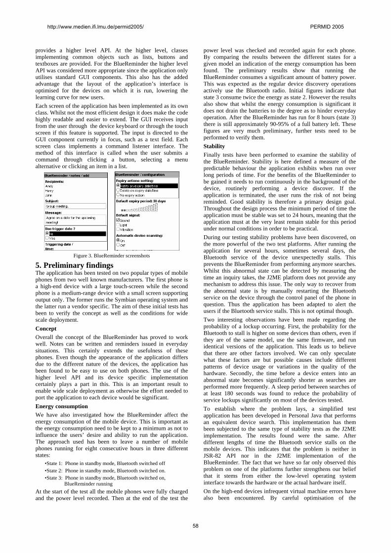
provides a higher level API. At the higher level, classes implementing common objects such as lists, buttons and textboxes are provided. For the BlueReminder the higher level API was considered more appropriate since the application only utilises standard GUI components. This also has the added advantage that the layout of the application’s interface is optimised for the devices on which it is run, lowering the learning curve for new users. Each screen of the application has been implemented as its own class. Whilst not the most efficient design it does make the code highly readable and easier to extend. The GUI receives input from the user through the device keyboard or through the touch screen if this feature is supported. The input is directed to the GUI component currently in focus, such as a text field. Each screen class implements a command listener interface. The method of this interface is called when the user submits a command through clicking a button, selecting a menu alternative or clicking an item in a list.
Figure 3. BlueReminder screenshots
5. Preliminary findings The application has been tested on two popular types of mobile phones from two well known manufacturers. The first phone is a high-end device with a large touch-screen while the second phone is a medium-range device with a small screen supporting output only. The former runs the Symbian operating system and the latter run a vendor specific. The aim of these initial tests has been to verify the concept as well as the conditions for wide scale deployment. Concept Overall the concept of the BlueReminder has proved to work well. Notes can be written and reminders issued in everyday situations. This certainly extends the usefulness of these phones. Even though the appearance of the application differs due to the different nature of the devices, the application has been found to be easy to use on both phones. The use of the higher level API and its device specific implementation certainly plays a part in this. This is an important result to enable wide scale deployment as otherwise the effort needed to port the application to each device would be significant. Energy consumption We have also investigated how the BlueReminder affect the energy consumption of the mobile device. This is important as the energy consumption need to be kept to a minimum as not to influence the users’ desire and ability to run the application. The approach used has been to leave a number of mobile phones running for eight consecutive hours in three different states:
•State 1: Phone in standby mode, Bluetooth switched off •State 2: Phone in standby mode, Bluetooth switched on. •State 3: Phone in standby mode, Bluetooth switched on, BlueReminder running
At the start of the test all the mobile phones were fully charged and the power level recorded. Then at the end of the test the
power level was checked and recorded again for each phone. By comparing the results between the different states for a given model an indication of the energy consumption has been found. The preliminary results show that running the BlueReminder consumes a significant amount of battery power. This was expected as the regular device discovery operations actively use the Bluetooth radio. Initial figures indicate that state 3 consume twice the energy as state 2. However the results also show that whilst the energy consumption is significant it does not drain the batteries to the degree as to hinder everyday operation. After the BlueReminder has run for 8 hours (state 3) there is still approximately 90-95% of a full battery left. These figures are very much preliminary, further tests need to be performed to verify them. Stability Finally tests have been performed to examine the stability of the BlueReminder. Stability is here defined a measure of the predictable behaviour the application exhibits when run over long periods of time. For the benefits of the BlueReminder to be gained it needs to run continuously in the background of the device, routinely performing a device discover. If the application is terminated, the user runs the risk of not being reminded. Good stability is therefore a primary design goal. Throughout the design process the minimum period of time the application must be stable was set to 24 hours, meaning that the application must at the very least remain stable for this period under normal conditions in order to be practical. During our testing stability problems have been discovered, on the more powerful of the two test platforms. After running the application for several hours, sometimes several days, the Bluetooth service of the device unexpectedly stalls. This prevents the BlueReminder from performing anymore searches. Whilst this abnormal state can be detected by measuring the time an inquiry takes, the J2ME platform does not provide any mechanism to address this issue. The only way to recover from the abnormal state is by manually restarting the Bluetooth service on the device through the control panel of the phone in question. Thus the application has been adapted to alert the users if the Bluetooth service stalls. This is not optimal though. Two interesting observations have been made regarding the probability of a lockup occurring. First, the probability for the Bluetooth to stall is higher on some devices than others, even if they are of the same model, use the same firmware, and run identical versions of the application. This leads us to believe that there are other factors involved. We can only speculate what these factors are but possible causes include different patterns of device usage or variations in the quality of the hardware. Secondly, the time before a device enters into an abnormal state becomes significantly shorter as searches are performed more frequently. A sleep period between searches of at least 180 seconds was found to reduce the probability of service lockups significantly on most of the devices tested. To establish where the problem lays, a simplified test application has been developed in Personal Java that performs an equivalent device search. This implementation has them been subjected to the same type of stability tests as the J2ME implementation. The results found were the same. After different lengths of time the Bluetooth service stalls on the mobile devices. This indicates that the problem is neither in JSR-82 API nor in the J2ME implementation of the BlueReminder. The fact that we have so far only observed this problem on one of the platforms further strengthens our belief that it stems from either the low-level operating system interface towards the hardware or the actual hardware itself. On the high-end devices infrequent virtual machine errors have also been encountered. By careful optimisation of the
http://www.medien.ifi.lmu.de/permid2005/ PERMID 2005
58
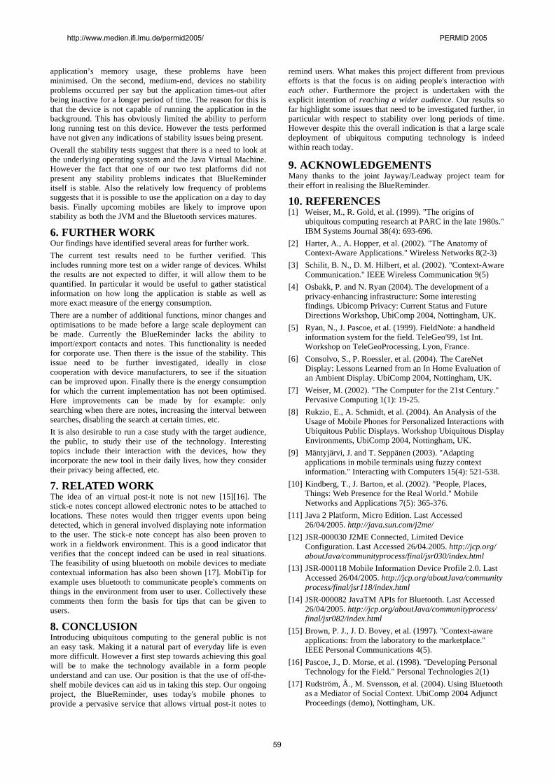
application’s memory usage, these problems have been minimised. On the second, medium-end, devices no stability problems occurred per say but the application times-out after being inactive for a longer period of time. The reason for this is that the device is not capable of running the application in the background. This has obviously limited the ability to perform long running test on this device. However the tests performed have not given any indications of stability issues being present. Overall the stability tests suggest that there is a need to look at the underlying operating system and the Java Virtual Machine. However the fact that one of our two test platforms did not present any stability problems indicates that BlueReminder itself is stable. Also the relatively low frequency of problems suggests that it is possible to use the application on a day to day basis. Finally upcoming mobiles are likely to improve upon stability as both the JVM and the Bluetooth services matures.
6. FURTHER WORK Our findings have identified several areas for further work. The current test results need to be further verified. This includes running more test on a wider range of devices. Whilst the results are not expected to differ, it will allow them to be quantified. In particular it would be useful to gather statistical information on how long the application is stable as well as more exact measure of the energy consumption. There are a number of additional functions, minor changes and optimisations to be made before a large scale deployment can be made. Currently the BlueReminder lacks the ability to import/export contacts and notes. This functionality is needed for corporate use. Then there is the issue of the stability. This issue need to be further investigated, ideally in close cooperation with device manufacturers, to see if the situation can be improved upon. Finally there is the energy consumption for which the current implementation has not been optimised. Here improvements can be made by for example: only searching when there are notes, increasing the interval between searches, disabling the search at certain times, etc. It is also desirable to run a case study with the target audience, the public, to study their use of the technology. Interesting topics include their interaction with the devices, how they incorporate the new tool in their daily lives, how they consider their privacy being affected, etc.
7. RELATED WORK The idea of an virtual post-it note is not new [15][16]. The stick-e notes concept allowed electronic notes to be attached to locations. These notes would then trigger events upon being detected, which in general involved displaying note information to the user. The stick-e note concept has also been proven to work in a fieldwork environment. This is a good indicator that verifies that the concept indeed can be used in real situations. The feasibility of using bluetooth on mobile devices to mediate contextual information has also been shown [17]. MobiTip for example uses bluetooth to communicate people's comments on things in the environment from user to user. Collectively these comments then form the basis for tips that can be given to users.
8. CONCLUSION Introducing ubiquitous computing to the general public is not an easy task. Making it a natural part of everyday life is even more difficult. However a first step towards achieving this goal will be to make the technology available in a form people understand and can use. Our position is that the use of off-the-shelf mobile devices can aid us in taking this step. Our ongoing project, the BlueReminder, uses today's mobile phones to provide a pervasive service that allows virtual post-it notes to
remind users. What makes this project different from previous efforts is that the focus is on aiding people's interaction with each other. Furthermore the project is undertaken with the explicit intention of reaching a wider audience. Our results so far highlight some issues that need to be investigated further, in particular with respect to stability over long periods of time. However despite this the overall indication is that a large scale deployment of ubiquitous computing technology is indeed within reach today.
9. ACKNOWLEDGEMENTS Many thanks to the joint Jayway/Leadway project team for their effort in realising the BlueReminder.
10. REFERENCES [1] Weiser, M., R. Gold, et al. (1999). "The origins of
ubiquitous computing research at PARC in the late 1980s." IBM Systems Journal 38(4): 693-696.
[2] Harter, A., A. Hopper, et al. (2002). "The Anatomy of Context-Aware Applications." Wireless Networks 8(2-3)
[3] Schilit, B. N., D. M. Hilbert, et al. (2002). "Context-Aware Communication." IEEE Wireless Communication 9(5)
[4] Osbakk, P. and N. Ryan (2004). The development of a privacy-enhancing infrastructure: Some interesting findings. Ubicomp Privacy: Current Status and Future Directions Workshop, UbiComp 2004, Nottingham, UK.
[5] Ryan, N., J. Pascoe, et al. (1999). FieldNote: a handheld information system for the field. TeleGeo'99, 1st Int. Workshop on TeleGeoProcessing, Lyon, France.
[6] Consolvo, S., P. Roessler, et al. (2004). The CareNet Display: Lessons Learned from an In Home Evaluation of an Ambient Display. UbiComp 2004, Nottingham, UK.
[7] Weiser, M. (2002). "The Computer for the 21st Century." Pervasive Computing 1(1): 19-25.
[8] Rukzio, E., A. Schmidt, et al. (2004). An Analysis of the Usage of Mobile Phones for Personalized Interactions with Ubiquitous Public Displays. Workshop Ubiquitous Display Environments, UbiComp 2004, Nottingham, UK.
[9] Mäntyjärvi, J. and T. Seppänen (2003). "Adapting applications in mobile terminals using fuzzy context information." Interacting with Computers 15(4): 521-538.
[10] Kindberg, T., J. Barton, et al. (2002). "People, Places, Things: Web Presence for the Real World." Mobile Networks and Applications 7(5): 365-376.
[11] Java 2 Platform, Micro Edition. Last Accessed 26/04/2005. http://java.sun.com/j2me/
[12] JSR-000030 J2ME Connected, Limited Device Configuration. Last Accessed 26/04.2005. http://jcp.org/ aboutJava/communityprocess/final/jsr030/index.html
[13] JSR-000118 Mobile Information Device Profile 2.0. Last Accessed 26/04/2005. http://jcp.org/aboutJava/community process/final/jsr118/index.html
[14] JSR-000082 JavaTM APIs for Bluetooth. Last Accessed 26/04/2005. http://jcp.org/aboutJava/communityprocess/ final/jsr082/index.html
[15] Brown, P. J., J. D. Bovey, et al. (1997). "Context-aware applications: from the laboratory to the marketplace." IEEE Personal Communications 4(5).
[16] Pascoe, J., D. Morse, et al. (1998). "Developing Personal Technology for the Field." Personal Technologies 2(1)
[17] Rudström, Å., M. Svensson, et al. (2004). Using Bluetooth as a Mediator of Social Context. UbiComp 2004 Adjunct Proceedings (demo), Nottingham, UK.
http://www.medien.ifi.lmu.de/permid2005/ PERMID 2005
59