Embed Size (px)
Citation preview

f
gb
i
e
d
PhRf / chgf
Pompe à chaleur et groupe d’eau glacée 20 à 85 kW - air / eauÉquipement hydraulique complet intégré - Fluide réfrigérant R 410 A
heat pump and chiller 20 to 85 kW - air to watercomplete built-in hydraulic equipment - R 410 A refrigerant
Pompa di calore e refrigeratore d'acqua 20 a 85 kW - aria / acquasezione idronica completa integrata - Fluido refrigerante R 410 A
bomba de calor y grupo de agua fría 20 a 85 kW - aire / aguaequipo hidráulico completo integrado - Fluido refrigerante R 410 A
Wärmepumpe und Kaltwassersatz luft- / wassergekühlt - 20 bis 85 kWMit eingebauter kompletter hydraulikausstattung - Kältemittel R 410 A
Février 2013 10 11 588 - F.GB.I.E.D - 01
Notice d’iNstaLLatioN
iNstaLLatioN iNstRUctioN
MaNUaLe d’iNstaLLaZioNe
MaNUaL de iNstaLacióN
aUfsteLLUNgs-haNdbUch
(Etiquette signalétique)
GB
2
SuMMARY
1 - Generalities . . . . . . . . . . . . . . . . . . . . . . . . . . . . . . . . . . . . . . . . . .32 - Description of components . . . . . . . . . . . . . . . . . . . . . . . . . . . . . .43 - Hydraulic circuit diagram . . . . . . . . . . . . . . . . . . . . . . . . . . . . . . . .74 - Overall dimensions . . . . . . . . . . . . . . . . . . . . . . . . . . . . . . . . . . . .85 - Space required for installation . . . . . . . . . . . . . . . . . . . . . . . . . . . .96 - Hydraulic connections . . . . . . . . . . . . . . . . . . . . . . . . . . . . . . . . .117 - Electrical connections . . . . . . . . . . . . . . . . . . . . . . . . . . . . . . . . .128 - Starting . . . . . . . . . . . . . . . . . . . . . . . . . . . . . . . . . . . . . . . . . . . . .159 - µC2SE electronic control . . . . . . . . . . . . . . . . . . . . . . . . . . . . . . .19
10 - Operating limits . . . . . . . . . . . . . . . . . . . . . . . . . . . . . . . . . . . . . .3011 - Control and safety devices . . . . . . . . . . . . . . . . . . . . . . . . . . . . .3112 - Maintenance instructions . . . . . . . . . . . . . . . . . . . . . . . . . . . . . . .3213 - Recycling . . . . . . . . . . . . . . . . . . . . . . . . . . . . . . . . . . . . . . . . . . .3214 - Technical characteristics . . . . . . . . . . . . . . . . . . . . . . . . . . . . . . .3315 - Cooling diagrams . . . . . . . . . . . . . . . . . . . . . . . . . . . . . . . . . . . . .3516 - Troubleshooting . . . . . . . . . . . . . . . . . . . . . . . . . . . . . . . . . . . . . .3817 - Start-up data sheet . . . . . . . . . . . . . . . . . . . . . . . . . . . . . . . . . . .42
MARKING
This product marked conforms to the essential requirements of the Directives:
- Low voltage no. 2006/95/EC.
- Electromagnetic Compatibility no. 2004/108/EC.
NOTE: This symbol mark and recycle system are applied only to EU countries and not applied to the countries in theother area of the world.
Your product is designed and manufactured with high quality materials and components which can be recycled and reused.This symbol means that electrical and electronic equipment, at their end-of-life, should be disposed separately from yourhousehold waste.Please dispose of this equipment at your local community waste collection / recycling centre.In the European Union there are separate collection systems for used electrical and electronic products.Please help us to conserve the environment we live in!
R 410 A
• R 410 A is a high-pressure refrigerant (+ 50% in relation to R 22 and R 407 C).
• The compressors approved for operation with this fluid arefilled beforehand with polyvinyl ether oil.
MAINTENANCE INSTRuCTIoNS
1 - Never add oil to the appliance; the compressor is filledwith polyvinyl ether (PVE) oil, a special oil which cannottolerate the presence of other oils.
2 - The instruments used for:- Filling,- Pressure measurements,- Emptying under vacuum,- Recovering the fluid,
must be compatible and only used for the R 410 A fluid.Note: the pressure taps of the refrigerating circuit are5/16 SAE (1/2 - 20 - UNF).
3 - In the case of a new charge:- The charge must be undertaken in liquid phase.- Use a balance and a dip pipe type R 410 A cylinder.
- Charge the weight of R 410 A as per the value indicatedon the unit’s identification plate.
4 - In case of leakage, do not complete the charge: recoverthe remaining refrigerant for recycling and perform a totalcharge.
Recovery, recycling or the destruction of the fluid must bedone in compliance with the laws in force in the countryconcerned.
5 - If the refrigerant circuit is opened, you must:- Avoid ambient air from entering the circuit.- Replace or install a drier.- Perform the “vacuum operation” at a minimum level of
0.3 mbar (static).
6 - Do not release R 410 A fluid into the atmosphere. Thisfluid is a fluorinated greenhouse gases, covered by theKyoto Protocol with a Global Warming Potential(GWP) = 1975 - (CE Directive 842 / 2006).
APPLIANCES FILLED WITH R 410 A
GB
3
1 - GENERALITIES
1.1 - GENERAL SuPPLY CoNDITIoNS• Generally speaking, the material is transported at the consignee’s risk.
• The consignee must immediately provide the carrier with written reserves if he finds any damage caused during transport.
1.2 - RECoMMENDATIoNS• Prior to all servicing or other actions on the equipment, installation, commissioning, operation, or maintenance, the
personnel in charge of these operations shall become familiar with the instructions and recommendations provided in theinstallation manual of the unit as well as the elements of the project's technical file.
• The personnel responsible for receiving the unit must conduct a visual inspection in order to identify all damage to whichthe unit may have been subjected during transport: refrigerating circuit, electrical cabinet, chassis and cabinet.
• The unit must be installed, started, maintained, serviced by qualified and authorised personnel, in compliance with therequirements of all directives, laws and regulations and in accordance with standard trade practices.
• During installation, troubleshooting and maintenance operations, the use of pipes as a step: under the stress, the pipe mayrupture and the refrigerant may cause serious burns.
1.3 - VoLTAGE• Before carrying out any operation, check that the voltage indicated on the unit corresponds to the mains voltage.
• Before initiating maintenance or servicing on the installation, check that its power supply is disconnected and locked out.
1.4 - uSE oF EQuIPMENT• This device is designed for heating buildings.
This appliance is not designed to be used by people (including children) whose physical, sensory or mentalcapacities are impaired, or who lack experience or knowledge, unless they are supervised or have receivedinstructions on how to use the appliance by a person who is responsible for their safety. Children must besupervised to ensure that they do not play with the appliance or its accessories.
1.5 - oPERATING CoNDITIoNS• See the technical characteristics, nominal conditions and operating limits in the 10 12 203 technical instructions, particularly
to ensure the correct selection of appliance.
IMPoRTANT

GB
4
2 - DESCRIPTIoN oF CoMPoNENTS
2.1 - CHGF 20-24 / PHRF 23-27
2
1
5
4 7
5
18
11
8
6
12
15 17
9
14
16
13
3
10
1 - R 410 A air source heat exchanger.
2 - R 410 A water source heat exchanger.
3 - Axial fans.
4 - Water differential pressure switch.
5 - Automatic air bleeder valve.
6 - Expansion vessel.
7 - Buffer tank.
8 - Fill point.
9 - 4-way valve (PHRF).
10 - Pressure reducers.
11 - Safety valve.
12 - Liquid recovery device.
13 - Circulation pump.
14 - Compressor.
15 - Filter dryer.
16 - Low pressure switch and pressure tap.
17 - High pressure switch and pressure tap.
18 - Water pressure gauge.
GB
5
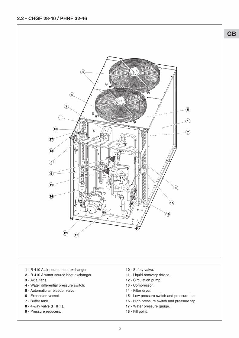
2.2 - CHGF 28-40 / PHRF 32-46
17
10
1
2
4
3
18
5
11
14
12 13
6
7
1
15
8
16
9
1 - R 410 A air source heat exchanger.
2 - R 410 A water source heat exchanger.
3 - Axial fans.
4 - Water differential pressure switch.
5 - Automatic air bleeder valve.
6 - Expansion vessel.
7 - Buffer tank.
8 - 4-way valve (PHRF).
9 - Pressure reducers.
10 - Safety valve.
11 - Liquid recovery device.
12 - Circulation pump.
13 - Compressor.
14 - Filter dryer.
15 - Low pressure switch and pressure tap.
16 - High pressure switch and pressure tap.
17 - Water pressure gauge.
18 - Fill point.

GB
6
2.3 - CHGF 55-76 / PHRF 60-85
253
17 1
156
416
87
910
1418
11
1213
1 - R 410 A air source heat exchanger.
2 - R 410 A water source heat exchanger.
3 - Fans.
4 - Water differential pressure switch.
5 - Automatic air bleeder valve.
6 - Expansion vessel.
7 - Buffer tank.
8 - 4-way valve (PHRF).
9 - Pressure reducers.
10 - Safety valve.
11 - Liquid recovery device.
12 - Circulation pump.
13 - Compressor.
14 - Filter dryer.
15 - Low pressure switch and pressure tap.
16 - High pressure switch and pressure tap.
17 - Water pressure gauge.
18 - Fill point.

GB
7
3 - HYDRAuLIC CIRCuIT DIAGRAM
EVAPoRAToR, PuMP AND TANK
Legend:
VS Safety valve.
EV Evaporator.
PD Differential pressure switch.
MA Water pressure gauge.
VAS Air bleeder valve.
VE Expansion vessel.
MA
VASVS
EVRC
PD
P
VU
VU
P
VAS
VE
RS
P Pump.
RS Drain valve.
RC Water charge valve.
Vu Unidirectional valve.
Inlet
outlet
As option
As option
GB
8
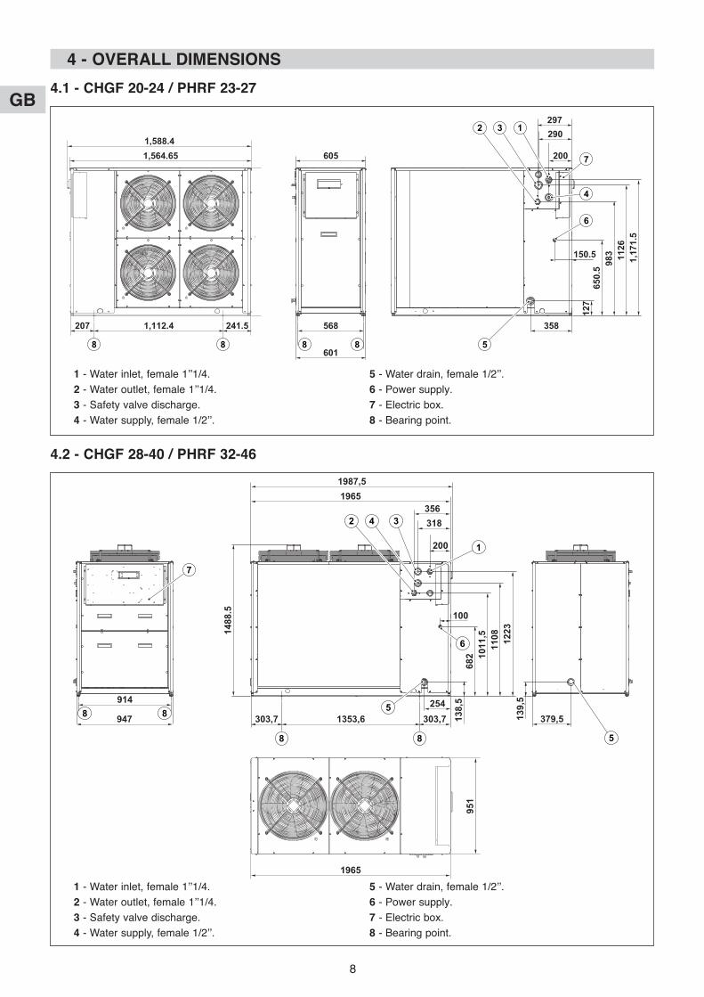
4 - oVERALL DIMENSIoNS
4.1 - CHGF 20-24 / PHRF 23-27
1,564.65 605 200
150.5
290297
1,112.4 241.5207
1,588.4
5
6
7
132
4
8 8 8 8
568 358
127
650.5 98
3 1126
1,171.5
601
1 - Water inlet, female 1’’1/4.
2 - Water outlet, female 1’’1/4.
3 - Safety valve discharge.
4 - Water supply, female 1/2’’.
5 - Water drain, female 1/2’’.
6 - Power supply.
7 - Electric box.
8 - Bearing point.
4.2 - CHGF 28-40 / PHRF 32-46
379,5
100
200
318356
1965
1965
1987,5
1353,6 303,7254
303,7
1
6
342
7
5
5
8 8
947
9148 8 13
9,5
138,5
682 1011,5
1108 1223
951
1488.5
1 - Water inlet, female 1’’1/4.
2 - Water outlet, female 1’’1/4.
3 - Safety valve discharge.
4 - Water supply, female 1/2’’.
5 - Water drain, female 1/2’’.
6 - Power supply.
7 - Electric box.
8 - Bearing point.
GB
9
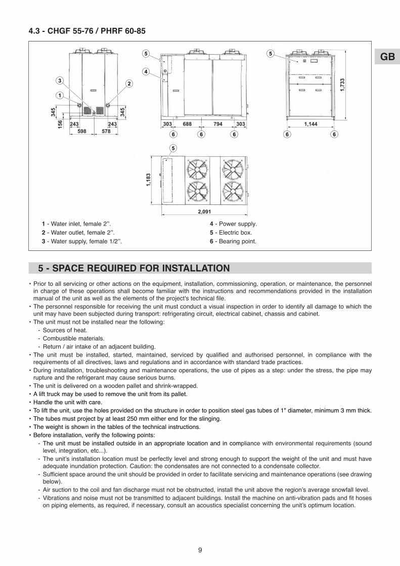
4.3 - CHGF 55-76 / PHRF 60-85
2,091
6 6 6 6 6
1
4
5 5
3 2
5
243 243598 578
303 688 1,144794 303156345
345
1,183
1,733
1 - Water inlet, female 2’’.
2 - Water outlet, female 2’’.
3 - Water supply, female 1/2’’.
4 - Power supply.
5 - Electric box.
6 - Bearing point.
5 - SPACE REQuIRED FoR INSTALLATIoN
• Prior to all servicing or other actions on the equipment, installation, commissioning, operation, or maintenance, the personnelin charge of these operations shall become familiar with the instructions and recommendations provided in the installationmanual of the unit as well as the elements of the project's technical file.
• The personnel responsible for receiving the unit must conduct a visual inspection in order to identify all damage to which theunit may have been subjected during transport: refrigerating circuit, electrical cabinet, chassis and cabinet.
• The unit must not be installed near the following:
- Sources of heat.
- Combustible materials.
- Return / air intake of an adjacent building.
• The unit must be installed, started, maintained, serviced by qualified and authorised personnel, in compliance with therequirements of all directives, laws and regulations and in accordance with standard trade practices.
• During installation, troubleshooting and maintenance operations, the use of pipes as a step: under the stress, the pipe mayrupture and the refrigerant may cause serious burns.
• The unit is delivered on a wooden pallet and shrink-wrapped.
• A lift truck may be used to remove the unit from its pallet.
• Handle the unit with care.
• To lift the unit, use the holes provided on the structure in order to position steel gas tubes of 1" diameter, minimum 3 mm thick.
• The tubes must project by at least 250 mm either end for the slinging.
• The weight is shown in the tables of the technical instructions.
• Before installation, verify the following points:
- The unit must be installed outside in an appropriate location and in compliance with environmental requirements (soundlevel, integration, etc...).
- The unit’s installation location must be perfectly level and strong enough to support the weight of the unit and must haveadequate inundation protection. Caution: the condensates are not connected to a condensate collector.
- Sufficient space around the unit should be provided in order to facilitate servicing and maintenance operations (see drawingbelow).
- Air suction to the coil and fan discharge must not be obstructed, install the unit above the region’s average snowfall level.
- Vibrations and noise must not be transmitted to adjacent buildings. Install the machine on anti-vibration pads and fit hoseson piping elements, as required, if necessary, consult an acoustics specialist concerning the unit’s optimum location.

GB
10
• AVoID:
- Excessive exposure to sea-air or corrosive gases.
- The proximity of the extractor fan.
- Projections of mud (next to a roadway or path, for example).
- Areas where there is strong wind blowing against the unit's air exhaust.
• Protection index of the unit:
- IP 24: for the electrical equipment.
- IPXXB: for the mechanical hazards.
5.1 - CLEARANCE FoR CHGF 20-24 / PHRF 23-27
1,5
m
1,5 m
1 m
Hydraulic couplings end - Coil
Ele
ctr
ic b
ox C
oil e
nd
5.2 - CLEARANCE FoR CHGF 28-40 / PHRF 32-46
1,5
m1,
5 m
1 m 1 m
Hydraulic couplings end - Coil
Coil end
Ele
ctr
ic b
ox
Wate
r dis
ch
arg
e e
nd
5.3 - CLEARANCE FoR CHGF 55-79 / PHRF 60-85
1,5
m1,
5 m
1 m 1 m
Hydraulic couplings end - Coil
Coil end
Ele
ctr
ic b
ox
Wate
r dis
ch
arg
e e
nd

GB
11
6 - HYDRAuLIC CoNNECTIoNS
• The units are provided with a water differential pressure switch, safety valve, water pressure gauge, automatic air bleeder valveand drain valve. They are also provided with a pump, expansion vessel and accumulation tank.
• During the connection operations, hold the hydraulic couplings of the unit fixedusing a hex spanner and prevent them from turning so as not to damage the pipesinside the unit (see figure opposite).
• During the hydraulic connection operations, never use naked flames within proximity of or inside the unit.
• You are advised to perform the hydraulic circuit by equipping it with the following components:
- Stop valves (VI) of the unit on the hydraulic pipes, both upstream and downstream to the unit, acting as a shut-off duringany maintenance operations.
- Mechanical filter (FM) (CoMPuLSoRY) supplied on the inlet pipe of the unit close to it.
- Mechanical filter (FM) and non-return valve (VNR), on the supply line upstream to the water charge valve (RC).
- Air bleeder valve at the highest point of the installation.
- Pipe connected to the safety valve (VS) which, if opened directs the jet of water into a direction preventing any risk ofphysical and material damage (IMPoRTANT).
- Vibration damping hoses (GA) on the pipes to prevent vibrations being sent to the pipes.
Important:
You are advised to check that the diameter of the pipes coming out of and into the unit are not less than that of the hydrauliccouplings on the unit.
Important:
Before the winter months, it is important to empty the circuit (or only the chiller)to prevent damage due to freezing or to fill the circuit with a mixture of suitablydosed water and glycol in accordance with the lowest temperature expected (seetable opposite):
• Recommended hydraulic circuit:
- Failure to install filters and anti-vibration devices may cause obstruction, ruptures and abnormal noise in which case themanufacturer cannot be held responsible.
Legend:
EV Evaporator.
FM Mechanical filter (COMPULSORY).
GA Anti-vibration hoses (not supplied).
MA Water pressure gauge.
P Pump.
PD Differential pressure switch.
RC Water charge valve.
RS Drain valve.
SA Accumulation tank.
VAS Air bleeder valve.
VE Expansion vessel.
VI Stop valve (not supplied).
VNR Non-return valve (not supplied).
VS Safety valve.
Percentage inweight of ethylene
glycol (%)
Freezingtemperature of
mixture (°C)
0 0
10 -4
15 -8
20 -14
30 -18
FM
FMVI
GA
GA
VI
VI
RC
VNR MA
VASVS
PD VAS
SA
VE
RS
EV
P
As option

GB
12
• Filling the installation:
- Before starting the filling, close the flow valve of the installation.
- Open all the air bleeder valves of the installation, internal units and chiller.
- Open the stop valves of the installation.
- Start filling by slowly opening the water charge valve of the installation.
- When the water starts to come out of the air bleeder valves of the internal units, close these valves and continue to fill untilthe value of 1.5 bar is reached on the pressure gauge.
7 - ELECTRICAL CoNNECTIoNS
7.1 - GENERALITIES• In all cases, refer to the wiring diagrams supplied with the unit or supplied upon request.
• The acceptable voltage variation is: ±5% during operation.
• The electrical connection conduits must be fixed.
• Short circuit current: 10 kA as per CEI 947-2.
• Class 1 unit.
• Use the holes fitted with grommets for passing cables into the unit.
• Use the stuffing boxes for passing cables into in the electrical box.
• The electrical installation must comply with the standards and regulations applicable where the unit is being installed (inparticular NFC 15-100 ≈ CEI 364).
• The unit is designed to be connected to a main supply with a TT neutral point connection (as per NF C 15-100).
• Do not alter the internal electrical wiring. Any alteration without prior approval would render the manufacturer’s responsibilitynull and void.
7.2 - PoWER SuPPLY• It is in 400 V three phase + Neutral 50 Hz, in the electrical box directly across:
- The main circuit breaker for CHGF 20 / 24 / 28 / 32 / 40 and PHRF 23 / 27 / 32 / 40 / 46 (identified as IG in the wiringdiagram).
- The master switch for CHGF 55 / 70 / 76 and PHRF 60 / 77 / 85 (identified as IG in the wiring diagram).
• The earth is to be connected across the special terminal placed in the electrical box.
• To access the electric box, the front panel must be taken down.
Introduce the power supply cable into the appliance through the grommet provided for this purpose (see position in § 4).
Make it arrive from underneath.
Use the stuffing box to pass this cable inside the electrical box.
• The power supply must come from an isolation and electric protection device (not supplied) in accordance withexisting regulations.
Caution:
Before starting the unit, ensure that the phase rotation order is correct. The phase-sequence controller restrictsthe unit from operating if the 3 supply phases are not in order or if a phase is absent.
• The sizing of the power supply cables is to be ensured by the installer in accordance with the installation conditions and asper current standards.
Cable sizes, indicated below, are given for information purposes.
They are calculated in accordance with NFC 15-100 (≈ CEI 364) with the following hypotheses:
- Maximum current, see table below.
- Multi-pole copper cable with PR insulation.
- Installation in non-ventilated cable duct (installation method No. 41). No other power cable.
- Ambient temperature 40°C.
- Maximum drop in voltage for 100 metres less than 3%.
PE L1 L2 L3 N

GB
13
CHGF model 20 24 28 32 40 55 70 76
Power supply V-Ph-Hz 400 - 3N + T - 50
Maximum input current A 21.7 24 28.6 32.4 36.4 48 57 69
Starting current (*) A 68 103 87 108 108 117 136 154
Power cable cross section mm2 6 10 10 10 10 16 25 35
Protection rating A 25 32 32 40 40 50 63 80
PHRF model 23 27 32 40 46 60 77 85
Power supply V-Ph-Hz 400 - 3N + T - 50
Maximum input current A 21.7 24 28.6 35.2 36.4 48 57 69
Starting current (*) A 68 103 86 105 106 117 136 154
Power cable cross section mm2 6 10 10 10 10 16 25 35
Protection rating A 25 32 32 40 40 50 63 80
• The full electrical specifications are given in the technical instructions.
(*) The starting currents indicated take the electronic starter into account.
7.3 - CoNTRoL BY ExTERNAL CoNTACTS• The unit can be controlled remotely by connecting two good-quality external potential-free contacts (not supplied):
- 1 for change-over of the operating mode:
• Contact closed= Cooling mode (for reversible appliances).
• Contact open = Heating mode.
- 1 for the On/Off signal:
• Contact closed= On.
• Contact open = Off.
Note:
See § 9.5 for the setting to be adapted.
• The wiring of these contacts must not be routed nearpower cables in order to avoid electromagneticdisturbances.
• Min. cross section: 0.25 mm2 shielded.
• Maximum length: 20 metres.
Note:
An alarm report in the form of a 24 VAC signal (maximumpower 3 VA) is available on the terminal block of theappliance across the “24V” and “50” terminals.
• The control cable should go into the appliance through agrommet (not supplied - drilling to be made).
Make the cable arrive from underneath. It should go into the electrical box through a suitable stuffing box (not supplied -drilling to be made).
The 70250078 remote control (accessory) is provided to perform this function. See relative instructions.
Note:
Designed for assembly in sheltered premises (IP 20).
50
24V
30
19
(*)
(*)
30
18on / off
Heating / Cooling
Alarm report
Applianceterminal
block
(*) Jumper to be removed
10V224V
318430
519630
724V850
(*)
(*)
Remote control 70250078
Remote control powersupply.
On / Off.
Heating / Cooling(for reversiblemodels).
Alarm signalling.
Rem
ote
co
ntr
ol
term
inal
blo
ck
Ap
plian
ce t
erm
inal
blo
ck
(*) Jumper to be removed
GB
14
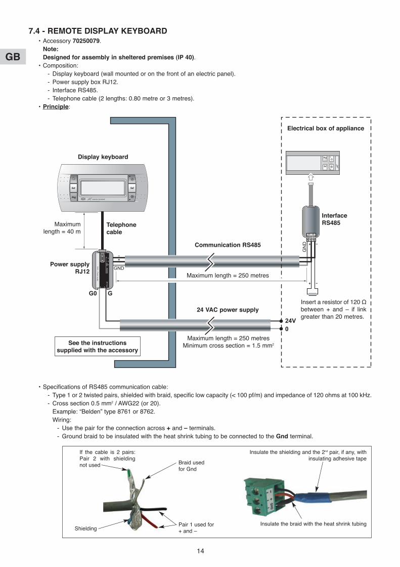
7.4 - REMoTE DISPLAY KEYBoARD• Accessory 70250079.
Note:
Designed for assembly in sheltered premises (IP 40).
• Composition:
- Display keyboard (wall mounted or on the front of an electric panel).
- Power supply box RJ12.
- Interface RS485.
- Telephone cable (2 lengths: 0.80 metre or 3 metres).
• Principle:
24V0
RJ12 – P
ower supply
RS
48524 V
acG0 G
GN
D
–+
GN
D
GND
Electrical box of appliance
Display keyboard
Telephonecable
Power supplyRJ12
InterfaceRS485
Maximum length = 250 metres
Maximum length = 250 metresMinimum cross section = 1.5 mm2
Insert a resistor of 120 Ωbetween + and – if linkgreater than 20 metres.
Maximumlength = 40 m
Communication RS485
24 VAC power supply
See the instructionssupplied with the accessory
• Specifications of RS485 communication cable:
- Type 1 or 2 twisted pairs, shielded with braid, specific low capacity (< 100 pf/m) and impedance of 120 ohms at 100 kHz.
- Cross section 0.5 mm2 / AWG22 (or 20).
Example: “Belden” type 8761 or 8762.
Wiring:
- Use the pair for the connection across + and – terminals.
- Ground braid to be insulated with the heat shrink tubing to be connected to the Gnd terminal.
Insulate the shielding and the 2nd pair, if any, withinsulating adhesive tape
If the cable is 2 pairs:Pair 2 with shieldingnot used
Shielding
Braid usedfor Gnd
Pair 1 used for+ and –
Insulate the braid with the heat shrink tubing
GB
15
• The connection cables should go into the appliance through a grommet (not supplied - drilling to be made).
Make these cables arrive from underneath.
They should go into the electrical box through suitable stuffing boxes (not supplied - drillings to be made).
7.5 - RS 485 CoMMuNICATIoN INTERFACE (For MoDBuS protocol)• Please make enquiries with us.
Caution:
The MoDBuS protocol is not compatible with the remote display keyboard.
8 - STARTING
Before carrying out any work on the installation, make sure that it is switched off and that access to it is prevented.
Any work must be carried out by personnel qualified and authorised to work on this type of machine.
IMPoRTANT NoTE
8.1 - CHECK• That all hydraulic connections are properly tightened and that the hydraulic system functions correctly:
- Purge the circuits.- Position of valves.- Hydraulic pressure (1.5 to 2.5 bar).
• That the water quality:- In order for the heat pump to operate under good conditions and provide optimum performance, it is essential to ensure
that the system’s water circuit is clean. If the water circuit becomes clogged, this will significantly affect the machine’sperformance. The circuit must therefore be cleaned with suitable products in compliance with current standards as soonas it is installed, both for new and renovation work.We recommend the use of products which are compatible with all metals and synthetic materials and approved by officialbodies.Recommendations regarding water quality:
- PH: 7 to 9.- TH: 10 to 20°F.- Dry material in suspension: < 2 g/l.- Granulometry: < 0.4 mm.- Chloride: 50 mg/l maximum.- Conductivity: 150 to 350 µS/cm2.- Fibre: no fibres or fibril.
Any disorder which may occur on our machines due to the poor quality of the fluid in the installation will not be coveredby the warranty.
• That there are no leaks.
• That the machine is stable.
• That the power cables are well fixed to their connection terminals. Terminals that are poorly tightened may causeoverheating and malfunctions.
• That the electric cables are well insulated from any sections of sheet metal or metal parts which could damage them.
• That electrical wiring is a safe distance from refrigeration lines.
• That sensor, control and power cables are properly separated.
• That the machine is earthed.
• That there are neither tools nor other foreign objects in the unit.
8.2 - STARTING-uP THE uNIT• Power up the unit.
• Start the unit.
Caution:
As the unit's power supply is three-phase, make sure that the phase rotation order is correct. If the phase order isnot respected, the phase order controller prevents the unit from operating and causes an alarm. To fix this, simplyinvert the 2 phases.
An indicator lamp on the front panel of the phase order controller (identified as "RSF") indicates the status of thiscontroller:
- Indicator lamp steady = correct phase order.
- Indicator lamp blinking = incorrect order phase
or loss of a phase (Threshold = 70% of voltage rating).

GB
16
8.3 - CHECKS To BE MADE• Water flow-rate:
The generator is fitted with 1/4 SAE pressure taps at the inlet and outlet of the unit to measure headloss using a hydraulicpressure gauge. Use the curves to determine the water flow rate (see § 8.4).
Note:
The generator’s water output must be ensured at all times (particular attention should be paid in the case of control of theterminal units on 2-way valve).
• Pump rotation direction: should a problem occur, invert 2 phases on the pump's power supply.
• Purge the hydraulic system, with special attention given to the pump.
• Water circuit pressure.
• Filter cleanliness.
• Check the HP and LP and check the intensities on the commissioning sheet.
• Check control system operation.
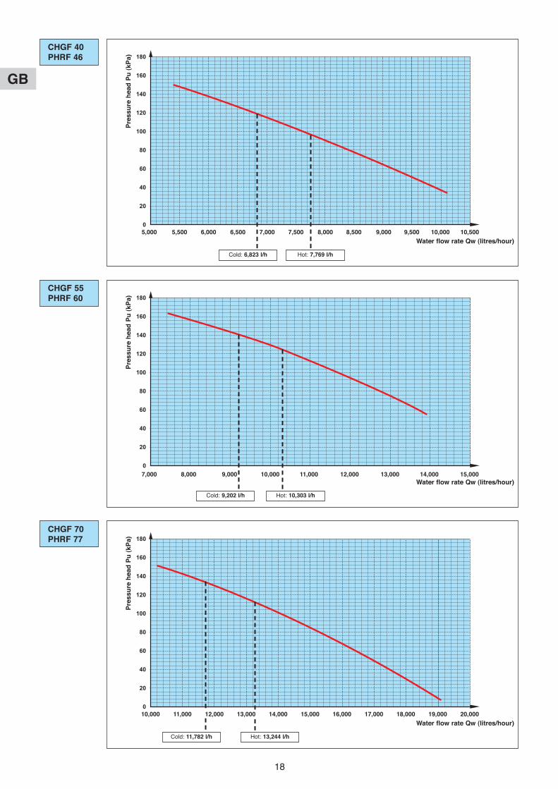
8.4 - PRESSuRE HEAD AVAILABLE• The following diagrams provide the pressure head available of the units (Pu) according to the water flow rate (Qw), for a
water temperature of 10°C. The Y filter (supplied) headlosses are not taken into account.
2500 3000 3500 4000 4500 50000
40
80
120
160
20
60
100
140
180
CHGF 20PHRF 23
Pre
ssu
re h
ea
d P
u (
kP
a)
Water flow rate Qw (litres/hour)
Cold: 3,373 l/h Hot: 3,949 l/h
3000 3500 4000 4500 5000 5500 60000
40
80
120
160
20
60
100
140
180
CHGF 24PHRF 27
Pre
ssu
re h
ead
Pu
(kP
a)
Water flow rate Qw (litres/hour)
Hot: 4,670 l/h
2,500 3,000 3,500 4,000 4,500 5,000
3,000 3,500 4,000 4,500 5,000 5,500 6,000
Cold: 4,094 l/h

GB
17
4000 4500 5000 5500 6000 6500 7000 7500 8000 85000
40
80
120
160
20
60
100
140
180CHGF 28PHRF 32
Pre
ss
ure
he
ad
Pu
(k
Pa
)
Water flow rate Qw (litres/hour)
Hot: 5,396 l/h
4000 4500 5000 5500 6000 6500 7000 7500 8000 85000
40
80
120
160
20
60
100
140
180CHGF 32
Pre
ssu
re h
ead
Pu
(kP
a)
Water flow rate Qw (litres/hour)
Cold: 5,421 l/h
4500 5000 5500 6000 6500 7000 7500 8000 8500 90000
40
80
120
160
20
60
100
140
180PHRF 40
Pre
ssu
re h
ead
Pu
(kP
a)
Water flow rate Qw (litres/hour)
Cold: 6,021 l/h Hot: 6,756 l/h
4,000 4,500 5,000 5,500 6,000 6,500 7,000 7,500 8,000 8,500
4,000 4,500 5,000 5,500 6,000 6,500 7,000 7,500 8,000 8,500
4,500 5,000 5,500 6,000 6,500 7,000 7,500 8,000 8,500 9,000
Cold: 4,833 l/h
GB
18
5000 5500 6000 6500 7000 7500 8000 8500 9000 9500 10000 105000
40
80
120
160
20
60
100
140
180CHGF 40PHRF 46
Pre
ss
ure
he
ad
Pu
(k
Pa
)
Water flow rate Qw (litres/hour)
Hot: 7,769 l/h
7000 8000 9000 10000 11000 12000 13000 14000 150000
40
80
120
160
20
60
100
140
180CHGF 55PHRF 60
Pre
ssu
re h
ead
Pu
(kP
a)
Water flow rate Qw (litres/hour)
Hot: 10,303 l/h
10000 11000 12000 13000 14000 15000 16000 17000 18000 19000 200000
40
80
120
160
20
60
100
140
180CHGF 70PHRF 77
Pre
ssu
re h
ead
Pu
(kP
a)
Water flow rate Qw (litres/hour)
Cold: 11,782 l/h Hot: 13,244 l/h
5,000 5,500 6,000 6,500 7,000 7,500 8,000 8,500 9,000 9,500 10,000 10,500
7,000 8,000 9,000 10,000 11,000 12,000 13,000 14,000 15,000
10,000 11,000 12,000 13,000 14,000 15,000 16,000 17,000 18,000 19,000 20,000
Cold: 6,823 l/h
Cold: 9,202 l/h
GB
19
10000 11000 12000 13000 14000 15000 16000 17000 18000 19000 200000
40
80
120
160
20
60
100
140
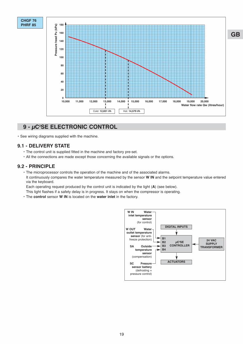
180CHGF 76PHRF 85
Pre
ss
ure
he
ad
Pu
(k
Pa
)
Water flow rate Qw (litres/hour)
Cold: 12,831 l/h Hot: 14,579 l/h
9 - µC2SE ELECTRoNIC CoNTRoL
• See wiring diagrams supplied with the machine.
9.1 - DELIVERY STATE• The control unit is supplied fitted in the machine and factory pre-set.
• All the connections are made except those concerning the available signals or the options.
9.2 - PRINCIPLE• The microprocessor controls the operation of the machine and of the associated alarms.
It continuously compares the water temperature measured by the sensor W IN and the setpoint temperature value enteredvia the keyboard.
Each operating request produced by the control unit is indicated by the light (A) (see below).
This light flashes if a safety delay is in progress. It stays on when the compressor is operating.
• The control sensor W IN is located on the water inlet in the factory.
W IN Waterinlet temperature
sensor(for control)
W ouT Wateroutlet temperature
sensor (for anti-freeze protection)
SA outsidetemperature
sensor(compensation)
SC Pressuresensor battery
(defrosting +pressure control)
DIGITAL INPuTS
µC2SECoNTRoLLER
24 VAC SuPPLY
TRANSFoRMER
ACTuAToRS
B1
B2
B3
B4
10,000 11,000 12,000 13,000 14,000 15,000 16,000 17,000 18,000 19,000 20,000
GB
20
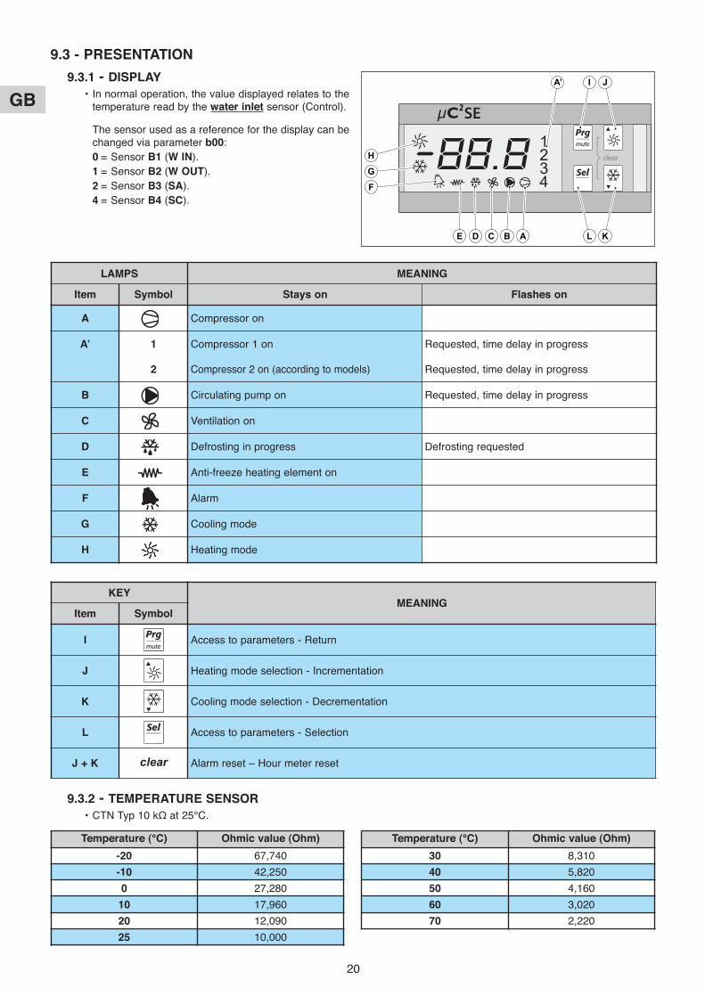
9.3 - PRESENTATIoN
9.3.1 - DISPLAY
• In normal operation, the value displayed relates to thetemperature read by the water inlet sensor (Control).
The sensor used as a reference for the display can bechanged via parameter b00:
0 = Sensor B1 (W IN).
1 = Sensor B2 (W ouT).
2 = Sensor B3 (SA).
4 = Sensor B4 (SC).
H
G
F
E D C B A L K
IA’ J
LAMPS MEANING
Item Symbol Stays on Flashes on
A Compressor on
A’ 1 Compressor 1 on Requested, time delay in progress
2 Compressor 2 on (according to models) Requested, time delay in progress
B Circulating pump on Requested, time delay in progress
C Ventilation on
D Defrosting in progress Defrosting requested
E Anti-freeze heating element on
F Alarm
G Cooling mode
H Heating mode
KEYMEANING
Item Symbol
I Access to parameters - Return
J Heating mode selection - Incrementation
K Cooling mode selection - Decrementation
L Access to parameters - Selection
J + K clear Alarm reset – Hour meter reset
9.3.2 - TEMPERATuRE SENSoR
• CTN Typ 10 kΩ at 25°C.
Temperature (°C) ohmic value (ohm)
-20 67,740
-10 42,250
0 27,280
10 17,960
20 12,090
25 10,000
Temperature (°C) ohmic value (ohm)
30 8,310
40 5,820
50 4,160
60 3,020
70 2,220

GB
21
9.3.4 - MAIN FuNCTIoNS
• Water temperature control.
• Defrosting (reversible appliances).
• Ventilation speed control.
• Alarm management.
• Water circulating pump control.
• Communication.
SA
24 V
WOUT
V PP R Cp
WIN
x
x
AlarmNot used
Temperaturesensors
Variablespeed drive
Ventilation
SC pressure sensor(ratiometric 5 VDC)
InterfaceRS485
(Accessory)
Setting key(not provided)
Remote control(Accessory)
Telemonitoring(not supplied)
or
LP
Wate
rflow
rate
H/C
HP
On
/off
9.3.3 - CoNNECTIoN PRINCIPLE DIAGRAMS
• Controller shown from rear. N
L
N L
SA
24 V
WOUT
PP Cp1Cp2
WIN
x
x
AlarmNot used
Temperaturesensors
Variablespeed drive
Ventilation
SC pressure sensor(ratiometric 5 VDC)
InterfaceRS485
(Accessory)
Remote control(Accessory)
Telemonitoring(not supplied)
or
LP
Wate
rflow
rate
H/C
HP
On/o
ff
N
L
N L
APPLIANCES WITH 1 CoMPRESSoR
APPLIANCES WITH 2 CoMPRESSoRS
Heating element(Cold only)
or valve(Reversible)
Setting key(not provided)
GB
22
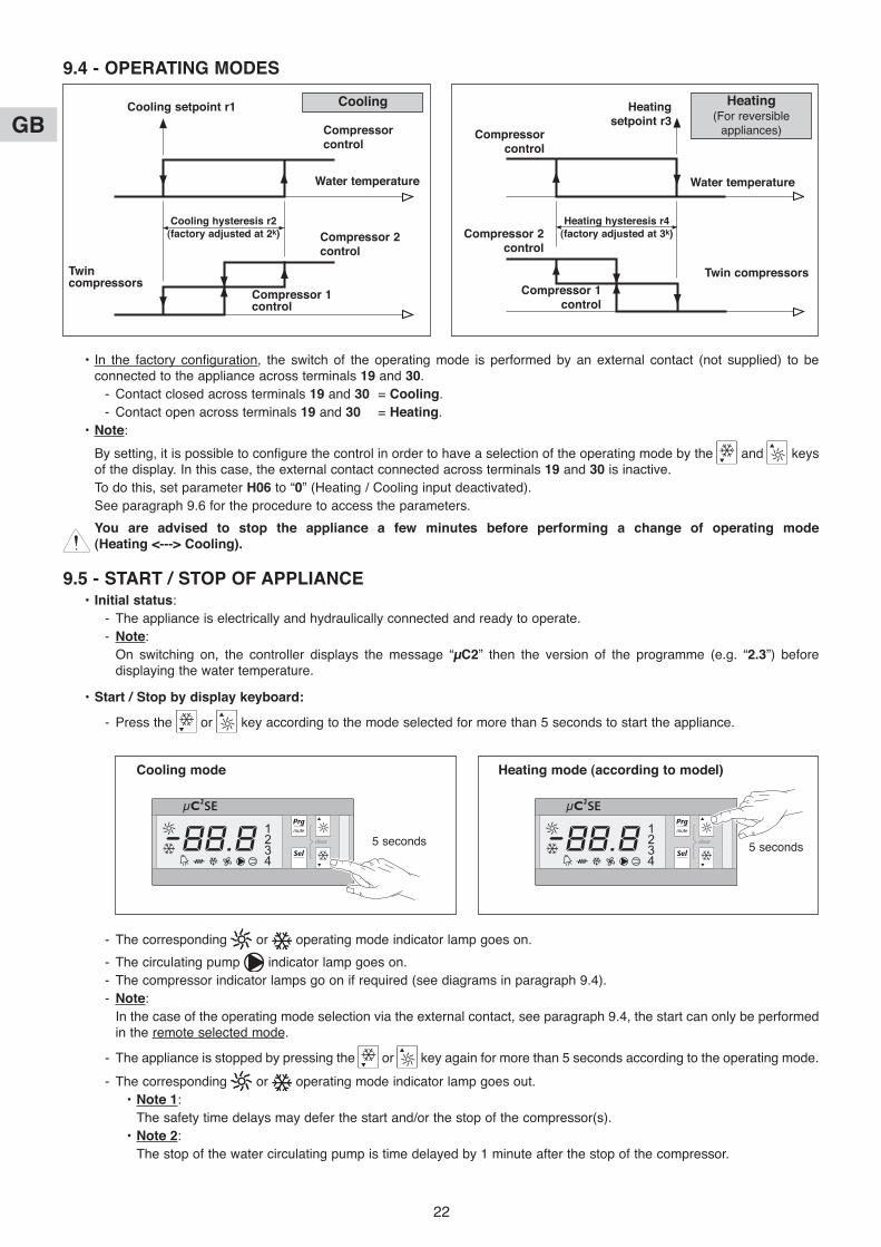
9.4 - oPERATING MoDES
• In the factory configuration, the switch of the operating mode is performed by an external contact (not supplied) to beconnected to the appliance across terminals 19 and 30.
- Contact closed across terminals 19 and 30 = Cooling.
- Contact open across terminals 19 and 30 = Heating.
• Note:
By setting, it is possible to configure the control in order to have a selection of the operating mode by the and keysof the display. In this case, the external contact connected across terminals 19 and 30 is inactive.
To do this, set parameter H06 to “0” (Heating / Cooling input deactivated).
See paragraph 9.6 for the procedure to access the parameters.
You are advised to stop the appliance a few minutes before performing a change of operating mode(Heating <---> Cooling).
9.5 - START / SToP oF APPLIANCE• Initial status:
- The appliance is electrically and hydraulically connected and ready to operate.
- Note:
On switching on, the controller displays the message “µC2” then the version of the programme (e.g. “2.3”) beforedisplaying the water temperature.
• Start / Stop by display keyboard:
- Press the or key according to the mode selected for more than 5 seconds to start the appliance.
- The corresponding or operating mode indicator lamp goes on.
- The circulating pump indicator lamp goes on.
- The compressor indicator lamps go on if required (see diagrams in paragraph 9.4).
- Note:
In the case of the operating mode selection via the external contact, see paragraph 9.4, the start can only be performedin the remote selected mode.
- The appliance is stopped by pressing the or key again for more than 5 seconds according to the operating mode.
- The corresponding or operating mode indicator lamp goes out.
• Note 1:
The safety time delays may defer the start and/or the stop of the compressor(s).
• Note 2:
The stop of the water circulating pump is time delayed by 1 minute after the stop of the compressor.
Compressorcontrol
Compressor 2control
Water temperature
Cooling hysteresis r2(factory adjusted at 2k)
Heating hysteresis r4 (factory adjusted at 3k)
Cooling setpoint r1 Cooling
Compressorcontrol
Compressor 2control
Water temperature
Heatingsetpoint r3
Heating(For reversible
appliances)
5 seconds5 seconds
Cooling mode Heating mode (according to model)
Compressor 1control
Compressor 1control
Twincompressors
Twin compressors

GB
23
• Start / Stop by remote contact:
- By setting, it is possible to configure the control in order to control the appliance via an external contact (not supplied)to be connected to the appliance across terminals 18 and 30.
• Contact open across terminals 18 and 30 = off.
• Contact closed across terminals 18 and 30 = on.
- To do this, set parameter H07 to “1” (On / Off input activated).
See paragraph 9.6 for the procedure to access the parameters.
- This adjustment is required in the case of the use of a simplified remote control 70250078.
Note:
With the appliance on with the remote contact closed, it can be stopped via the key of the display keyboard.
Caution:
In this case, the opening followed by the closing of the remote contact will restart the appliance.
9.6 - PARAMETERS - VIEW AND ADJuSTMENTS
9.6.1 - GENERAL
• The parameter cyclic menu (see following diagram) is accessed in two different ways:
- Either directly by pressing the key for 5 seconds. This provides limited access to view certain values(temperature, hour meters, etc) and adjustment of the setpoints and control differentials.
- Or by a password by simultaneously pressing the and keys for 5 seconds. According to the passwordentered, access is then provided to certain adjustment parameters.
• Setting key function:
: To select the display in progress.
: To scroll the values displayed.
: To exit the display in progress.
The saving of a parameter change is not made until you leave the menu by pressing the key.
• To save the parameters:
Press twice, then once to exit the menu.
• How not to save parameters:
Do not press any key for 60 seconds until the temperature display returns.

GB
24
9.6.2 - ARCHITECTuRE oF PARAMETER MENu
• Access to parameters by password:
- Press: + for 5 seconds.
- On display of: , release the + keys.
- With the arrows: and , enter the password.
- Press: to confirm the password.
- Display of: (Set Parameters).
- Press: to enter into the parameters.
Water inlettemperature
normaldisplay
Passwordcode
For 5 seconds
5 seconds
PASSWoRD DIRECT ACCESS
Parametermodification
Access levelmodification
Sensorparameters
Softwareparameters
Controlparameters
Alarmparameters
Machineparameters
Fanparameters
Defrostingparameters
Compressorparameters
Sensorreading
Anti-freezeparameters
F1parameters
Value of F1 Access level
Fnparameters
If entry into parameterswith L-P
GB
25
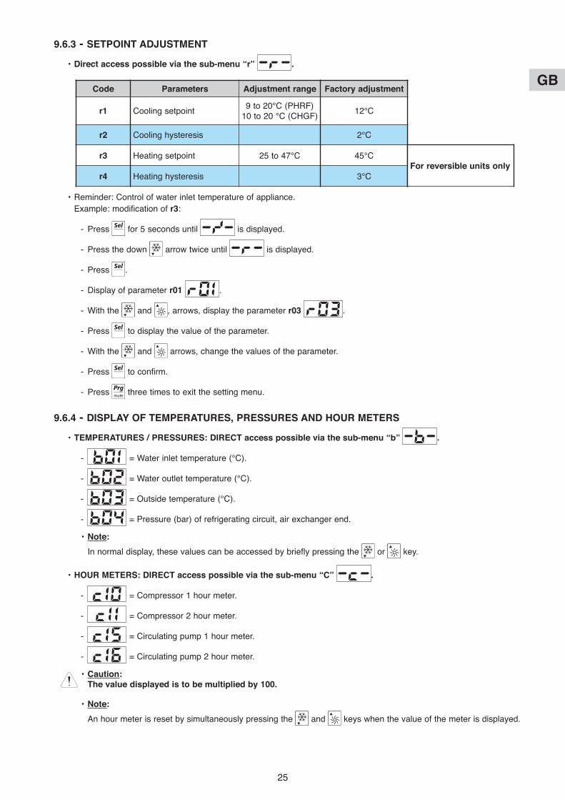
9.6.3 - SETPoINT ADJuSTMENT
• Direct access possible via the sub-menu “r” .
• Reminder: Control of water inlet temperature of appliance.
Example: modification of r3:
- Press for 5 seconds until is displayed.
- Press the down arrow twice until is displayed.
- Press .
- Display of parameter r01 .
- With the and , arrows, display the parameter r03 .
- Press to display the value of the parameter.
- With the and arrows, change the values of the parameter.
- Press to confirm.
- Press three times to exit the setting menu.
9.6.4 - DISPLAY oF TEMPERATuRES, PRESSuRES AND HouR METERS
• TEMPERATuRES / PRESSuRES: DIRECT access possible via the sub-menu “b” .
- = Water inlet temperature (°C).
- = Water outlet temperature (°C).
- = Outside temperature (°C).
- = Pressure (bar) of refrigerating circuit, air exchanger end.
• Note:
In normal display, these values can be accessed by briefly pressing the or key.
• HouR METERS: DIRECT access possible via the sub-menu “C” .
- = Compressor 1 hour meter.
- = Compressor 2 hour meter.
- = Circulating pump 1 hour meter.
- = Circulating pump 2 hour meter.
• Caution:The value displayed is to be multiplied by 100.
• Note:
An hour meter is reset by simultaneously pressing the and keys when the value of the meter is displayed.
Code Parameters Adjustment range Factory adjustment
r1 Cooling setpoint9 to 20°C (PHRF)
10 to 20 °C (CHGF)12°C
r2 Cooling hysteresis 2°C
r3 Heating setpoint 25 to 47°C 45°C
r4 Heating hysteresis 3°CFor reversible units only
GB
26
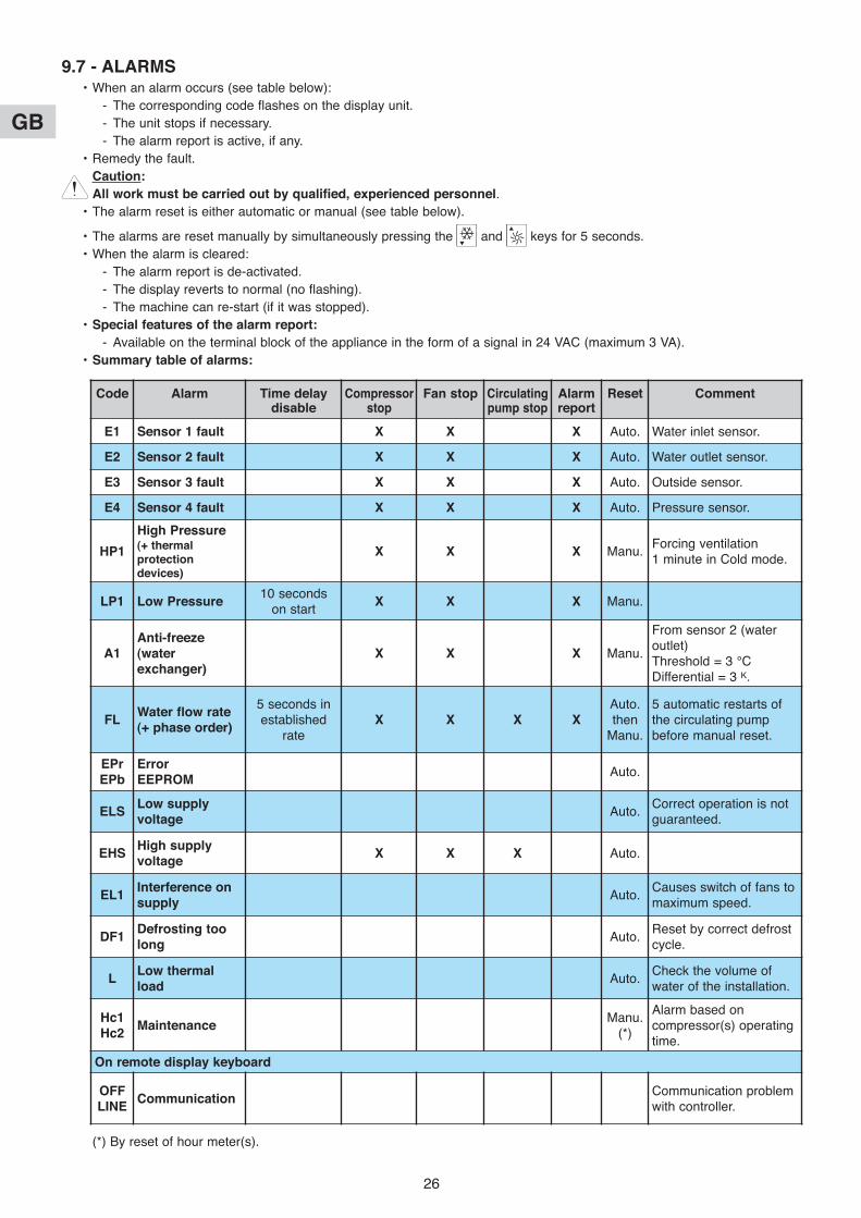
9.7 - ALARMS• When an alarm occurs (see table below):
- The corresponding code flashes on the display unit.
- The unit stops if necessary.
- The alarm report is active, if any.
• Remedy the fault.
Caution:
All work must be carried out by qualified, experienced personnel.
• The alarm reset is either automatic or manual (see table below).
• The alarms are reset manually by simultaneously pressing the and keys for 5 seconds.
• When the alarm is cleared:
- The alarm report is de-activated.
- The display reverts to normal (no flashing).
- The machine can re-start (if it was stopped).
• Special features of the alarm report:
- Available on the terminal block of the appliance in the form of a signal in 24 VAC (maximum 3 VA).
• Summary table of alarms:
Code Alarm Time delaydisable
Compressorstop
Fan stop Circulatingpump stop
Alarmreport
Reset Comment
E1 Sensor 1 fault x x x Auto. Water inlet sensor.
E2 Sensor 2 fault x x x Auto. Water outlet sensor.
E3 Sensor 3 fault x x x Auto. Outside sensor.
E4 Sensor 4 fault x x x Auto. Pressure sensor.
HP1
High Pressure(+ thermalprotectiondevices)
x x x Manu.Forcing ventilation 1 minute in Cold mode.
LP1 Low Pressure10 seconds
on startx x x Manu.
A1Anti-freeze(waterexchanger)
x x x Manu.
From sensor 2 (wateroutlet)Threshold = 3 °CDifferential = 3 K.
FLWater flow rate(+ phase order)
5 seconds inestablished
ratex x x x
Auto.then
Manu.
5 automatic restarts ofthe circulating pumpbefore manual reset.
EPrEPb
Error EEPRoM
Auto.
ELSLow supplyvoltage
Auto.Correct operation is notguaranteed.
EHSHigh supplyvoltage
x x x Auto.
EL1Interference onsupply
Auto.Causes switch of fans tomaximum speed.
DF1Defrosting toolong
Auto.Reset by correct defrostcycle.
LLow thermalload
Auto.Check the volume ofwater of the installation.
Hc1Hc2
MaintenanceManu.
(*)
Alarm based oncompressor(s) operatingtime.
on remote display keyboard
oFFLINE
CommunicationCommunication problemwith controller.
(*) By reset of hour meter(s).

GB
27
9.8 - oPERATING FEATuRES
9.8.1 - ANTI-FREEzE PRoTECTIoN oF WATER CIRCuIT
• 2 functions performed:
- Heating element control (on water exchanger, pumpbody and tank).
- Anti-freeze alarm stopping the machine.
• Operating diagram (see opposite).
The adjustment of these thresholds can be modified onrequest according to the conditions of use of themachine.
(*) For reversible appliances with 2 compressors, theheating elements are controlled by a separatethermostat (factory adjustment = 3°C, hysteresis = 3k)in the electrical box of the appliance.
9.8.2 - CIRCuLATING PuMP CoNTRoL
• The pump is controlled as soon as the appliance is started.
• The pump stops when the appliance is stopped after a time delay (1 minute after the stop of the compressor).
9.8.3 - REMoTE CoNTRoLS
• 2 possibilities:
- Simplified control 70250078:
- Uses the control inputs by On / Off and Hot / Cold contacts.
- The control alarm report controls an indicatorlamp on the remote control.
- See connection diagram in paragraph 9.3.
- See the instructions supplied with the control.
- Designed for assembly in sheltered premises(IP 20).
- Remote display keyboard 70250079:
- The functions are identical to those of thedisplay keyboard on the front of the appliance.
- The remote display keyboard uses thecommunication link of the control (*).
- See connection diagram in paragraph 9.3.
- See the instructions supplied with the remotedisplay keyboard.
- Designed for assembly in sheltered premises(IP 40).
- Specific keys:
: Alarm clear.
: Access to parameters.
Note:The H23 parameter must be set at “0” (= CAREL protocol) in order for the remote display keyboard to operatecorrectly.
9.8.4 - PoWER CuT
• If the power is cut to the control circuits, the electronic control unit returns to the operating mode it was in before thepower was cut and the parameters are still stored in memory when the power is restored.
0°C
1
1
1°C 2°C 3°C 4°C 5°C 6°C
A05
A02Freeze alarm
Heating elementcontrol (*)
Parameters: Threshold A01
Parameters: Threshold A04
(*) No MODBUS protocol with the remote display keyboard.
GB
28
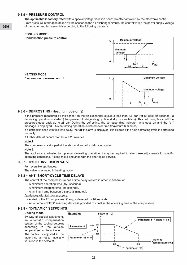
9.8.5 - PRESSuRE CoNTRoL
• The applicable is factory fitted with a special voltage variation board directly controlled by the electronic control.
• From pressure information (taken by the sensor on the air exchanger circuit), the control varies the power supply voltageof the motor and fan assembly according to the following diagrams.
• CooLING MoDE:
Condensation pressure control
• HEATING MoDE:
Evaporation pressure control
9.8.6 - DEFRoSTING (Heating mode only)
• If the pressure measured by the sensor on the air exchanger circuit is less than 4.5 bar (for at least 60 seconds), adefrosting operation is started (change-over of refrigerating cycle and stop of ventilation). This defrosting lasts until thepressures goes back up to 28 bar. During the defrosting, the corresponding indicator lamp goes on and the “d1”message is displayed. This defrosting operation is limited over time (maximum 6 minutes).
If a defrost finishes with this time delay, the “dF1” alarm is displayed. It is cleared if the next defrosting cycle is performednormally.
A further defrost cannot start before 20 minutes.
Note 1:
The compressor is stopped at the start and end of a defrosting cycle.
Note 2:
The appliance is adjusted for optimum defrosting operation. It may be required to alter these adjustments for specificoperating conditions. Please make enquiries with the after-sales service.
9.8.7 - CYCLE INVERSIoN VALVE
• For reversible appliances.
• The valve is actuated in heating mode.
9.8.8 - ANTI SHoRT-CYCLE TIME DELAYS
• The control of the compressor(s) has a time delay system in order to adhere to:
- A minimum operating time (150 seconds).
- A minimum stopping time (60 seconds).
- A minimum time between 2 starts (6 minutes).
• Appliances with twin compressors:
- A start of the 2nd compressor, if any, is deferred by 10 seconds.
- An automatic “FIFO” switching device is provided to equalise the operating time of the compressors.
9.8.9 - "DYNAMIC" SETPoINTS
• Cooling mode:
By way of special adjustment,an automatic compensationsystem of the cooling setpointaccording to the outsidetemperature can be activated.
The control is adjusted in thefactory so as not to have anyvariation in the setpoint.
U
0P(Bar)7.6 920.2
Maximum voltage
Minimumvoltage
U
0
2 110 P(Bar)
Maximum voltage
Minimum voltage
15
12
30 36
Setpoint (°C)
outsidetemperature (°C)
Parameter r17 slope = -0,5
Parameter r1
Parameter r18 = 3k
Parameter r19
Example:

GB
29
• Heating mode:
The control is factory adjustedto have the appliance operatewithin its operating limits whenthe outside temperature drops.
9.8.10 - REDuCTIoN oF WATER VoLuME
• The controller has an auto-adaptive algorithm which analyses the operating times of the compressor and can induce analteration of the temperature control hysteresis in the event of operating time which is too short (in order to extend theoperating times).
• For special applications, in which case the dimensioning of the unit and the circuit are carefully designed, this functioncan be deactivated. In order to do this, set parameter r27 to “0” in the "-r-" control section of the adjustment menu.
9.8.11 - MAINTENANCE ALARM
• An alarm threshold on the compressor(s) operating time can be adjusted via parameter C14.
• This threshold is expressed in hundreds of hours.
• By default, this parameter is set at “0” (function deactivated).
9.8.12 - CoMMuNICATIoN
• The control can be connected to a supervision system thanks to the communication interface RS485 MoDBuSProtocol accessory 70250080 (Please make enquiries with us for the list of communication addresses andspecifications).
In this case, parameter H23 must be set at “1” (MODBUS).
Also complete parameter H10: Series address.
9.8.13 - MISCELLANEouS PARAMETERS
• Calibration of the values read by the sensors:
/13 : Input B1 (W IN).
/14 : Input B2 (W ouT).
/15 : Input B3 (SA).
/16 : Input B4 (SC).
• Measurement units:
/23 : 0 = degrees Celsius (default value).
1 = degrees Fahrenheit.
• Software programme version: H99.
Important:
• This accessory must be used without the remote display keyboard.
• The (“Hardware” and “Software”) supervision system is not supplied.
45
37
-10 -4.5 7
Setpoint (°C)
outsidetemperature (°C)
Parameter r31 slope = +0,7
Parameter r3
Parameter r18 = 8k
Parameter r20
Factory adjustment:

GB
30
10.2 - oPERATING LIMITS IN HEAT PuMP MoDE
-1
0
1
2
3
4
5
6
7
8
9
10
11
12
13
14
15
16
-12 -10 -8 -6 -4 -2 0 2 4 6 8 10 12 14 16 18 20 22 24 26 28 30 32 34 36 38 40 42 44 46
CHGV 20/76
outside dry bulb temperature (C°)
Water outlet temperature (C°)
-1
0
1
2
3
4
5
6
7
8
9
10
11
12
13
14
15
16
-12 -10 -8 -6 -4 -2 0 2 4 6 8 10 12 14 16 18 20 22 24 26 28 30 32 34 36 38 40 42 44 46
PHRF 23/85
outside dry bulb temperature (C°)
Water outlet temperature (C°)
With glycol
With glycol
10 - oPERATING LIMITS
The following graphs show the continuous operating limits according to the water outlet temperature of the unit and the outsideair temperature.
Caution:
The units are designed to operate when the water and air temperatures are below the limits laid down. The unit may incurirreparable damage beyond these limits.
10.1 - oPERATING LIMITS IN CHILLER oPERATING MoDE
23
25
27
29
31
33
35
37
39
41
43
45
47
49
51
53
55
-12 -11 -10 -9 -8 -7 -6 -5 -4 -3 -2 -1 0 1 2 3 4 5 6 7 8 9 10 11 12 13 14 15 16 17 18 19 20 21 22
PHRF 23/85
outside dry bulb temperature (C°)
Water outlet temperature (C°)
GB
31
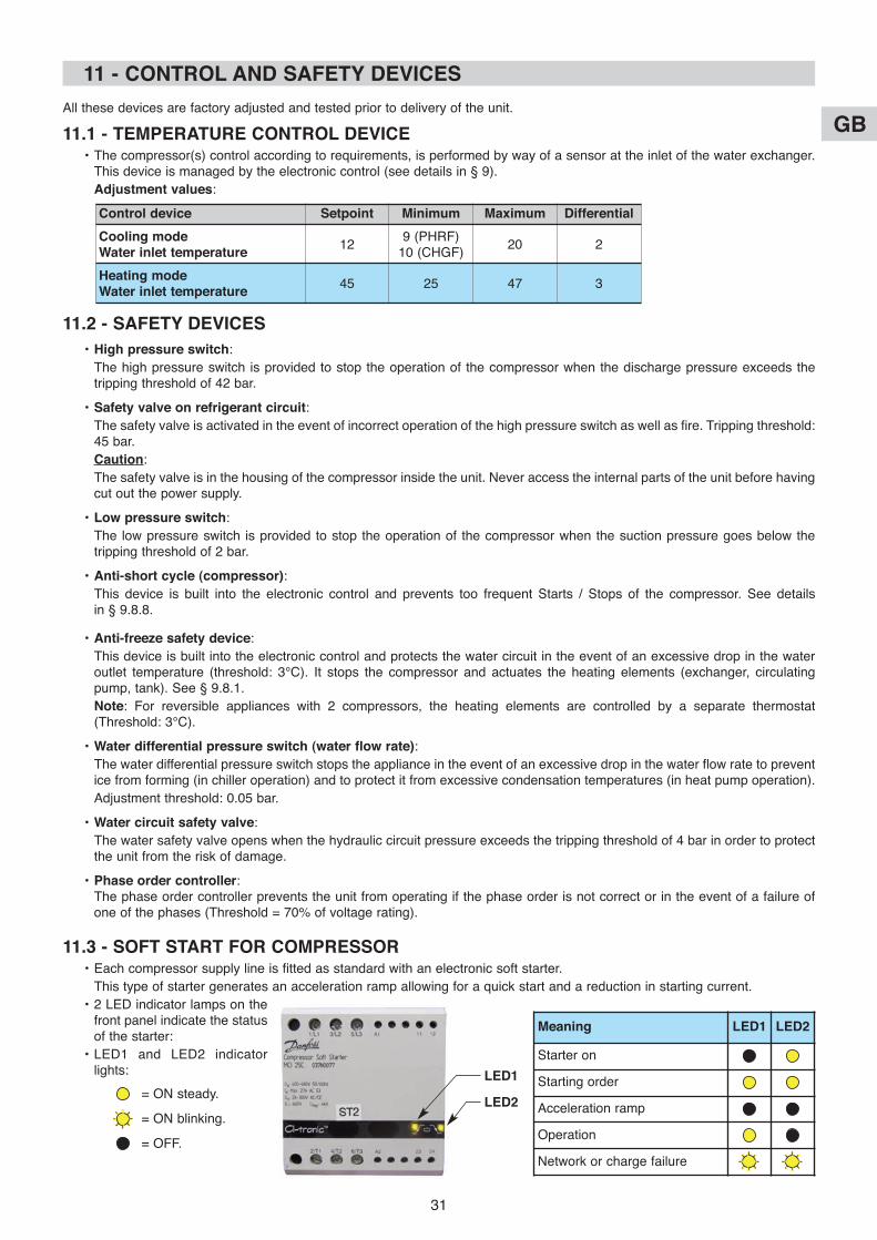
11 - CoNTRoL AND SAFETY DEVICES
All these devices are factory adjusted and tested prior to delivery of the unit.
11.1 - TEMPERATuRE CoNTRoL DEVICE• The compressor(s) control according to requirements, is performed by way of a sensor at the inlet of the water exchanger.
This device is managed by the electronic control (see details in § 9).
Adjustment values:
11.2 - SAFETY DEVICES
• High pressure switch:
The high pressure switch is provided to stop the operation of the compressor when the discharge pressure exceeds thetripping threshold of 42 bar.
• Safety valve on refrigerant circuit:
The safety valve is activated in the event of incorrect operation of the high pressure switch as well as fire. Tripping threshold:45 bar.
Caution:
The safety valve is in the housing of the compressor inside the unit. Never access the internal parts of the unit before havingcut out the power supply.
• Low pressure switch:
The low pressure switch is provided to stop the operation of the compressor when the suction pressure goes below thetripping threshold of 2 bar.
• Anti-short cycle (compressor):
This device is built into the electronic control and prevents too frequent Starts / Stops of the compressor. See details in § 9.8.8.
• Anti-freeze safety device:
This device is built into the electronic control and protects the water circuit in the event of an excessive drop in the wateroutlet temperature (threshold: 3°C). It stops the compressor and actuates the heating elements (exchanger, circulatingpump, tank). See § 9.8.1.
Note: For reversible appliances with 2 compressors, the heating elements are controlled by a separate thermostat(Threshold: 3°C).
• Water differential pressure switch (water flow rate):
The water differential pressure switch stops the appliance in the event of an excessive drop in the water flow rate to preventice from forming (in chiller operation) and to protect it from excessive condensation temperatures (in heat pump operation).
Adjustment threshold: 0.05 bar.
• Water circuit safety valve:
The water safety valve opens when the hydraulic circuit pressure exceeds the tripping threshold of 4 bar in order to protectthe unit from the risk of damage.
• Phase order controller:The phase order controller prevents the unit from operating if the phase order is not correct or in the event of a failure ofone of the phases (Threshold = 70% of voltage rating).
11.3 - SoFT START FoR CoMPRESSoR• Each compressor supply line is fitted as standard with an electronic soft starter.
This type of starter generates an acceleration ramp allowing for a quick start and a reduction in starting current.
• 2 LED indicator lamps on thefront panel indicate the statusof the starter:
• LED1 and LED2 indicatorlights:
= ON steady.
= ON blinking.
= OFF.
Control device Setpoint Minimum Maximum Differential
Cooling mode Water inlet temperature
129 (PHRF)
10 (CHGF)20 2
Heating mode Water inlet temperature
45 25 47 3
Meaning LED1 LED2
Starter on
Starting order
Acceleration ramp
Operation
Network or charge failure
LED1
LED2
GB
32
• Check for the correct operation of the safety devices (pressure switches and safety valves) on a periodical basis and that thereare no refrigerant leaks.
After the first start up, periodical inspections should be performed according to the frequencies and in the modes laid down bythe national regulations in force.
In order to guarantee correct operating conditions of the unit and obtain the performance and levels of safety provided for, acertain amount of checks should be performed on a regular basis. Some of them can be performed by the user, others requireoperations from a qualified technician.
• Checks by the user:
The operations and checks described in this chapter can be carried out without difficulty by the user taking a minimum ofprecautions.
- Remove any built up dirt on the battery or its protection grid (leaves, paper, etc.., to be carried out every month).
Caution:
Be extremely careful when conducting operations near aluminium finned batteries to prevent any risks of getting cut.
- Check the filling of the water circuit on the corresponding pressure gauge, it should show pressure of approximately 1.5 bar(monthly check).
- Check that the pipe of the water safety valve is securely fixed.
- Check there are no water leaks on the hydraulic circuit (monthly check).
- If prolonged shut-down of the unit is scheduled, discharge the water (or other fluids) in the pipes and the circuit of the unit.
This operation is vital in the event when an ambient temperature lower than the freezing point of the fluid used is expectedduring the shut-down period (operation to be carried out at the end of the season of use). Drain the unit and the part of thecircuit exposed to the risk.
• Checks and maintenance entrusted to qualified personnel:
- Carry out the following operations at least once a year (the frequency depends on the installation and operatingconditions):
- Check for leaks on the refrigerating circuit.
- Check for traces of corrosion or oil stains around the refrigerating components.
- Inspect the composition and the condition of the coolant and check that it does not contain traces of refrigerating fluid.
- Cleaning the exchangers.
- Checking the wear parts.
- Checking the operating instructions and points.
- Check the safety devices: particularly check that the high and low-pressure controllers are properly connected on therefrigerating circuit and that they disengage the electrical circuit if triggered.
- De-dusting the electrical equipment cabinet.
- Checking that the electrical connections are secure.
- Checking the earth connection.
- Check the hydraulic circuit (clean the filter, water quality, purge, flowrate, pressure, etc...).
- Verification of the unit's safety valve (and that of the tank, if any).
• When the unit has reached the end of its scheduled service life, when it must be dismantled or replaced, proceed as follows:
- The refrigerant gas contained inside it must be recovered by a qualified technician and handed over to a collection centre.
- The lubrication oil of the compressor must be recovered by a qualified technician and handed over to a collection centre.
- The structure and different components that cannot be reused must be disposed of through waste collection: this operationparticularly applies to copper, aluminium and steel and significant quantities of metal in the unit. All these operations areaimed at facilitating the collection, disposal and recycling procedures as well as minimizing the impact on the environment.
13 - RECYCLING
12 - MAINTENANCE INSTRuCTIoNS
• Before doing any work on the machine, make sure that it is switched off and locked out, with special attentiongiven in the case of a tank with supplementary heating (different power supplies).
• Any work must be carried out by personnel qualified and authorised to work on this type of machine.
• Prior to all maintenance and servicing on the refrigerating circuit, one must first shut down the unit then wait afew minutes before installing temperature or pressure sensors. Certain equipment, such as the compressor andpiping, may reach temperatures above 100°C and high pressures may lead to serious burns.
IMPoRTANT NoTE
GB
33
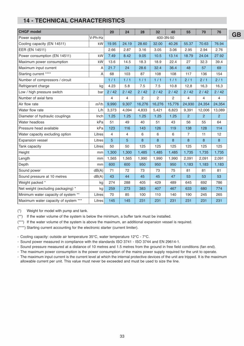
14 - TECHNICAL CHARACTERISTICS
CHGF model 20 24 28 32 40 55 70 76
Power supply V-Ph-Hz 400-3N-50
Cooling capacity (EN 14511) kW 19.95 24.19 28.60 32.00 40.26 55.37 70.63 76.94
EER (EN 14511) 2.66 2.87 3.16 3.05 3.06 2.95 2.94 2.76
Power consumption (EN 14511) kW 7.49 8.42 9.05 10.5 13.14 18.79 24.04 27.92
Maximum power consumption kW 13.6 14.5 18.3 18.9 22.4 27 32.3 39.4
Maximum input current A 21.7 24 28.6 32.4 36.4 48 57 69
Starting current **** A 68 103 87 108 108 117 136 154
Number of compressors / circuit 1 / 1 1 / 1 1 / 1 1 / 1 1 / 1 2 / 1 2 / 1 2 / 1
Refrigerant charge kg 4.23 5.8 7.5 7.5 10.8 12,8 16,3 16,3
Low / high pressure switch bar 2 / 42 2 / 42 2 / 42 2 / 42 2 / 42 2 / 42 2 / 42 2 / 42
Number of axial fans 4 4 2 2 2 4 4 4
Air flow rate m3/h 9,990 9,307 16,276 16,276 15,776 24,930 24,354 24,354
Water flow rate L/h 3,373 4,094 4,833 5,421 6,823 9,391 12,006 13,089
Diameter of hydraulic couplings Inch 1.25 1.25 1.25 1.25 1.25 2 2 2
Water headloss kPa 51 49 40 51 43 56 55 64
Pressure head available kPa 123 116 143 126 119 138 128 114
Water capacity excluding option Litres 4 4 6 6 6 7 11 12
Expansion vessel Litres 5 5 8 8 8 8 8 8
Tank capacity Litres 50 50 125 125 125 125 125 125
Height mm 1,300 1,300 1,485 1,485 1,485 1,735 1,735 1,735
Length mm 1,565 1,565 1,990 1,990 1,990 2,091 2,091 2,091
Depth mm 600 600 950 950 950 1,183 1,183 1,183
Sound power dB(A) 71 72 73 73 75 81 81 81
Sound pressure at 10 metres dB(A) 43 44 45 45 47 53 53 53
Weight packed * kg 274 288 405 429 489 645 692 786
Net weight (excluding packaging) * kg 259 273 383 407 467 633 680 774
Minimum water capacity of system ** Litres 70 85 100 110 140 190 245 265
Maximum water capacity of system *** Litres 145 145 231 231 231 231 231 231
(*) Weight for model with pump and tank.
(**) If the water volume of the system is below the minimum, a buffer tank must be installed.
(***) If the water volume of the system is above the maximum, an additional expansion vessel is required.
(****) Starting current accounting for the electronic starter (current limiter).
- Cooling capacity: outside air temperature 35°C, water temperature 12°C - 7°C.
- Sound power measured in compliance with the standards ISO 3741 - ISO 3744 and EN 29614-1.
- Sound pressure measured at a distance of 10 metres and 1.5 metres from the ground in free field conditions (fan end).
- The maximum power consumption is the power consumption of the mains power supply required for the unit to operate.
- The maximum input current is the current level at which the internal protective devices of the unit are tripped. It is the maximumallowable current per unit. This value must never be exceeded and must be used to size the line.
GB
34
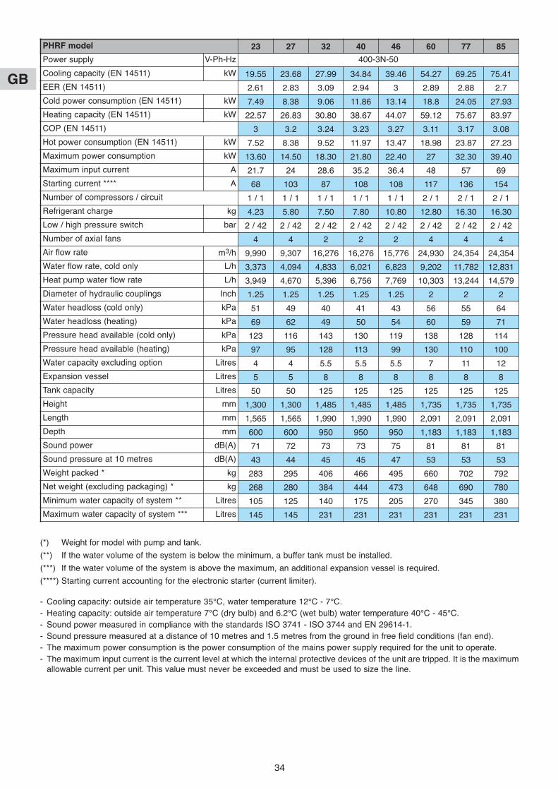
PHRF model 23 27 32 40 46 60 77 85
Power supply V-Ph-Hz 400-3N-50
Cooling capacity (EN 14511) kW 19.55 23.68 27.99 34.84 39.46 54.27 69.25 75.41
EER (EN 14511) 2.61 2.83 3.09 2.94 3 2.89 2.88 2.7
Cold power consumption (EN 14511) kW 7.49 8.38 9.06 11.86 13.14 18.8 24.05 27.93
Heating capacity (EN 14511) kW 22.57 26.83 30.80 38.67 44.07 59.12 75.67 83.97
COP (EN 14511) 3 3.2 3.24 3.23 3.27 3.11 3.17 3.08
Hot power consumption (EN 14511) kW 7.52 8.38 9.52 11.97 13.47 18.98 23.87 27.23
Maximum power consumption kW 13.60 14.50 18.30 21.80 22.40 27 32.30 39.40
Maximum input current A 21.7 24 28.6 35.2 36.4 48 57 69
Starting current **** A 68 103 87 108 108 117 136 154
Number of compressors / circuit 1 / 1 1 / 1 1 / 1 1 / 1 1 / 1 2 / 1 2 / 1 2 / 1
Refrigerant charge kg 4.23 5.80 7.50 7.80 10.80 12.80 16.30 16.30
Low / high pressure switch bar 2 / 42 2 / 42 2 / 42 2 / 42 2 / 42 2 / 42 2 / 42 2 / 42
Number of axial fans 4 4 2 2 2 4 4 4
Air flow rate m3/h 9,990 9,307 16,276 16,276 15,776 24,930 24,354 24,354
Water flow rate, cold only L/h 3,373 4,094 4,833 6,021 6,823 9,202 11,782 12,831
Heat pump water flow rate L/h 3,949 4,670 5,396 6,756 7,769 10,303 13,244 14,579
Diameter of hydraulic couplings Inch 1.25 1.25 1.25 1.25 1.25 2 2 2
Water headloss (cold only) kPa 51 49 40 41 43 56 55 64
Water headloss (heating) kPa 69 62 49 50 54 60 59 71
Pressure head available (cold only) kPa 123 116 143 130 119 138 128 114
Pressure head available (heating) kPa 97 95 128 113 99 130 110 100
Water capacity excluding option Litres 4 4 5.5 5.5 5.5 7 11 12
Expansion vessel Litres 5 5 8 8 8 8 8 8
Tank capacity Litres 50 50 125 125 125 125 125 125
Height mm 1,300 1,300 1,485 1,485 1,485 1,735 1,735 1,735
Length mm 1,565 1,565 1,990 1,990 1,990 2,091 2,091 2,091
Depth mm 600 600 950 950 950 1,183 1,183 1,183
Sound power dB(A) 71 72 73 73 75 81 81 81
Sound pressure at 10 metres dB(A) 43 44 45 45 47 53 53 53
Weight packed * kg 283 295 406 466 495 660 702 792
Net weight (excluding packaging) * kg 268 280 384 444 473 648 690 780
Minimum water capacity of system ** Litres 105 125 140 175 205 270 345 380
Maximum water capacity of system *** Litres 145 145 231 231 231 231 231 231
(*) Weight for model with pump and tank.
(**) If the water volume of the system is below the minimum, a buffer tank must be installed.
(***) If the water volume of the system is above the maximum, an additional expansion vessel is required.
(****) Starting current accounting for the electronic starter (current limiter).
- Cooling capacity: outside air temperature 35°C, water temperature 12°C - 7°C.
- Heating capacity: outside air temperature 7°C (dry bulb) and 6.2°C (wet bulb) water temperature 40°C - 45°C.
- Sound power measured in compliance with the standards ISO 3741 - ISO 3744 and EN 29614-1.
- Sound pressure measured at a distance of 10 metres and 1.5 metres from the ground in free field conditions (fan end).
- The maximum power consumption is the power consumption of the mains power supply required for the unit to operate.
- The maximum input current is the current level at which the internal protective devices of the unit are tripped. It is the maximumallowable current per unit. This value must never be exceeded and must be used to size the line.
GB
35
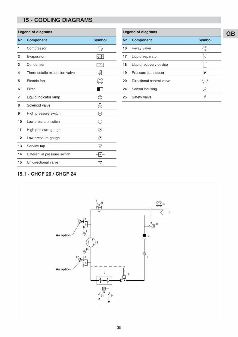
15 - CooLING DIAGRAMS
Legend of diagrams
Nr. Component Symbol
1 Compressor
2 Evaporator
3 Condenser
4 Thermostatic expansion valve
5 Electric fan
6 Filter
7 Liquid indicator lamp
8 Solenoid valve
9 High pressure switch
10 Low pressure switch
11 High pressure gauge
12 Low pressure gauge
13 Service tap
14 Differential pressure switch
15 Unidirectional valve
Legend of diagrams
Nr. Component Symbol
16 4-way valve
17 Liquid separator
18 Liquid recovery device
19 Pressure transducer
20 Directional control valve
24 Sensor housing
25 Safety valve
15.1 - CHGF 20 / CHGF 24
As option
As option
GB
36
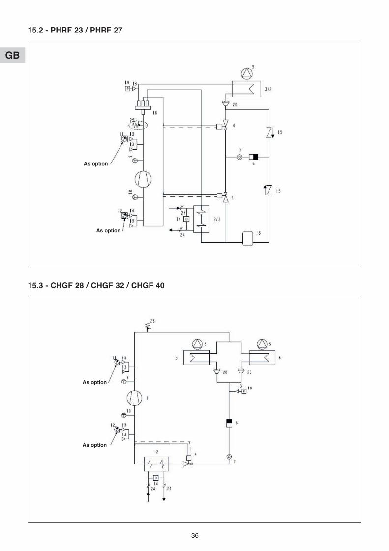
15.2 - PHRF 23 / PHRF 27
15.3 - CHGF 28 / CHGF 32 / CHGF 40
As option
As option
As option
As option

GB
37
15.4 - PHRF 32 / PHRF 40 / PHRF 46
15.5 - CHGF 55 / CHGF 70 / CHGF 76
As option
As option
As option
As option

GB
38
15.6 - PHRF 60 / PHRF 77 / PHRF 85
As option
As option
Caution:
Be extremely careful when carrying out any operations on the unit. Insufficient precaution could cause seriousaccidents for non-expert persons.
• All maintenance and servicing operations on the refrigerating circuit must be conducted in accordance with standard tradepractices and safety rules: recovery of the refrigerant, inert shielded (nitrogen) brazing, etc…
• All brazing operations must be conducted by qualified welders.
• For equipment loaded with R 410 A, refer to the specific instructions at the beginning of the installation manual.
• This unit is equipped with pressurized equipment, for example piping.
Use only genuine parts listed in the spare parts list for replacing defective refrigeration components.
• Pipes may only be replaced by copper tubing in compliance with standard NF EN 12735-1.
• Leak detection, in the case of pressure testing:
- Never use oxygen or dry air, as the risk of fire or explosion is present.
- Use dehydrated nitrogen or a nitrogen and refrigerant mix indicated on the manufacturer's plate.
- For units equipped with pressure gauges, the test pressure must not exceed the gauges' maximum allowable pressurerating.
• All part replacement with other than genuine parts, all modifications of the refrigerating circuit, all replacement of refrigerant bya fluid other than that indicated on the manufacturer's plate, all use of the unit outside the application limits defined in thedocumentation, shall result in the cancellation of PED CE marking compliance which shall fall under the liability of the individualwho carried out these modifications.
• The technical information, relative to the safety requirements of the various applicable directives, is indicated on themanufacturer's plate of the unit and mentioned on the 1st page of this manual.
• The following table shows the most common causes of failure or incorrect operation of the appliance. The possible operationsare given for the most obvious anomalies.
Operations marked with a “U” can be carried out by the user in accordance with the instructions given herein.
Those marked with a “T” must be entrusted to a qualified technician. You are advised to contact the After-Sales Service oncethe cause of the anomaly has been established.
u = user. T = Qualified technician.
16 - TRouBLESHooTING

GB
39
Problems Cold Hot operationcompetence
u = userT = Qualified
technician
Messageon
controllerif any
Possible cause operation
AThe unit does notstart.
x x T ELSEHS(FL)
No power.
Faulty connection.
Incorrect voltage.
Check for presence and value of
voltage.
Check the order of the phases.
x x T FL Water flow rate problem. Check the operation of the water
circulating pump, pressure
switch, bleed the circuit.
Check the closing of the water
flow rate contact (terminals
16/30).
x x u Flashingicon
Time delay in progress. Wait a few minutes.
x x T E1 Faulty control sensor. Check and change the sensor if
required.
x x u No control signal from
compressor.
Temperature installation.
Check the setpoint adjustment.
x x T A1 Anti-freeze safety device. Check the water flow rate.
Check the water temperature.
Check the adjustment of the anti-
freeze threshold.
x x T E2 Faulty anti-freeze sensor. Check and change the sensor if
required.
x x T Opening of master circuit breaker Check there are no short circuits
on wiring and windings of pump,
fan, compressor and transformer
motors.
x x T LP1HP1
LP or HP pressure switch. See points D and E.
x x T HP1 Faulty compressor. See point B.
BThe compressor doesnot start.
x x T HP1 Faulty compressor. Change the compressor.
x x T Compressor contactor open. Check the control circuit.
Check the operation of the
contactor.
x x T Compressor circuit breaker open. Operation of compressor in
critical conditions or insufficient
charge in circuit.
Check the operating conditions
comply with the limits provided
for.
Leak of refrigerant: see point G.
Check the current.
CThe compressor startsbut stops repeatedly.
x x T LP1 LP pressure switch. See point E.
x x T Compressor contactor. See point B.
x x u Setpoint and differential
adjustment values
Change the values based on the
data shown in the tables.
x x T Insufficient refrigerant charge. See point G.
x x T L Insufficient thermal load or water
volume.
Check.

GB
40
Problems Cold Hot operationcompetence
u = userT = Qualified
technician
Messageon
controllerif any
Possible cause operation
DThe compressor doesnot start due to actionfrom the HP pressureswitch.
x x T HP1 Pressure switch out of operation. Check and change the pressure
switch if required.
x x T HP1 Refrigerant charge. Check.
Adjust the refrigerant charge.
x u HP1 Finned battery blocked or dirty. Remove obstacles.
Clean battery.
x T HP1 Faulty fan. See point F.
x T HP1 Water flow rate problem. Check the circulating pump.
Check the hydraulic circuit.
x x T HP1 Pollution in refrigerating circuit. Clean the circuit and redo the
charge.
x x T HP1 Refrigerant filter clogged. Check and change the filter if
required.
EThe compressor doesnot start due to actionfrom the LP pressureswitch.
x x T LP1 Pressure switch out of operation. Check and change the pressure
switch if required.
x x T LP1 Refrigerating circuit charge. Check the charge.
Look for leak.
Adjust the charge.
x u LP1 Finned battery blocked or dirty. Remove obstacles.
Clean battery.
x T LP1 Water flow rate problem. Check the circulating pump.
Check the hydraulic circuit.
x T LP1 Frost on evaporation battery. See point O.
x T LP1 Faulty fan. See point F.
x x T LP1 Refrigerant filter clogged. Check and change the filter if
required.
x x T LP1 Incorrect operation of expansion
valve.
Check the operation of the
expansion valve and change if
required.
x x T LP1 Humidity in the refrigerating
circuit.
Change the filter.
FThe fans do not start.
x x T Operating conditions. Check the operating conditions.
x x T HP1LP1
No voltage on fan. Check the control circuit (circuit
breaker / variable speed drive).
x x T HP1LP1
Ventilation circuit breaker open. Check the state of the fan and air
temperature during operation of
the unit.
Check the current.
x x T HP1LP1
Fan motor faulty. Check and change the motor and
fan assembly if required.
x x T HP1LP1
Electrical connections loose. Check and tighten connections.
GInsufficient refrigerantcharge.
x x T LP1 Leak on refrigerating circuit. Look for leak.
Adjust the charge.
IFrost on liquid lineafter the filter.
x x T HP1LP1
Dryer filter clogged. Change the filter.
GB
41
Problems Cold Hot operationcompetence
u = userT = Qualified
technician
Messageon
controllerif any
Possible cause operation
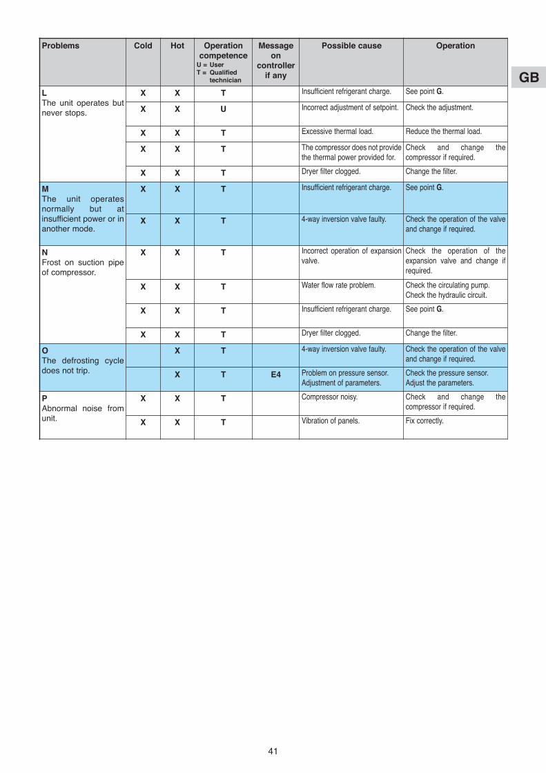
LThe unit operates butnever stops.
x x T Insufficient refrigerant charge. See point G.
x x u Incorrect adjustment of setpoint. Check the adjustment.
x x T Excessive thermal load. Reduce the thermal load.
x x T The compressor does not provide
the thermal power provided for.
Check and change the
compressor if required.
x x T Dryer filter clogged. Change the filter.
MThe unit operatesnormally but atinsufficient power or inanother mode.
x x T Insufficient refrigerant charge. See point G.
x x T 4-way inversion valve faulty. Check the operation of the valve
and change if required.
NFrost on suction pipeof compressor.
x x T Incorrect operation of expansion
valve.
Check the operation of the
expansion valve and change if
required.
x x T Water flow rate problem. Check the circulating pump.
Check the hydraulic circuit.
x x T Insufficient refrigerant charge. See point G.
x x T Dryer filter clogged. Change the filter.
oThe defrosting cycledoes not trip.
x T 4-way inversion valve faulty. Check the operation of the valve
and change if required.
x T E4 Problem on pressure sensor.
Adjustment of parameters.
Check the pressure sensor.
Adjust the parameters.
PAbnormal noise fromunit.
x x T Compressor noisy. Check and change the
compressor if required.
x x T Vibration of panels. Fix correctly.

GB
42
17 - START-uP DATA SHEET
CHGF / PHRF
Code:
Serial Number:
Started by: Company: Site: Date:
Voltage measured on unit V L1-L2 L2-L3 L3-L1
FAN 1
Measured amperage A/phase L1 L2 L3
FAN 2
Measured amperage A/phase L1 L2 L3
FAN 3
Measured amperage A/phase L1 L2 L3
FAN 4
Measured amperage A/phase L1 L2 L3
CoMPRESSoR 1
Measured amperage A/phase L1 L2 L3
CoMPRESSoR 2
Measured amperage A/phase L1 L2 L3
PuMP
Amperage A/phase L1 L2 L3
Circuit breaker thermal setting A
SENSoRS
Water temperature setpoint Cooling: Heating:
Water temperature control sensor positioned in: Inlet Outlet
TEMPERATuRES (°C) / PRESSuRES (bar)
Outside temperature
Water type Pure Glycol % Glycol
Water inlet, generator
Water outlet, generator
Water circuit pressure
Water flow rate
∆ T:
Suction, compressor
Discharge, compressor
Inlet, thermostatic expansion valve
Outlet, thermostatic expansion valve
Condensing pressure
Evaporating pressure
Superheating = (Compressor suction temperature - Evaporating temperature) = 7 to 8°C
Sub-cooling = (Condensating temperature - Expansion valve inlet temperature) = 3 to 5°C

GB
43

F
GB
D
I
E
22
F
GB
D
I
E
REMARQUE : Ce symbole et ce système de recyclage s'appliquent uniquement aux pays del’UE. Ils ne s'appliquent pas aux pays des autres régions du monde.
NOTE: This symbol mark and recycle system are applied only to EU countries and not appliedto the countries in the other area of the world.
NOTA : Questo simbolo e il sistema di riciclaggio sono validi soltanto per i paesi dell’UnioneEuropea e non sono validi per i paesi nel resto del mondo.
NOTA : Este símbolo y el sistema de reciclaje solamente son para países de la UE y no son aplicables a países de otras áreas del mundo.
HINWEIS : Dieses Symbol und Recycle-System gelten nur für Länder der Europäischen Union,nicht für andere Länder der Welt.
F
GB
I
E
D
Votre produit est conçu et fabriqué avec des matériels et des composants de qualité supérieure qui peuvent être recyclés etréutilisés.En fin de vie, il doit être éliminé séparément des ordures ménagères.Nous vous prions donc de confier cet équipement à votre centre local de collecte/recyclage.Dans l’Union Européenne, il existe des systèmes sélectifs de collecte pour les produits électriques et électroniques usagés.Aidez-nous à conserver l’environnement dans lequel nous vivons !Les appareils contiennent fréquemment des matières qui, si elles sont traitées ou éliminées de manière inapropriées, peuvents’avérer potentiellement dangereuses pour la santé humaine et pour l’environnement.Cependant, ces matières sont nécessaires au bon fonctionnement de votre appareil ou de votre machine. Pour cette raison, ilvous est demandé de ne pas vous débarrasser de votre appareil ou machine usagé avec vos ordures ménagères.
Your product is designed and manufactured with high quality materials and components which can be recycled and reused.At end of livetime, it should be eliminated separately from your household waste.Please dispose of this equipment at your local community waste collection/recycling centre.In the European Union there are separate collection systems for used electrical and electronic products.Please help us to conserve the environment we live in!Some equipments contain substances that are considered dangerous to the environment and human health if they are dispo-sed of carelessly.These substances, however, are required for your apparatus or machine to work properly. For this reason, it is requested thatit not be disposed of with other household waste at the end of its service life.
Il vostro prodotto è stato costruito da materiali e componenti di alta qualità, che sono riutilizzabili o riciclabili.Alla fine della sua vita utile deve essere smaltito separatamente dai rifiuti domestici.Vi preghiamo di smaltire questo apparecchio in un centro di raccolta differenziata locale.Nell'Unione Europea esistono sistemi di raccolta differenziata per prodotti elettrici ed elettronici.Aiutateci a conservare l'ambiente in cui viviamo!Gli apparecchi contengono spesso dei materiali che, se trattati od eliminati in modo non adeguato, possono dimostrarsi poten-zialmente pericolosi per la salute umana e per l'ambiente.Tuttavia, questi materiali sono necessari per il corretto funzionamento del vostro apparecchio o della vostra macchina. Per que-sto motivo, si richiede di non eliminare il proprio apparecchio o macchina usata assieme ai rifiuti domestici comuni.
Los productos están diseñados y fabricados con materiales y componentes de alta calidad, que pueden ser reciclados y reu-tilizados.Al final de su ciclo de vida, no se debe desechar con el resto de residuos domésticos. Por favor, deposite su viejo aparato enel punto de recogida de residuos o contacte con su administración local.En la Unión Europea existen sistemas de recogida específicos para residuos de aparatos eléctricos y electrónicos.Por favor, ayúdenos a conservar el medio ambiente!Los aparatos a menudo contienen materiales que, si son tratados o eliminados de forma inadecuada, pueden convertirse enpotencialmente peligrosos para la salud humana y para el medio ambiente.No obstante, estos materiales son necesarios para el buen funcionamiento de su máquina. Por esta razón, le rogamos enca-recidamente que al final de la vida útil de su aparato, no lo tire junto con la basura doméstica, sino que lo recicle adecuada-mente.
Ihr Produkt wurde entworfen und hergestellt mit qualitativ hochwertigen Materialien und Komponenten, die recycelt und wiederverwendet werden können.Am Ende ihrer Nutzungsdauer muss er getrennt vom Hausmüll eliminier werden sollen.Bitte entsorgen Sie dieses Gerät bei Ihrer örtlichen kommunalen Sammelstelle oder im Recycling Centre.In der Europäischen Union gibt es unterschiedliche Sammelsysteme für Elektrik- und Elektronikgeräte.Helfen Sie uns bitte, die Umwelt zu erhalten, in der wir leben!Die Geräte enthalten häufig Bestandteile aus bestimmten Werkstoffen, die bei einer nicht ordnungsgemäßen Behandlung oderEntsorgung eine Belastung für die menschliche Gesundheit und Umwelt darstellen.Diese Werkstoffe sind jedoch für die korrekte Funktionsweise Ihres Gerätes oder Maschine notwendig. Daher bitten wir Sie,Ihr(e) ausgediente(s) Gerät/Maschine nicht in den Hausmüll zu geben.
F
GB
I
E
D
F
GB
D
I
E
Par souci d'amélioration constante, nos produits peuvent être modifiés sans préavis.Due to our policy of continuous development, our products are liable to modification without notice.
Per garantire un costante miglioramento dei nostri prodotti, ci riserviamo di modificarli senza preaviso.En el interés de mejoras constantes, nuestros productos pueden modificarse sin aviso prévio.
Unsere Produkte werden laufend verbessert und können ohne Vorankündigung abgeändert werden.
Z.I. Route départementale 28CS 40131 Reyrieux01601 TRéVoUx Cedex FRANCETél. 04 74 00 92 92 - Fax 04 74 00 42 00Tel. 33 4 74 00 92 92 - Fax 33 4 74 00 42 00R.C.S. Bourg-en-Bresse B 759 200 728