Embed Size (px)
Citation preview
PHY 202 (Blum) 1
Inductors and Tuners
PHY 202 (Blum) 2
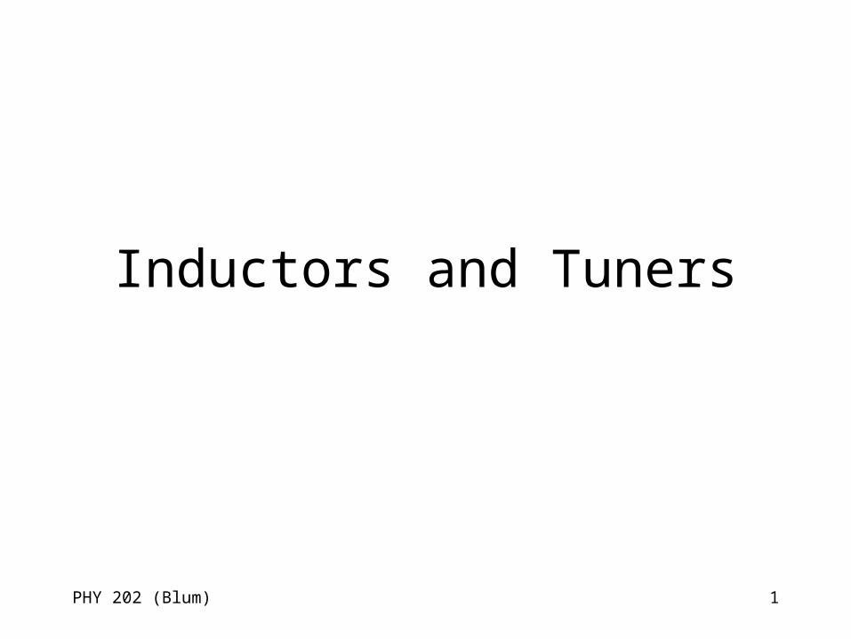
Currents lead to magnetic fields
• One law of physics states that an electric current gives rise to (is the source of) a magnetic field. – There are various versions of this law
associated with the following people• André-Marie Ampère
• Jean-Baptiste Biot and Felix Savart
• James Clerk Maxwell
PHY 202 (Blum) 3
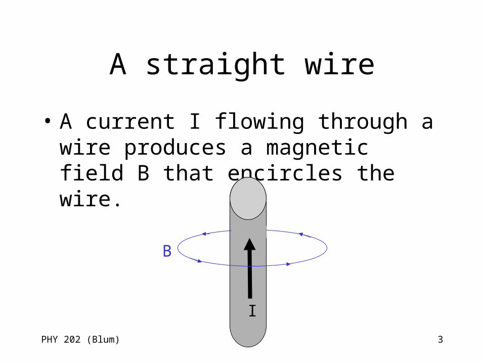
A straight wire
• A current I flowing through a wire produces a magnetic field B that encircles the wire.
I
B
PHY 202 (Blum) 4
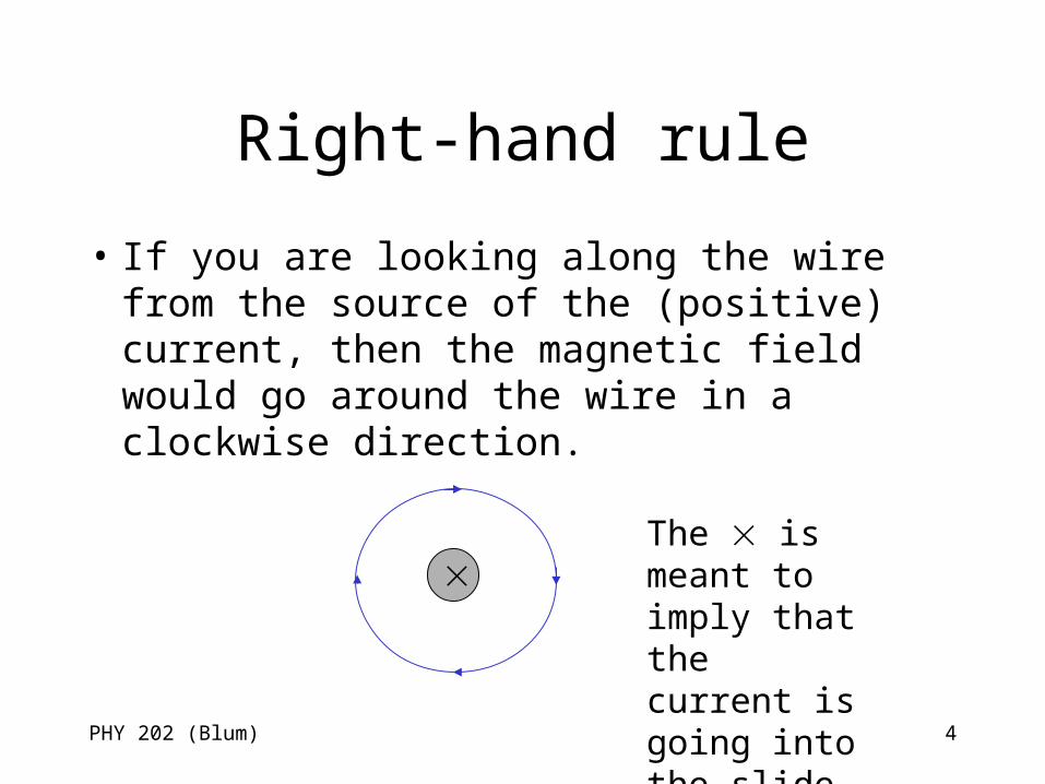
Right-hand rule
• If you are looking along the wire from the source of the (positive) current, then the magnetic field would go around the wire in a clockwise direction.
The is meant to imply that the current is going into the slide.
PHY 202 (Blum) 5
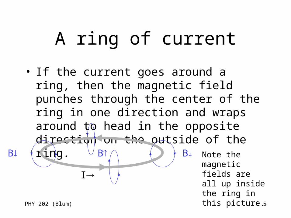
A ring of current
• If the current goes around a ring, then the magnetic field punches through the center of the ring in one direction and wraps around to head in the opposite direction on the outside of the ring.
I
BB B Note the magnetic fields are all up inside the ring in this picture.
PHY 202 (Blum) 6
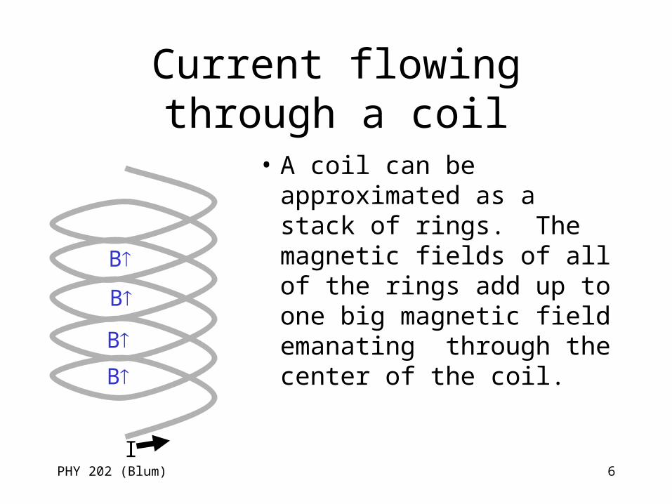
Current flowing through a coil
• A coil can be approximated as a stack of rings. The magnetic fields of all of the rings add up to one big magnetic field emanating through the center of the coil.
I
B
B
B
B
PHY 202 (Blum) 7
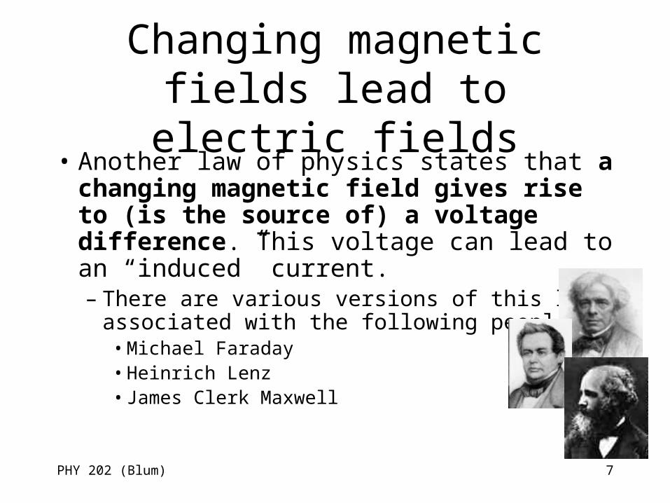
Changing magnetic fields lead to electric fields
• Another law of physics states that a changing magnetic field gives rise to (is the source of) a voltage difference. This voltage can lead to an “induced” current. – There are various versions of this law
associated with the following people• Michael Faraday• Heinrich Lenz• James Clerk Maxwell
PHY 202 (Blum) 8
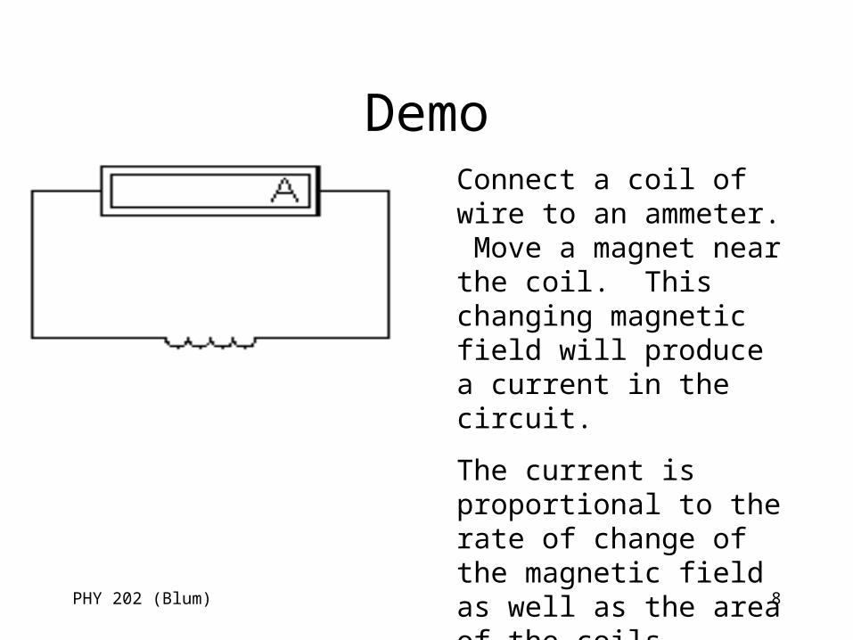
DemoConnect a coil of wire to an ammeter. Move a magnet near the coil. This changing magnetic field will produce a current in the circuit.
The current is proportional to the rate of change of the magnetic field as well as the area of the coils – think of as the area of a loop times the number of loops.
PHY 202 (Blum) 9
Why UTP is twisted
• UTP – unshielded twisted pair wire that is used for standard Ethernet connections twists the wires to have the opposite effect as our coil. Our coil has a large area, UTP is twisted to minimize the area and thus reduce any induced current due to magnetic fields in the environment.
PHY 202 (Blum) 10
Don’t go changing
• The current in our coil led to a magnetic field. • If the current changes then that magnetic field
changes, and that leads to a voltage. • That voltage leads to its own current in the coil. • That induced current opposes the change in the
current that caused. • Analogous to “inertia” objects in motion tend to
remain in motion.
PHY 202 (Blum) 11
Reduce current flowing through a coil
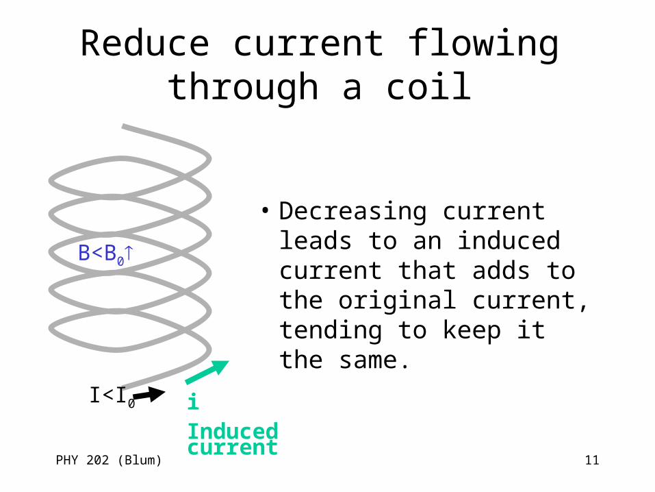
• Decreasing current leads to an induced current that adds to the original current, tending to keep it the same.
I<I0
B<B0
iInduced current
PHY 202 (Blum) 12
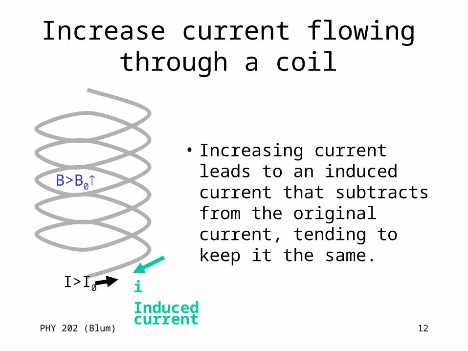
Increase current flowing through a coil
• Increasing current leads to an induced current that subtracts from the original current, tending to keep it the same.
I>I0
B>B0
iInduced current
PHY 202 (Blum) 13
Inductor
• A circuit element that opposes changes in the current is known as an inductor.
• They are also known as coils (since they tend to have that shape) and chokes.
• The units of inductance is the henry. – Named after Joseph Henry, an American scientist who
studied electricity and magnetism discovering a number of effects independent of Michael Faraday. Joseph Henry was also the first Secretary (director) of the Smithsonian Institution.
PHY 202 (Blum) 14
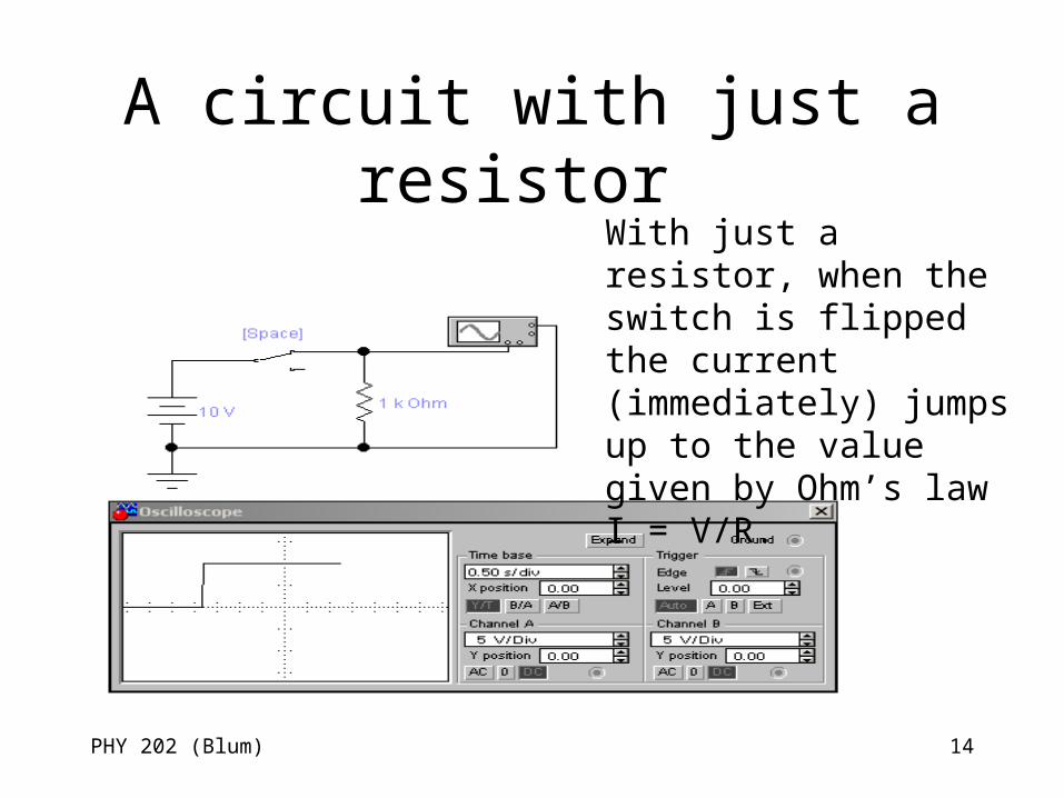
A circuit with just a resistor With just a resistor, when the switch is flipped the current (immediately) jumps up to the value given by Ohm’s law I = V/R.
PHY 202 (Blum) 15
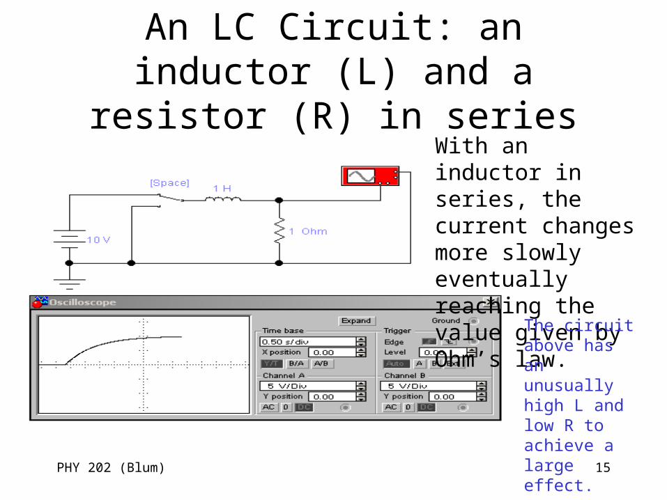
An LC Circuit: an inductor (L) and a resistor (R) in series
With an inductor in series, the current changes more slowly eventually reaching the value given by Ohm’s law.
The circuit above has an unusually high L and low R to achieve a large effect.
PHY 202 (Blum) 16
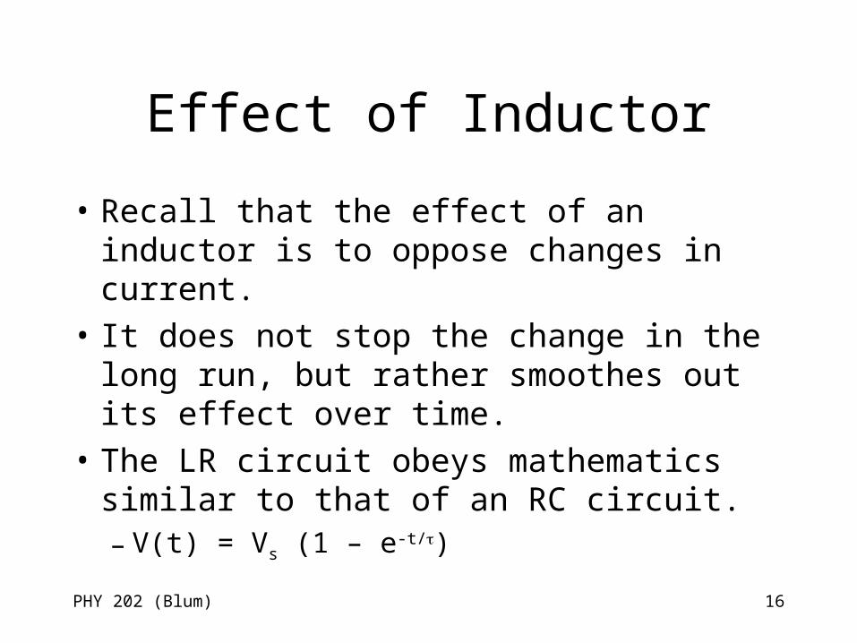
Effect of Inductor
• Recall that the effect of an inductor is to oppose changes in current.
• It does not stop the change in the long run, but rather smoothes out its effect over time.
• The LR circuit obeys mathematics similar to that of an RC circuit. – V(t) = Vs (1 – e-t/)

PHY 202 (Blum) 17
Also slows down the decrease in current
V(t) = V0 e –t/
PHY 202 (Blum) 18
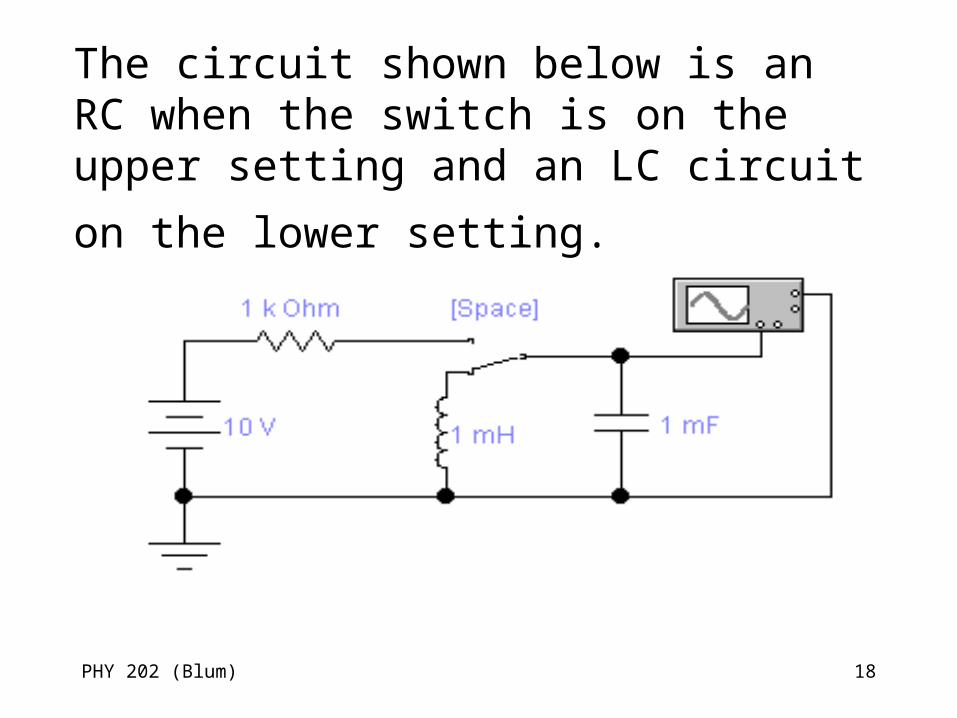
The circuit shown below is an RC when the switch is on the upper setting and an LC
circuit on the lower setting.
PHY 202 (Blum) 19
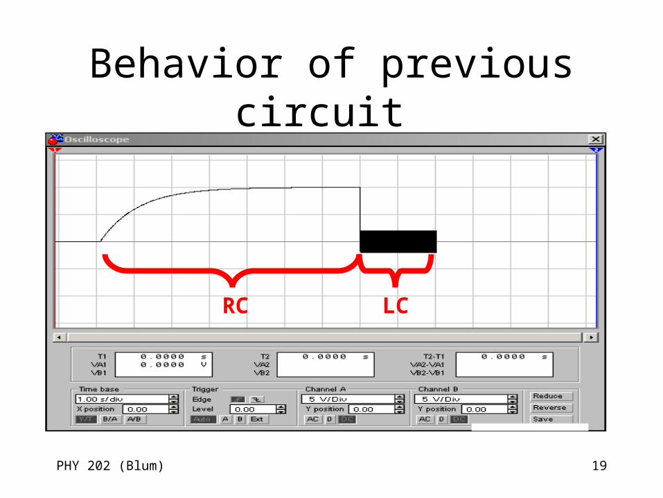
Behavior of previous circuit
RC LC
PHY 202 (Blum) 20
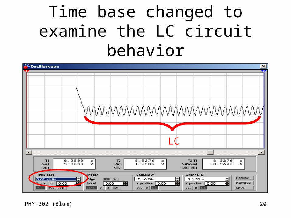
Time base changed to examine the LC circuit behavior
LC
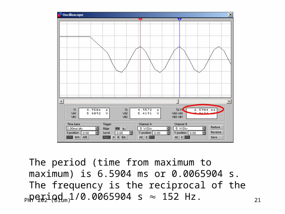
PHY 202 (Blum) 21
The period (time from maximum to maximum) is 6.5904 ms or 0.0065904 s. The frequency is the reciprocal of the period 1/0.0065904 s 152 Hz.
PHY 202 (Blum) 22
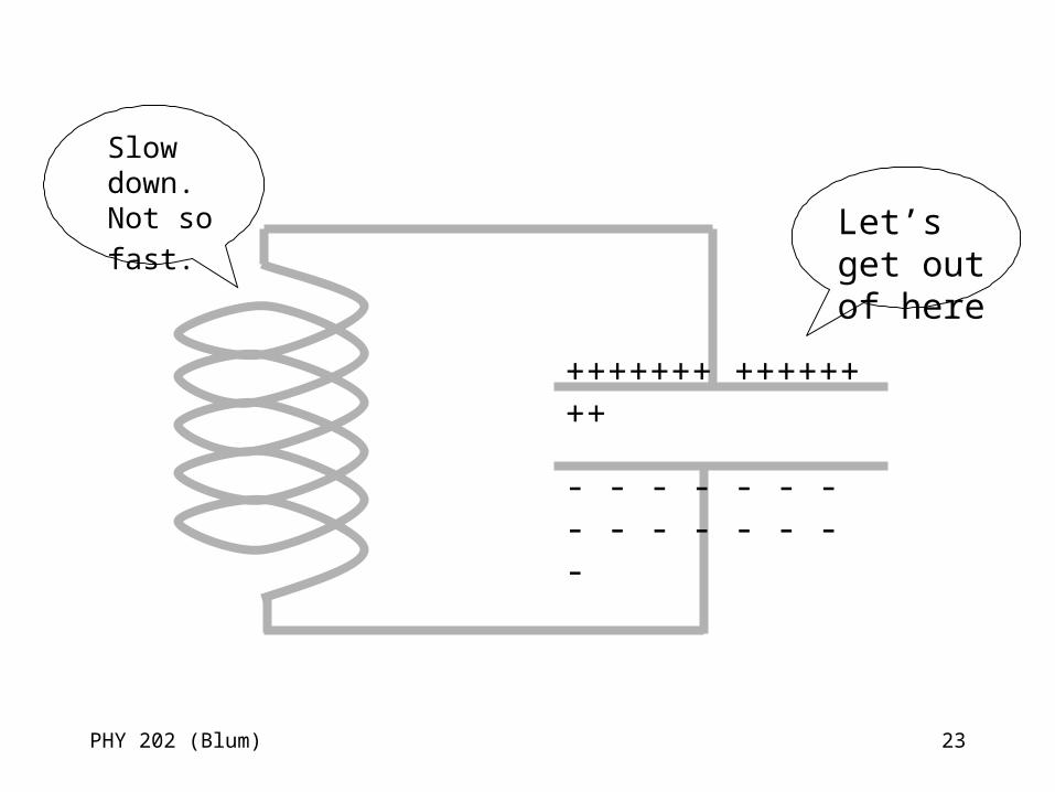
Periodic Behavior of LC Circuit
• The charged capacitor wants to get rid of its charge (i.e. to get the charge on the positive plate to travel around and meet up with the negative charge or vice versa).
• To do this, there must be a current. • Since there was not previously a current,
the inductor will tend to keep the current from growing too quickly.
PHY 202 (Blum) 23
+++++++ ++++++++
- - - - - - - - - - - - - - -
Let’s get out of here
Slow down. Not
so fast.
PHY 202 (Blum) 24
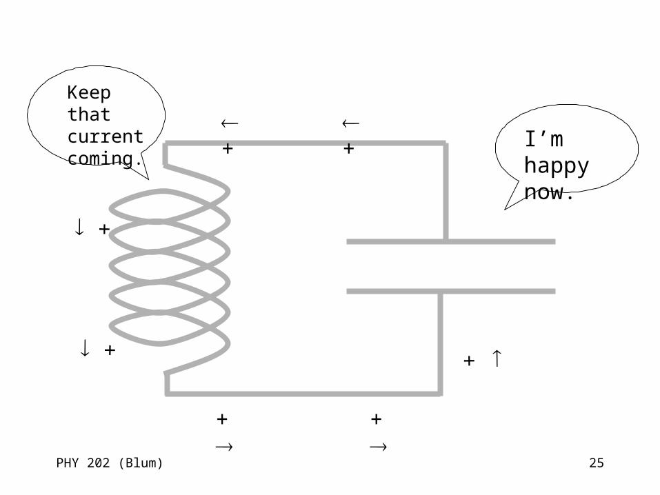
Periodic Behavior of LC Circuit (Cont.)
• The current ultimately gets established and the capacitor discharges.
• But the inductor will not let the current diminish very quickly.
• Thus the current continues and the capacitor begins to charge again. This time the plate that was positive now becomes negative.
• The current will diminish but it the time it takes the capacitor will again become charged.
PHY 202 (Blum) 25
I’m happy now.
Keep that current coming.
+ +
+
+
+ +
+
PHY 202 (Blum) 26
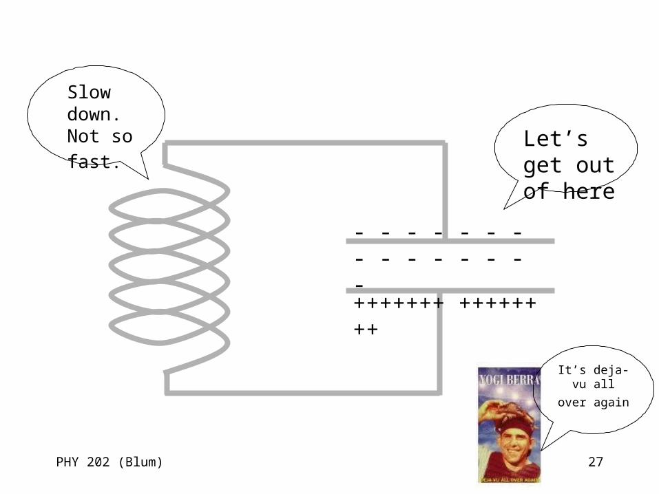
Periodic Behavior of LC Circuit (Cont.)
• Eventually we reach the same situation we started with – a charged capacitor and no current (just that the plates have the opposite charge from before) and the process starts over again.
• Another way to view the process is in terms of energy. The capacitor stores energy in an electric form and the inductor stores energy in a magnetic form. The energy switches back and forth between electric and magnetic.
PHY 202 (Blum) 27
- - - - - - - - - - - - - - -
+++++++ ++++++++
Let’s get out of here
Slow down. Not
so fast.
It’s deja-vu all over
again
PHY 202 (Blum) 28
Natural frequency
• The LC circuit has a periodic behavior. Period behavior is characterized by a frequency – the number of cycles exhibited per second (measured in Hertz).
• We call the frequency exhibited by the LC circuit by itself the LC circuit’s “natural frequency” to distinguish it from the “driving frequency” which we introduce next.
PHY 202 (Blum) 29
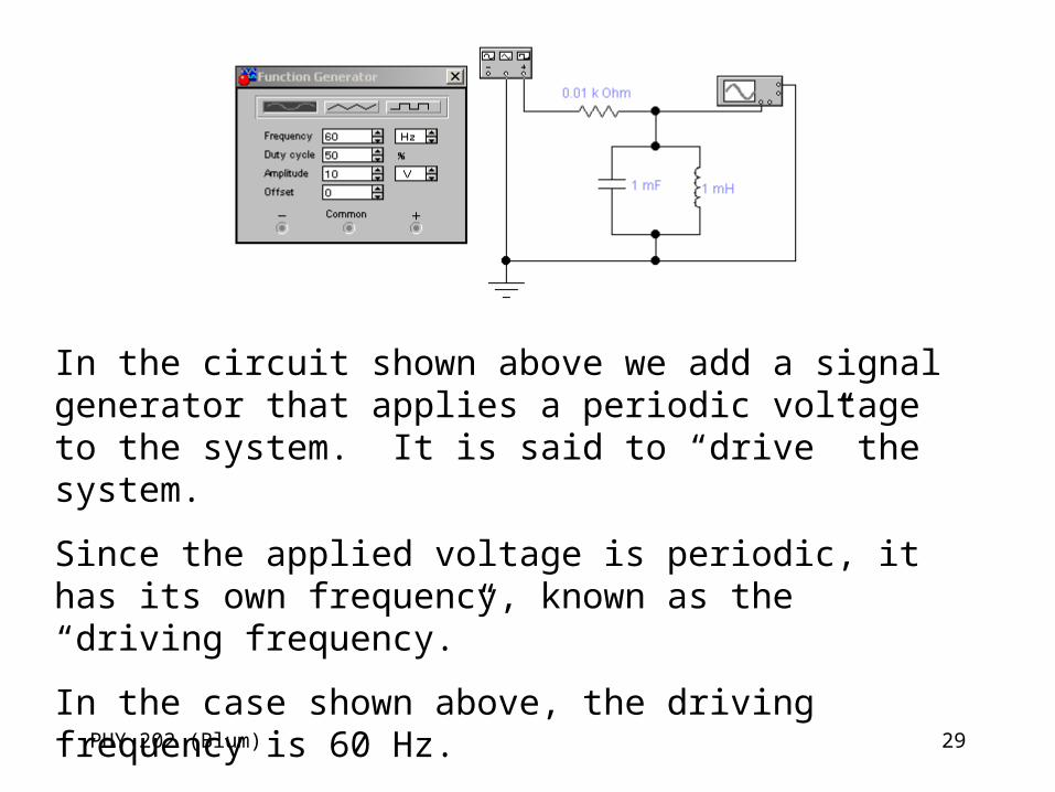
In the circuit shown above we add a signal generator that applies a periodic voltage to the system. It is said to “drive” the system.
Since the applied voltage is periodic, it has its own frequency, known as the “driving frequency.”
In the case shown above, the driving frequency is 60 Hz.
PHY 202 (Blum) 30
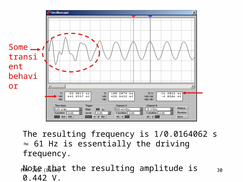
Some transient behavior
The resulting frequency is 1/0.0164062 s 61 Hz is essentially the driving frequency.
Note that the resulting amplitude is 0.442 V.
PHY 202 (Blum) 31
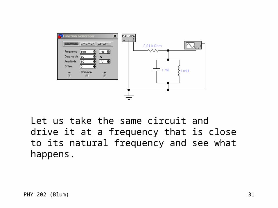
Let us take the same circuit and drive it at a frequency that is close to its natural frequency and see what happens.
PHY 202 (Blum) 32
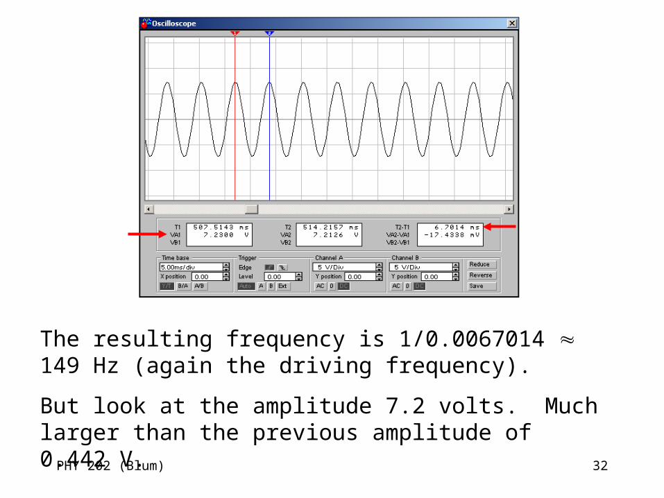
The resulting frequency is 1/0.0067014 149 Hz (again the driving frequency).
But look at the amplitude 7.2 volts. Much larger than the previous amplitude of 0.442 V.
PHY 202 (Blum) 33
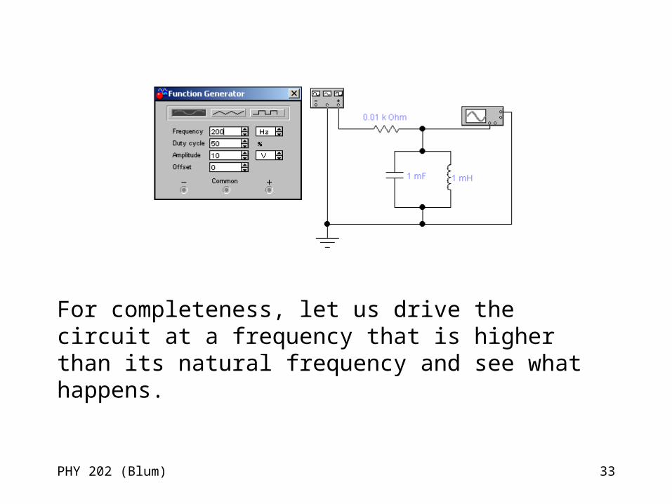
For completeness, let us drive the circuit at a frequency that is higher than its natural frequency and see what happens.
PHY 202 (Blum) 34
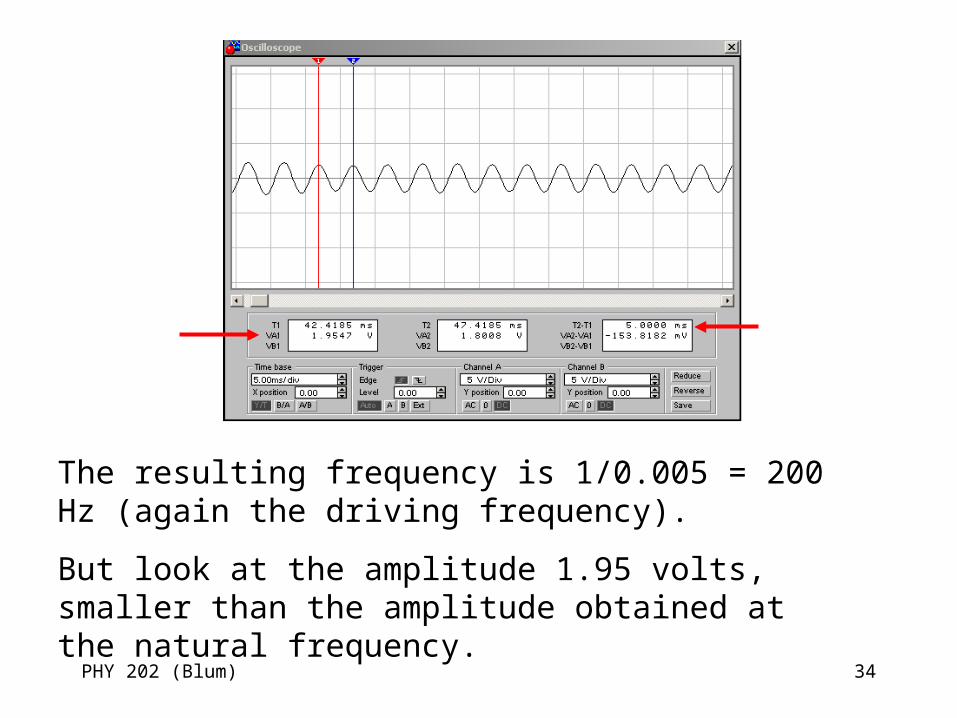
The resulting frequency is 1/0.005 = 200 Hz (again the driving frequency).
But look at the amplitude 1.95 volts, smaller than the amplitude obtained at the natural frequency.
PHY 202 (Blum) 35
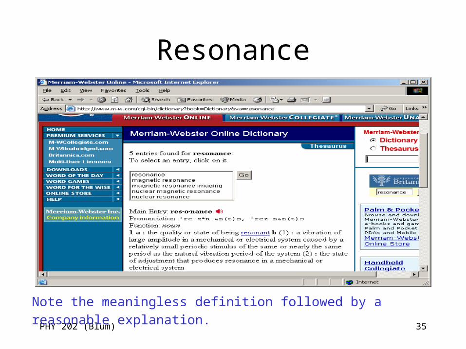
Resonance
Note the meaningless definition followed by a reasonable explanation.
PHY 202 (Blum) 36
Radio: Transmitter
• Now we are in a position to understand radio.
• In the transmitter a carrier signal (simple sine wave) is modulated (usually at a lower a frequency than the carrier.
• This modulated signal is amplified and fed into an antenna so that the transmitting antenna has a large varying current in it.
PHY 202 (Blum) 37
Radio: Wave• The varying current in the antenna produces a
varying magnetic field. • That varying magnetic field produces a varying
electric field. • That varying electric field produces a varying
magnetic field. • And so on. • This is an electromagnetic or radio wave
propagating through space and carrying our information away from the source/transmitter.
PHY 202 (Blum) 38
Radio: Receiver
• Our radio wave happens by an antenna. Because of the varying electric field, a current is established in our antenna.
• We are receiving/detecting the signal.• But lots of other people are sending signals and
we are receiving their signal as well. • Fortunately there is a large range of possible
carrier frequencies and we can use these to distinguish one signal from another.
PHY 202 (Blum) 39
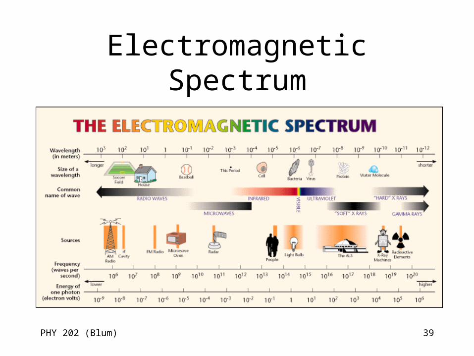
Electromagnetic Spectrum
PHY 202 (Blum) 40
Radio: Tuner
• Our LC circuit serves as a simple tuner. • Using the notion of resonance, we can pick out a
particular frequency by making an LC circuit with a natural frequency that matches the carrier frequency.
• Signals close to the natural frequency emerge from the LC tuner with a large amplitude, any signal much higher or lower in frequency is suppressed.
PHY 202 (Blum) 41
Radio: Filter/Demodulator
• Another step is required. The information must be stripped away from the carrier.
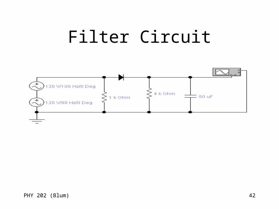
• We can use the time constant associated with an RC circuit here. The times faster than the time constant are smoothed over but times longer than the time constant remain.
PHY 202 (Blum) 42
Filter Circuit
PHY 202 (Blum) 43
Final Step
• The final step, now that we have the original (demodulated) signal is to amplify.
• Amplification uses transistors in the “transition” phase – between the on and off we usually use in logic circuitry.
PHY 202 (Blum) 44
References
• Electronics The Easy Way, Miller and Miller
• http://electronics.howstuffworks.com/inductor.htm/printable
• http://electronics.howstuffworks.com/oscillator.htm/printable
• http://electronics.howstuffworks.com/radio.htm/printable