Embed Size (px)
Citation preview
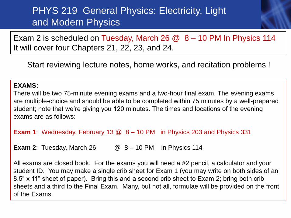
EXAMS:
There will be two 75-minute evening exams and a two-hour final exam. The evening exams
are multiple-choice and should be able to be completed within 75 minutes by a well-prepared
student; note that we’re giving you 120 minutes. The times and locations of the evening
exams are as follows:
Exam 1: Wednesday, February 13 @ 8 – 10 PM in Physics 203 and Physics 331
Exam 2: Tuesday, March 26 @ 8 – 10 PM in Physics 114
All exams are closed book. For the exams you will need a #2 pencil, a calculator and your
student ID. You may make a single crib sheet for Exam 1 (you may write on both sides of an
8.5” x 11” sheet of paper). Bring this and a second crib sheet to Exam 2; bring both crib
sheets and a third to the Final Exam. Many, but not all, formulae will be provided on the front
of the Exams.
PHYS 219 General Physics: Electricity, Light
and Modern Physics
Exam 2 is scheduled on Tuesday, March 26 @ 8 – 10 PM In Physics 114
It will cover four Chapters 21, 22, 23, and 24.
Start reviewing lecture notes, home works, and recitation problems !
Chapter 24 Geometrical Optics – Lecture 17
24.1 Ray (Geometrical) Optics
24.2 Reflection from a Plane Mirror
24.3 Refraction
24.4 Reflections and Images Produced by Curved Mirrors
24.5 Lenses
24.6 How the Eye Works
24.7 Optics in the Atmosphere
24.8 Aberrations
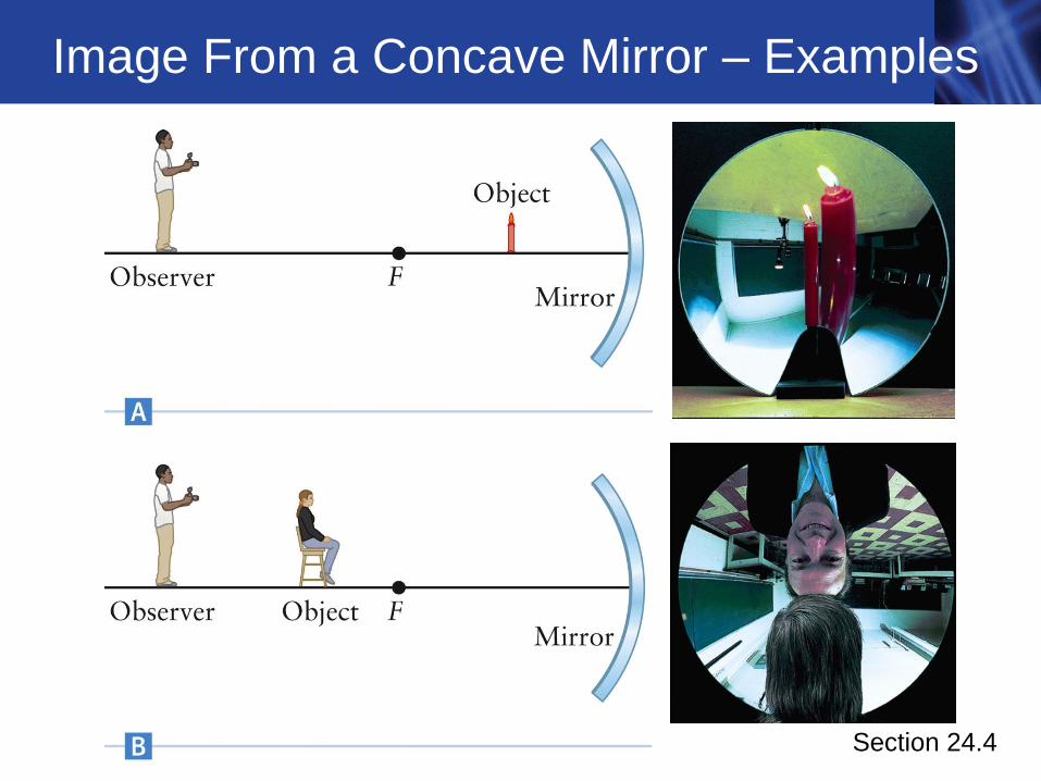
Image From a Concave Mirror – Examples
Section 24.4
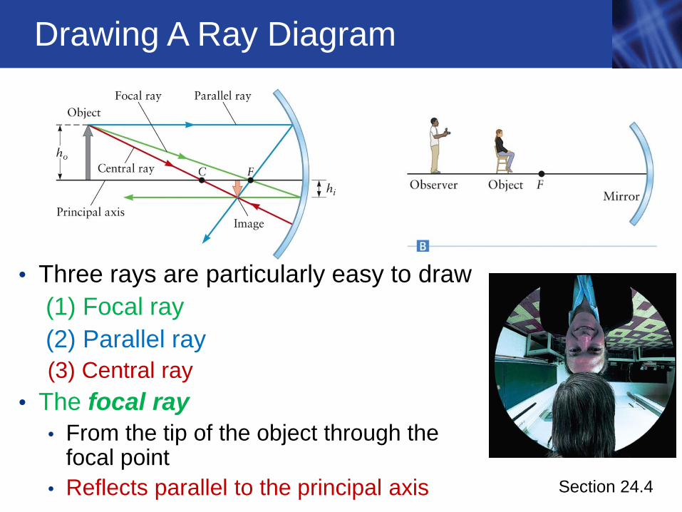
Drawing A Ray Diagram
• Three rays are particularly easy to draw
(1) Focal ray
(2) Parallel ray
(3) Central ray
• The focal ray
• From the tip of the object through the focal point
• Reflects parallel to the principal axis
Section 24.4
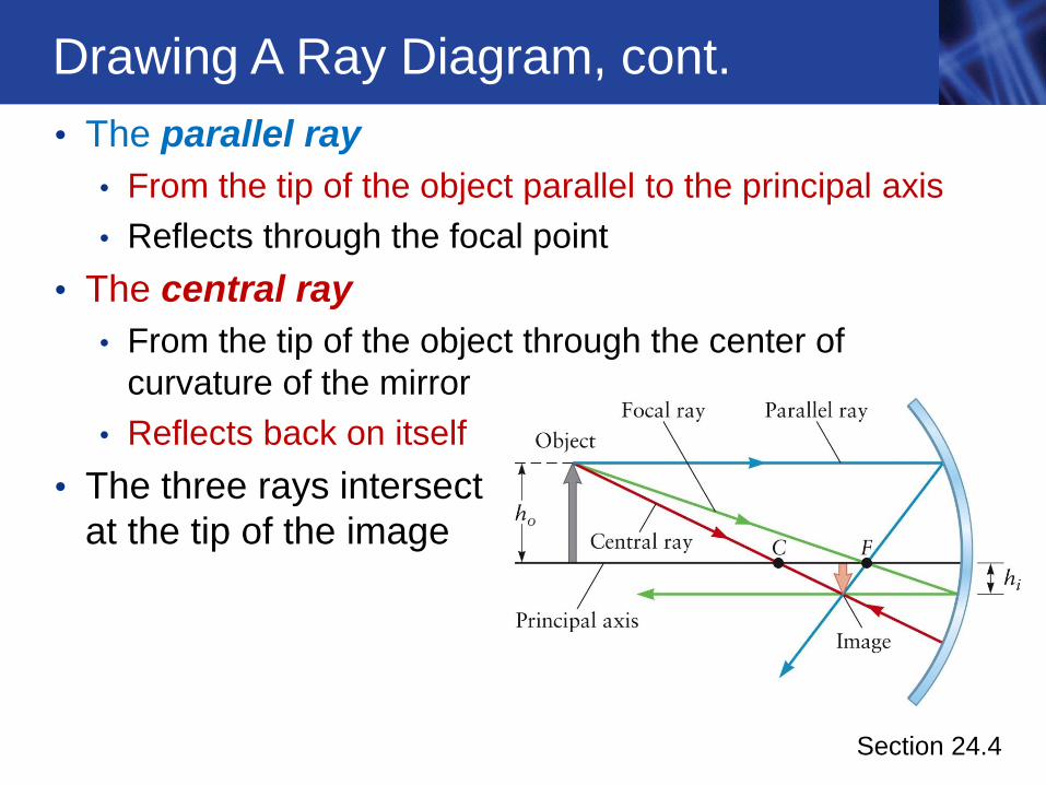
Drawing A Ray Diagram, cont.
• The parallel ray
• From the tip of the object parallel to the principal axis
• Reflects through the focal point
• The central ray
• From the tip of the object through the center of
curvature of the mirror
• Reflects back on itself
• The three rays intersect
at the tip of the image
Section 24.4
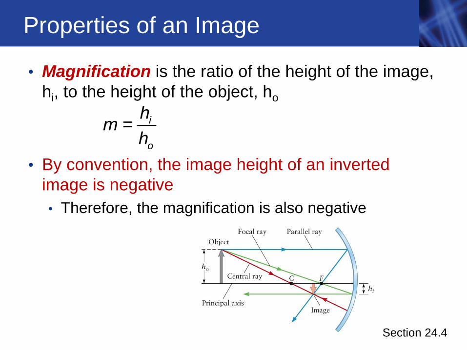
Properties of an Image
• Magnification is the ratio of the height of the image,
hi, to the height of the object, ho
• By convention, the image height of an inverted
image is negative
• Therefore, the magnification is also negative
Section 24.4
i
o
hm
h=
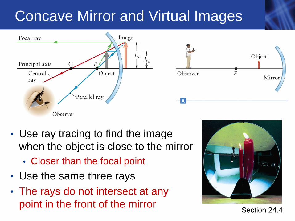
Concave Mirror and Virtual Images
• Use ray tracing to find the image
when the object is close to the mirror
• Closer than the focal point
• Use the same three rays
• The rays do not intersect at any
point in the front of the mirror Section 24.4
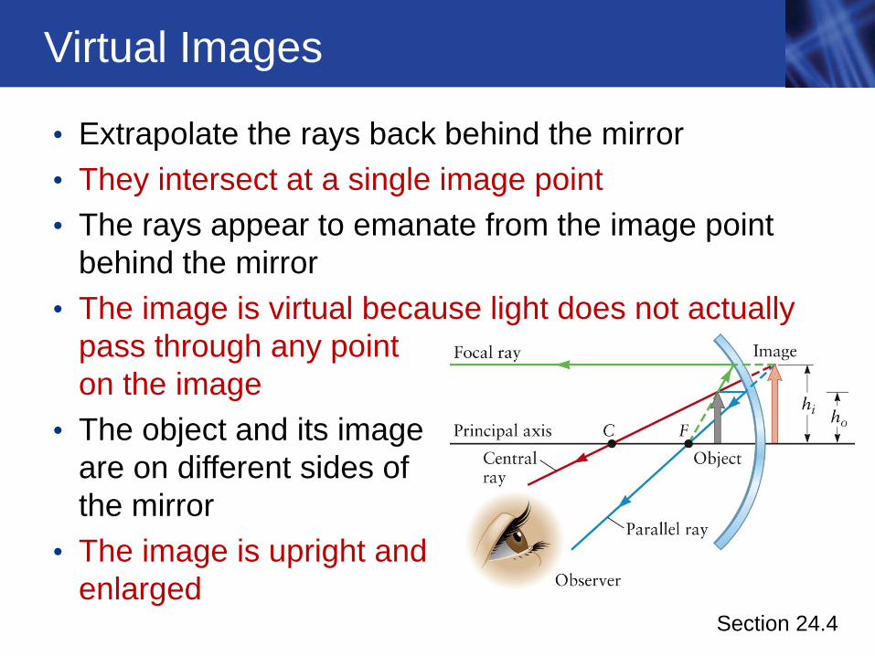
Virtual Images
• Extrapolate the rays back behind the mirror
• They intersect at a single image point
• The rays appear to emanate from the image point
behind the mirror
• The image is virtual because light does not actually
pass through any point
on the image
• The object and its image
are on different sides of
the mirror
• The image is upright and
enlarged Section 24.4
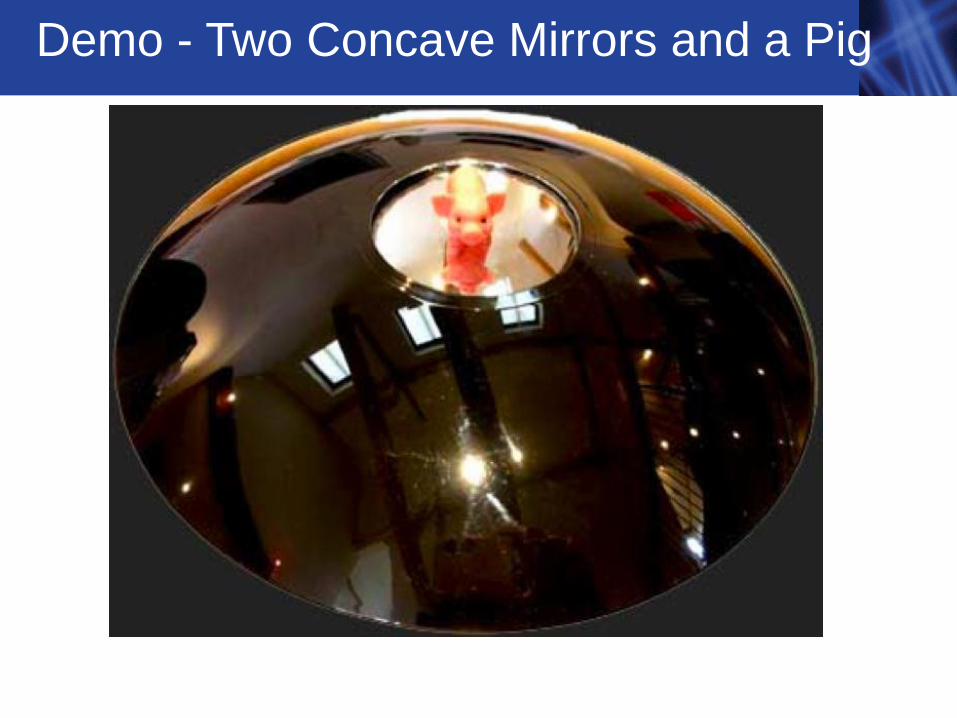
Demo - Two Concave Mirrors and a Pig
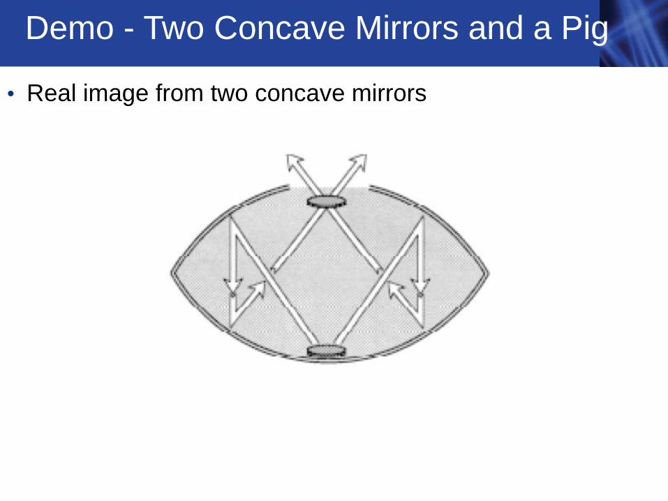
Demo - Two Concave Mirrors and a Pig
• Real image from two concave mirrors
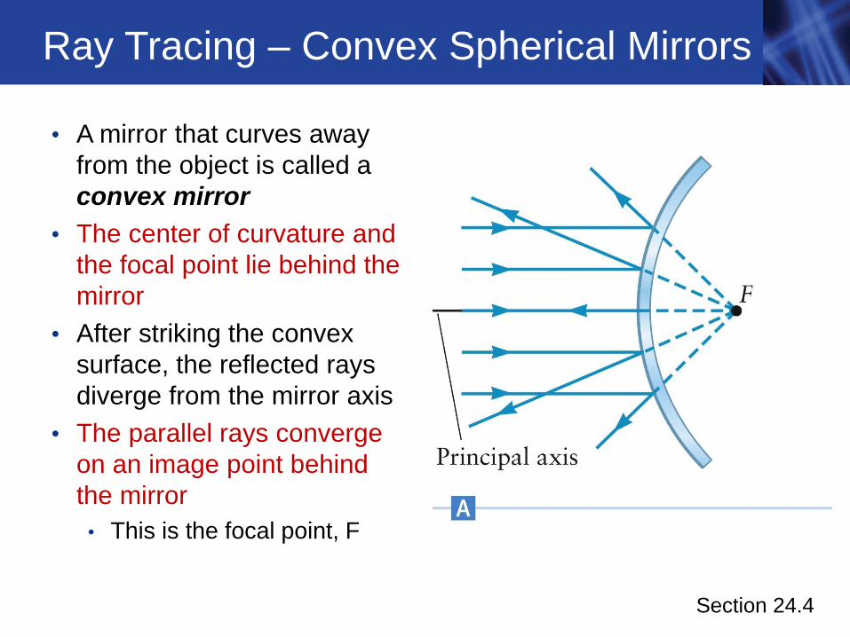
Ray Tracing – Convex Spherical Mirrors
• A mirror that curves away
from the object is called a
convex mirror
• The center of curvature and
the focal point lie behind the
mirror
• After striking the convex
surface, the reflected rays
diverge from the mirror axis
• The parallel rays converge
on an image point behind
the mirror
• This is the focal point, F
Section 24.4
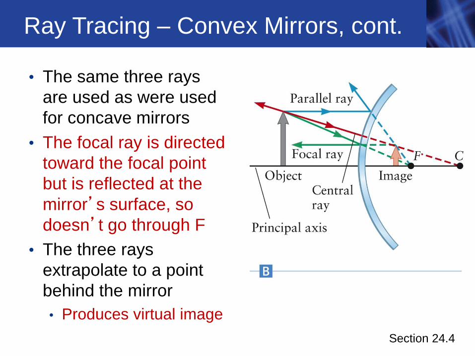
Ray Tracing – Convex Mirrors, cont.
• The same three rays
are used as were used
for concave mirrors
• The focal ray is directed
toward the focal point
but is reflected at the
mirror’s surface, so
doesn’t go through F
• The three rays
extrapolate to a point
behind the mirror
• Produces virtual image
Section 24.4
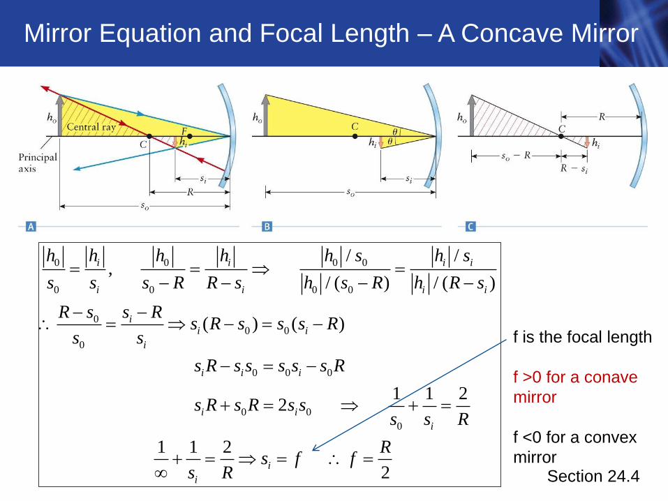
Mirror Equation and Focal Length – A Concave Mirror
Section 24.4
0 0 0 0
0 0 0 0
00 0
0
0 0 0
0 0
0
/ /,
/ ( ) / ( )
( ) ( )
1 1 22
1 1 2
2
i i i i
i i i i
ii i
i
i i i
i i
i
i
i
h h h h h s h s
s s s R R s h s R h R s
R s s Rs R s s s R
s s
s R s s s s s R
s R s R s ss s R
Rs f f
s R
f is the focal length
f >0 for a conave
mirror
f <0 for a convex
mirror
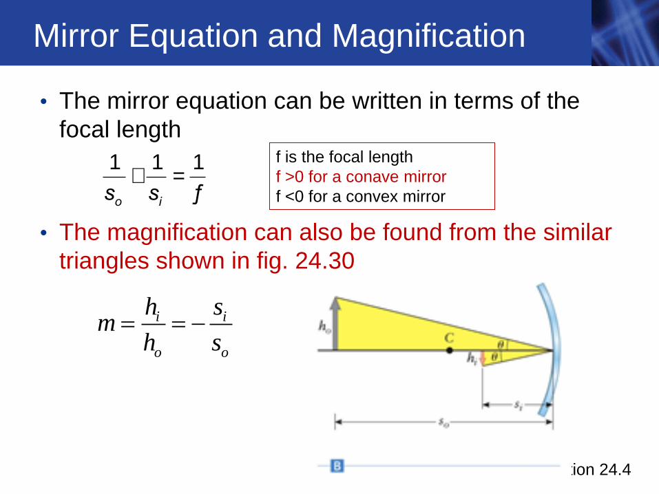
Mirror Equation and Magnification
• The mirror equation can be written in terms of the
focal length
• The magnification can also be found from the similar
triangles shown in fig. 24.30
o is s+ =
1 1 1
ƒ
Section 24.4
f is the focal length
f >0 for a conave mirror
f <0 for a convex mirror
i i
o o
h sm
h s
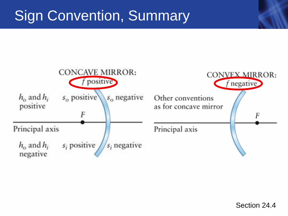
Sign Convention, Summary
Section 24.4
Lenses
• A lens uses refraction to form an image
• Typical lenses are composed of glass or plastic
• The refraction of the light rays as they pass from the
air into the lens and then back into the air causes the
rays to be redirected
• Although refraction occurs at both surfaces of the lens,
for simplicity the rays are drawn to the center of the
lens
Section 24.5
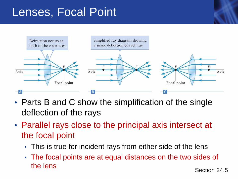
Lenses, Focal Point
• Parts B and C show the simplification of the single
deflection of the rays
• Parallel rays close to the principal axis intersect at
the focal point
• This is true for incident rays from either side of the lens
• The focal points are at equal distances on the two sides of
the lens
Section 24.5
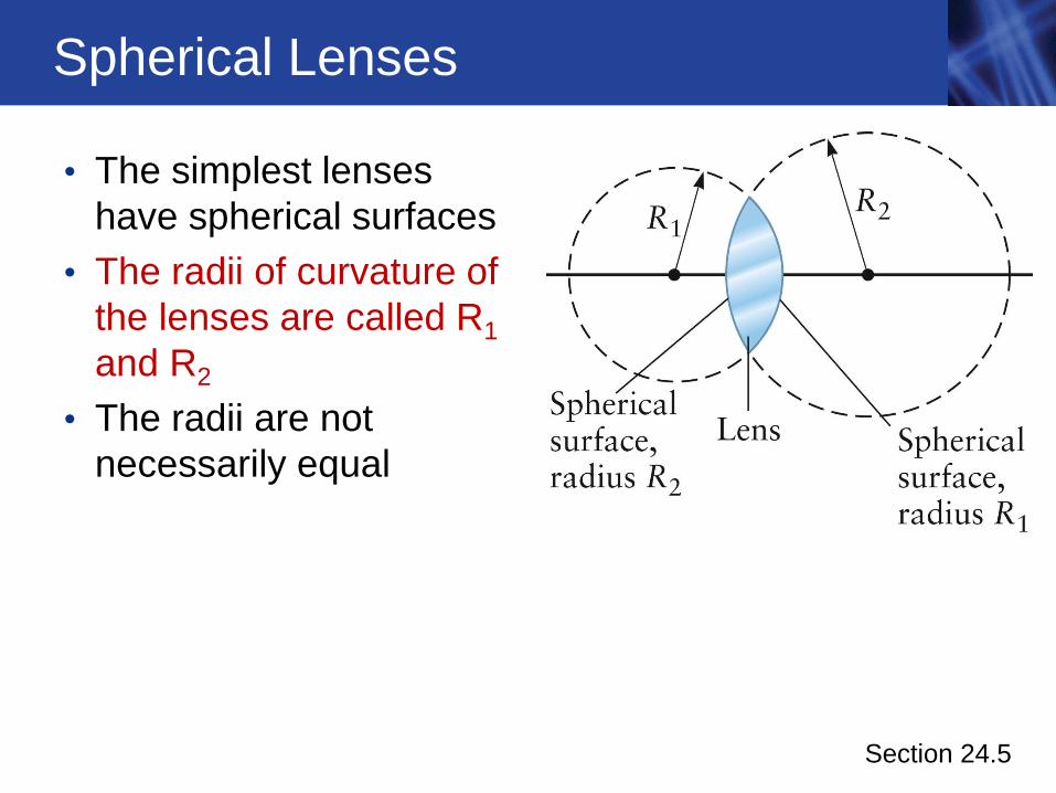
Spherical Lenses
• The simplest lenses
have spherical surfaces
• The radii of curvature of
the lenses are called R1
and R2
• The radii are not
necessarily equal
Section 24.5
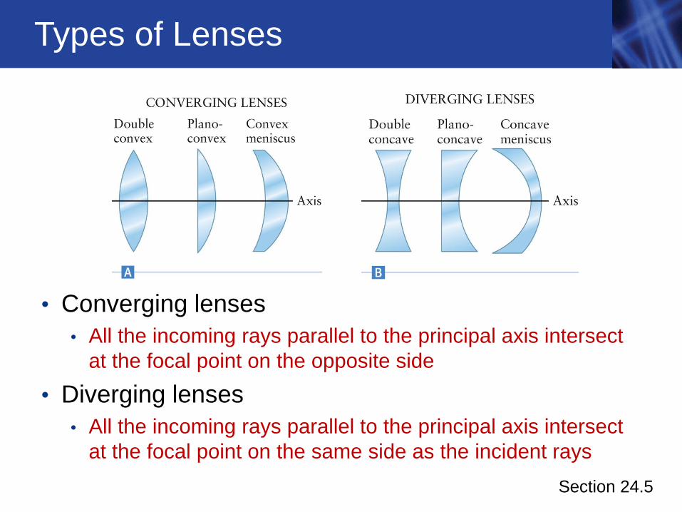
Types of Lenses
• Converging lenses
• All the incoming rays parallel to the principal axis intersect
at the focal point on the opposite side
• Diverging lenses
• All the incoming rays parallel to the principal axis intersect
at the focal point on the same side as the incident rays
Section 24.5
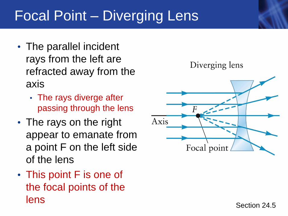
Focal Point – Diverging Lens
• The parallel incident
rays from the left are
refracted away from the
axis
• The rays diverge after
passing through the lens
• The rays on the right
appear to emanate from
a point F on the left side
of the lens
• This point F is one of
the focal points of the
lens Section 24.5
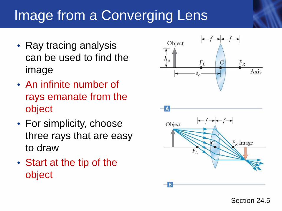
Image from a Converging Lens
• Ray tracing analysis
can be used to find the
image
• An infinite number of
rays emanate from the
object
• For simplicity, choose
three rays that are easy
to draw
• Start at the tip of the
object
Section 24.5
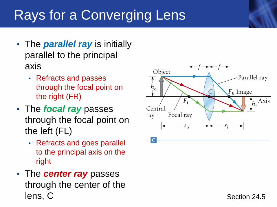
Rays for a Converging Lens
• The parallel ray is initially
parallel to the principal
axis
• Refracts and passes
through the focal point on
the right (FR)
• The focal ray passes
through the focal point on
the left (FL)
• Refracts and goes parallel
to the principal axis on the
right
• The center ray passes
through the center of the
lens, C Section 24.5
Rays, cont.
• If the lens is very thin, the center ray is not deflected
by the lens
• These three rays come together at the tip of the
image on the right of the lens
• In this case, the image is inverted
• The image is real
• The rays pass through the image
Section 24.5
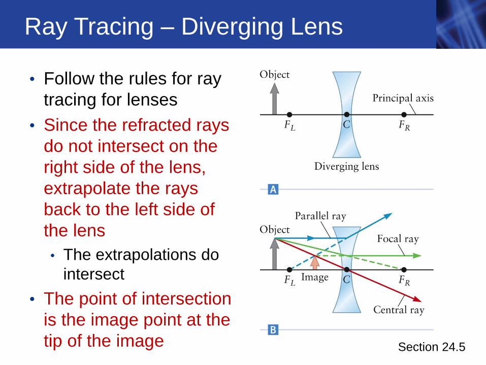
Ray Tracing – Diverging Lens
• Follow the rules for ray
tracing for lenses
• Since the refracted rays
do not intersect on the
right side of the lens,
extrapolate the rays
back to the left side of
the lens
• The extrapolations do
intersect
• The point of intersection
is the image point at the
tip of the image Section 24.5
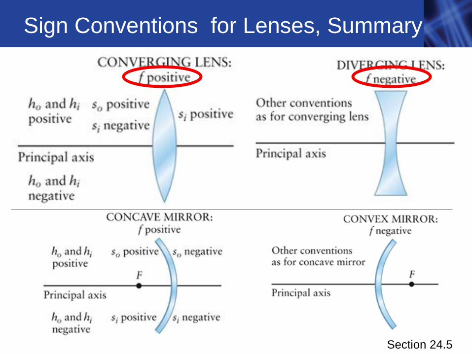
Sign Conventions for Lenses, Summary
Section 24.5
/ /,
/ / ( )
( )
1 1 1
o i o i o o i i
o i i o i i
ii o i
o i
i o o i
o i
h h h h h s h s
s s f s f h f h s f
s ffor s f s s f
s s
or s f s f s ss s f
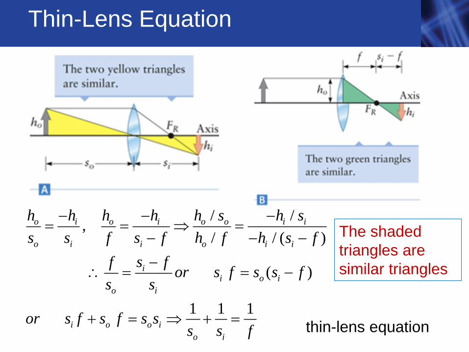
Thin-Lens Equation
thin-lens equation
The shaded
triangles are
similar triangles
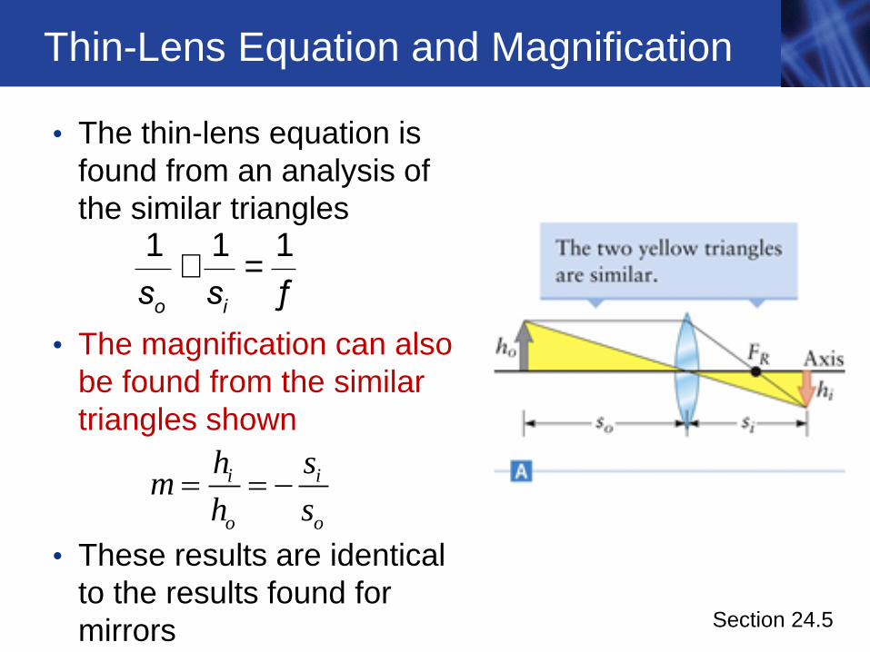
Thin-Lens Equation and Magnification
• The thin-lens equation is
found from an analysis of
the similar triangles
• The magnification can also
be found from the similar
triangles shown
• These results are identical
to the results found for
mirrors
o is s+ =
1 1 1
ƒ
Section 24.5
i i
o o
h sm
h s
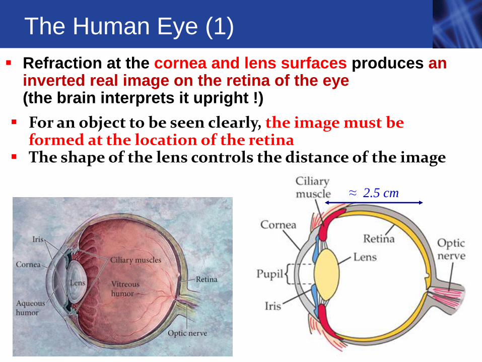
The Human Eye (1)
≈ 2.5 cm
Refraction at the cornea and lens surfaces produces an inverted real image on the retina of the eye (the brain interprets it upright !)
For an object to be seen clearly, the image must be formed at the location of the retina
The shape of the lens controls the distance of the image
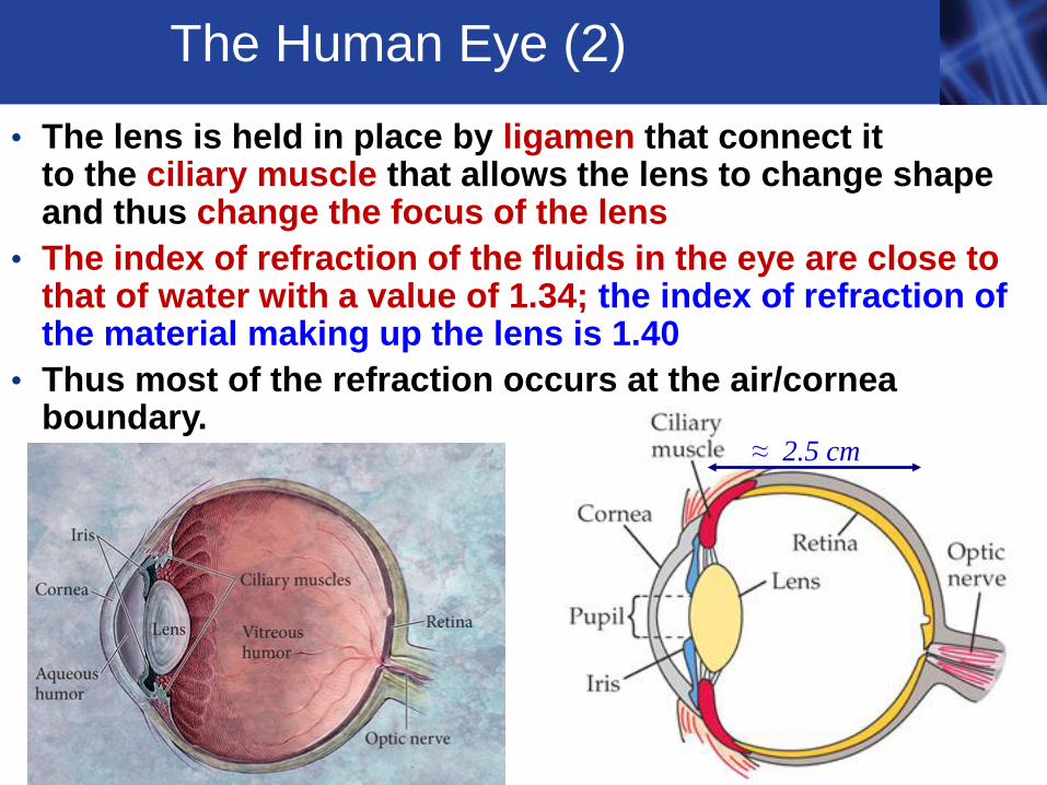
• The lens is held in place by ligamen that connect it to the ciliary muscle that allows the lens to change shape and thus change the focus of the lens
• The index of refraction of the fluids in the eye are close to that of water with a value of 1.34; the index of refraction of the material making up the lens is 1.40
• Thus most of the refraction occurs at the air/cornea boundary.
The Human Eye (2)
≈ 2.5 cm
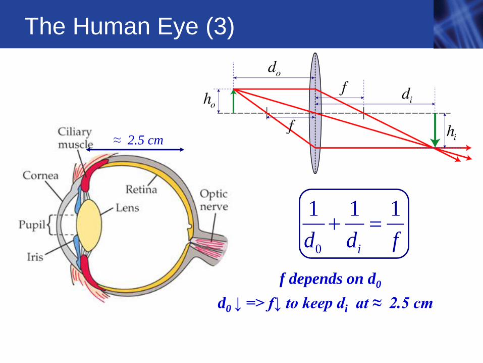
The Human Eye (3)
≈ 2.5 cm
0
1 1 1
id d f
f depends on d0
d0 ↓ => f↓ to keep di at ≈ 2.5 cm
Example: Corrective Lenses (1)
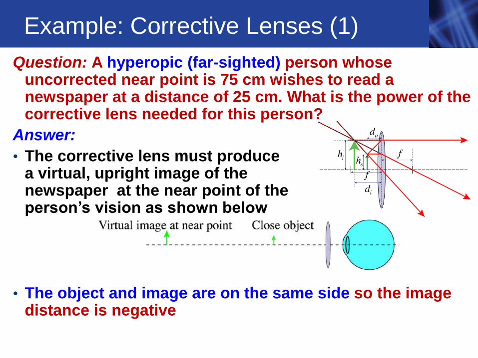
Question: A hyperopic (far-sighted) person whose uncorrected near point is 75 cm wishes to read a newspaper at a distance of 25 cm. What is the power of the corrective lens needed for this person?
Answer:
• The corrective lens must produce a virtual, upright image of the newspaper at the near point of the person’s vision as shown below
• The object and image are on the same side so the image distance is negative
Example: Corrective Lenses (2)
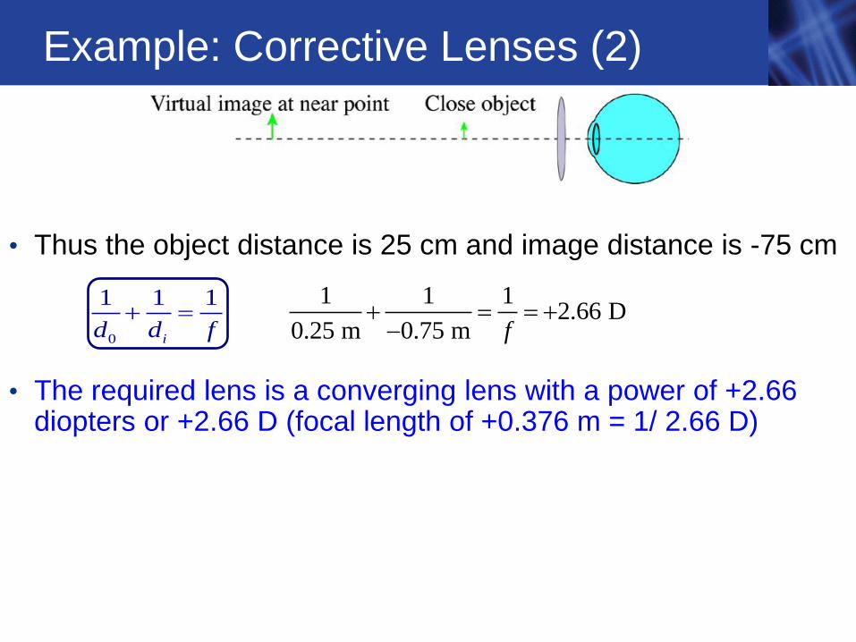
• Thus the object distance is 25 cm and image distance is -75 cm
• The required lens is a converging lens with a power of +2.66 diopters or +2.66 D (focal length of +0.376 m = 1/ 2.66 D)
1 1 12.66 D
0.25 m 0.75 m f 0
1 1 1
id d f
Demos
Coin Illusion 7A-11
Images formed by Lenses 7A-30
Eye Model 7A-33


![Cost-Optimal ATCs in Zonal Electricity Markets · across borders and integrating more renewables, drives the coupling of the European electricity system [13]. The phys-ical system](https://img.pdfslide.net/doc/110x75/5ecb084ddb57f746241d88e3/cost-optimal-atcs-in-zonal-electricity-markets-across-borders-and-integrating-more.jpg)