Embed Size (px)
Citation preview
1
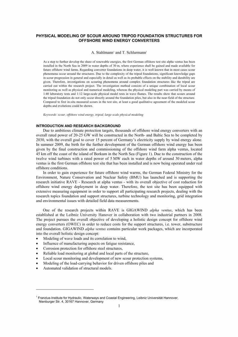
PHYSICAL MODELING OF SCOUR AROUND TRIPOD FOUNDATION STRUCTURES FOR OFFSHORE WIND ENERGY CONVERTERS
A. Stahlmann1 and T. Schlurmann1
As a step to further develop the share of renewable energies, the first German offshore test site alpha ventus has been installed in the North Sea in 2009 in water depths of 30 m, where experience shall be gained and made available for future offshore wind farms. Regarding converter foundations in deep water, it is well known that in most cases scour phenomena occur around the structures. Due to the complexity of the tripod foundations, significant knowledge gaps in scour progression in general and especially in detail as well as its probable effects on the stability and durability are given. Therefore, investigations on scouring phenomena around complex foundation structures like the tripod are carried out within the research project. The investigation method consists of a unique combination of local scour monitoring as well as physical and numerical modeling, whereas the physical modeling part was carried by means of 1:40 laboratory tests and 1:12 large-scale physical model tests in wave flumes. The results show that scours around the tripod foundation do not only occur directly around the foundation piles, but also in the near-field of the structure. Compared to first in-situ measured scours in the test site, at least a good qualitative agreement of the modeled scour depths and evolutions could be shown.
Keywords: scour, offshore wind energy, tripod, large-scale physical modeling
INTRODUCTION AND RESEARCH BACKGROUND Due to ambitious climate protection targets, thousands of offshore wind energy converters with an
overall rated power of 20-25 GW will be constructed in the North- and Baltic Sea to be completed by 2030, with the overall goal to cover 15 percent of Germany’s electricity supply by wind energy alone. In summer 2009, the birth for the further development of the German offshore wind energy has been given by the final construction and commissioning of the offshore wind farm alpha ventus, located 45 km off the coast of the island of Borkum in the North Sea (Figure 1). Due to the construction of the twelve wind turbines with a rated power of 5 MW each in water depths of around 30 meters, alpha ventus is the first German offshore test site that has been installed and is now being operated under real offshore conditions.
In order to gain experience for future offshore wind warms, the German Federal Ministry for the Environment, Nature Conservation and Nuclear Safety (BMU) has launched and is supporting the research initiative RAVE - Research at alpha ventus - with its overall objective of cost reduction for offshore wind energy deployment in deep water. Therefore, the test site has been equipped with extensive measuring equipment in order to support all participating research projects, dealing with the research topics foundation and support structures, turbine technology and monitoring, grid integration and environmental issues with detailed field data measurements.
One of the research projects within RAVE is GIGAWIND alpha ventus, which has been
established at the Leibniz University Hanover in collaboration with two industrial partners in 2008. The project pursues the overall objective of developing a holistic design concept for offshore wind energy converters (OWEC) in order to reduce costs for the support structures, i.e. tower, substructure and foundation. GIGAWIND alpha ventus contains particular work packages, which are incorporated into the overall holistic design concept: • Modeling of wave loads and its correlation to wind, • Influence of manufacturing aspects on fatigue resistance, • Corrosion protection for offshore steel structures, • Reliable load monitoring at global and local parts of the structure, • Local scour monitoring and development of new scour protection systems, • Modeling of the load-carrying behavior for driven offshore piles and • Automated validation of structural models.
1 Franzius-Institute for Hydraulic, Waterways and Coastal Engineering, Leibniz Universität Hannover,
Nienburger Str. 4, 30167 Hannover, Germany

COASTAL ENGINEERING 2010 2
In this paper, a general survey of the research activities within the fifth of the above mentioned work packages, dealing with the investigations on scouring phenomena around foundation structures for offshore wind energy converters and especially the tripod foundation type are presented, with main focus on first results from the small and large-scale physical model tests.
Figure 1. Survey of planned, approved and constructed offshore wind farms in the North Sea (BSH 2010). Circle: Location of the German offshore test site alpha ventus.
The sea state conditions in the alpha ventus test site can be collected from database at the FINO1
research platform, which is operated since 2003 and is located close to the test site in water depths of 28 m. The extreme values for the wave and current conditions used in the scour investigations are based on numerical and statistical forecast analyses (DHI 2007), giving the following exemplary values: • wave conditions, 5-year period: Hs,5=7.3 m, Tp,5=11.4 s • wave conditions, 50-year period: Hs,50=8.5 m, Hmax,50=15.8 m, Tp,50=12.3 s • current conditions, 50-year period: vmean,50=1.3 m/s, vground,50≈0.8 m/s
From measuring campaigns at different locations in the test site undertaken by the German Federal
Maritime and Hydrographic Agency (BSH), it can be concluded that the bed material is mainly narrow distributed fine sand with a grain size d50 of about 0.2-0.25 mm.
OBJECTIVE AND METHODOLOGY Regarding OWEC foundation structures it is well known that in most cases, scouring phenomena
occur around the foundations, owing to the presence of the supporting structure itself and hence affecting changes in the natural flow regime at the sea bed around and in the near-field of the foundation. The highly-complex interaction between real sea state conditions, tidal or wave-induced currents, the sea bed and the structure itself leads to raised near-bottom shear stresses and thus an increase of the local sediment mobility, which subsequently may lead to scours around the foundations.
Engineers planning and constructing offshore wind energy converters in deep water in most cases
have to deal with scouring phenomena around the foundations. Due to a lack in knowledge of scour progression around complex structures like the tripod in general and especially in detail as well as its effects on the structures themselves, OWEC foundations are currently designed on a cost-ineffective but secure-based strategy. In order to advance a proper engineering design system to allow efficient foundation designs in future wind farms, the work package therefore predominantly investigates the
Test site alpha ventus d ~ 30 m
Water depths d ~ 25-40 m

COASTAL ENGINEERING 2010
3
scour development to distinguish between a set of governing parameters and aims to develop adequate techniques for protection, maintenance and operation.
Within the work package, investigations predominantly focus on scouring phenomena at the toe of six of the offshore converters in the test site which are founded on tripod structures. These have finally been installed in autumn 2009. Due to the complexity of the tripod foundation, present analogous approaches and established knowledge obtained from investigations on cylinders or groups of piles can merely be used as preliminary estimations for the scour development.
The methodical examination of the scour development within the project consists of a unique combination of results derived from field data, laboratory experiments and large-scale physical model tests, in combination with numerical investigations. The numerical CFD model will be calibrated and validated by use of the in-situ measurements and the physical model tests. The laboratory experiments have been carried out in the wave flume of the Franzius-Institute (WKS) on a scale of 1:40 to study the scouring phenomena in principle. The large-scale model tests on a scale of 1:12 have been carried out in the Large Wave Flume (GWK) in Hanover.
INVESTIGATIONS ON SCOURING PHENOMENA
Previous research studies Numerous investigations on scouring phenomena around offshore structures have been carried out
in the last decades. Data have predominantly been obtained from laboratory tests in wave and current flumes, wave basins or combined laboratory facilities, see e.g. Hoffmans 1997, Whitehouse 1998 and Sumer 2002, in the last years additionally by the use of numerical models. Laboratory tests often led to empirical formulations on spatial and time-dependent scour developments. Due to a lack of field data, a validation of the results with regard to prototype scales has rarely been possible. On the whole, the number of investigations on scours caused by waves or a combination of waves and currents is rather limited compared to investigations on scours caused by unidirectional currents like in river bed situations. Furthermore, the main focus has been on comparatively simple structures like vertical cylinders or pile groups. Regarding scours calculated from various empirical formulations, different results on the scour depths can be observed, especially when structural dimensions from prototype models and real sea state conditions are examined.
Laboratory experiments, model setup and results To study the scouring phenomena around the tripod in principle to get an overview over scour
depths and extends including local scour processes, time-scales and flow pattern around the structure, investigations have been carried out in laboratory experiments in the wave flume of the Franzius-Institute (WKS) on a model scale of 1:40. In addition, the results also served as a sort of feasibility study for the later following experiments in the Large Wave Flume (GWK).
For the laboratory tests, a moving bed covering an area of about 11 m² (5.5 m² in a first initial
setup) has been installed in the WKS wave flume (dimensions: length 110 m, width 2.2 m, height 2.0 m) with a sediment bed depth of 25 cm (40 cm in the first setup), which has been combined with sand traps, a covered pump well and concrete ramps to ensure an almost undisturbed flow in front of and behind the test section (Figure 2). In the modeling area, the structures can be installed in the moving bed by a solid connection to the channel floor. Drainage is used to drain the water in the bed when the model is dried up for flattening the test section after a test series.
For the investigations on scour development and flow patterns around the tripod foundation under waves, a model has been manufactured from aluminum on a length scale of 1:40 (Figure 3) and has been installed in the flume with a turnable mounting, being able to easily modify the rotating direction of the piles in relation to the incoming wave direction. Various tests using different experimental configurations of water depths d (60 and 75 cm), wave heights Hm/Hs (10-30 cm) and wave periods Tm/Tp (1.5-3.0 s) have been carried out for regular waves and JONSWAP wave spectra. The wave conditions have been chosen in accordance to the sea state parameter taken from the field measurements on the FINO1 platform and the extreme values from the forecast analyses. In addition to varying wave boundary conditions, different angles of the piles facing the incoming waves have been investigated: 0°: one pile facing the waves; 60°: two piles facing the waves, 30°: asymmetric constellation. Several tests have also been carried out with and without the so-called ‘mud mats’ under the pile sleeves, which prevent the tripod prototype structures in the test site from sinking into the sea

COASTAL ENGINEERING 2010 4
floor during the installation. For all tests, narrow distributed fine sand with a grain size d50 of 0.15 mm has been used as modeling sediment.
Figure 2. Sketch of the 1:40 physical model setup in the wave flume (cylinder installation; no scale)
Figure 3. Left: 1:40 Tripod model with turnable mounting. Right: Installation in the wave flume with movable bed and measuring equipment for the scour tests
During the tests, orbital velocities and evolutions of the wave heights have permanently been
measured using a 2D velocity meter (electromagnetic probe) and wave gauges. The areal scour development, represented by depths and extents, have been measured after defined periods of wave cycles by use of a laser distance meter operating in submerged conditions (Baumer OADR 20). Depending on the wave configuration, the measuring interval was between 250 and 1000 wave cycles. For the positioning of the laser device, a programmable positioning platform above the flume has been used, capable to move the device in three axes around the structure. The laser collects the depths continuously while moved over ground in a certain, highly-resolved grid under water, without having to empty the flume. Data can then be converted and interpolated to 3-dimensional areal plots of the bed surface (Figure 4). Once a test series has been terminated - which was generally given after 3000 to 6000 wave cycles reaching mostly an equilibrium state - the water level in the flume has been lowered to a level where the sand bed was drained. Afterwards, the bed has been flattened and leveled for the next test series.
For the determination of flow pattern and local vortices influencing the scouring process, flow
velocities have additionally been measured by use of an ADV probe (Nortek Vectrino+). The probe has been installed at an arm of the positioning platform substitutional to the laser device and could therefore be moved to certain locations around the tripod. At the locations, point wise measurements of the 3-dimensional velocity components at several height positions have been made for specific regular wave conditions, out of which vertical velocity profiles can be created.
Laser distance meter
Positioning platform
2D velocity meter
Wave gauges
Movable bed Turnable construction
Pile
Pile sleeve
Tower
Braces
No ‘mud mats’
COASTAL ENGINEERING 2010
5
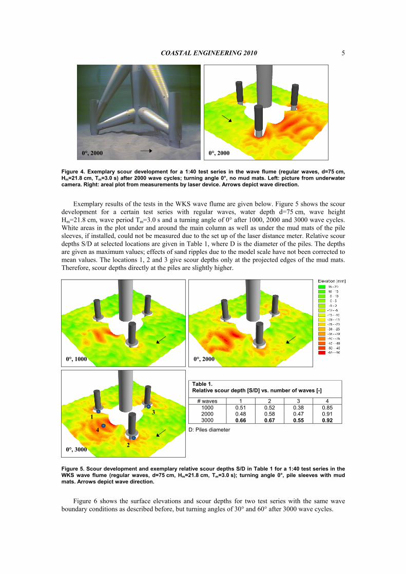
Figure 4. Exemplary scour development for a 1:40 test series in the wave flume (regular waves, d=75 cm, Hm=21.8 cm, Tm=3.0 s) after 2000 wave cycles; turning angle 0°, no mud mats. Left: picture from underwater camera. Right: areal plot from measurements by laser device. Arrows depict wave direction.
Exemplary results of the tests in the WKS wave flume are given below. Figure 5 shows the scour
development for a certain test series with regular waves, water depth d=75 cm, wave height Hm=21.8 cm, wave period Tm=3.0 s and a turning angle of 0° after 1000, 2000 and 3000 wave cycles. White areas in the plot under and around the main column as well as under the mud mats of the pile sleeves, if installed, could not be measured due to the set up of the laser distance meter. Relative scour depths S/D at selected locations are given in Table 1, where D is the diameter of the piles. The depths are given as maximum values; effects of sand ripples due to the model scale have not been corrected to mean values. The locations 1, 2 and 3 give scour depths only at the projected edges of the mud mats. Therefore, scour depths directly at the piles are slightly higher.
Table 1. Relative scour depth [S/D] vs. number of waves [-]
# waves 1 2 3 4 1000 0.51 0.52 0.38 0.85 2000 0.48 0.58 0.47 0.91 3000 0.66 0.67 0.55 0.92
D: Piles diameter
Figure 5. Scour development and exemplary relative scour depths S/D in Table 1 for a 1:40 test series in the WKS wave flume (regular waves, d=75 cm, Hm=21.8 cm, Tm=3.0 s); turning angle 0°, pile sleeves with mud mats. Arrows depict wave direction.
Figure 6 shows the surface elevations and scour depths for two test series with the same wave
boundary conditions as described before, but turning angles of 30° and 60° after 3000 wave cycles.
0°, 1000 0°, 2000
0°, 3000
3
2
1
4
0°, 2000 0°, 2000

COASTAL ENGINEERING 2010 6
Figure 6. Surface elevation and sour depths for a 1:40 test series in the WKS wave flume (regular waves, d=75 cm, Hm=21.8 cm, Tm=3.0 s) after 3000 wave cycles; turning angle 30° (left) and 60° (right), pile sleeves with mud mats. Arrows depict wave direction.
From all tests that have been carried out, it can generally be stated that the (as far as possible)
measured scour depths and extends at the piles of the foundation as well as local bed level changes in the near-field of the structure are influenced by and are depending on the wave parameters and the turning angles of the structure (e.g. the piles) facing the incoming main wave direction (here: wave paddle). The examined turning angles 0° (one pile facing the wave paddle), 60° (two piles) and 30° (asymmetric constellation) result in different characteristics of local scour development and maximum scour depths. Furthermore, it can be stated that scours do not only occur directly at the foundation piles, but also in the near-field and between the single piles. By this means crucial qualitative insights and advancement of knowledge on scour development and extent in the vicinity of tripod foundation structures in small-scale laboratory facility has been achieved.
Large-scale experiments, model setup and results To further analyze the scouring phenomena around the tripod structure in detail and under
minimized laboratory modeling effects, esp. with regard to the scaling of the model sediment, the large-scale physical model tests have been carried out on a length scale of 1:12 in the Large Wave Flume in Hanover (dimensions: length 310 m, width 5.0 m, height 7.0 m) in 2010, in combination with tests on the forces and general effects on the tripod structure due to breaking waves.
To conduct the experiments, a moving bed with fine sand (which was already used in the 1:40 laboratory experiments) covering a horizontal area of around 175 m² has been installed in the flume with a bed depth of 1.2 m, in combination with ramps of the same sand in front and behind the horizontal investigation area (slopes 1:20 and 1:15) as well as a drainage system. The tripod model has been constructed and installed in the middle of the investigation area by a solid connection to the floor. For the experiments the structure could be rotated through 180 degrees around the z axis so that the already mentioned turning angles of 0 and 60° given from laboratory experiences in small scale could be examined.
For the investigations on scour developments and flow pattern, the tripod model has been
equipped with various measuring sensors that are described below; positions can also be taken from Figure 7 and Figure 8. Wave heights have been measured by capacitive wave gauges that have been installed along the channel and been concentrated around the tripod. Orbital velocities have been measured by means of 2D velocity meters (electromagnetic probes) installed at two different locations at the side walls in the near-field of the tripod. For the determination of flow pattern around the structure, flow velocities have been measured by use of different devices. On the one hand, four 1D propellers (Schiltknecht) have been installed at certain locations directly at the structure for a permanent measurement of the velocities in the longitudinal direction of the flume. On the other hand, four ADV probes (Nortek Vector and Vectrino+ probes) have been installed on a vertical profile on top of each other and have been mounted on a 3D positioning platform above the flume, being able to move the probes at different locations around the tripod in order to measure vertical velocity profiles.
60°, 3000 30°, 3000

COASTAL ENGINEERING 2010
7
Figure 7. Installation of the 1:12 tripod model in the Large Wave Flume. Right: Locations of installed measuring equipment for scour and flow investigations. Arrows depict measuring direction of the devices.
Conclusions on the development of pore pressures in the soil during the experiments can be drawn
from pressure sensors which have been installed at different locations and height profiles around and between the piles. For the protection of the pressure membranes, geotextiles have been used.
The measurements of the bed level changes and scour development again has been carried out by use of different sensors. The technique for measuring the large-area development is a multi-beam echo sounder (Reson SeaBat) mounted on the 3D positioning platform, which collects stripes of bed profiles while moved over ground along the flume. In the post-processing, areal plots of the bed elevations can be calculated (Figure 9 et seqq.). For the validation of the collected data and the extension of the measuring locations, two sets of three down-looking Acoustic Backscatter probes (Aquatec AQUAScat 1000) have been installed at one of the piles and around the main column, which have been used as single-beam echo sounders. An additional single-beam echo sounder has been installed under the main column. At the locations beneath the mud mats where the technique of echo sounding was not feasible, four underwater cameras have been used for the determination of the soil levels directly at the piles. The cameras have been installed pair-wise inside of two of the piles, recording the level changes through Plexiglas windows during the experiments.
As boundary conditions for the test series, selected conditions derived from the 1:40 experiments
in the small wave flume have been chosen. In most cases, these have been scaled for the 1:12 tests by use of the Froude’s model law. The wave boundary conditions for regular waves and JONSWAP wave spectra were in a range of Hm/Hs= 0.51-0.77 m and Tm/Tp= 2.78-5.52 s; the water level was kept at 2.5 m for all test conditions. See Table 2 for details on the boundary conditions. Turning angles of 0° and 60° have been investigated. The maximum number of waves per test series was up to 4000 waves, depending on the wave and initial conditions. For about half of the test series, a plane initial bed level was established. For the other tests, a series of two/three consecutive single tests with increased wave heights and/or wave periods has been carried out.
Wave gauges
2D velocity meters
3 ABS sensors
3 ABS sensors
Propeller
UW cameras
17 pressure sensors

COASTAL ENGINEERING 2010 8
Figure 8. Measuring equipment for scour and flow investigations: a) ADV probes on vertical profile, b) Multi-beam echo sounder mounted on 3D positioning platform, c) ABS probes and propeller at the pile sleeve, d) Uncorrected multi-beam records, e) Pore pressure sensors and Plexiglas window in the pile
Table 2. Boundary conditions for the 1:12 test series on scours
No d [m]
Regular wave/ JONSWAP
Hm/Hs
[m] Tm/Tp
[s] Turning angle [°]
Plane initial bed
Max # waves [-]
1 2.5 RW 0.51 2.78 60 x 3000 2 2.5 RW 0.77 3.55 60 4000 3 2.5 RW 0.76 5.48 60 2500 4 2.5 RW 0.76 5.48 60 x 3500 5 2.5 JONSWAP 0.70 3.60 60 x 2500 6 2.5 JONSWAP 0.72 5.52 60 3000 7 2.5 JONSWAP 0.70 3.60 0 x 2500 8 2.5 JONSAWP 0.72 5.52 0 3000 9 2.5 JONSWAP 0.72 5.52 0 x 3000
10 2.5 RW 0.77 3.55 0 x 4000 11 2.5 RW 0.76 5.48 0 3000 12 2.5 RW 0.76 5.48 0 x 3500
For each test series, the areal bed level changes have been measured by use of the multi-beam echo
sounder after intervals of 250, 500 or 1000 waves. All the remaining above mentioned measuring instruments permanently collected data during the tests. A series was terminated after the maximum number of waves given in Table 2 was reached, achieving (in most cases) an equilibrium state.
Exemplary results of selected tests on scour investigations in the GWK are given below. Figure 9
shows the scour development for a series with regular waves, water depth d=2.5 m, wave height Hm=0.76 m, wave period Tm=5.48 s and a turning angle of 0° after 1000, 2000 and 3000 wave cycles. White areas in the plots under and around the main column as well as under the mud mats could not be determined by the multi-beam echo sounder and are therefore not given in the areal plots in the figures. For these locations, the point-wise measurements using the single-beam echo sounders are available, as well as records from the underwater cameras. Relative scour depths S/D at selected locations are given in Table 3, where D is the diameter of the piles. Depths are again given as maximum values; effects of sand ripples can be neglected due to the large scale of the experimental setup and therefore the negligible impact on the scour development. The locations 1, 2 and 3 give scour depths at the projected edges of the mud mats recorded by the multi-beam echo sounder. Locations 1P and 3P give scour
a)
d) e)
Sonar head
3D positioning platform
3 ABS sensors Propeller
Plexiglas
Pressure sensors
b) c)

COASTAL ENGINEERING 2010
9
depths directly at the piles, recorded by the underwater cameras; location MC gives scour depths under the main column, recorded by the single-beam echo sounder.
Figure 9. Scour development for a 1:12 test series in the wave flume (regular waves, d=2.5 m, Hm=0.76 m, Tm=5.48 s); turning angle 0°. Arrows depict wave direction.
Table 3. Relative scour depth [S/D] vs. number of waves [-] in Figure 9
# waves 1 1P 2 3 3P 4 MC 1000 0.82 0.98 0.93 0.72 0.72 0.05 1.00 2000 1.05 1.14 1.03 0.77 0.77 0.21 1.14 3000 1.05 1.13 1.03 0.80 0.82 0.31 1.11
D: Piles diameter
Additional results for two test series with JONSWAP spectra (water depth d=2.5 m, wave height
HS=0.72 m and wave period TP=5.52 s) for the turning angles of 0° and 60° are given in Figure 10, showing the bed evolution and scour depths after about 3000 waves.
A comparison of the results derived from the 1:12 experiments with different turning angles of 0°
(one pile facing the wave paddle) and 60° (two piles) leads to the conclusion that the characteristics of the local and global scour development are significantly depending on the incoming wave direction. This finding is supported by the 1:40 laboratory experiments. Local scour depths at the piles behind the structure in reference to the incoming wave direction are slightly higher than in the front of the tripod.
Regular wave conditions with values of the wave heights Hm and periods Tm similar to Hs and Tp from the irregular wave conditions in the tests led to a higher sediment mobility around the structure forming more distinct global scours. Nevertheless, scour depths measured at the piles and under the main column were of similar magnitude. Generally, scours do not only occur directly at the piles, but also in the near-field or beneath the main column of the structure, as it is partially validated from the findings given in the small-scale experiments. These scours can reach even larger depths than directly measured around the piles of the foundation.
From a direct comparison of the results derived from the small and the large-scale experiments using equal but scaled wave boundary conditions and after reaching an (almost) equilibrium state, it can be stated that the scour depths (for wave boundary conditions in Figure 6 and Figure 9) measured at the projected edges of the mud mats in the 1:12 experiments were in an order of 50 percent higher
0°, 1000 0°, 2000
0°, 3000
3, 3P
2
1, 1P
4
MC
0°, 3000 3, 3P
1, 1P 2 MC

COASTAL ENGINEERING 2010 10
than in the 1:40 experiments. Scour depths around the piles are again slightly higher than measured at the edges of the mud mats. Furthermore, ripples formed in the bed of the 1:40 tests have an influence on the measured scour depths, leading to locally different scours/bed changes, especially in the near-field of the structure. These results are evidently justified due to the fact that the same sediments have been used in both laboratory facilities.
Figure 10. Bed levels for two 1:12 test series in the wave flume (JONSWAP wave spectra, d=2.5 m, HS=0.72 m, TP=5.52 s) after 3000 waves; turning angles are given in the plots. Arrows depict wave direction.
Table 4. Relative scour depth [S/D] vs. number of waves [-] in Figure 10
1P 3P MC a) 0.93 0.88 1.08 b) 0.66 1.10 1.16
D: Piles diameter
Scour monitoring in the test site Within the framework of the RAVE cooperation, a scour monitoring campaign is carried out by
the German Federal Maritime and Hydrographic Agency (BSH). To monitor the real scour development at the foundation piles and around the structures, one of the tripods in the test site (M7) has been equipped with 19 permanently measuring single-beam echo sounders, which have been installed around the piles and beneath the main column. This local data acquisition program is furthermore completed by large-area vessel supported surveys of the sea bed around the field of structures using multi-beam echo sounders. All collected data will be thoroughly evaluated within this work package in a later stage of the project and will, in addition to the results derived from the physical model tests, be used for the correlation with and verification of the numerical CFD codes, which is work in progress.
Figure 11 gives a qualitative comparison of scours around the M7 tripod derived from a measuring
campaign in the alpha ventus test site in April 2010 (as 1x1 m grid) and a large-scale physical model test in the GWK. The mean water level at the M7 tripod is approximately 30 m. Maximum observed in-situ scour depths at the structure are in a range of about 2.5 m and 3.3 m around the single piles and 5.5 to 5.8 m beneath the main column. Lambers-Huesmann (2010) argue that this observation and scour magnitudes resemble as a fully developed and steady state condition. In effect, S/D values of 1.1 and 1.4 at the piles as well as a maximum value of 2.5 beneath the main column are given with D≈2.3 m as the pile diameter in all cases. Regarding the measurements from the test site and the physical model tests carried out in the GWK given in Figure 11, it can be derived that at least a qualitative good agreement between the development and the overall extent of the local and global scour around the structure is given. Independent of scales in nature and laboratory, maximum scour depths and shapes of scour phenomena take place at similar hot spots around the structure.
0°, 3000
1P
3P MC
3P
2P≈1P
MC
60°, 3000
a) b)
1P

COASTAL ENGINEERING 2010
11
Nevertheless, S/D magnitudes in the large-scale experiments were lower than observed in prototype, especially in the area beneath the main column. This is concluded to be caused mainly due to the following effects: 1. In the experiments, simplified wave conditions in a 2D wave tank have been used as unidirectional
wave boundary conditions. Due to external data restrictions, the real sea state conditions and predominant wave directions in the test site leading to the above mentioned scour depths could not yet be analyzed.
2. Due to the setup of the wave flume, combined wave-current interactions, stemming from tide-dominated current effects in prototype scale, could not be taken into account.
3. Although the model scale of 1:12 can be seen as a large-scale experiment, typical model scaling effects especially regarding the model sediment could have had an effect on the results. The influence and interaction of these effects on the scour developments will be further analyzed
in detail, especially by means of numerical investigations with real sea state conditions including a wave-current interaction on a prototype scale that will be carried out as a next step in the work package.
Multi beam survey April 2010, 1x1 m uncorrected grid.Source: Lambers-Huesmann & Zeiler, BSH 2010
JONSWAP spectrum: d=2.5 m, HS=0.72 m, TP=5.52 s
Figure 11. Qualitative comparison of real scour depths around the M7 prototype tripod in the alpha ventus test site (left) and scour depths derived from a large-scale physical model test (right). Main wave directions are depicted in the figures.
CONCLUSIONS Within the above described work package of the research project Gigawind alpha ventus,
investigations on scour phenomena around the tripod foundation structure for offshore wind energy converters in the first German offshore test site alpha ventus have been carried out by means of 1:40 laboratory tests and 1:12 large-scale physical model tests in wave flumes. For the experimental setups, a moving bed using fine sand has been installed in the flumes. Scour developments have been measured by use of a laser distance meter (1:40) and multi-beam as well as single-beam echo sounders, ABS probes and underwater cameras (1:12).
The characteristics of the local and global scour development described by depths and extent are directly influenced by the wave parameters and the orientation, i.e. turning angles of the tripod in reference to the main wave direction. It can generally be concluded that scours occur directly at the piles and also in the near-field and beneath the main column of the tripod, in some cases reaching even higher scour depths than expected around the piles. Therefore, the influence of the global changing bed surface on the soil-mechanical bed characteristics has to be considered when regarding the stability of the soil and the structure itself. With regard to scaling effects in the model setups it can be stated that in the examined test results, local scour depths in the large-scale experiments were in an order of 50 percent higher than in the small-scale laboratory tests. A comparison between large-scale model results and in-situ measurements of scours in the test site has shown that the local and global scour pattern can
W W-WSW

COASTAL ENGINEERING 2010 12
qualitatively be reproduced in the experiments quite well, although scour depths were slightly lower due to restrictions in the wave flume model setup.
The data gained from the experiments and the in-situ measurements will later be used for the calibration and verification of the numerical CFD model that will be used for the further analysis of the scour phenomena.
ACKNOWLEDGEMENTS The authors gratefully acknowledge the support of the German Federal Environment Ministry
(BMU) within the funded project "Ganzheitliches Dimensionierungskonzept für OWEA-Tragstrukturen hinsichtlich Lasten, Langlebigkeit, Gründung und Gesamtstruktur (GIGAWIND alpha ventus - LUH)" (BMU code 0325032). Project details and cooperation partners can be collected from www.gigawind.de.
REFERENCES DHI. 2007. Borkum West - Hydrographische Standortbedingungen, Modellierung und Statistische
Analyse. Abschlussbericht Rev. 2.2 Hoffmans, G.J.M.C., Verheij, H.J., 1997. Scour Manual. Balkema, Rotterdam Lambers-Huesmann, M., Zeiler, M. 2010. Personal communication on scours measured in the German
offshore test site alpha ventus Rolfes, R., Huhn, H., Schaumann, P., Schlurmann, T., Lohaus, L., Achmus, M., Haake, G. 2008.
Support structures for offshore wind turbines – a holistic design concept, Leibniz University Hanover and Fraunhofer-CWMT Bremerhaven, DEWEK 2008
Stahlmann, A., Hildebrandt, A., Schlurmann, T. 2009. Investigations on Scour Development at Offshore Wind Energy Converters in the German Offshore Test Site alpha ventus, 33rd International Association of Hydraulic Engineering & Research (IAHR) Biennial Congress, Vancouver, pp. 3311-3318
Sumer, B.M., Fredsøe, J. 2002. The Mechanics of Scour in the Marine Environment, World Scientific Publishing Co. Pte. Ltd.
Whitehouse, R.J.S. 1998. Scour At Marine Structures - A Manual for Practical Applications, Thomas Telford Limited