Embed Size (px)
Citation preview

25 March 2009 NDC Business System R2Letterhead (scale 80%) Option #1
47533 Westinghouse Drive Fremont, California 94539 t 510.683.2000 f 510.683.2001
We are Nitinol.™
www.nitinol.com
PhysicalPropertiesofEndovascularStents:AnExperimentalComparison
Duda,Wiskirchen,Tepe,Bitzer,Kaulich,Stoeckel,Claussen
JVIR11pp.645‐654
2000

Physical Properties of Endovascular Stents: An Experimental Comparison 1
Stephan H. Duda, MD Jakub Wiskirchen, MD Gunnar Tepe, MD Michael Bitzer. MD Theodor W. Kaulich, PhD Dieter Stoeckel, PhD Claus D. Claussen. MD
Index terms: Arteri el!, grafts and pro&theses . Arteries., tran$luminal a ngioplast)' . Flue>roseopy . S tan ts and pl'O!Ithe~
JVlR 2000; 11:645-654
! From the Department of Radiology (S.H.D .. J .W., G.T., M.B., T.W.K. , C.O.C.). Eberhard-JC.rl$·Univertitiit T\lbingen, G<!rma ny; and Nit inol Devices & Compo. nents (o.S .), Fremont. California . From the 1999 SCVIR a nnual meeting. R~iYed M-.y 28, 1999; ~i.ion requested July 18; fi nal ~vision received November 8; aeoepted November 9. Supported in part by a grant from Cord is. Address correSpOndence to S.H.D., Division of OiagnGSt ic Radiology, Eber · hard·Karb ·Universilit Tllbingen, Hoppe· Seyler.str. 3, 12076 TIlbingen, Germany; £omeil: [email protected]
OSCV1R. 2ooo
PURPOSE: Different endovascular stent types (AVE Bridge, AVE Bridge X, Memotherm, Palmaz Large, Palmaz Medium, PalmazSchatz Long-Medium, Perflex, S.M.A.R.T., Symphony, and Wallstent) of 4 em length and 8 mm diameter were subjected to standardized physical tests.
MATERIALS AND METHODS: The metal mass of each stent was assessed by weighing. The balloon-expandable stents were pneumatically tested for hoop strength. In self-expanding stents, radial resistive force and chronic outward force were detennined with use of a loop test. Stent delivery system pusbability was assessed in a crossover model. Stent radiopacity was analyzed quantitatively.
RESULTS: The hoop strength of the baUoon-expandable stents ranged from 15.8 NIcOl (Perflex) to 28.9 Nlcm (AVE Bridge X). The stent weight increased with greater hoop strength (Perflex. 0.046 gfcm vs. AVE Bridge X, 0.061 gfcm) . The self-expanding stents had a radial resistive force between 0.39 NIcOl (Wallstent) and 1.7 Nlcm (Smart). The flexible balloon-expandable stents showed pushability values between 0.13/N (AVE Bridge) and 0.20/N (Perflex). The selfexpanding stents had flexibilities between O.13/N (Memotherm) and 0.241N (Symphony). Radiopacity assessed with use of a phantom simulating the iliac region ranged. from 92 <Palmaz Large) to 115 (AVE Bridge) 00 a 256·point gray scale (0 = black, 256 = white).
CONCLUSIONS: There is no stent with ideal physical properties. However, depending on the characteristics of the arterial lesion to be treated, the most appropriate steot can be chosen.
SINCE 1969, stents have been pursued as a supplement or as an alternative to conventional balloon angioplasty for the treatment of arterial occlusive disease (1 ). In the last decade, various stent designs have been developed (Z). In any structure, physical properties playa key role in structural performance. For example, insufficient hoop strength of vascular stents may result in inadequate expansion and may bring along an increased frequency of restenosis or even obstruction that usually prompts further interventions (3-5). These interventions encompass repeated balloon dilatations or coaxial insertion of additional stents. Unsatisfactory
results during stent placement include insufficient stent expansion or extrinsic stent compression. Even with the rigid Palroaz stent design there have been reports about cases of stent collapse (6). Stent stability often is associated with lower flexibility and vice versa (7). There is evidence that low-profile, high hoop strength stents evoke a lesser degree of neointima formation than high-profile, low hoop strength stents (8).
Although numerous animal and clinical studies in humans have been performed to prove the usefulness of intravascular stents, only few studies were made to examine the basic mechanical properties.
645
646 • Physical Properties of Endovascular Stents
May 2000 JVIR
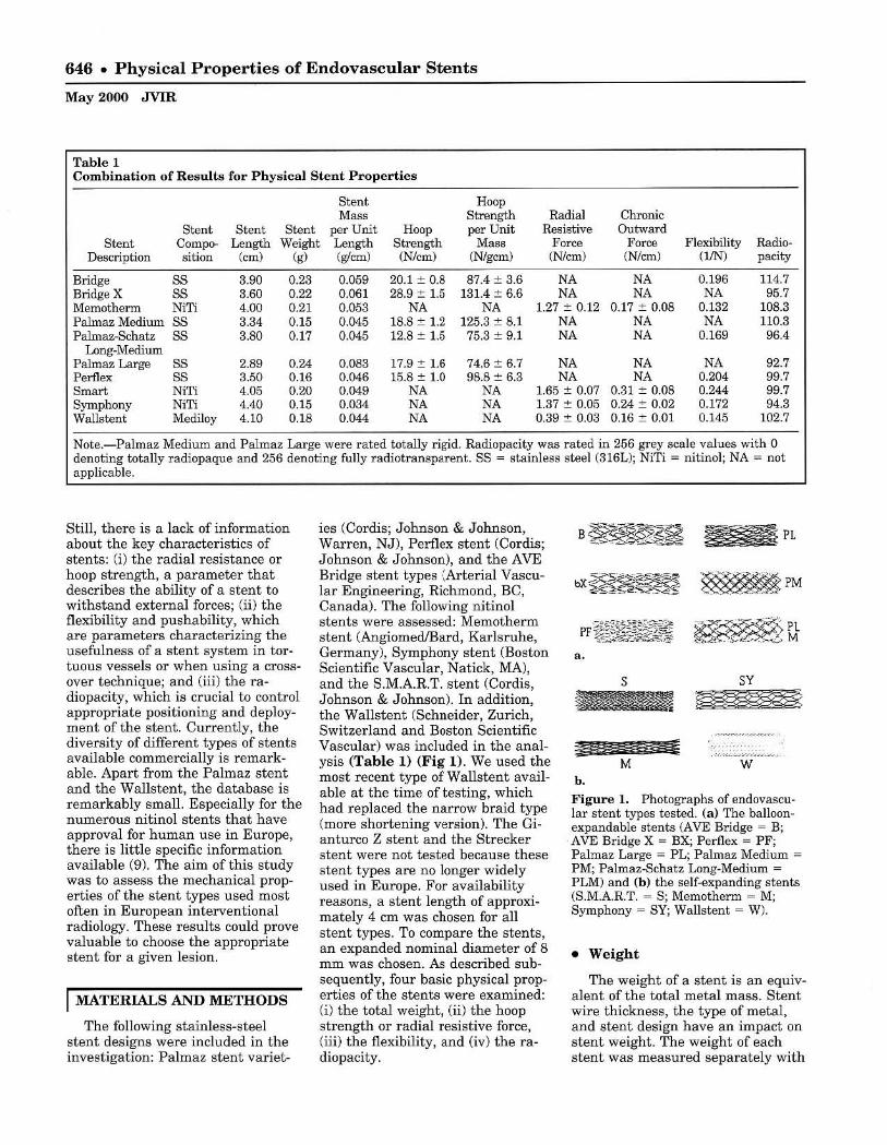
Table 1 Combination of Results for Physical Stent Properties
Stent Hoop MM' Strength Radial Chronic
Stent Stent Stent per Unit Hoop per Unit Resistive Outward Stent Compo- Length Weight Length Strength Mass Force Force Flexibility Radio-
Description sition (cm) (g) (glcm) (N/em) (N/gcm) (Nlcm) (N/cm) (1JN) pacity
Bridge SS 3.90 0.23 0.059 20.1 :+:: 0.8 87.4 :t 3.6 NA NA 0.196 114.7 Bridge X 88 3.60 0.22 0.061 28.9:t 1.5 131.4 :t 6.6 NA NA NA 95.7 Memotherm NiTi 4.00 0.21 0.053 NA NA 1.27 ::': 0.12 0.17:+:: 0.08 0.132 108.3 Palmaz Medium S8 3.34 0.15 0.045 18.8 :+:: 1.2 125.3 :t 8.1 NA NA NA 110.3 Palmaz-&:hatz S8 3.80 0.17 0.045 12.8 :t 1.5 75.3 :t 9.1 NA NA 0.169 96.4
Long-Medium Palmaz Large 88 2.89 0.24 0.083 17.9::': 1.6 74.6 :t 6.7 NA NA NA 92.7 Perflex S8 3.50 0.16 0.046 15.8::': 1.0 98.8 ::': 6.3 NA NA 0.204 99.7 8m"" NiTi 4.05 0.20 0.049 NA NA 1.65 :t 0.07 0.31 ::': 0.08 0.244 99.7 Symphony NiTi 4.40 0.15 0.034 NA NA 1.37 ::': 0.05 0.24:+:: 0.02 0.172 94.3 Wallstent Mediloy 4.10 0.18 0.044 NA NA 0.39 :t 0.03 0.16:+:: 0.01 0.145 102.7
Note.-Palmaz Medium and Palmaz Large were rated totally rigid. Radiopacity was rated in 256 grey scale values with 0 denoting totally radiopaque and 256 denoting fully radiotransparent. SS = stainless steel (316L); NiTi = nitinol; NA = not applicable.
Still, there is a lack of infonnation about the key characteristics of stents: (i) the radial resistance or hoop strength, a parameter that describes the ability of a stent to withstand external forces; (ii) the flexibility and pushability, which are parameters characterizing the usefulness of a stent system in tortuous vessels or when using a crossover technique; and (iii) the radiopacity, which is crucial to control appropriate positioning and deployment of the stent. Currently, the diversity of different types of stents available commercially is remarkable. Apart from the Palmaz stent and the Walls tent, the database is remarkably small. Especially for the numerous nitinol stents that have approval for human use in Europe, there is little specific information available (9). The aim of this study was to assess the mechanical properties of the stent types used most often in European interventional radiology. These results could prove valuable to choose the appropriate stent for a given lesion.
I MATERIALS AND METHODS
The following stainless-steel stent designs were included in the investigation: Palmaz stent variet-
ies (Cordis; Johnson & Johnson, Warren, NJ), Perflex stent (Cordis; Johnson & Johnson), and the AVE Bridge stent types ':Arterial Vascular Engineering, Richmond, Be, Canada). The following nitinol stents were assessed: Memotherm stent (Angiomed/Bard, Karlsruhe, Germany), Symphony stent (Boston Scientific Vascular , Natick, MA), and the S.MAR.T. stent (Cordis, Johnson & Johnson). In addition, the Wallstent (Schneider, Zurich, Switzerland and Boston Scientific Vascular) was included in the analysis (Table 1) (Fig 1). We used the most recent type of Wallstent available at the time of testing, which had replaced the narrow braid type (more shortening version). The Gianturco Z stent and the Strecker stent were not tested because these stent types are no longer widely used in Europe. For availability reasons, a stent length of approximately 4 cm was chosen for all stent types. To compare the stents, an expanded nominal diameter of 8 mm was chosen. As described subsequently, four basic physical properties of the stents were examined: (i) the total weight, (ii) the hoop strength or radial resistive force , (iii) the flexibility, and (iv) the radiopacity.
PL
~PM
a.
Sy
w b.
Figure 1. Photographs of endovascular stent types tested. (a) The balloonexpandable stents (AVE Bridge = B; AVE Bridge X = BX; Perflex = PF; Palmaz Large = PL; Palmaz Medium = PM; Palmaz-Schatz Long-Medium = PLM) and (b) the self-expanding stents (S.M.A.R.T. = S; Memotherm = M; Symphony = SY; Wallstent = W).
• Weight
The weight of a stent is an equivalent of the total metal mass. Stent wire thickness, the type of metal, and stent design have an impact on stent weight. The weight of each stent was measured separately with

a special scale able to measure within the milligram range (PR 5002; Mettler Toledo, Greifensee, Switzerland). The measurement was repeated five times.
• Hoop Strength/RadiaJ Resistive Force/Chronic Outward Force
The testing methodologies for baUoon-expandable and self-expanding stents have evolved along different paths. The hoop strength measures the ability of a stent to withstand the radial compressive forces of stenotic vessels after dilation. The hoop strength test assesses the pressure required to collapse a stent that has been expanded to the rated burst pressure of the balloon. The hoop strength was assessed for the balloon-expandable stents. Because a collapse of self-expanding stents will usually be temporary, a test design was developed that can give more information about th e specific characteristics of self-expanding stents . The force exerted by a self-expanding stent is a function of the presence or absence of an external loading force. Thus, the chronic outward force is a measure of the force the stent exerts on the artery as it tries to expand to its nomi nal diameter when the vessel is relaxed. The radial resistive force is a measure of the force the stent exerts as it resists squeezing by constriction of the artery. The terms chronic outward force and radial resistive force have been coined by Duerig and Stoeckel to better describe the specific characteristics of nitinol stents (9).
For the hoop strength test, the sample size calculation (see Statistics section) yielded a minimum number of eight stents to be tested. We tested 10 sample slents. The stents were positioned in a compliant Dynalek tube (Dynatek Dalta Laboratories, Springfield, MOl. The inner diameter of the tube was 6.5 mm, which was 1.5 mm smaller than the inner diameter of the stents. The tube was placed in an airtight pressure device with a range from 0.14 to 7 bar (B06-l0 l moVL2KD; IMI Norgren, Littletown,
CO). The hoop strength fixture was placed in a cabinet at 37°C =. 2°. The stents were expanded by inflating the stent delivery system to the rated burst pressure. The balloon inflation pressure was held for 20 seconds before deflating the stent delivery system. The pressure for balloon inflation was monitored with use of a gauge with a range of 0-500 psi (Omega DPG-500; Sealed Unit Parts, Allenwood, NJ). The expanded stents were positioned in the center of the hoop strength fixture with an additional 2 mm length of tubing on either side of the expanded stent. Nitrogen pressure was increased in 0.3-psi increments until total collapse of the slented tube was observed. We measured and recorded the pressure required for total collapse. With the help of video supervision, the exact moment of total stent collapse was determined. After collapse, the stents were scrutinized for breakages or other severe damage of the wire mesh. Data were originally recorded in psi. We recalculated the mean pneumatic hoop strength in N/cm by considering the circumference of the balloon-expandable stents to get the same units of measure as used for the radial resistance in self-expanding stents by the following formula: 1 psi = 0.689 N/cm2
. The circumference of a stent at 8 mm diameter equals 2 x r = 2.51 cm. Hence, the mean pneumatic hoop strength in Nlcm is 1.73 x psi. It should be noted, however, that even though the pneumatic hoop strength numbers for the balloon-expandable stents were converted to the same units (N/cm ) as used with the radial resistance force for self-expanding stent s, the numbers are not comparable. On the one hand, the threshold pressure for stant collapse was evaluated for the balloon expandable slents. On the other hand, the radial resistive force and chronic outward force, two parameters depending on the state of compression, were evaluated for the self-expanding stents. This is because the test used on the balloon-expandable stents applied a radial force while the test used with the self-expand-
Duda et aI • 647
Volume 11 Number 5
,
• !
\'1, ........
.... ' " .... ,r_ _ ....
Figure 2. &hematic drawing of defor· mation characteristics of a nitinol stent during a loading/unloading cycle. The test starts with the stent in a crimped state (a). The stent is then unloaded to its nominal outer diameter minus 1 mm (b) . The load at this point is equivalent to the chronic outward force. The stent is then crimped back to its nominal outer diameter minus 2 mm (c) . This load is reported 8S the radial resistive force. The force hysteresis curve (solid and interrupted lines) means that the stent exerts a much smaller outward force (solid arrow) but resists deformation with a much greater force (open arrow). The right insert shows a d.iagram of the test device for radial force measurement (MTS = mechanical test system; mylar loop = polyester film).
ing stents a pplied a circumferential force.
Chronic outward force and radial resistive force were measured with use of a high·strength polyester thin film (Mylar; DuPont, Wilmington, DE) that was looped around the stents and threaded through a narrow gap between rollers. One end of the film was attached to a fixed base, while the other end was attached to the crosshead of a materia l test machine (Mini Bionix model 858; MTS Systems, Eden Praire, MN). On loading (ie, as the crosshead moved up), the loop decreased in diameter and compressed the stente circumferentially (Fig 2) . The width or the Mylar film was adapted to the length of the slents and had a thickness of 0.001 inch . The test was performed in a temperature-controlled water circulator (model DC1; Haake, Paramus, NJ) at 37°C :!: 1° and started with. the stent in a crimped state, simulating the delivered size (10). The stent was then unloaded to its nominal outer diameter minus 1 mm. The
648 • Physical Properties of Endovascular Stents
May 2000 JVIR
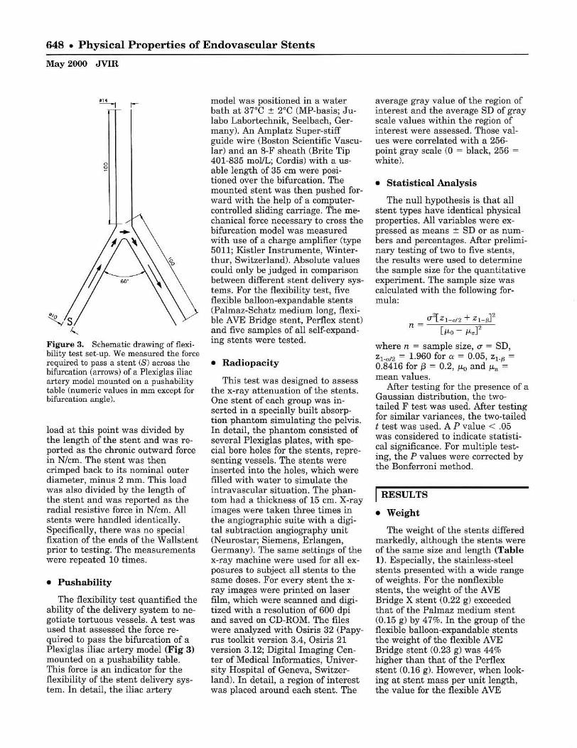
Figure a. Schematic drawing offlexi· bility test set-up. We measured the force required to pass a stent (8) across the bifurcation (arrows) of a Plexiglas iliac artery model mounted on a pushability table (numeric values in mm except for bifurcation angle).
load at this point was divided by the length of the stent and was reported as the chronic outward force in N/cm. The stent was then crimped back to its nominal outer diameter, minus 2 mm. This load was also divided by the length of the stent and was reported as the radial resistive force in N/cm. All stents were handled identically. Specifically, there was no special fixation of the ends of the Wallstent prior to testing. The measurements were repeated 10 times.
• Pushability
The flexibility test quantified the ability of the delivery system to negotiate tortuous vessels. A test was used that assessed the force required to pass the bifurcation of a Plexiglas iliac artery model (Fig 3) mounted on a pushability table. This force is an indicator for the flexibility of the stent delivery system. In detail, the iliac artery
model was positioned in a water bath at 37°C :t 2°C (MP-basis; Julabo Labortechnik, Seelbach, Germany). An Amplatz Super-stiff guide wire (Boston Scientific Vascular) and an 8-F sheath (Brite Tip 401-835 mol/L; Cordis) with a usable length of 35 cm were positioned over the bifurcation. The mounted stent was then pushed forward with the help of a computercontrolled sliding carriage. The mechanical force necessary to cross the bifurcation model was measured with use of a charge amplifier (type 5011; Kistler Instrumente, Winterthur, Switzerland). Absolute values could only be judged in comparison between different stent delivery systems. For the flexibility test, five flexible balloon-expandable stents (Palmaz-Schatz medium long, flexible AVE Bridge stent, Perflex stent) and five samples of all self-expanding stents were tested.
• Radiopacity
This test was designed to assess the x-ray attenuation of the stents. One stent of each group was inserted in a specially built absorption phantom simulating the pelvis. In detail, the phantom consisted of several Plexiglas plates, with special bore holes for the stents, representing vessels. The stents were inserted into the holes, which were filled with water to simulate the intravascular situation. The phantom had a thickness of 15 em. X-ray images were taken three times in the angiographic suite with a digital subtraction angiography unit (N eurostar; Siemens, Erlangen, Germany). The same settings of the x-ray machine were used for all exposures to subject all stents to the same doses. For every stent the xray images were printed on laser film, which were scanned and digitized with a resolution of 600 dpi and saved on CD-ROM. The files were analyzed with Osiris 32 (Papyrus toolkit version 3.4, Osiris 21 version 3.12; Digital Imaging Center of Medical Informatics, University Hospital of Geneva, Switzerland). In detail, a region of interest was placed around each stent. The
average gray value of the region of interest and the average SD of gray scale values within the region of interest were assessed. Those values were correlated with a 256-point gray scale (0 = black, 256 = white).
• Statistical Analysis
The null hypothesis is that all stent types have identical physical properties. All variables were expressed as means ± SD or as numbers and percentages. After preliminary testing of two to five stents, the results were used to determine the sample size for the quantitative experiment. The sample size was calculated with the following formula:
(J"2[ZI-c>l2 + Z l _ ~P
n = [ILo ILaF
where n = sample size, (J" = SD, Zl.cd2 = 1.960 for a = 0.05, Z l.~ = 0.8416 for f3 = 0.2, JLo and JLa = mean values.
After testing for the presence of a Gaussian distribution, the twotailed F test was used. After testing for similar variances, the two-tailed t test was used. A P value < .05 was considered to indicate statistical significance. For multiple testing, the P values were corrected by the Bonferroni method .
I RESULTS
• Weight
The weight of the stents differed markedly, although the stents were of the same size and length (Table 1). Especially, the stainless-steel stents presented with a wide range of weights. For the nonflexible stents, the weight of the AVE Bridge X stent (0.22 g) exceeded that of the Palmaz medium stent (0.15 g) by 47%. In the group of the flexible balloon-expandable stents the weight of the flexible AVE Bridge stent (0. 23 g) was 44% higher than that of the Perflex stent (0.16 g). However, when looking at stent mass per unit length, the value for the flexible AVE

Table 2 Results of Multiple Testing for Differences in Pneumatic Hoop Strength Between Balloon-expandable Stents
Palmaz Medium X X Palmaz-Schatz
Long-Medium Palmaz Large X Perflex Bridge
J Bridge X
Bridge Bridge Perflex Palmaz Palmaz-Schatz Palmaz X 1=g' Long-Medium Medium
Note.-X = equal; blank boxes indicate significance at P < .05.
Bridge stent (0.059 g1cm) was only 28% higher than that of the Perflex stent (0.046 g/cm). The weights of the nitinol stents were comparable.
• Hoop Strength
Table 1 combines the hoop strength results of all balloon-expandable stents. In the first group, the AVE Bridge X stent showed the highest hoop strength, with an average value of 28.9 N/cm until total collapse. The capability of this stent to withstand radial forces exceeded that of the Palmaz medium stent by 54%. However, three of 10 samples of the AVE Bridge X stent broke into two parts during the collapse phase of the hoop strength testing. The fractures of the AVE Bridge X stent were found in the middle of the stents at the central welding points. Similar or other severe damages were not observed in any other stent type. The standard flexible AVE Bridge X stent did not develop wire breakages and exceeded the hoop strength of the Palmaz medium stent by 7%. This difference was not significant (Table 2). However, when comparing the hoop strength per unit mass (stent mass and stent design contribute directly to hoop strength), the Palmaz medium stent (125 N/cm"'g) was superior compared to the flexible AVE Bridge X stent (87 N/cm*g), and nearly similar compared to the rigid AVE Bridge X stent (131 N/cm*g). The other stents of the group (Perflex, Palmaz Large) displayed hoop
strength values per unit mass between 75 and 99 N/cm*g (Table I). Stent stability/hoop strength mainly depends on the following factors: (i) the stent design (ie, the orientation of the stent struts), (ij) the stent material, (iii) total stent mass, (iv) stent length,. and (v) stent diameter. The stents in our study were dilated to the same diameter (8 mm). Furthermore, all stents of the balloon-expandable group were made of stainless-steel. By bringing the measured hoop strengths into relation to the stent length and total mass, the only factor probably responsible for hoop strength differences should be the stent design.
Table 2 gives the results of the multiple statistical testing for differences in pneumatic hoop strength between balloon-expandable stents at a P level of .05. The Palmaz large stent was significantly different from neither the Palmaz medium stent nor the the Perflex stent.
• R adial Resistive Force/Chronic Outward Force
In the group of the self-expanding stents, the Wallstent proved to have a radial resistive force of 0.39 N/cm. The Memotherm stent and the Symphony stent both had nearly equivalent radial resistive force values, with 1.27 N/cm and 1.36 N/cm, respectively. The S.M.A.RT. stent had a radial resistive force of L 7 Nlcm <Table 1). The chronic outward force values
Duda et al • 649
Volume 11 Number 5
were well below the corresponding radial resistive force results. The Wallstent had the lowest chronic outward force, with 0.16 N/cm. The highest chronic outward force of 0.31 N/cm was obtained for the S.M.A.RT. stent. Statistically, all self-expanding stents showed significant differences in radial resistive force and chronic outward force at p < .05.
• P u shability
All stents passed the bifurcation without stent slippage or loss of the stent. The stent delivery system with the highest pushability was the Perflex stent system (Table I). The flexible standard AVE Bridge stent had comparable pushability. Except for the S.M.A.R.T. stent, the force needed for the self-expanding stents to pass the bifurcation was greater than needed for the Perflex stent and the flexible standard AVE Bridge stent. This may be attributable to a greater stiffness of the delivery catheter shafts. The PalmazScbatz Long-Medium stent behaved very much like the self-expanding stents in terms of cross-over pushability. Table 3 summarizes the results of the multiple statistical testing for differences in cross-over pushability between stents at a P level of .05. Except for the S.M.A.RT. stent and the Perflex stent, there was a considerable overlap between different stent types.
• Radiopacity
The stents with the best radiopacity values, meaning those with the lowest numbers in our radiopacity model, were the Palmaz large stent, the Symphony stent, the AVE Bridge X stent, and the Palmaz-Schatz Long-Medium stent, with absorption values ranging from 92.7 (Palmaz large stent) to 96.4 (Palmaz-Schatz Long-Medium stent). The next grouP. consisting of the S.M.A.R.T. stent, the Perflex stent, and the Wallstent, presented with absorption values ranging from 99.7 (S.M.A.RT. stent) to 102.7 (Wallstent). The last group

650 • Physical Properties of Endovascular Stents
May 2000 JVIR
Table 3 Results of Multiple Testing for Differences in Cross-over Flexibility Between all Flexible Stent Types Tested
Palmaz-Schatz X X X X Long-Medium
Perflex Bridge X Bridge X X X Smart Wallstent X X Memotherm , Symphony -Symphony Memotherm Wallstent Smart Bridge X
Note.-X = equal; blank boxes indicate significance at P < .05.
consisted of the Palmaz medium stent, the standard AVE Bridge stent, and the Memotherm stent. The absorption values of those stents varied from 108.3 to 114.7. Because of negligible standard deviations (between 0.58 and 1.57), all differences were significant in the statistical sense. However, the stent with the highest radiopacity (Palmaz large stent) had a value that was only 24% above that of the stent (AVE Bridge stent) with the lowest x-ray attenuation.
I DISCUSSION
Stent implantation has gained increasing acceptance as a valuable adjunct to balloon angioplasty. Elastic vessel recoil, significant residual stenosis by dissection or severe plaque burden, and treatment of acute or impending reocclusions are the main indications for the intra-arterial use of stents. Intravascular stents are also used to inhibit arterial restenosis and to improve the patency rates after percutaneous transluminal angioplasty. Stent design is believed to playa major role concerning the effectiveness of stents (8,11-15). However, biologic assessment of stent design is difficult and has not been accomplished for the majority of stents now available for use in interventional radiology (16).
Quantitative data on the mechanical properties of coronary stents have become available re-
cently (17). Surprisingly, there is a paucity of data available about the fundamental in vitro characteristics of current and new stent designs in interventional radiology. In 1988, Fallone and coworkers described the elastic behavior of the Gianturco stent" (18). In 1993, a study concerning the pressure stability of metal stents had been unable to precisely quantify the hoop strength of the Palmaz stent, and had been dealing with vascular endoprostheses that are no longer in general use, such as the Strecker stent (19). In 1994, Flueckiger and coworkers reported exact data about the mechanical characteristics of metal stents (20). However, the authors could only consider stent designs that had been available at that time (Palmaz large stent, Wallstent, and Strecker stent). Modern stainlesssteel stent designs (Palmaz-Schatz Long-Medium stent, Perflex stent, AVE Bridge stent) purport to combine the advantages of considerable hoop strength and flexibility. Nitinol stents have also gained wide acceptance in Europe because of simple stent placement, good flexibility, moldability, and moderate prices (21). The aim of this study was to provide basic data about different stent types to help choose the appropriate stent in a specific clinical situation. We looked at the total stent weight as an indicator of metal mass, flexibility, and radiopacity of different stent types. The hoop strength was determined
X ,
X
Bridge Perflex Palmaz-Schatz Long-Medium
in balloon-expandable stents, and the radial resistive force, as well as the chronic outward force, were measured in self-expanding stents.
When evaluating the fundamental properties of intravascular stents, balloon-expandable and selfexpanding stents need to be differentiated because their behavior differs when being exposed to an external load. Balloon-expandable stents will be irreversibly deformed if the external load exceeds their maximum hoop strength. Self-expandable stents will also collapse when the external load exceeds their resistive force. However, if the external load is lowered the shape of self-expandable stents will recover. The clinical implication of this difference in crushing behavior is that balloon-expandable stents are usually not indicated in the carotid arteries and also cannot adapt to growing abdominal aortic aneurysms necks after stent-graft exclusion. This is why we chose to do separate evaluations for balloonexpandable versus self-expandable stents. The classic stent of the balloon-expandable type is the Palmaz stent. In this study, the Palmaztype stents showed a high hoop strength that ranged from 12.8 N/cm for the Palmaz-Schatz Longmedium to 18.8 N/cm for the Palmaz medium (Table 1). Hoop strength measures the ability of a stent to withstand the radial compressive forces. In comparison, the Palmaz large stent had a hoop

strength of 17.9 Nlcm, which was not significantly different from the 18.8 Nlcm for the lighter Palmaz medium stent. This is due to the fact that the angle between the struts of the Palmaz medium stent (4-9 mm, expanded diameter rec· ommendation) is wider in an ex· panded state of 8 mm diameter than the angle between the struts of the Palmaz Large stent (8-12 mm, expanded diameter recommen· dation) (22). This finding has al· ready been reported by Lossef and coworkers in 1994 (23). Small dif· ferences between hoop strength val· ues are likely to be caused by differ· ent experimental set-ups. Lossef and coworkers used an eccentric point load , whereas Schrader and Beyar used a hydrostatic pressure chamber (17,23). The hoop strength test that we used for balloon·ex· pandable stents and the radial force measurement of self·expanding stents using a Mylar loop exerted a circumferential stress.
Concerns have been raised about the placement of Palmaz·type stents in the subclavian location. The "'nutcracker" position between the first rib and the clavicle may expose balloon·expandable stents to extrin· sic forces that can compress or col· lapse them (24). However, self·ex· panding stents also do poorly in this location and come into equilib· rium with compressive forces at a diameter less than their fully ex· panded diameter. There have been reports about insufficient Wallstent expansion in patients with superior vena cava syndrome, and about Palmaz stent crushing in a Cimino· shunt and stent collapse in the tra· cheobronchial system (25,26). Thus, there may be situations in which a higher radial resistance than what a Palmaz stent can offer may be advantageous. Recently, the AVE Bridge extra support (AVE Bridge X) stent has been launched. This is a balloon·expandable steel stent that exceeds the hoop strength of a Palmaz medium slent by 54% (28.9 N/cm vs. 18.8 N/cm; P < .05). How· ever, there is a downside to that high hoop strength. To achieve the high radial stability, the total mass, weight, and profile have been in·
creased, exceeding that of a Palmaz medium stent by 35% (0.061 glcm compared to 0.045 glcm; P < .05). A disadvantage of more endovascular stent material is a higher rigidity, thus increasing the profile during insertion of the stent and, possibly, a greater thrombogenicity (27). Also, the concept of compliance mis· match has been applied to stented arteries (28). It may be speculated that the issue of a compliance mis· match between stent and artery may become more relevant with in· creasing rigidity (29). Three of 10 AVE Bridge X stents broke into two pieces during the hoop strength test, probably because of their higher rigidity. This indicates that too high a strain was placed on the metal welding points of the AVE Bridge X stent under these specific test circumstances. This is probably the reason why many stainless·steal stents are cut from cannula. When an incomplete slent expansion or recoil of a single slent occurs, it is possible to implant an additional stent coaxially because there is an addition of stiffness (23). It remains unclear what the optimum radial resistance value might be. Cer· tainly, this value will differ between distinct stent designs. In tantalum slents, intimal hyperplasia was de· pendent on stent rigidity (30). How· ever, there was no difference in neo· intimal buildup between Wallstents of different radial resistance (31).
Another important property of a stent is pushability. Flexible stents adapt themselves better to the course of curved vessels. Palmaz· type stents foreshorten during ex· pansion and they are rigid. There· fore, cross-over procedures with this type of slent are difficult, time-con· suming, and potentially dangerous. However, in clinical practice not only the flexibility of the stent itself but also the pushability of the slent delivery system determine the ease of proper slent placement. Flexible stents and stent delivery systems allow the safe performance of cross· over maneuvers. We used a cross· over test that measured the ability of a stent and its delivery system to pass an aortic bifurcation model The Perflex slent system proved to
Duda et al • 651
Volume 11 Number 5
t
.-• .-!
i f --.-• •
I
• • ••
Figure 4. Plot of the pneumatic hoop strength per writ mass versus flexibility for the flexible balloon·expandable stents.
be very flexible in combination with a hoop strength of 15.8 N/cm. Sur· prisingly, the Perflex stent system proved to be even more flexible than the nitinol stent systems in this particular CTOss·over model. Concerning hoop strength, the flexi · ble AVE Bridge stent exceeded that of the Perflex stent by 4.3 Nlcm (P < .05). However, the flexible AVE Bridge stent exceeded the length·adjusled weight of a Perflex stent by 28% (Fig 4). The pushabil· ity of the Perflex stent system was equal compared to that of the flexi· ble AVE Bridge stent system CO.2O/N vs. 0.191N, P = NS). The flexible AVE Bridge stent could only be deflected in the two directions where the stent struts were not sol· dered together. The only self...ex· panding slent system that presented a higher cross·over flexibility than the flexible AVE Bridge slent system was the S.M.A.R.T. slent (O.241N vs. D.191N; P < .05). This is an astonishing finding but it must be kept in mind that our test phan· tom is rather a test for pushability and performance of the stent de· ployment system than a flexibility assessment of the stents them· selves.
The group of the self·expanding stents consisted of the Wallstent made of Mediloy, which is mainly a steel alloy, and the nitinol atents

652 • Physical Properties of Endovascular Stents
May 2000 JVIR
(Memotherm. 8.M.A.R.T. , and Symphony), The Wallstent showed a significantly lower radial resistive force (0.385 N/cm) when compared to the nitinol stents (1.3- 1.6 Nlcm; P < .05). For a Wallstent-like des ign, J edwab and Clerc reported a radial pressure of 150 to 8,000 N/m2
(stent diameter, 12-17 mm), which is equivalent to 0.004 to 2.01 Nlcm (32). Although the stent type, stent diameter, and method of testing have been different, these values are well in accordance with our test resul t of 0.39 N/cm for the radial resistive force of a Wallstent (fully expanded diameter, 8 mm). Of course, different test set-ups will yield conflicting results about the radial resistive force of the Wallstent because the specific stent design dictates that the radial resistance to eecentric forces will be lowered when the stent loses close contact with the entire circumference of the vessel wall (20). In addition, the older narrow braid (more shortening version) would have yielded a higher radial resistive force, especially in the case of fixed stent ends. All self-expanding stents showed a good or reasonable pushability force profile in the cross-over model. The pushability of the Wallstent and the Memotherm slent were equivalent. The difference in pushability of the Symphony slent versus the Wallstent was significant at P < .05 (O.17/N vs. 0.141N). In terms of pushability, the 8 .M.A.R.T. stent was superior to all other stents (P < .05) (Fig 5).
Nitinol stents have a thermal memory, a re superelastic, and are kink-resistant (9,33). In addition, they are characterized by a pronounced stress hysteresis during loading and deflection. Thus, nitinol stents return to their original shape when the external stress declines (9,10). This anows for a biased stiffness, meaning that nitinol stents have sma ll chronic outward forces. Low chronic outward force has been speculated to be more desirable than higher chronic outward force because higher chronic outward force may damage the vessel wall. On the other hand, nitinol stents resist deformation with a greater
..... _____ flO<]
"
I .-.. I .. r-
. - .--.. I
. . ~ - " -___ FOI'<1I ~
Figure 15. Plot of the radial resistive force versus flexibility for the self-ex· panding stents.
,.
force (radial resistive force). The considerable differences between the nitinol stents can best be explained by design (strut angles, bridge configurations) and optimization of thennomeehanical processing. The composition of the Ni-Ti alloy is essentially t he same for all nitinol devices. Today, finite element analysis is used for device geometry, and the thennomeehanical response of shape memory alloys is well understood (34 ,35). A direct comparison between the radial resistive force of self-expanding stents and balloon-expandable stents cannot be made because of fundamental differences of the test set-up. For practical purposes, however, the conclusion can be drawn that the radial resistance of balloon-expandable stents is much better than that of self-expanding stents. This brings along superior scaffolding properties of stainless-steel stents. However, the contourability of stents on a nitinol technology platform is superior to stainless-steel stents because of the shape memory characteristics of that alloy. In addition, clinical studies with self-expanding stents generally yielded satisfactory results (36). Because self-expanding stents are crush-reversible, those stents could be advantageous in me-
chanically exposed areas of the human body (eg, dialysis shunts, subclavian artery, carotid artery, popliteal artery) (37). In all balloon-expandable stents, our test results demonstrated an abrupt and irreversible s tent collapse when an ultimate compressive external force or pressure was exceeded. This did not occur with nitinol stents .
The results of the radiopacity test showed some differences between the stents. Stents with thick stent struts (ie, the Symphony stent) proved to be s lightly more visible than stents with a rather thin wire fil ament, such as the Memotherm stent. However, s tents with a tighter mesh design, such as the S.M.A.R.T. stent, also proved to be well-visible, although having thin stent struts. However, although statistically significant, the overall differences in radiopacity between current endovascular stent types were not very large. It should be remembered that the radiopacity of a stent cannot be increased without limits because the so-called excessive radiopacity of a metal stent can mask restenosis, especially in small-diameter vessels.
We are aware of the fact that all the values assessed for the different stent types (balloon-expandable, self-expandable) have been assessed under in vitro conditions and that in vitro experiments do not suffice to simulate in vivo conditions. External forces may cause eccentric impression instead of concentric compression. Cross-over maneuvers will be more difficult in vivo than in vitro because of tortuousity of the iliac artery (which was not considered in the cross-over model). Additionally, subjective stent visibility also depends on the experience of the interventionalist.
However, in vitro testing gave us the opportunity to evaluate special properties of intravascular stents under comparable experimental conditions. Therefo re, we think that the data assessed in our standardized experimental setup are more appropriate to describe the physical properties of the stents tested than the subjective impressions different

interventiona lists may have from differen t stents.
Thus, those results may be valua ble for the interventionalist. In rigid and more straight lesions, the Palmaz Medium stent, the Palmaz Large stent, and the AVE Bridge X stent will be appropriate stents. In more tortuous vessels, the Perflex stent and the AVE Bridge stent should be preferred. The self-expandable stents can be used in a ll a natomic regions but should be used in vascular locations that a re in danger of s udden mechanical expos ure (for example the carotid or subclavia n a rtery).
In summary, a stent is a compromise and there is no single stent that is ideal for a ll indications. Depending on the location to be stented and depending on the kind of lesion, the most suitable stent type should be chosen.
Acknowledgments: We thank Rickie Bouma for her assistance with the preparation of the study protocol and J ouke Miedema, as well as Andreas Gebler, for their thought fu l comments. We are indebted to Erik Trip and Gabriel Fluks for test assistance and valuable discussions. We thank Thomas Weinheimer for photography.
References 1. Dotter CT. Transluminally placed
coilspring endarterial tube grafts: long-term patency in canine popliteal artery. Invest Radiol 1969; 4:329-832.
2. Ozaki Y, Violaris AG, Serruys PW. New stent technologies. Prog Cardiovasc Dis 1996; 39:129-140.
3. Paimaz JC. Intravascular stents: tissue-stent interactions and desijpl considerations. AJR 1993; 160;613-618.
4. van Lankeren W, Gussenhoven EJ , van IGnts MJ, van del' Lugt A, van Sambeek MR. Stent remodeling contributes to femoropopliteal artery restenosis: an int ravascular ultrasound study. J Vasc Surg 1997; 25: 753- 756.
5. Schwarzenberg H, Muller Hulsbeck S, Gluer CC, Wesner F , Heller M. Restenosis of peripheral stents and stent grafts as revealed by intravascular sonography: in vivo comparison with angiography. AJR 1998; 170:1181- 1185.
6. Itoh A, Hall P, Maiello L, et al. Acute recoil of Palmaz-Schatz stent: a rare cause of suboptimal stent implantation-report of two cases with intravascular ultrasound findings. Cathet Cardiovasc Diagn 1996; 37: 334-338.
7. Palmaz JC. Intravascular stenting: from basic research to clinical application. Cardiovasc Intervent Radiol 1992; 15:279-284.
8. Barth KH, Virmani R, Froelich J, et al. Paired comparison of vascular wall reactions to Paimaz stents, Strecker tantalum stents, and Wallstents in canine iliac and femoral arteries. Circulation 1996; 93:2161-2169.
9. Duerig TW, Pelton AR, Stoeckel D. The use of superelasticity in medicine. Metalll996; 50:569-574.
10. Chen JT, Duerig TW, Pelton AR, Stoeckel D. An apparatus to measure the shape memory properties ofnitinol tubes for medical applications. J Phys IV 1995; 5:1247-1252.
11. Tominaga R, Kambic HE, Emoto H, Harasaki H, Sutton C, Hollman J . Effects of design geometry of intravascular endoprostheses on stenosis rate in nonnal rabbits. Am Heart J 1992; 123:21-28.
12. Sheth S, Litvack F, Dev V, Fishbein MC, Forrester JS, Eigler N. Subacute thrombosis a nd vascular injury resulting from slotted-tube nitinol a nd stainless steel srents in a rabbit carotid artery model. Circulation 1996; 94:1733-1740.
13. Carter AJ, Scott D, Laird JR, et al. Progressive vascular remodeling and reduced neointimal formation after placement of a thermoelastic self-expanding nitinol stent in an experimental model. Cathet Cardiavasc Diagn 1998; 44:193--201.
14. Schuermann K, Vorwerk 0 , Kulisch A, et aJ. Experimental arterial stent placement : comparison of a new ni tinol stent a nd Wallstent. Invest Radiol 1995; 30:412- 420.
15. Rogers C, Edelman ER. Endovascular stent design dictates experimental restenosis and thromboeis. Circulation 1995; 91:2995-3001.
16. Tepe G, Duda SH, Hanke H, at al. Covered stents for prevention of restenosiB: experimental and clinical results with different stent designs. Invest Radiol 1996; 31:223-229.
17. Schrader SC, Beyar R. Evaluation of the compressive mechanical properties of endoluminal metal stents. Cathet Cardiovasc Diagn 1998; 44: 179-187.
Duda et al • 653
Volume 11 Number 6
18. Fallone BG, Wallace S, Gianturco C. Elastic characteristics of the selfexpanding metallic stents. Invest Radiol 1988; 23:370-376.
19. Wehrmeyer B, Kuhn F-P. Experimentelle Untersuchungen .tur Druckstabilit l!.t vaskularer Endoprothesen. Fortschr Roentgenstr 1993; 158:242- 246.
20. Flueckiger F, Sternthal H, Klein GE, Aschauer M, Swlar D, Kleinha ppl G. Strength, elasticity, and plasticity of expandable metal stents: in vitro studies with three types of stress. JVIR 1994; 5:745-750.
21. Cragg AH, De Jong SC, Barnhart WH, Landas SK, Smith TP. Nitinol intravascular stent; results of preclinical evaluation. Radiology 1993; 189:775- 778.
22. Palmaz JC, Kopp DT, Hayashi H, et al. Normal and stenotic renal arteries: experimental balloon-expandable intraluminal stenting. Radiology 1987; 164:705-708.
23. LossefSV, Lutz R.I, Mundorf J, Barth KH . Comparison of mechanical deformation properties of metallic stents with use of stress-strain analysis. JV1R 1994; 5:341-349.
24. Bjarnason H, Hunter DW, Crain MR, FelTal H, Miltz MS, Wegryn SA. Collapse of a Palmaz stent in the subclavian vein. AJR 1993; 160: U 23-1124.
25. Maleux G, Rousseau H, Otal P, J offre F. Collapsed Palmaz stent after deployment for hemodialysis accessrelated venous stenosis. JVlR 1998; 9:169 - 171.
26. Kee ST, IGnoshita L, Razavi MK, Nyman UR, Semba CP, Dake MD. Superior vena cava syndrome: treatment with catheter-directed thrombolysis and endovascular stent placement. Radiology 1998; 206:187- 193.
27. Beythien C, Terres W, Hamm CWo In vitro model to test the thrombogenicity of coronary stents. 1'hromb Res 1994; 75:581-590.
28. Back M, Kopchok G, Mueller M, Cavaye 0 , Donayre C, White RA. Changes in arterial wall compliance after endovascular stenting. J Vasc Surg 1994; 19:905-911.
29. Rogers C, Tseng DY, Squire J C, Edelman ER. Balloon-artery interactions during stent placement: a finite element analysiS approach to pressure. compliance, and stent design as contributors to vascular injury. Circ Res 1999; 84: 378- 383.
30. Fontaine AB, Spigos DG, Eaton G,

654 • Physical Properties of Endovascular Stents
May 2000 JVIR
et al. Stent-induced intimal hyperplasia: are there fundamental differences between flexible and rigid stent designs? JVIR 1994; 5:739- 744.
31. Vorwerk D, Redha F, Neuerburg J, Clerc C, Gunther RW. Neointima formation following arterial placement of self- expanding stents of different radial force: experimental results. Cardiovase Intervent Radiol 1994; 17:27-32.
32. Jedwab MR. Clerc CO. A study of the geometrical and mechanical properties of a self-expanding metal-
lie stent: theory and experiment. J Appl Biomat 1993; 4:77-85.
33. Buehler WJ, Gilfrich JV, Wiley Re. Effect of low-temperature phase changes on the mechanical properties of alloys ne!U' composition TiNi. J Appl Phys 1963; 34:1475-1477.
34. Trochu F, Brailovski V, Meunier MA, Terria ul t P, Qian Y¥. Thermomechanical a nalysis of sbape memory devices. Biomed Mater Eng 1996; 6:389- 403.
35. Whitcher FD. Simulation of in vivo
loading conditions ofnitinol vascular stent structures. Comp Struct 1997; 64;1005-1011.
36. Raza Z, Shaw JW, Stonebridge PA. McCollum Pr. Management of iliac occlusions with a new self·expanding endovascular stent. Eur J Vase Endovasc Burg 1998; 15:439 -443.
37. Berry JL, Newman VS, Ferrario CM. Routh WO, Dean RH. A method to evaluate the elastic behavior of vascular stents. JVIR 1996; 7:381- 385.