Embed Size (px)
Citation preview
Physics 122: Electricity & MagnetismCapacitance and Dielectrics
Assoc. Prof. Dr. Fulya Bağcı
Figure fromhttps://micro.magnet.fsu.edu/electromag/java/radio/index.html
Ankara University, Department of Physics Engineering
Figure fromhttps://physics.ucf.edu/~roldan/classes/Chap24_PHY2049.pdf
Radio receiver, Tune the frequency!
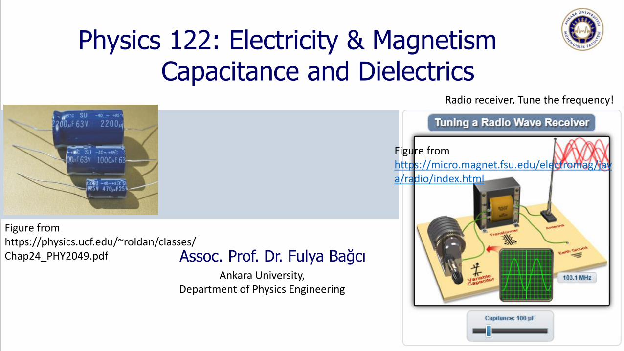
In this chapter, we introduce the first of three (Capacitors, resistors and inductors) simple circuit
elements that can be connected with wires to form an electric circuit.
Capacitors are used to tune the frequency of radio receivers, as filters in power supplies,as
energy-storing devices in electronic flash units, etc.
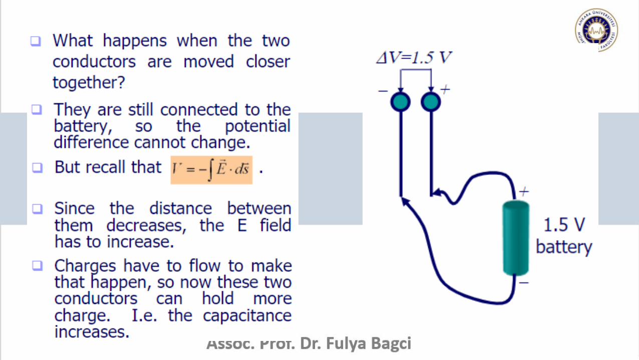
Consider two conductors as shown in Figure. Such a
combination of two conductors is called a capacitor. The
conductors are called plates. If the conductors carry
charges of equal magnitude and opposite sign, a potential
difference ΔV exists between them.
The proportionality constant depends on the shape and
separation of the conductors.
The capacitance C of a capacitor is defined as,
C is always a positive quantity. The SI unit of C is Farad.
Typical devices have capacitances ranging from microfarads to picofarads.
Figure from BOOK - Physics ForScientists And Engineers 6E BySerway And Jewett page 796
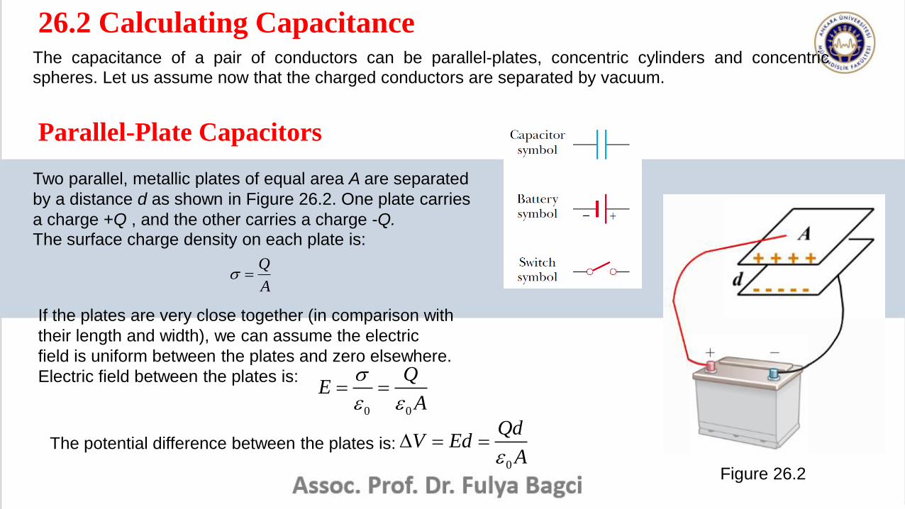
26.2 Calculating CapacitanceThe capacitance of a pair of conductors can be parallel-plates, concentric cylinders and concentric
spheres. Let us assume now that the charged conductors are separated by vacuum.
Parallel-Plate Capacitors
Two parallel, metallic plates of equal area A are separated
by a distance d as shown in Figure 26.2. One plate carries
a charge +Q , and the other carries a charge -Q.
The surface charge density on each plate is:
Figure 26.2
Q
A
If the plates are very close together (in comparison with
their length and width), we can assume the electric
field is uniform between the plates and zero elsewhere.
Electric field between the plates is:
0 0
QE
A
The potential difference between the plates is:0
QdV Ed
A
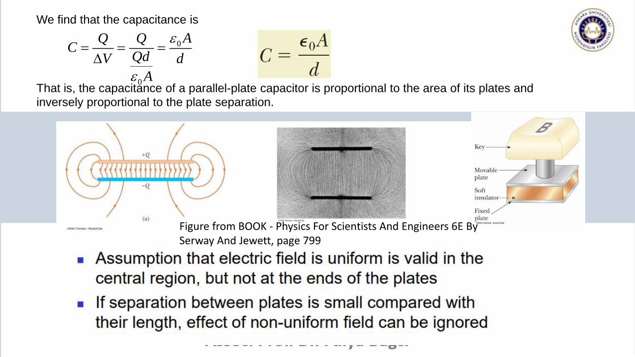
We find that the capacitance is
0
0
AQ QC
QdV d
A
That is, the capacitance of a parallel-plate capacitor is proportional to the area of its plates and
inversely proportional to the plate separation.
Figure from BOOK - Physics For Scientists And Engineers 6E BySerway And Jewett, page 799
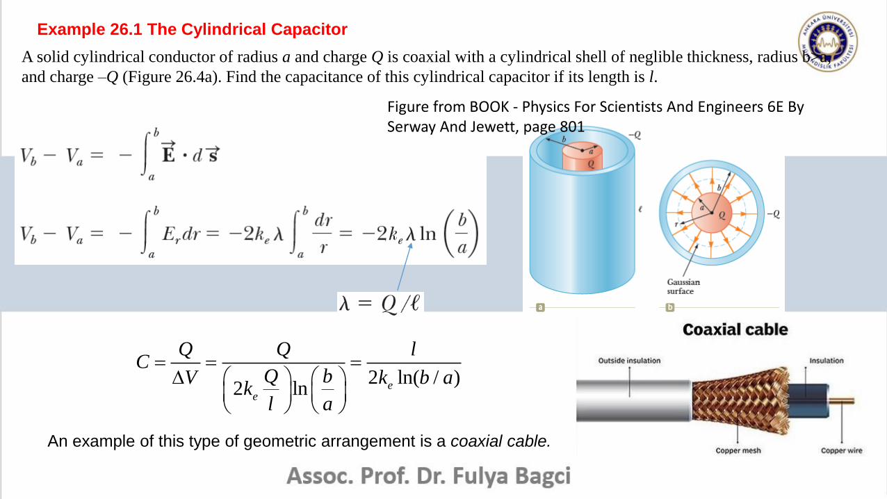
Example 26.1 The Cylindrical Capacitor
A solid cylindrical conductor of radius a and charge Q is coaxial with a cylindrical shell of neglible thickness, radius b>a,
and charge –Q (Figure 26.4a). Find the capacitance of this cylindrical capacitor if its length is l.
2 ln( / )2 ln e
e
Q Q lC
Q bV k b ak
l a
An example of this type of geometric arrangement is a coaxial cable.
Figure from BOOK - Physics For Scientists And Engineers 6E BySerway And Jewett, page 801
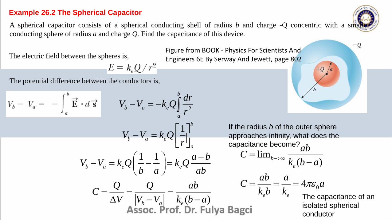
Example 26.2 The Spherical Capacitor
A spherical capacitor consists of a spherical conducting shell of radius b and charge -Q concentric with a smaller
conducting sphere of radius a and charge Q. Find the capacitance of this device.
The electric field between the spheres is,
The potential difference between the conductors is,
2
b
b a e
a
drV V k Q
r
1b
b a e
a
V V k Qr
1 1b a e e
a bV V k Q k Q
b a ab
( )b a e
Q Q abC
V V V k b a
If the radius b of the outer sphere
approaches infinity, what does the
capacitance become?
0
lim( )
4
b
e
e e
abC
k b a
ab aC a
k b k
The capacitance of an
isolated spherical
conductor
Figure from BOOK - Physics For Scientists AndEngineers 6E By Serway And Jewett, page 802
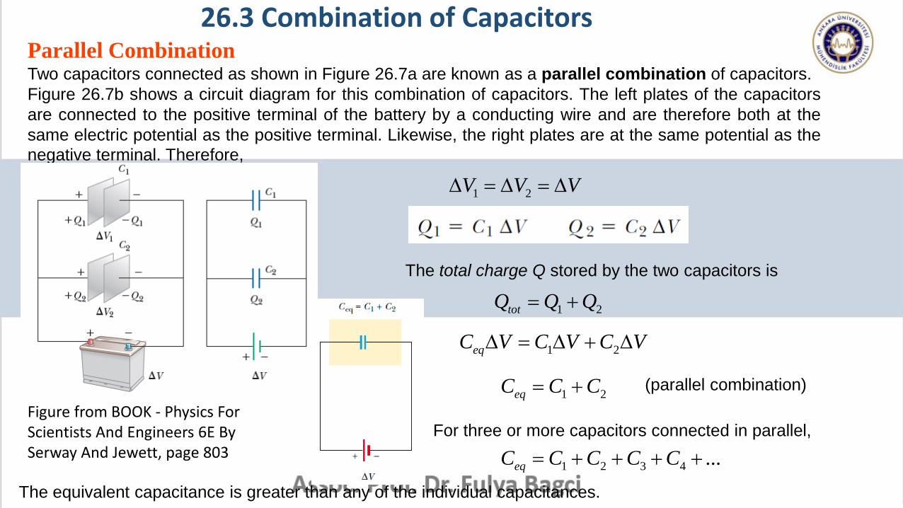
Parallel CombinationTwo capacitors connected as shown in Figure 26.7a are known as a parallel combination of capacitors.
Figure 26.7b shows a circuit diagram for this combination of capacitors. The left plates of the capacitors
are connected to the positive terminal of the battery by a conducting wire and are therefore both at the
same electric potential as the positive terminal. Likewise, the right plates are at the same potential as the
negative terminal. Therefore,
1 2V V V
1 2totQ Q Q
The total charge Q stored by the two capacitors is
1 2eqC V C V C V
1 2eqC C C (parallel combination)
For three or more capacitors connected in parallel,
1 2 3 4 ...eqC C C C C
The equivalent capacitance is greater than any of the individual capacitances.
26.3 Combination of Capacitors
Figure from BOOK - Physics ForScientists And Engineers 6E BySerway And Jewett, page 803
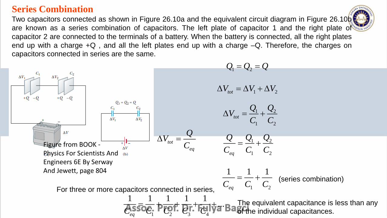
Series CombinationTwo capacitors connected as shown in Figure 26.10a and the equivalent circuit diagram in Figure 26.10b
are known as a series combination of capacitors. The left plate of capacitor 1 and the right plate of
capacitor 2 are connected to the terminals of a battery. When the battery is connected, all the right plates
end up with a charge +Q , and all the left plates end up with a charge –Q. Therefore, the charges on
capacitors connected in series are the same.
1 2Q Q Q
1 2totV V V
1 2
1 2
tot
Q QV
C C
tot
eq
QV
C 1 2
1 2eq
Q QQ
C C C
1 2
1 1 1
eqC C C (series combination)
For three or more capacitors connected in series,
1 2 3 4
1 1 1 1 1...
eqC C C C C The equivalent capacitance is less than any
of the individual capacitances.
Figure from BOOK -Physics For Scientists AndEngineers 6E By SerwayAnd Jewett, page 804
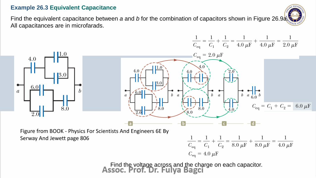
Example 26.3 Equivalent Capacitance
Find the equivalent capacitance between a and b for the combination of capacitors shown in Figure 26.9a.
All capacitances are in microfarads.
Find the voltage across and the charge on each capacitor.
Figure from BOOK - Physics For Scientists And Engineers 6E BySerway And Jewett page 806
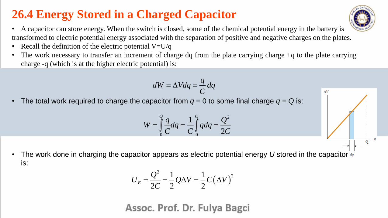
26.4 Energy Stored in a Charged Capacitor• A capacitor can store energy. When the switch is closed, some of the chemical potential energy in the battery is
transformed to electric potential energy associated with the separation of positive and negative charges on the plates.
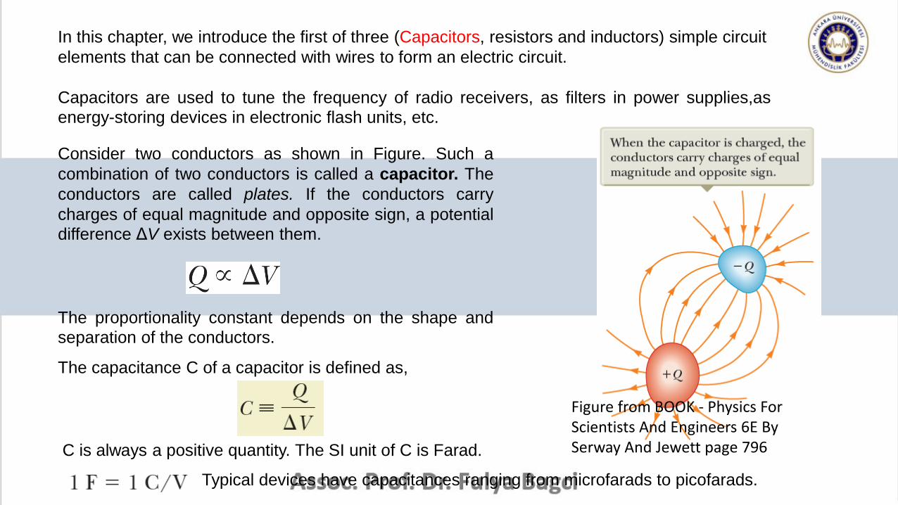
• Recall the definition of the electric potential V=U/q
• The work necessary to transfer an increment of charge dq from the plate carrying charge +q to the plate carrying
charge -q (which is at the higher electric potential) is:
qdW Vdq dq
C
2
0 0
1
2
Q Qq Q
W dq qdqC C C
2
21 1
2 2 2E
QU Q V C V
C
• The total work required to charge the capacitor from q = 0 to some final charge q = Q is:
• The work done in charging the capacitor appears as electric potential energy U stored in the capacitor
is:
• This result applies to any capacitor, regardless of its geometry.
• We see that for a given capacitance, the stored energy increases as the charge increases and as the potential
difference increases.
• In practice, there is a limit to the maximum energy (or charge) that can be stored because, at a sufficiently
great value of ΔV, discharge ultimately occurs between the plates.
• For a parallel-plate capacitor, ΔV=Ed and C=0A/d, so the the potential energy stored in a charged capacitor
becomes:
2 200
1 1( )
2 2E
AU Ed Ad E
d
• Because the volume occupied by the electric field is Ad, the energy per unit volume known as the energy
density, is:
2
0
1
2Eu E
• The energy density in any electric field is proportional to the square of the magnitude of the electric field
at a given point.
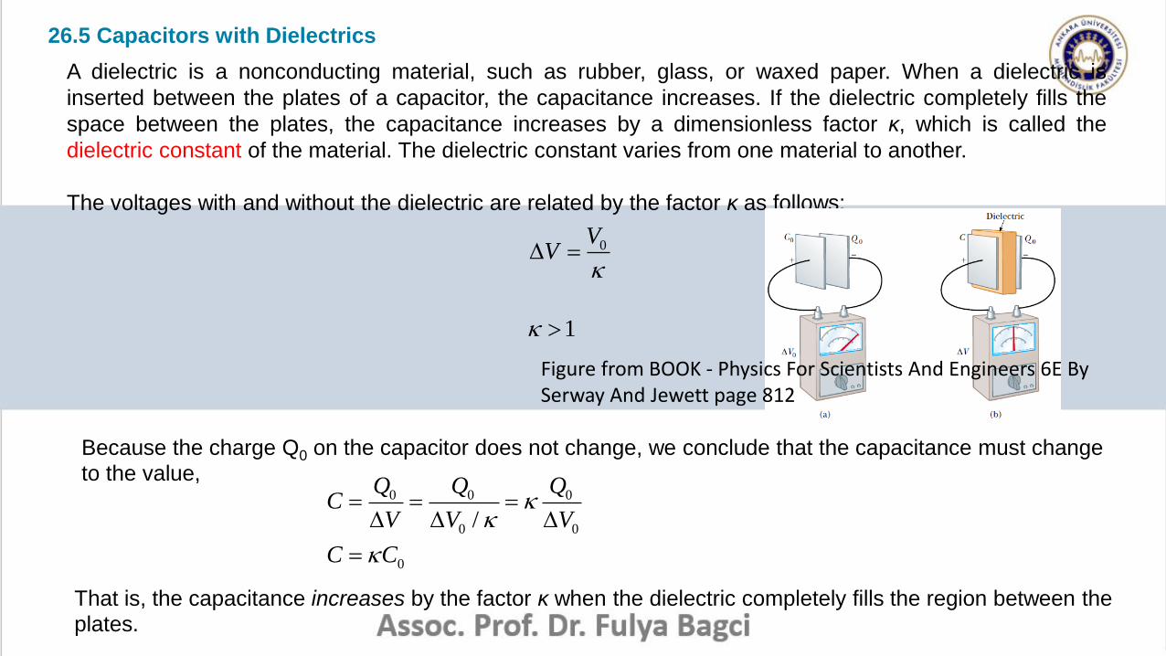
26.5 Capacitors with Dielectrics
A dielectric is a nonconducting material, such as rubber, glass, or waxed paper. When a dielectric is
inserted between the plates of a capacitor, the capacitance increases. If the dielectric completely fills the
space between the plates, the capacitance increases by a dimensionless factor κ, which is called the
dielectric constant of the material. The dielectric constant varies from one material to another.
The voltages with and without the dielectric are related by the factor κ as follows:
0VV
1
Because the charge Q0 on the capacitor does not change, we conclude that the capacitance must change
to the value,0 0 0
0 0/
Q Q QC
V V V
0C C
That is, the capacitance increases by the factor κ when the dielectric completely fills the region between the
plates.
Figure from BOOK - Physics For Scientists And Engineers 6E BySerway And Jewett page 812
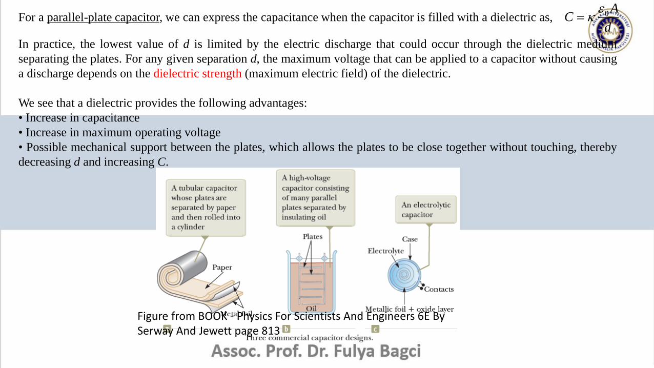
For a parallel-plate capacitor, we can express the capacitance when the capacitor is filled with a dielectric as, 0 AC
d
In practice, the lowest value of d is limited by the electric discharge that could occur through the dielectric medium
separating the plates. For any given separation d, the maximum voltage that can be applied to a capacitor without causing
a discharge depends on the dielectric strength (maximum electric field) of the dielectric.
We see that a dielectric provides the following advantages:
• Increase in capacitance
• Increase in maximum operating voltage
• Possible mechanical support between the plates, which allows the plates to be close together without touching, thereby
decreasing d and increasing C.
Figure from BOOK - Physics For Scientists And Engineers 6E BySerway And Jewett page 813
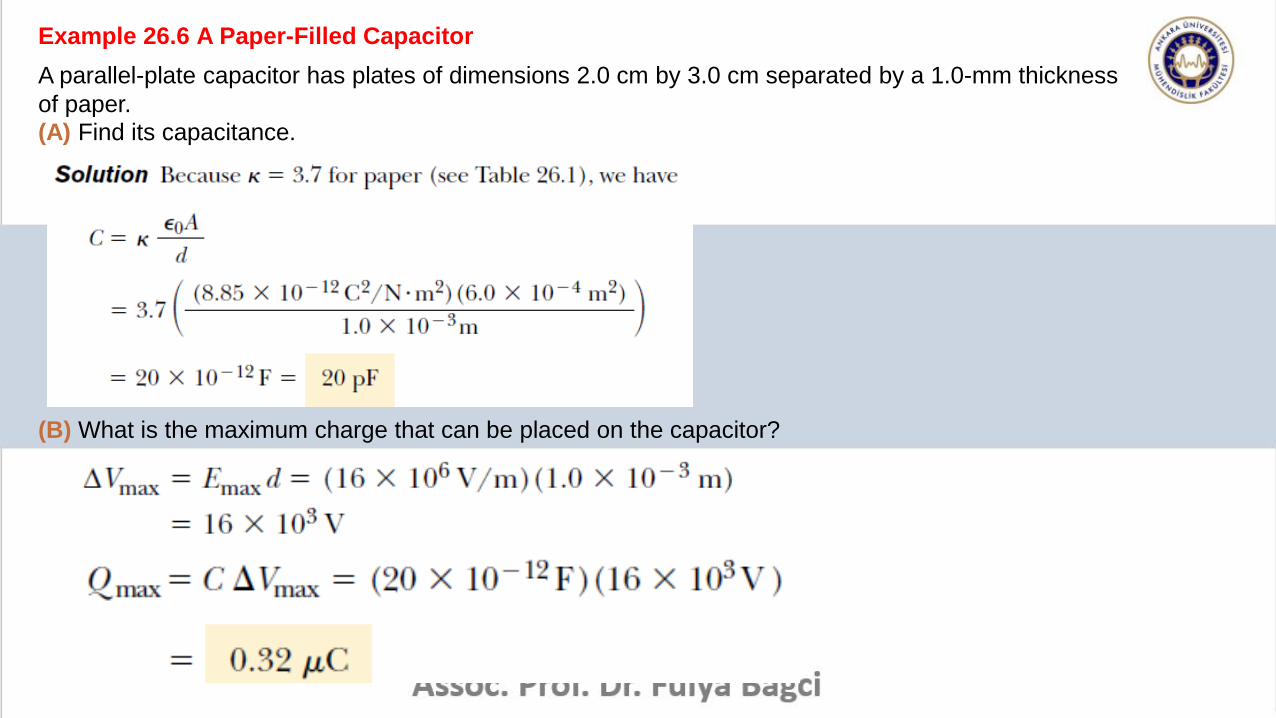
Example 26.6 A Paper-Filled Capacitor
A parallel-plate capacitor has plates of dimensions 2.0 cm by 3.0 cm separated by a 1.0-mm thickness
of paper.
(A) Find its capacitance.
(B) What is the maximum charge that can be placed on the capacitor?
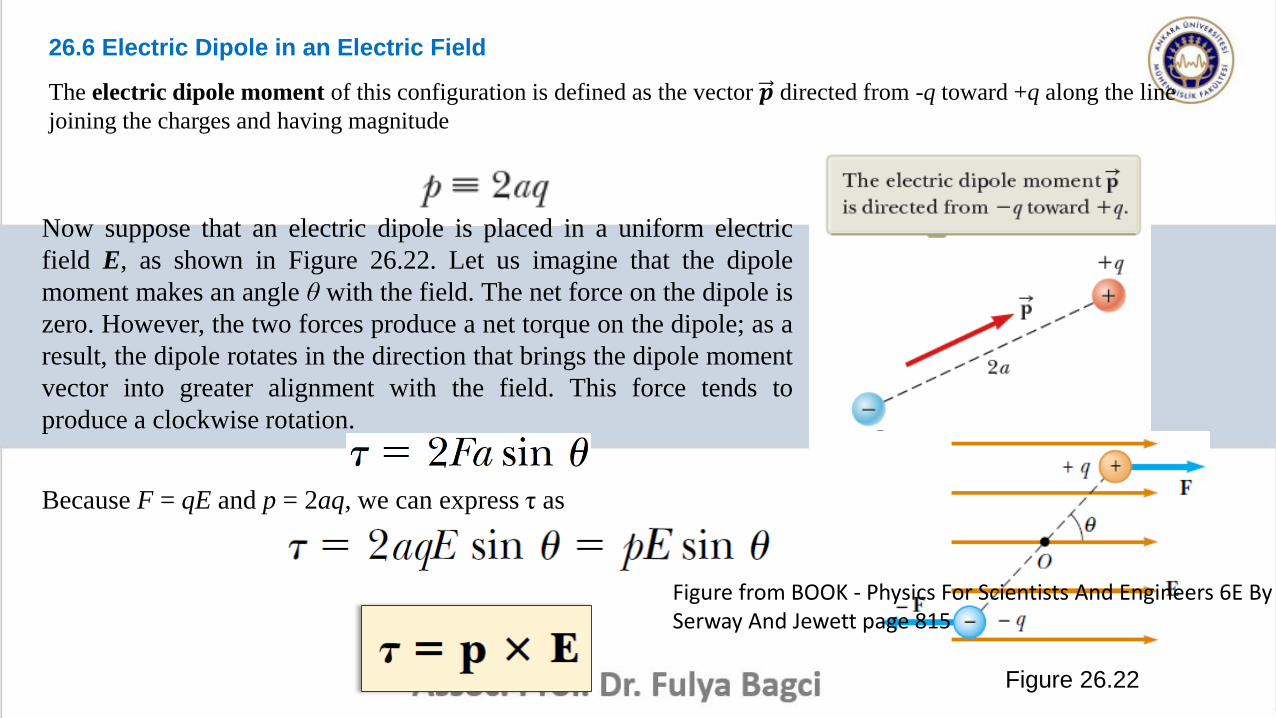
26.6 Electric Dipole in an Electric Field
The electric dipole moment of this configuration is defined as the vector 𝒑 directed from -q toward +q along the line
joining the charges and having magnitude
Now suppose that an electric dipole is placed in a uniform electric
field E, as shown in Figure 26.22. Let us imagine that the dipole
moment makes an angle θ with the field. The net force on the dipole is
zero. However, the two forces produce a net torque on the dipole; as a
result, the dipole rotates in the direction that brings the dipole moment
vector into greater alignment with the field. This force tends to
produce a clockwise rotation.
Figure 26.22
Because F = qE and p = 2aq, we can express τ as
Figure from BOOK - Physics For Scientists And Engineers 6E BySerway And Jewett page 815
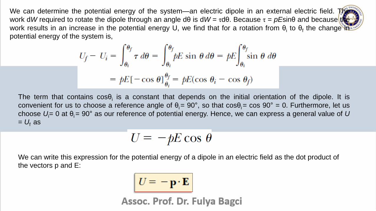
We can determine the potential energy of the system—an electric dipole in an external electric field. The
work dW required to rotate the dipole through an angle dθ is dW = τdθ. Because τ = pEsinθ and because the
work results in an increase in the potential energy U, we find that for a rotation from θi to θf the change in
potential energy of the system is,
The term that contains cosθi is a constant that depends on the initial orientation of the dipole. It is
convenient for us to choose a reference angle of θi = 90°, so that cosθi = cos 90° = 0. Furthermore, let us
choose Ui= 0 at θi = 90° as our reference of potential energy. Hence, we can express a general value of U
= Uf as
We can write this expression for the potential energy of a dipole in an electric field as the dot product of
the vectors p and E:
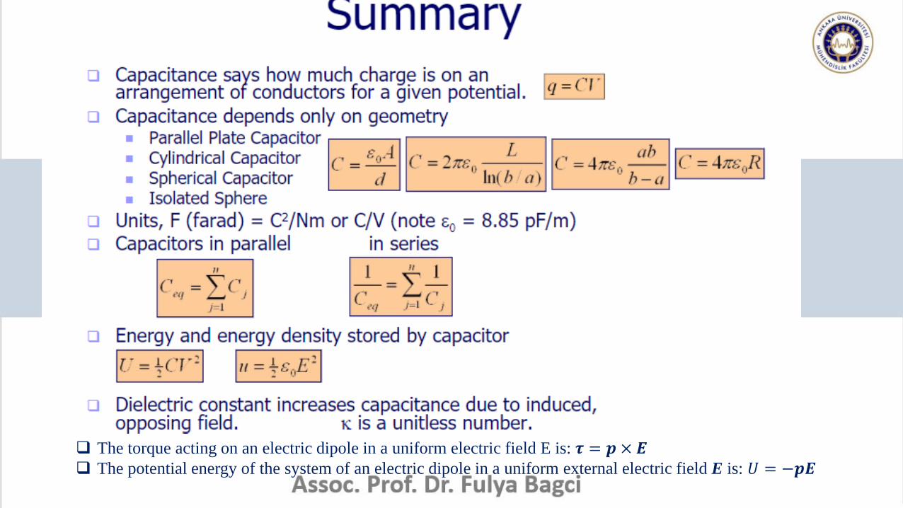
The torque acting on an electric dipole in a uniform electric field E is: 𝝉 = 𝒑 × 𝑬 The potential energy of the system of an electric dipole in a uniform external electric field E is: 𝑈 = −𝒑𝑬