Embed Size (px)
Citation preview

VALLIAMMAI ENGINEERING COLLEGE SRM NAGAR, KATTANKULATHUR – 603 203
PHYSICS PRACTICALS MANUAL BS 8161 PHYSICS LABORATORY
(First semester B.E/B.Tech. students for the Academic Year 2017-2018)
Prepared by
Dr.H.Krishnan, Dr.M.Anbuchezhiyan Dr.K.Thiruppathi, Mrs. D. Praveena, Mrs.S.Gandhimathi,
Mrs. Nithya Balaji, Mrs. R. Sasireka, Mrs. Ramya Rajan.M.P and Dr.S.Murugavel
Department of Physics
(Private circulation only)

VALLIAMMAI ENGINEERING COLLEGE
SRM NAGAR, KATTANKULATHUR – 603 203
DEPARTMENT OF PHYSICS
Instructions to the students
The following instructions must be followed by the students in their laboratory classes.
1. Students are expected to be punctual to the lab classes. If they are late, they will be considered absent for that particular session.
2. Students should strictly maintain the dress code. 3. Students must bring their observation note, record note (completed with previous experiment)
and the calculator to every lab class without fail. 4. Students are advised to come with full preparation for their lab sessions by
(i) Reading the detailed procedure of the experiment from the laboratory manual. (ii) Completion of observation note book (i.e.) Aim, Apparatus required, Formula (with
description), least count calculation, diagrams and the tabular column should be written in the observation note before entering into the laboratory.
5. Data entry in the observation note book must be by pen only. 6. Students must get attestations immediately for their observed readings. 7. Students should complete their calculations for their experiments and get it corrected on the
same day of that experiment. 8. Students who miss observation, record note they have to do the experiment once again and get
it corrected. 9. Class assessment marks for each experiment is based only on their performance in the
laboratory. 10. Record note has to be completed then and there and get corrected when the students are
coming for the next lab class. 11. Students must strictly maintain silence during lab classes. 12. If any of the students is absent for the lab class for genuine reasons, he/she will be permitted to
do the experiment during the repetition class only. 13. Students are advised to perform their experiments under safety care. 14. If any student is found causing damage to the lab equipments, he/she shall replace the same
with a new.

CONTENTS
S. No EXPERIMENTS PAGE
NO.
1 Determination of rigidity modulus – Torsion pendulum. 2
2 Determination of Young’s modulus by non-uniform bending method. 7
3 a) Determination of wavelength, and particle size using Laser.
b) Determination of acceptance angle in an optical fiber. 14
4 Determination of wavelength of mercury spectrum – Spectrometer grating
22
5 Determination of Band Gap of a semiconductor.. 28
Annexure - Data of physical constants & standard values - Viva Questions and Answers
31
Valliammai Engineering College, Department of Physics
Page | 1
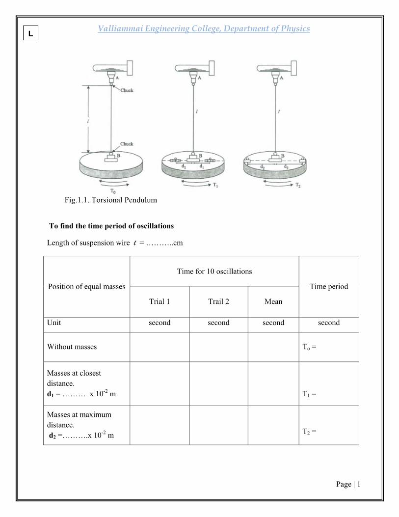
Fig.1.1. Torsional Pendulum
To find the time period of oscillations
Length of suspension wire l = ………..cm
Position of equal masses
Time for 10 oscillations
Time period Trial 1
Trail 2
Mean
Unit second second second second
Without masses
To =
Masses at closest distance. d1 = ……… x 10-2 m
T1 =
Masses at maximum distance. d2 =……….x 10-2 m
T2 =
L

Valliammai Engineering College, Department of Physics
Page | 2
1. DETERMINATION OF RIGIDITY MODULUS –TORSIONAL PENDULUM
AIM
To determine the moment of inertia of a given disc by Torsional oscillations and The rigidity modulus of the material of the suspension wire.
APPARATUS Torsional pendulum, Stop clock, Meter scale, Two symmetrical mass, Screw gauge.
PRINCIPLE
The suspension wire is twisted by the circular disc fixed at the bottom of the wire and the wire undergoes shearing strainwhich leads to torsional oscillations. The angular acceleration of the disc is proportional to its angular displacement and is always directed towards its mean position and the motion of the disc is simple harmonic.
FORMULA Moment of inertia of the circular disc,
I = kg.m2
Rigidity modulus of the wire,
n = N/ m2
Symbol Explanation unit
m mass of one cylinder placed on the disc(100 gm) kg
d1 Closest distance ( minimum) between suspension wire and the centre of mass of the cylinder m
d2 Farthest distance ( maximum) between suspension wire and the centre of mass of the cylinder m
T0 Period of oscillation without any mass on the disc s
T1 Period of oscillation when equal masses are placed on the disc at a distance d1
s
T2 Period of oscillation when equal masses are placed on the disc at a distance d2
s
l length of the suspension wire m r Radius of the wire m
R

Valliammai Engineering College, Department of Physics
Page | 3
LEAST COUNT OF THE SCREW GAUGE:
Distance moved by the head scale on the pitch scale. Pitch = Number of rotations given to the head scale. Pitch Least count (LC) = Total number of divisions on the head scale Pitch = 5 mm/ 5 = 1 mm LC = 1 mm/ 100 = 0.01 mm.
To find the radius (r) of the specimen using screw gauge
LC = 0.01 mm Z.E = …..div
Z.C =……mm
S. No. PSR HSC HSR= HSC x LC
Observed Reading = PSR
+ HSR
Correct Reading = OR
+ ZC Unit mm div mm mm mm
Mean (d) =-------------------------- x 10-3 m
Radius of the specimen wire (r) = d/2 = ……. x 10-3 m
L

Valliammai Engineering College, Department of Physics
Page | 4
PROCEDURE
• When the suspension wire is twisted by the circular disc fixed at the bottom of the wire, the wire undergoes shearing strain. This is called torsion. Because of this torsion, the disc executes oscillation called torsional oscillation.
• The Torsional pendulum consists of a circular disc suspended by a thin suspended wire, as shown in Fig. (1.1), whose rigidity modulus is to be noted. The top end of the wire is fixed by a chuck. The circular disc is attached to the other end of the wire.
Calculation of T0
• Adjust the wire so that its length is fixed value say 50 cm. Make a vertical
chalk mark on the disc when it is rest as a reference. By making a small twist to the circular disc, set up Torsional oscillations. After the first few oscillations, just as the mark on the disc passes the equilibrium positions, a stop clock is started. The time taken for 10 complete oscillations is noted. The experiments are repeated for second trial and mean value is calculated. The mean value of the period is noted as T0.
Calculation of T1 • The two identical cylindrical masses are placed at equal distance on either
side of the central chuck as close as possible. The distance d1 is measured between the wire and the centre of the cylindrical mass. By twisting the disc, the time taken for 10 complete oscillations is noted. The mean value of the time period is noted as T1.
Calculation of T2 • The identical masses are arranged symmetrically as far away from the
axis of the rotation as possible. The distance d2 is measured between the centre of the cylindrical mass of the time taken for 10 complete oscillations is calculated in the same manner as that of the calculation of T0 and T1.
Calculation of Moment Of Inertia and Rigidity Modulus
• The mean value of the radius and length of the wire is measured accurately by
a screw gauge and meter scale respectively. The moment of the inertia of the circular disc and the rigidity modulus of the suspension wire are calculated by substituting the values in the equations respectively.
• Moment of Inertia can also be determined theoretically I = MR2, where M= Mass of the Disc, R= radius of the Disc.
R

Valliammai Engineering College, Department of Physics
Page | 5
CALCULATION
Mean radius of the wire r = m
Length of the wire l = m
Mass of the identical cylinder m = kg
Closest distance between suspension wire & the centre of symmetrical mass d1 = m Farthest distance between suspension wire& the centre of symmetrical mass d2 = m Period of oscillations (without masses) T0 = sec Period of oscillations with masses at ‘d1’ distance T1 = sec Period of oscillations with masses at ‘d2’ distance T2 = sec
The moment of inertia of the circular disc,
I = kg.m2
I = kg/m2
Rigidity modulus of them wire,
η = N/ m2
η = N/m2
L
Valliammai Engineering College, Department of Physics
Page | 6
RESULT
(i) Moment of inertia of the circular disc I = _______ kg m²
(ii) Rigidity modulus of the given wire η = N/m2
R

Valliammai Engineering College, Department of Physics
Page | 7
Figure 2.1 Young’s modulus of the material – Non-uniform bending
DETERMINATION OF LEAST COUNT OF TRAVELLING MICROSCOPE
Least count = 1 MSD – 1 VSD 20 MSD = 1 cm Value of 1 MSD =
cm = 0.05 cm
Number of Vernier Scale Division = 50 50 VSD = 49 MSD 1 VSD = MSD = x 0.05 = 0.049 LC = 0.05 – 0.049 = 0.001 cm LC = 0.001 cm
To find depression ‘y’
Distance between two knife edges (l) = _____ x 10 -2 m
TR = MSR + (VSC x LC)
M = -------------------- x 10-3 kg L.C = 0.001 cm
S.No Load
Microscope Readings
Mean
DepressionY for M
kg
Loading Unloading MSR
VSC
TR
MSR
VSC
TR
Unit x 10-3kg cm div cm cm div cm cm cm 1 W 2 W+50 3 W+100 4 W+150 5 W+200
Mean (y) = ------- x 10-2 m
L

Valliammai Engineering College, Department of Physics
Page | 8
2. YOUNG’S MODULUS OF THE MATERIAL – NON-UNIFORM BENDING
AIM To determine the young’s modulus of the material of a uniform bar by non uniform bending method.
APPARATUS REQUIRED
Traveling microscope, Weight hanger with slotted weights, Two knife edges, Pin, Wooden bar,
Vernier caliper, Screw gauge.
PRINCIPLE
When a beam symmetrically supported on two knife edge is loaded at its centre, the bent beam would not form an arc of circle. This type of bending is called non uniform bending. The maximum depression is produced at its mid point.
FORMULA
The Young’s Modulus of the beam,
4
Symbol Explanation Unit
M Load applied kg l Distance between the two knife edges m b Breadth of the beam (meter scale) m d Thickness of the beam (meter scale) m
y Depression produced for ‘M’ kg of load m
g Acceleration due to gravity ms-2
R

Valliammai Engineering College, Department of Physics
Page | 9
To find the thickness (d) of the beam using screw gauge
LC = 0.01 mm Z.E = ….. div
Z.C = …… mm
S. No. PSR HSC HSR = HSC x LC Observed Reading = PSR +HSR
Correct Reading = OR + ZC
Unit mm div mm mm mm
Mean (d) = ------------------------- x10-3 m
To find the breadth (b) of the beam using Vernier Calipers
LC = 0.01 cm Z.E = ….. div
Z.C = …… cm
S. No. MSR VSC VSR = VSC x LC Observed Reading = MSR +VSR
Correct Reading = OR +ZC
Unit cm div cm cm cm
Mean (b) =-------------------------- x10-2 m
L
Valliammai Engineering College, Department of Physics
Page | 10
PROCEDURE
The weight of the hanger is taken as the dead load ‘w’. The wooden bar is brought to elastic mood by loading and unloading it, a number of times with slotted weights. With the dead load w suspended from the midpoint, the microscope is adjusted such that the horizontal cross-wire coincides with the image of the tip of the pin. The reading in the vertical scale is taken. The experiment is repeated by adding weights in steps of 50 gm each. Every time the microscope is adjusted and the vertical scale reading is taken. Then the load is decreased in the same steps and the readings are taken. From the readings, the mean depression of the mid-point for a given load can be found. The length of the wooden bar between the knife edges is measured (l).
The wooden bar is removed and its mean breadth ‘b’ and mean thickness ‘d’are determined with a Vernier caliper and a screw gauge respectively. From the observations, Young modulus of the material of the beam is calculated by using the given formula.
R

Valliammai Engineering College, Department of Physics
Page | 11
CALCULATION
Acceleration due to gravity g = 9.8 ms-2
Distance between the two knife edges l = ………. m
Breadth of the beam b = ………… m
Thickness of the beam d = ………….. m
Depression produced for ‘M’ kg of load y = ………….. m
Load to calculate depression M = ………….. kg
The Young’s modulus of the given material of the beam
4
RESULT
The Young’s Modulus of the given wooden bar
E = …………… newton/meter2
L
Valliammai Engineering College, Department of Physics
Page | 12
R
Valliammai Engineering College, Department of Physics
Page | 13
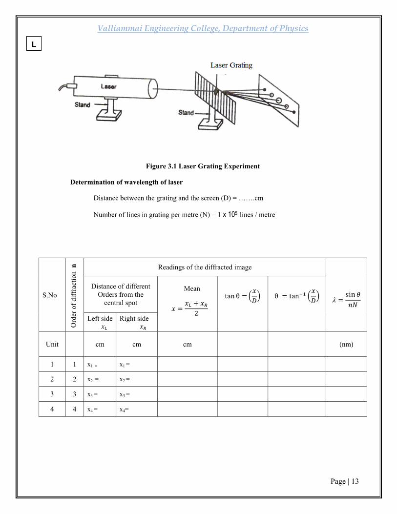
Figure 3.1 Laser Grating Experiment
Determination of wavelength of laser
Distance between the grating and the screen (D) = …….cm
Number of lines in grating per metre (N) = 1 x 10⁵ lines / metre
S.No
Ord
er o
f diff
ract
ion
n
Readings of the diffracted image
λsin
Distance of different Orders from the
central spot 2
Mean tan θ
θ tan
Left side
Right side
Unit cm cm cm (nm)
1 1 x1 = x1 =
2 2 x2 = x2 =
3 3 x3 = x3 =
4 4 x4 = x4=
L

Valliammai Engineering College, Department of Physics
Page | 14
3. (a) DETERMINATION OF WAVELENGTH OF THE GIVEN LASER
AIM:
To determine the wavelength of the given laser using grating.
APPARATUS REQUIRED
Diode laser, grating, screen and scale.
PRINCIPLE
The laser light is exposed to the grating and diffraction takes place.
FORMULA
(1) Wavelength of the given laser
λ meter
Symbol Explanation Unit θ Angle of diffraction degree N Order of diffraction - N Number of lines per meter in the grating lines/m
PROCEDURE:
Diode laser is kept horizontally and switched on (care should be taken). The grating is held normal to the laser beam. This is done by adjusting the grating in such a way that the reflected laser beam coincides with the beam coming out of the laser. As shown in the Fig.3.1 After adjusting for normal incidence, the laser light is exposed to the grating and it is diffracted by it. On the other side of the grating on the screen, the diffracted laser spots are seen. The distances of different orders from the centre spot (x) are measured. The distance between the grating and screen (D) is measured. Using the formula ‘θ’ is calculated. The wavelength of the laser light source is calculated using the given formula.
λ = θ metre
The number of lines in the grating is assumed as ≈ 1 x 10⁵ lines per metre.
R

Valliammai Engineering College, Department of Physics
Page | 15
Figure 3.2. Particle size determination by Laser
Particle size determination
S.No Distance between screen and glass plate (D)
Order of diffraction
n
Distance between the central bright point and
nth fringe Xn
Particle Size d = λ
Unit cm cm cm
1
1
2
2
1
2
Mean d =
L

Valliammai Engineering College, Department of Physics
Page | 16
PARTICLE SIZE DETERMINATION USING LASER
AIM
To determine the size of the given micro particles (lycopodium powder) using laser.
APPARATUS REQUIRED
Diode laser, fine micro particles having nearly same size, glass plate, screen, metre scale
FORMULA
Particle size (diameter) d is given by
Symbol Explanation Units
n Order of diffraction - λ Wavelength of laser light used metre D Distance between glass plate and the screen. metre xn Distance between central bright spot and the nth ring metre
PROCEDURE
A glass plate is taken and a fine powder of particle size in the range of micrometer is sprinkled on the glass plate. This glass plate is kept between laser light and screen. The experimental is shown in the Fig.3.2. Now laser beam gets diffracted by the particles present in the glass plate. By adjusting the distance between the glass plate and the screen, (D) a circular fringe pattern is seen on the screen and the distance between the central bright point and nth fringe xn for various orders of diffraction is measured.
Using the formula, the particle size is determined. The experiment is repeated for different D values.
R

Valliammai Engineering College, Department of Physics
Page | 17
Figure 3.3. Experimental setup for acceptance angle
To determine acceptance angle
S.No
Distance from the fiber end to circular
image ‘d’
Radius of the circular image
‘r’
Acceptance angle
180
Unit cm mm deg. 1
2
3
4
L

Valliammai Engineering College, Department of Physics
Page | 18
(b) DETERMINATION OF ACCEPTANCE ANGLE IN AN OPTICAL FIBRE
AIM
To determine acceptance angle of an optical fiber.
APPARATUS REQUIRED
Laser for optical fiber light source, optical fiber, optical fiber connectors and Numerical aperture Jig.
PRINCIPLE
The principle behind the transmission of light waves in an optical fiber is total internal reflection.
FORMULA
Acceptance angle deg
Symbol Explanation Unit
r Radius of the circular image metre d Distance from fibre end to circular image metre
PROCEDURE
Using laser, we can find the acceptance angle of the fiber optic cable. The given laser source is connected to the optical fiber cable. The other end is exposed to the air medium in the dark place. The emerging light is exposed on a plain paper.
Now, we get illuminated circular patch on the screen.Fig.3.3 shows the experimental setup for acceptance angle measure. The distance from the fiber end to circular image (d) is measured using meter scale. The radius of the circular image is also measured. Thus the acceptance angle is calculated
R

Valliammai Engineering College, Department of Physics
Page | 19
CALCULATION
(i) Wavelength of the laser source,
λ sin metre
(ii) The size of the particle,
(iii) Acceptance angle,
deg
RESULTS i) Wavelength of the given source λ = ------------------- metre.
ii) The size of the particle d = ___________ m
iii) Acceptance angle θa = ___________ degree.
L

Valliammai Engineering College, Department of Physics
Page | 20
R

Valliammai Engineering College, Department of Physics
Page | 21
Figure 4.1.To set for normal incidence position Figure 4.2. Diffracted ray from grating
DETERMINATION OF LEAST COUNT
2MSD = 1°
1MSD = 1/2° = 0.5° = 30′
LC = 1 MSD – 1 VSD
Number of divisions in vernier scale = 30
30 VSD = 29 MSD
1 VSD = 29/30 x MSD = 29/30′ x30′ =29′
LC = 30′ – 29′
LC = 1′ (One minute)
L

Valliammai Engineering College, Department of Physics
Page | 22
4. SPECTROMETER - DETERMINATION OF WAVELENGTH OF MERCURY SPECTRUM
AIM
To determine the wavelength of the mercury (Hg) spectrum using the plane transmission grating.
APPARATUS REQUIRED
Spectrometer, Sodium vapour lamp, Plane transmission grating, spirit level, Mercury vapour lamp, and reading lens.
PRINCIPLE A plane sheet of transparent material on which a large number of equidistant opaque rulings are made with a diamond point forms grating. The space between the rulings and transparent area constitute a parallel slit. When light passes through such a grating, diffraction takes place. Angle of diffraction depends upon the wavelength of the light and number of lines per metre on the grating. So the number of lines per metre in grating and wavelength of the source can be calculated.
FORMULA
The wavelength of the spectral lines of mercury spectrum
Symbol Explanation Unit θ Angle of diffraction degN Number of lines/ metre lines/ metre n Order of spectrum no unit
R

Valliammai Engineering College, Department of Physics
Page | 23
To
dete
rmin
e th
e w
avel
engt
h(λ)
of t
he p
rom
inen
t lin
es o
f the
mer
cury
spec
trum
Leas
t cou
nt =
1’
O
rder
of t
he sp
ectru
m n
= 1
N
= …
……
……
……
……
……
….li
nes/
met
er
TR
= M
SR +
(V
SC x
LC
)
met
er
Mea
n an
gle
of
diff
ract
ion
θ deg.
Mea
n
2θ
deg.
Diff
eren
ce b
etw
een
Ver
nier
A
and
V
erni
er B
2θ
=B1∼
B2
deg.
2θ
=A1∼
A2
deg.
Rea
ding
s for
diff
ract
ed im
age
Rig
ht si
de V
erni
er B
(B
2)
TR
deg.
VSC
div.
MSR
deg.
Ver
nier
A
(A2)
TR
deg.
VSC
div.
MSR
deg.
Left
Sid
e
Ver
nier
B
(B1)
TR
deg.
VSC
div.
MSR
deg.
Ver
nier
A
(A1)
TR
deg.
VSC
div.
MSR
deg.
Sp
ectra
l lin
es
(col
ours
)
Vio
let
Blu
e
Gre
en
Yel
low
Red
L
Valliammai Engineering College, Department of Physics
Page | 24
PROCEDURE
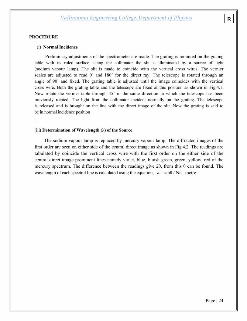
(i) Normal Incidence
Preliminary adjustments of the spectrometer are made. The grating is mounted on the grating table with its ruled surface facing the collimator the slit is illuminated by a source of light (sodium vapour lamp). The slit is made to coincide with the vertical cross wires. The vernier scales are adjusted to read 0˚ and 180˚ for the direct ray. The telescope is rotated through an angle of 90˚ and fixed. The grating table is adjusted until the image coincides with the vertical cross wire. Both the grating table and the telescope are fixed at this position as shown in Fig.4.1. Now rotate the vernier table through 45˚ in the same direction in which the telescope has been previously rotated. The light from the collimator incident normally on the grating. The telescope is released and is brought on the line with the direct image of the slit. Now the grating is said to be in normal incidence position .
(iii) Determination of Wavelength (λ) of the Source
The sodium vapour lamp is replaced by mercury vapour lamp. The diffracted images of the first order are seen on either side of the central direct image as shown in Fig.4.2. The readings are tabulated by coincide the vertical cross wire with the first order on the either side of the central direct image prominent lines namely violet, blue, bluish green, green, yellow, red of the mercury spectrum. The difference between the readings give 2θ, from this θ can be found. The wavelength of each spectral line is calculated using the equation, λ = sinθ / Nn metre.
R

Valliammai Engineering College, Department of Physics
Page | 25
CALCULATION
Order of the spectrum n = 1
1. The wavelength of the spectral lines of mercury spectrum,
Wavelength for violet,
λv =……………….Å
Wavelength for blue λB =……………….Å
Wavelength for green λG=……………… Å
L

Valliammai Engineering College, Department of Physics
Page | 26
Wavelength for yellow λY=……………………….Å Wavelength for red λR =……………….Å
RESULT
(i) Wavelength of various spectral lines
S.No Colour of the spectrum
wavelength Å
1 Violet
2 Blue
3 Green
4 Yellow 5 Red
R

Valliammai Engineering College, Department of Physics
Page | 27
Fig.5.1. Circuit for band gap determination Fig.5.2. Variation of current with inverse temperature in a reverse biased pn -diode
L

Valliammai Engineering College, Department of Physics
Page | 28
5. DETERMINATION OF BAND GAP OF A SEMICONDUCTOR
AIM
To determine the band gap energy of a semiconductor by varying the temperature
APPARATUS REQUIRED
Semiconductor diode, Heating arrangement to heat the diode, Ammeter, Voltmeter, thermometer.
PRINCIPLE
For a semiconductor diode at 0K the valence band is completely filled and the conduction band is empty and it behaves as an insulator. If the temperature is increased, some of the valence electrons gains thermal energy greater than the forbidden energy (Eg) and it moves to conduction band, which constitutes some current to flow through the semiconductor diode.
FORMULA
Band gap energy Eg = 0.198 x Slope eV
Slope = log Is / (1000/T)
Symbol Explanation Unit
Is Saturation current μA
T Absolute temperature kelvin
PROCEDURE
• The circuit is given as shown in Fig.(5.1) • The semiconductor diode and the thermometer is immersed in the water or oil
bath, in such a way that the thermometer is kept nearby the diode. • The power supply is kept constant (2Volts). • The heating mantle is switched ON and the oil bath is heated up to 70°C. • Now the heating mantle is switched OFF and the oil bath is allowed to cool
slowly. • For every five degree fall of temperature the micro ammeter the reading Is is noted.
R

Valliammai Engineering College, Department of Physics
Page | 29
S.No Temperature
Temperature 1000 /T Is
Log Is
unit °C K K-1 x 10 -6 A
1
2
3
4
5
6
7
8
9
10
L

Valliammai Engineering College, Department of Physics
Page | 30
• A graph is plotted taking 1000/T along x axis and log Is along negative y axis (Fig.1.2), (Since Is in the order of micro-ampere, log Is value will come in negative).
• A straight line obtained as shown in model graph • By finding the slope of the straight line, the band gap energy can be calculated
using the given formula.
CALCULATION
Eg= 0.198 x Slope eV
Eg = 0.198 x log Is / (1000/ T) eV
E
g = eV RESULT The band gap energy of the given diode is Eg= eV.
R

Valliammai Engineering College, Department of Physics
Page | 31
DATA OF PHYSICAL CONSTANTS & STANDARD VALUES
S.No. Physical Constants Symbol Value in SI Unit
1 Velocity of light C 3 x 10⁸ m/s
2 Acceleration due to gravity g 9.8 m/s2
3 Planck’s constant h 6.625 x 10⁻³⁴ Js
4 Charge of an electron e 1.69 x 10⁻¹⁹ C
5 Avogadro number NA 6.023 x 1026 atoms/ k mole
6 Boltzmann constant k 1.38 x 10⁻²³ J/K
7 Young’s modulus of the wooden beam E 1 x 10¹⁰ Nm-2
8 Young’s modulus of the teak wooden beam
E 1.7 x 10¹⁰ Nm-2
9 Wavelength of sodium vapour lamp λ D1 = 5890 Å,
D2 = 5896 Å
10 Wavelength of mercury vapour lamp
λv
λB
λG
λYI
λR
4047 Å
4358 Å
5461 Å
5770 Å
6234 Å
L

Valliammai Engineering College, Department of Physics
Page | 32
VIVA QUESTIONS AND ANSWERS
RIGIDITY MODULUS- TORSIONAL PENDULUM
1. What is torsional pendulum? A body suspended from a rigid support by mens of a long and thin
elastic wire is called torsional pendulum.
2. What is the type of oscillation?
This is of simple harmonic oscillation type.
3.How will you determine the rigidity of fluids?
As fluids do not have a shape of their own, hence they do not posses rigidity. Hence there is no question of determining it.
YOUNGS MODULUS NON-UNIFORM BENDING 1. What is young’s modulus?
Young’s modulus is defined as the ratio of longitudinal stress to longitudinal strain. 2. What is a beam?
When the lengths of the rod of uniform cross section is very large compared to its breadth such that the shearing stress over any section of the rod can be neglected, the rod is called beam. 3. How are longitudinal strain and stress produced in your experiment?
Due to depression, the upper or the concave side of the beam becomes smaller than the lower or the convex side of the beam. As a result, longitudinal strain is produced. The change in wave length of the beam. These forces will give rise to longitudinal stress. 4. Which dimension- breath, thickness or length of the bar-should be measured very careful and why?
The thickness of the bar should be measured very carefully since its magnitude is small and it occurs in the expression ‘E’ in the power of three. An inaccuracy in the measurement of the thickness will produce the greatest proportional error in ‘E’. 5. Why do you place the beam symmetrically on the knife edges?
To keep the reaction at the knife edges equal in conformity with the theory.
R
Valliammai Engineering College, Department of Physics
Page | 33
LASER PARAMETERS 1. Define LASER?
The term LASER stands for Light Amplification by Stimulated Emission of Radiation. It is a device which produces a powerful, monochromatic collimated beam of light in which the waves are coherent.
2. What is meant by active material in laser?
The material in which the population inversion is achieved is called active material. 3. What is semi conductor diode laser?
Semiconductor diode laser is a specially fabricated pn junction diode. It emits laser light when it is forward biased.
4. What are the characteristic of laser radiation?
Laser radiations have high intensity, high coherence, monochromatic and high directionality
with less divergence.
5. What is stimulated emission?
The process of forced emission of photons caused by incident photons is called stimulated emission
6. Define acceptance angle
The maximum with which a ray of light can enter through one end of the fiber and still be totally internally reflected is called acceptance angle of the fiber. 7. What is the principle used in fiber optic communication system?
The principle behind the transmission of light waves in an optical fiber is total internal reflection
BAND GAP OF A SEMICONDUCTOR
1.Define Fermi level
Fermi level is that state at which the probability of electron occupation is ½ at any temperature above 0K and also it is the level of maximum energy of the filled states at 0K.
L

Valliammai Engineering College, Department of Physics
Page | 34
2.What are intrinsic and extrinsic semiconductors?
Instrinsic semiconductors are semiconductors in pure form. A semiconducting material in charge carriers originate from impurity atoms added to the material is called extrinsic semiconductor.
SPECTROMETER GRATING
1. What is the use of collimator and telescope?
A collimator is a device that narrows a beam of particles or waves. A telescope is an instrument that aids in the observation of remote objects by collecting electromagnetic radiation (such as visible light).
2. What is plane transmission diffraction grating?
A plane transmission diffraction grating is an optically plane parallel glass plate on which equidistant, extremely close grooves are made by ruling with a diamond point. 3. In our experiment. What class of diffraction does occur and how?
Fraunhofer class of diffraction occurs. Since the spectrometer is focused for parallel rays, the source and the image are effectively at infinite distances from the grating. 4. How are the commercial gratings are made?
A commercial grating is made by pouring properly diluted cellulose acetate on the actual grating and drying it to a thin strong film. The film is detached from the original grating and is mounted between two glass plates. A commercial grating is called replica grating. In our experiment we use plane type replica grating.
R