Embed Size (px)
Citation preview
PHYSICS PRACTICALS MANUAL GE6163 PHYSICS LABORATORYI
(First semester B.E/B.Tech. students for the Academic Year 2016-2017)
www.alls
yllab
us.co
m
www.allsyllabus.com
vtu.allsyllabus.com
CONTENTS
S. No EXPERIMENTS PAGE
NO.
1 a) Determination of wavelength and particle size of the diode
laser. b) Determination of Acceptance angle in an Optical Fiber.
2
2 Determination of velocity of sound and compressibility of liquid- Ultrasonic interferometer 10
3 Determination of wavelength of prominent lines of Hg spectrum - spectrometer grating.
16
4 Determination of thermal conductivity of a bad conductor – Lee’s Disc method.
22
5 Determination of Young’s modulus by non-uniform bending method
29
Annexure - Data of physical constants & standard values - Viva Questions & Answers
33
www.alls
yllab
us.co
m
www.allsyllabus.com
vtu.allsyllabus.com
Page | 1
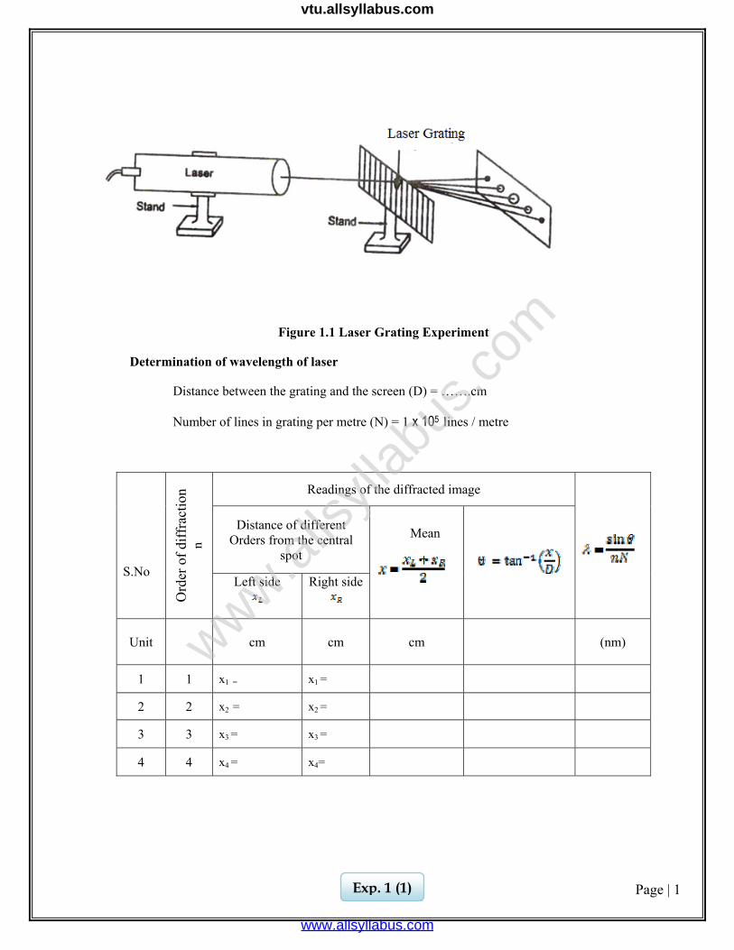
Figure 1.1 Laser Grating Experiment
Determination of wavelength of laser
Distance between the grating and the screen (D) = …….cm
Number of lines in grating per metre (N) = 1 x 10⁵ lines / metre
S.No
Ord
er o
f diff
ract
ion
n
Readings of the diffracted image
Distance of different Orders from the central
spot
Mean
Left side
Right side
Unit cm cm cm (nm)
1 1 x1 = x1 =
2 2 x2 = x2 =
3 3 x3 = x3 =
4 4 x4 = x4=
Exp. 1 (1)
www.alls
yllab
us.co
m
www.allsyllabus.com
vtu.allsyllabus.com
Page | 2
Ex. No. : Date: 1. (a) DETERMINATION OF WAVELENGTH OF THE GIVEN LASER
AIM:
To determine the wavelength of the given laser using grating.
APPARATUS REQUIRED
Diode laser, grating, screen, paper and pencil.
PRINCIPLE
The laser light is exposed to the grating and diffraction takes place.
FORMULA
(1) Wavelength of the given laser
metre
Symbol Explanation Unit θ Angle of diffraction degree n Order of diffraction - N Number of lines per metre in the grating lines/m
PROCEDURE:
Diode laser is kept horizontally and switched on (care should be taken). The grating is held normal to the laser beam. This is done by adjusting the grating in such a way that the reflected laser beam coincides with the beam coming out of the laser. After adjusting for normal incidence, the laser light is exposed to the grating and it is diffracted by it. On the other side of the grating on the screen, the diffracted laser spots are seen. The distances of different orders from the centre spot (x) are measured. The distance between the grating and screen (D) is measured. Using the formula ‘θ’ is calculated. The wavelength of the laser light source is calculated using the given formula.
λ = metre
The number of lines in the grating is assumed as ≈ 1 x 10⁵ lines per metre.
Exp. 1 (2)
www.alls
yllab
us.co
m
www.allsyllabus.com
vtu.allsyllabus.com
Page | 3
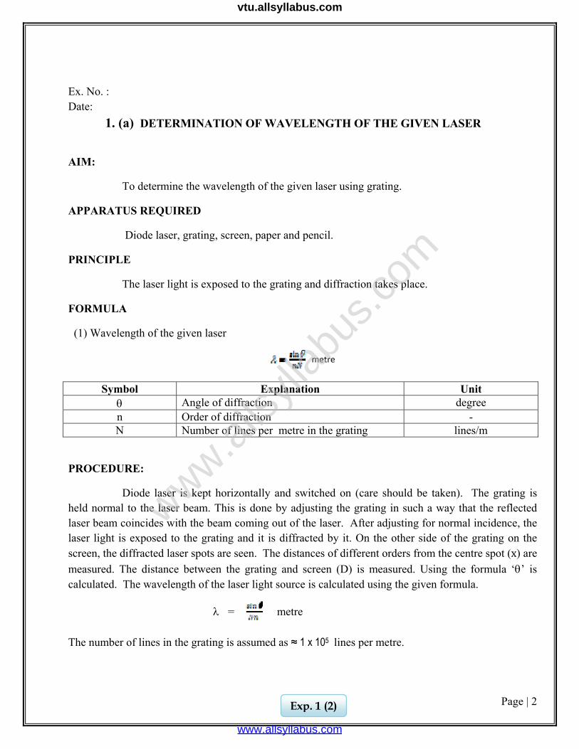
Figure 1.2. Particle size determination by Laser
Particle size determination
S.No Distance between screen and glass plate (D)
Order of diffraction
n
Distance between the central bright point and
nth fringe Xn
Particle Size d =
Unit cm cm cm
1
1
2
2
1
2
Mean d =
Exp. 1 (3)
www.alls
yllab
us.co
m
www.allsyllabus.com
vtu.allsyllabus.com
Page | 4
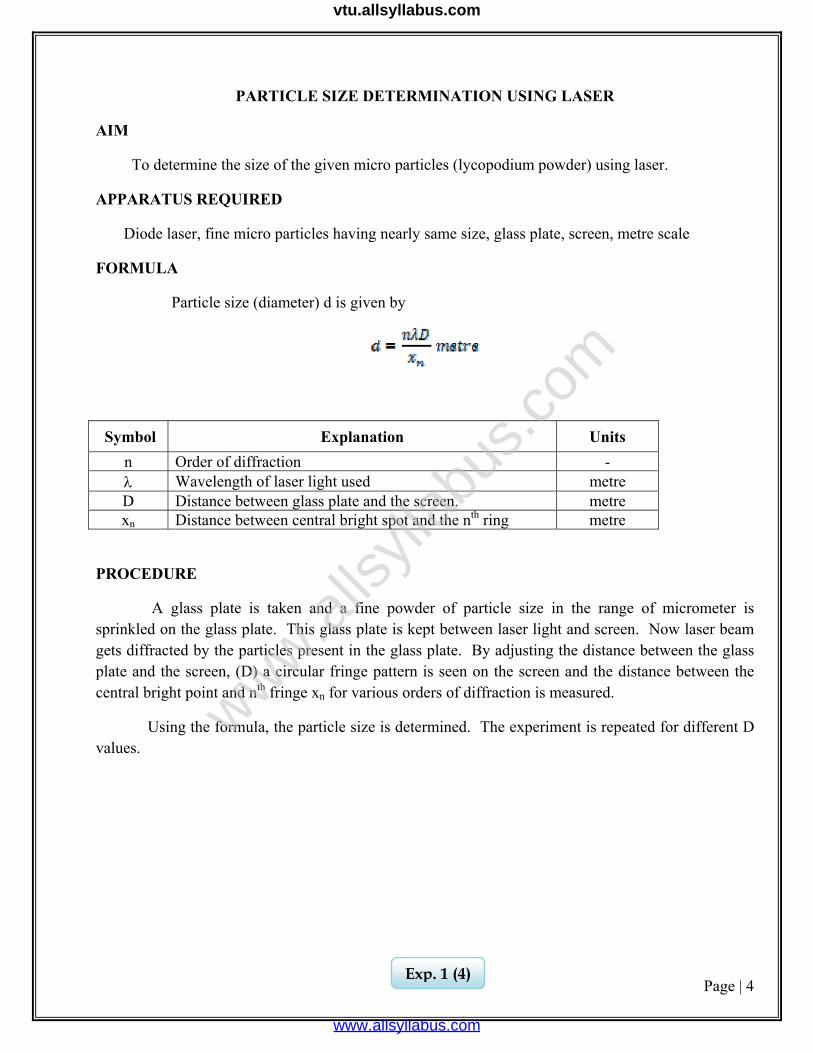
PARTICLE SIZE DETERMINATION USING LASER
AIM
To determine the size of the given micro particles (lycopodium powder) using laser.
APPARATUS REQUIRED
Diode laser, fine micro particles having nearly same size, glass plate, screen, metre scale
FORMULA
Particle size (diameter) d is given by
Symbol Explanation Units n Order of diffraction - λ Wavelength of laser light used metre D Distance between glass plate and the screen. metre xn Distance between central bright spot and the nth ring metre
PROCEDURE
A glass plate is taken and a fine powder of particle size in the range of micrometer is sprinkled on the glass plate. This glass plate is kept between laser light and screen. Now laser beam gets diffracted by the particles present in the glass plate. By adjusting the distance between the glass plate and the screen, (D) a circular fringe pattern is seen on the screen and the distance between the central bright point and nth fringe xn for various orders of diffraction is measured.
Using the formula, the particle size is determined. The experiment is repeated for different D values.
Exp. 1 (4)
www.alls
yllab
us.co
m
www.allsyllabus.com
vtu.allsyllabus.com
Page | 5
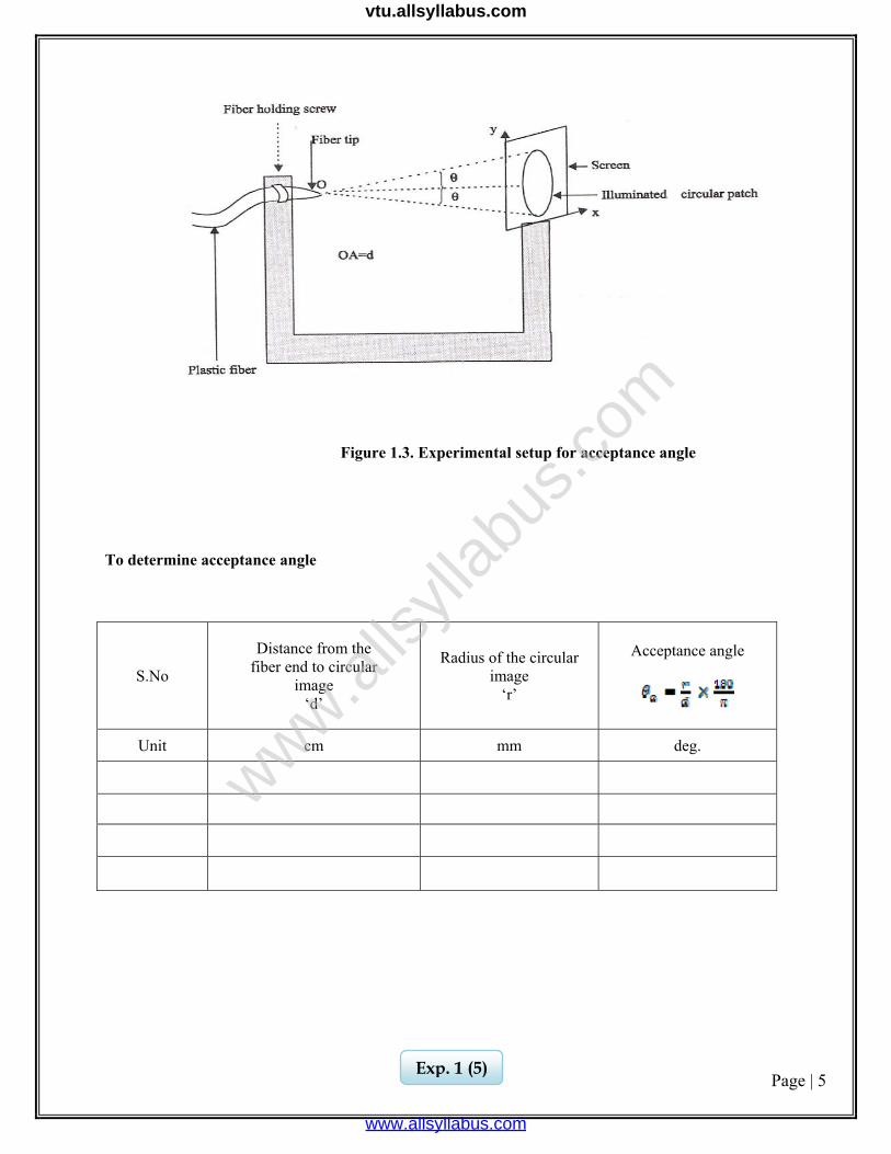
Figure 1.3. Experimental setup for acceptance angle
To determine acceptance angle
S.No
Distance from the fiber end to circular
image ‘d’
Radius of the circular image
‘r’
Acceptance angle
Unit cm mm deg.
Exp. 1 (5)
www.alls
yllab
us.co
m
www.allsyllabus.com
vtu.allsyllabus.com
Page | 6
1. (b) DETERMINATION OF ACCEPTANCE ANGLE IN AN OPTICAL FIBRE
AIM
To determine acceptance angle of an optical fiber.
APPARATUS REQUIRED
Laser for optical fiber light source, Laser power meter, optical fiber, optical fiber connectors and Numerical aperture Jig.
PRINCIPLE
The principle behind the transmission of light waves in an optical fiber is total internal reflection.
FORMULA
Acceptance angle deg
Symbol Explanation Unit
r Radius of the circular image metre d Distance from fibre end to circular image metre
PROCEDURE
Using laser, we can find the acceptance angle of the fiber optic cable. The given laser source is connected to the optical fiber cable. The other end is exposed to the air medium in the dark place. The emerging light is exposed on a plain paper.
Now, we get illuminated circular patch on the screen. The distance from the fiber end to circular image (d) is measured using meter scale. The radius of the circular image is also measured. Thus the acceptance angle is calculated
Exp. 1 (6)
www.alls
yllab
us.co
m
www.allsyllabus.com
vtu.allsyllabus.com
Page | 7
CALCULATION
(i) Wavelength of the laser source, metre
(ii) The size of the particle,
(iii) Acceptance angle,
deg
RESULTS i) Wavelength of the given source λ = ------------------- metre.
ii) The size of the particle d = ___________ m
iii) Acceptance angle θa = ___________ degree
Exp. 1 (7)
www.alls
yllab
us.co
m
www.allsyllabus.com
vtu.allsyllabus.com

Page | 8
www.alls
yllab
us.co
m
www.allsyllabus.com
vtu.allsyllabus.com
Page | 9
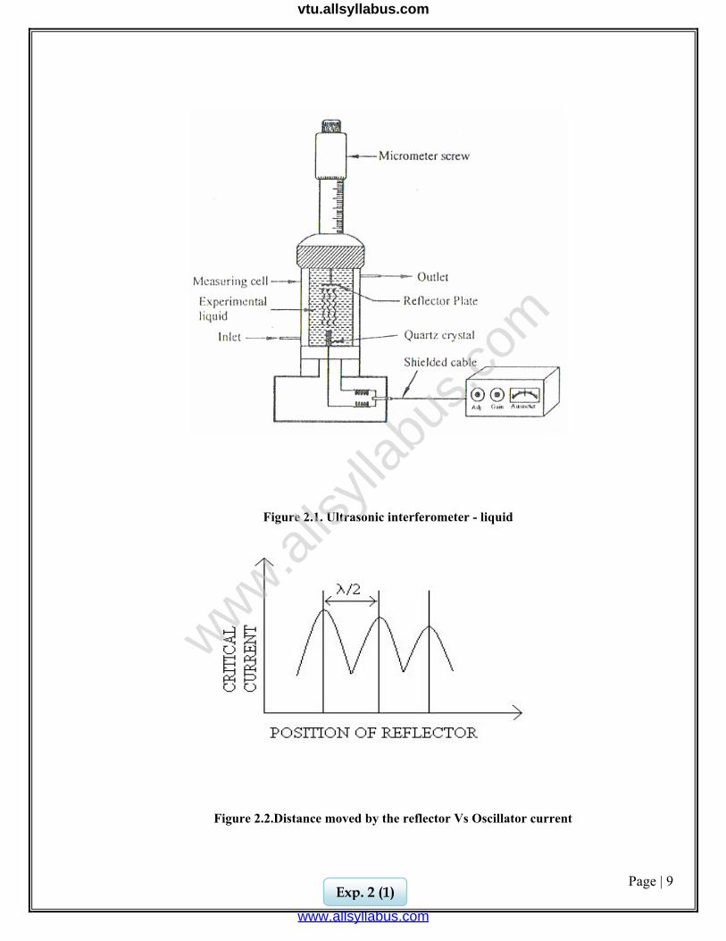
Figure 2.1. Ultrasonic interferometer - liquid
Figure 2.2.Distance moved by the reflector Vs Oscillator current
Exp. 2 (1)
www.alls
yllab
us.co
m
www.allsyllabus.com
vtu.allsyllabus.com
Page | 10
Ex.No: Date: 2. ULTRASONIC INTERFEROMETER AIM
1. To determine the velocity of ultrasonic wave in the medium of liquid
using ultrasonic interferometer. 2. To determine the compressibility of the given liquid.
APPARATUS REQUIRED
Ultrasonic interferometer (High frequency generator, measuring cell), given liquid.
PRINCIPLE
High frequency generator, which excites the quartz crystal, generates longitudinal ultrasonic wave in the experimental liquid. Standing waves are formed within the medium. This results in the formation of resonance and causes a change in the potential difference at the generator which excites the crystal. Due to this, anode current of the generator becomes maximum. The change in the anode current can be measured from the micrometer.
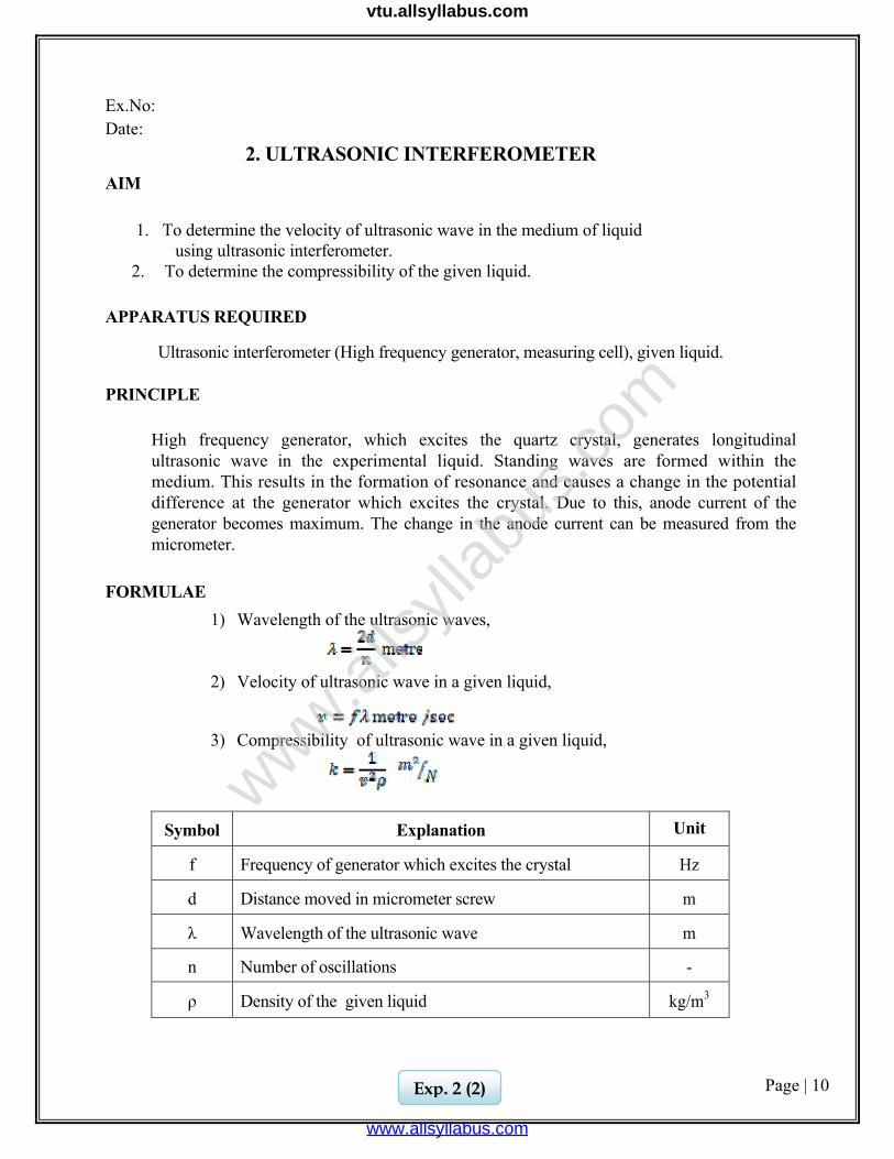
FORMULAE 1) Wavelength of the ultrasonic waves,
2) Velocity of ultrasonic wave in a given liquid,
3) Compressibility of ultrasonic wave in a given liquid,
Symbol Explanation Unit
f Frequency of generator which excites the crystal Hz
d Distance moved in micrometer screw m
λ Wavelength of the ultrasonic wave m
n Number of oscillations -
ρ Density of the given liquid kg/m3
Exp. 2 (2)
www.alls
yllab
us.co
m
www.allsyllabus.com
vtu.allsyllabus.com
Page | 11
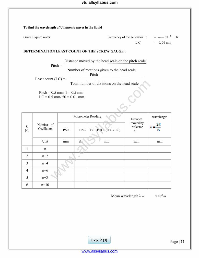
To find the wavelength of Ultrasonic waves in the liquid Given Liquid: water Frequency of the generator f = ----- x106 Hz L.C = 0. 01 mm DETERMINATION LEAST COUNT OF THE SCREW GAUGE :
Distance moved by the head scale on the pitch scale Pitch = Number of rotations given to the head scale Pitch Least count (LC) = Total number of divisions on the head scale Pitch = 0.5 mm/ 1 = 0.5 mm LC = 0.5 mm/ 50 = 0.01 mm.
Mean wavelength λ = x 10-3 m
S. No
Number of Oscillation
Micrometer Reading
Distance moved by reflector
d
wavelength
PSR
HSC
TR = PSR + (HSC x LC)
Unit mm div mm mm mm
1 n
2 n+2
3 n+4
4 n+6
5 n+8
6 n+10
Exp. 2 (3)
www.alls
yllab
us.co
m
www.allsyllabus.com
vtu.allsyllabus.com
Page | 12
PROCEDURE
The high frequency generator is switched on and the alternating field from the generator is applied to the quartz crystal. The quartz crystal produces longitudinal ultrasonic waves. The ultrasonic wave passes through the liquid and gets reflected at the surface of the reflector plate.
If the distance between the reflector and crystal is exactly a whole multiple of the sound wavelength, standing waves are formed within the medium. This results in the formation of acoustics resonance and cause a change in the potential difference at the generator which excites the crystal. Due to this, anode current of the generator becomes maximum. The change in the anode current can be measured from the micrometer fitted with the frequency generator.
The distance between the reflector and crystal is varied using the micrometer screw such that the anode current decreases from maximum and then increases up to a maximum. The distance of separation between successive maximum or minimum in the anode current is equal to half the wavelength of the ultrasonic waves in the liquid. By noting the initial and final position of the micrometer for two complete oscillations (maxima -minima-maxima), one can determine the distance moved by the parallel reflector. Thus ‘n’ number of successive maxima or minima is recorded for a distance d. The total distance moved by the micrometer screw is given by d = n λ/2 metre or Wavelength λ = 2d / n metre
From the value of λ, the velocity of the longitudinal ultrasonic waves is calculated using the relation, v = fλ, where f is the frequency of the generator which is used to excite the crystal. After determining the velocity of the ultrasonic waves in liquid is calculated using the formula k =1/v2ρ where ρ is the density of the liquid.
CALCULATION
Frequency of the generator f = …………. x 10 6 Hz Wavelength of the ultrasonic waves λ = …………. m Density of the given liquid ρ = …………. kg m-3
Number of oscillations n = ………….
Exp. 2 (4)
www.alls
yllab
us.co
m
www.allsyllabus.com
vtu.allsyllabus.com
Page | 13
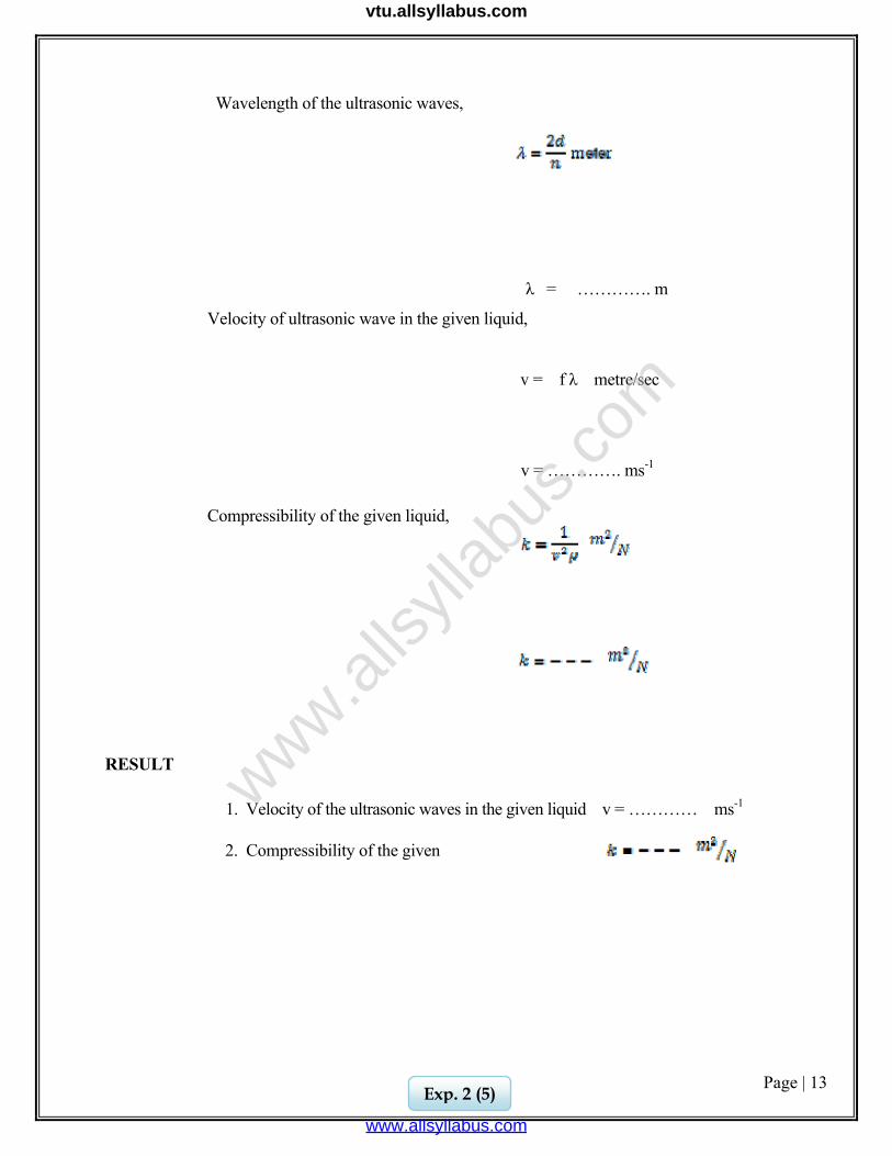
Wavelength of the ultrasonic waves,
λ = …………. m
Velocity of ultrasonic wave in the given liquid,
v = f λ metre/sec
v = …………. ms-1
Compressibility of the given liquid,
RESULT
1. Velocity of the ultrasonic waves in the given liquid v = ………… ms-1
2. Compressibility of the given
Exp. 2 (5)
www.alls
yllab
us.co
m
www.allsyllabus.com
vtu.allsyllabus.com

Page | 14
www.alls
yllab
us.co
m
www.allsyllabus.com
vtu.allsyllabus.com
Page | 15
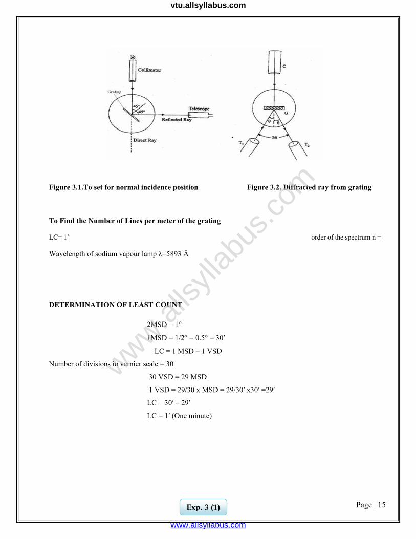
Figure 3.1.To set for normal incidence position Figure 3.2. Diffracted ray from grating
To Find the Number of Lines per meter of the grating
LC= 1’ order of the spectrum n =
Wavelength of sodium vapour lamp λ=5893 Å
DETERMINATION OF LEAST COUNT
2MSD = 1°
1MSD = 1/2° = 0.5° = 30′
LC = 1 MSD – 1 VSD
Number of divisions in vernier scale = 30
30 VSD = 29 MSD
1 VSD = 29/30 x MSD = 29/30′ x30′ =29′
LC = 30′ – 29′
LC = 1′ (One minute)
Exp. 3 (1)
www.alls
yllab
us.co
m
www.allsyllabus.com
vtu.allsyllabus.com
Page | 16
Ex. No. : Date :
3. SPECTROMETER - DETERMINATION OF WAVELENGTH OF MERCURY SPECTRUM
AIM
To determine the wavelength of the mercury (Hg) spectrum using the plane transmission grating.
APPARATUS REQUIRED
Spectrometer, Sodium vapour lamp, Plane transmission grating, spirit level, Mercury vapour lamp, and reading lens.
PRINCIPLE A plane sheet of transparent material on which a large number of equidistant opaque rulings are made with a diamond point forms grating. The space between the rulings and transparent area constitute a parallel slit. When light passes through such a grating, diffraction takes place. Angle of diffraction depends upon the wavelength of the light and number of lines per metre on the grating. So the number of lines per metre in grating and wavelength of the source can be calculated.
FORMULA
The wavelength of the spectral lines of mercury spectrum
Symbol Explanation Unit θ Angle of diffraction degN Number of lines/ metre lines/ metre n Order of spectrum no unit
Exp. 3 (2)
www.alls
yllab
us.co
m
www.allsyllabus.com
vtu.allsyllabus.com

Page | 17
To
dete
rmin
e th
e w
avel
engt
h(λ)
of t
he p
rom
inen
t lin
es o
f the
mer
cury
spec
trum
Leas
t cou
nt =
1’
O
rder
of t
he sp
ectru
m n
= 1
N
= …
……
……
……
……
……
….li
nes/
met
er
TR
= M
SR +
(V
SC x
LC
)
met
er
Mea
n an
gle
of
diff
ract
ion
θ deg.
Mea
n
2θ
deg.
Diff
eren
ce b
etw
een
Ver
nier
A
and
V
erni
er B
2θ
=B1∼
B2
deg.
2θ
=A1∼
A2
deg.
Rea
ding
s for
diff
ract
ed im
age
Rig
ht si
de V
erni
er B
(B
2)
TR
deg.
VSC
div.
MSR
deg.
Ver
nier
A
(A2)
TR
deg.
VSC
div.
MSR
deg.
Left
Sid
e
Ver
nier
B
(B1)
TR
deg.
VSC
div.
MSR
deg.
Ver
nier
A
(A1)
TR
deg.
VSC
div.
MSR
deg.
Sp
ectra
l lin
es
(col
ours
)
Vio
let
Blu
e
Gre
en
Yel
low
Red
www.alls
yllab
us.co
m
www.allsyllabus.com
vtu.allsyllabus.com
Page | 18
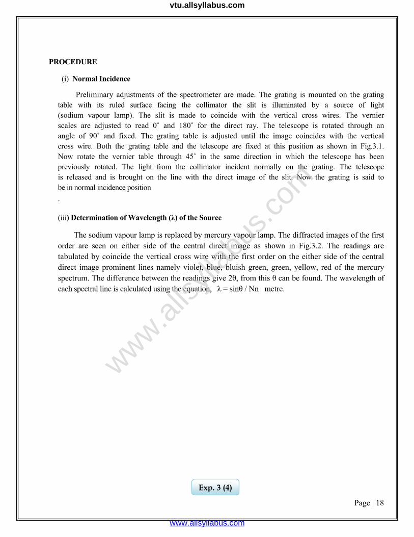
PROCEDURE
(i) Normal Incidence
Preliminary adjustments of the spectrometer are made. The grating is mounted on the grating table with its ruled surface facing the collimator the slit is illuminated by a source of light (sodium vapour lamp). The slit is made to coincide with the vertical cross wires. The vernier scales are adjusted to read 0˚ and 180˚ for the direct ray. The telescope is rotated through an angle of 90˚ and fixed. The grating table is adjusted until the image coincides with the vertical cross wire. Both the grating table and the telescope are fixed at this position as shown in Fig.3.1. Now rotate the vernier table through 45˚ in the same direction in which the telescope has been previously rotated. The light from the collimator incident normally on the grating. The telescope is released and is brought on the line with the direct image of the slit. Now the grating is said to be in normal incidence position .
(iii) Determination of Wavelength (λ) of the Source
The sodium vapour lamp is replaced by mercury vapour lamp. The diffracted images of the first order are seen on either side of the central direct image as shown in Fig.3.2. The readings are tabulated by coincide the vertical cross wire with the first order on the either side of the central direct image prominent lines namely violet, blue, bluish green, green, yellow, red of the mercury spectrum. The difference between the readings give 2θ, from this θ can be found. The wavelength of each spectral line is calculated using the equation, λ = sinθ / Nn metre.
Exp. 3 (4)
www.alls
yllab
us.co
m
www.allsyllabus.com
vtu.allsyllabus.com
Page | 19
CALCULATION
Order of the spectrum n = 1
1. The wavelength of the spectral lines of mercury spectrum,
Wavelength for violet,
λv =……………….Å
Wavelength for blue λB =……………….Å
Wavelength for green λG=……………… Å
Exp. 3 (5)
www.alls
yllab
us.co
m
www.allsyllabus.com
vtu.allsyllabus.com
Page | 20
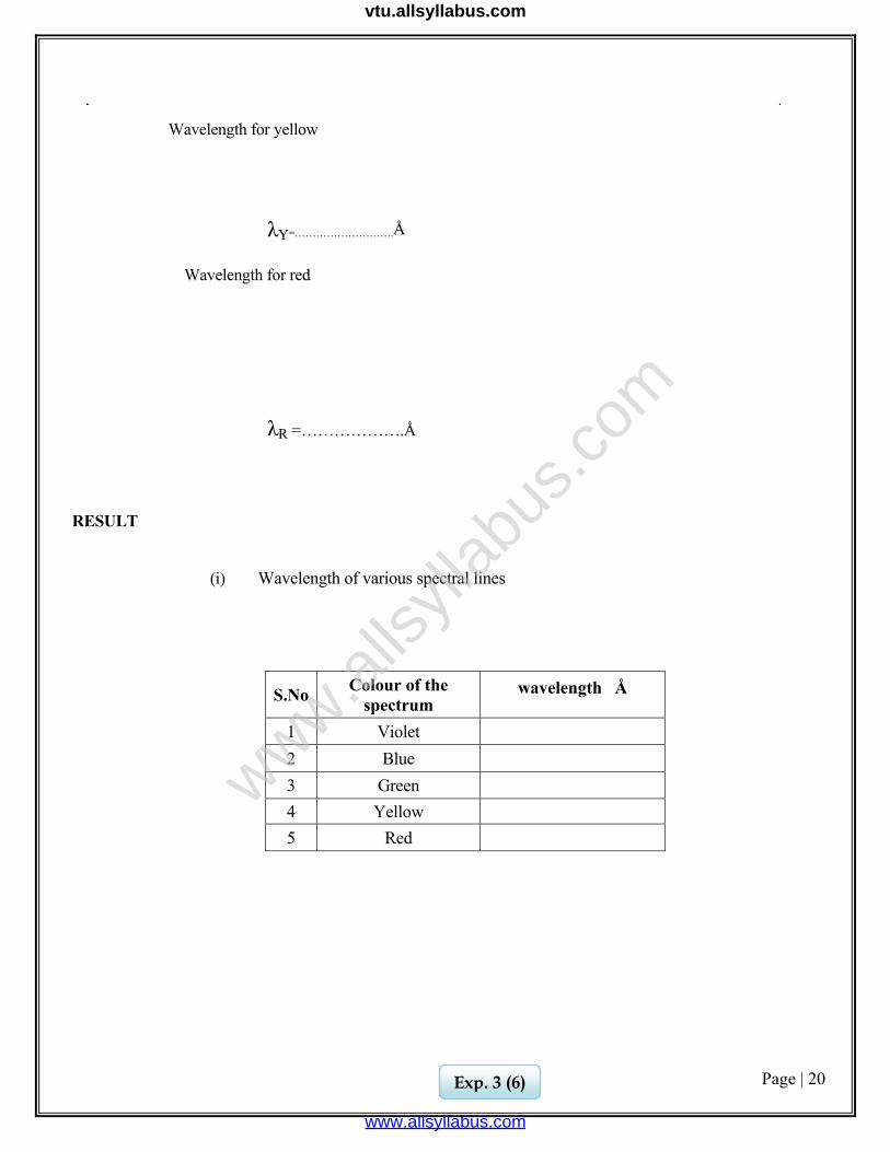
Wavelength for yellow λY=……………………….Å Wavelength for red λR =……………….Å
RESULT
(i) Wavelength of various spectral lines
S.No Colour of the spectrum
wavelength Å
1 Violet
2 Blue
3 Green
4 Yellow 5 Red
Exp. 3 (6)
www.alls
yllab
us.co
m
www.allsyllabus.com
vtu.allsyllabus.com
Page | 21
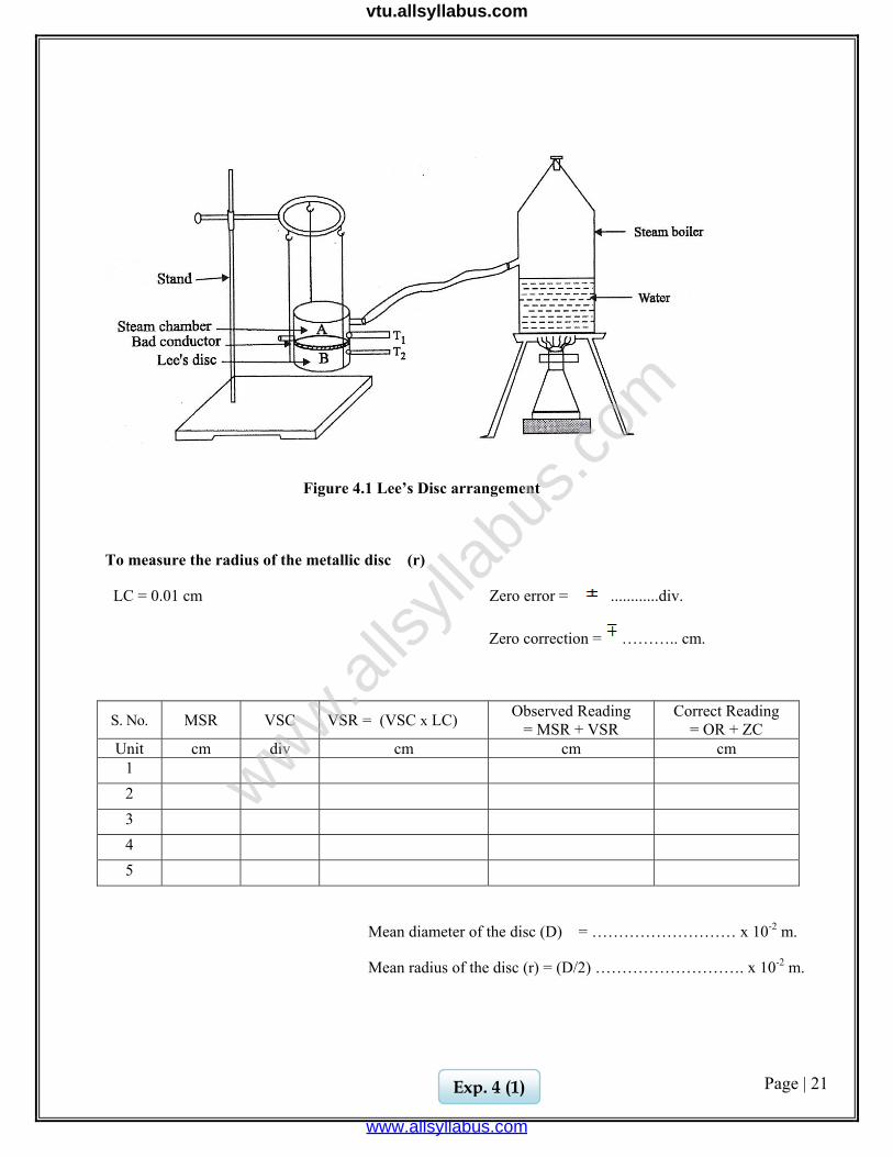
Figure 4.1 Lee’s Disc arrangement
To measure the radius of the metallic disc (r)
LC = 0.01 cm Zero error = ............div.
Zero correction = ……….. cm.
S. No. MSR VSC VSR = (VSC x LC) Observed Reading = MSR + VSR
Correct Reading = OR + ZC
Unit cm div cm cm cm 1 2 3 4 5
Mean diameter of the disc (D) = ……………………… x 10-2 m.
Mean radius of the disc (r) = (D/2) ………………………. x 10-2 m.
Exp. 4 (1)
www.alls
yllab
us.co
m
www.allsyllabus.com
vtu.allsyllabus.com
Page | 22
Ex.No. : Date :
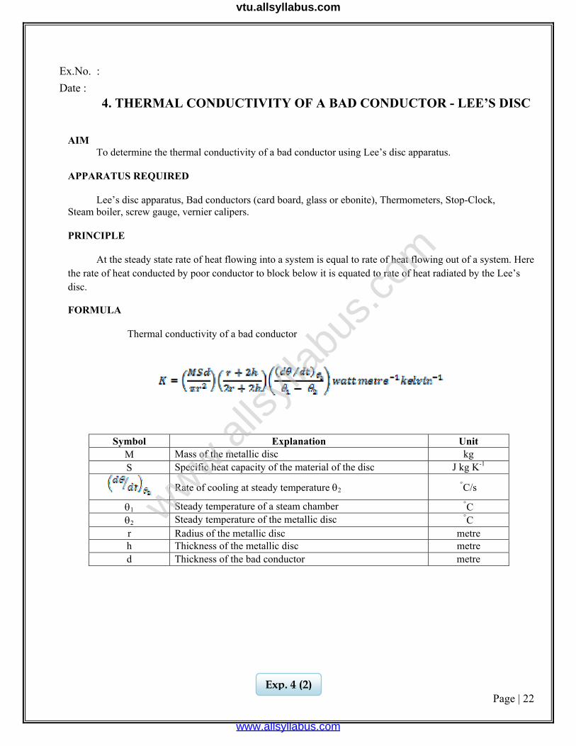
4. THERMAL CONDUCTIVITY OF A BAD CONDUCTOR - LEE’S DISC AIM To determine the thermal conductivity of a bad conductor using Lee’s disc apparatus. APPARATUS REQUIRED Lee’s disc apparatus, Bad conductors (card board, glass or ebonite), Thermometers, Stop-Clock, Steam boiler, screw gauge, vernier calipers. PRINCIPLE At the steady state rate of heat flowing into a system is equal to rate of heat flowing out of a system. Here the rate of heat conducted by poor conductor to block below it is equated to rate of heat radiated by the Lee’s disc.
FORMULA Thermal conductivity of a bad conductor
Symbol Explanation Unit M Mass of the metallic disc kg S Specific heat capacity of the material of the disc J kg K-1
Rate of cooling at steady temperature θ2 °C/s
θ1 Steady temperature of a steam chamber °C θ2 Steady temperature of the metallic disc °C r Radius of the metallic disc metre h Thickness of the metallic disc metre d Thickness of the bad conductor metre
Exp. 4 (2)
www.alls
yllab
us.co
m
www.allsyllabus.com
vtu.allsyllabus.com
Page | 23
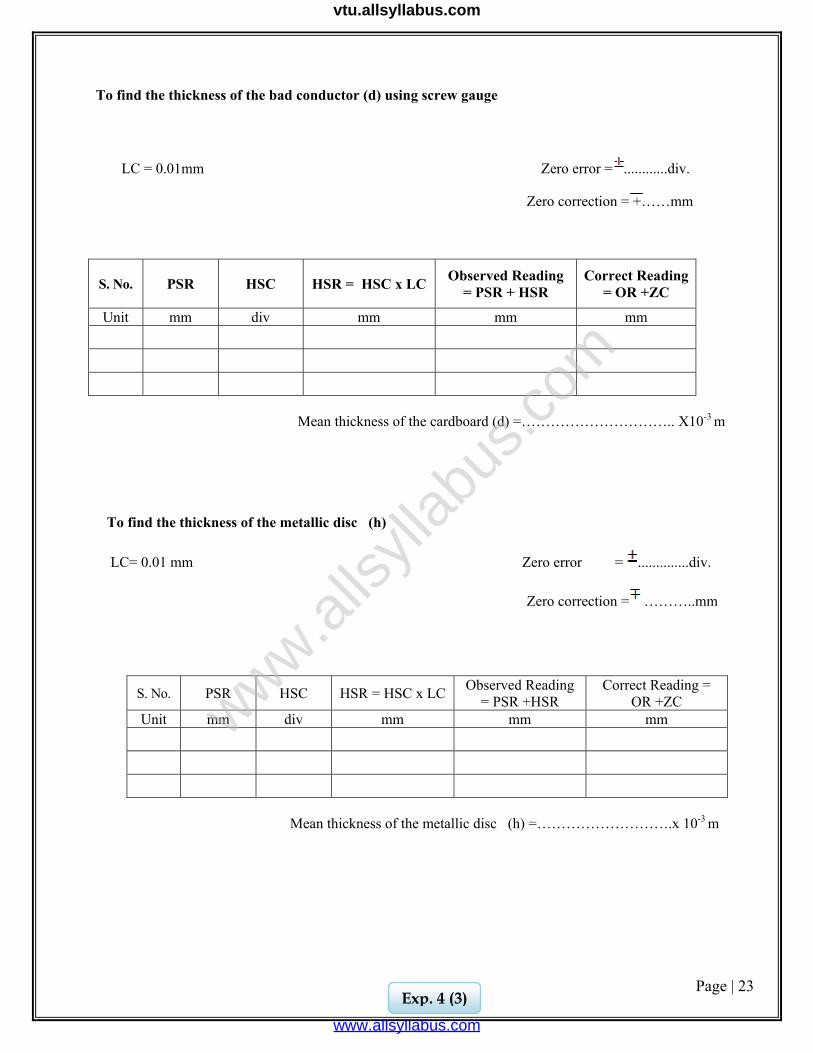
To find the thickness of the bad conductor (d) using screw gauge LC = 0.01mm Zero error = ............div.
Zero correction = +……mm
S. No. PSR HSC HSR = HSC x LC Observed Reading = PSR + HSR
Correct Reading = OR +ZC
Unit mm div mm mm mm Mean thickness of the cardboard (d) =………………………….. X10-3 m To find the thickness of the metallic disc (h) LC= 0.01 mm Zero error = ..............div.
Zero correction = ………..mm
S. No. PSR HSC HSR = HSC x LC Observed Reading = PSR +HSR
Correct Reading = OR +ZC
Unit mm div mm mm mm
Mean thickness of the metallic disc (h) =……………………….x 10-3 m
Exp. 4 (3)
www.alls
yllab
us.co
m
www.allsyllabus.com
vtu.allsyllabus.com
Page | 24
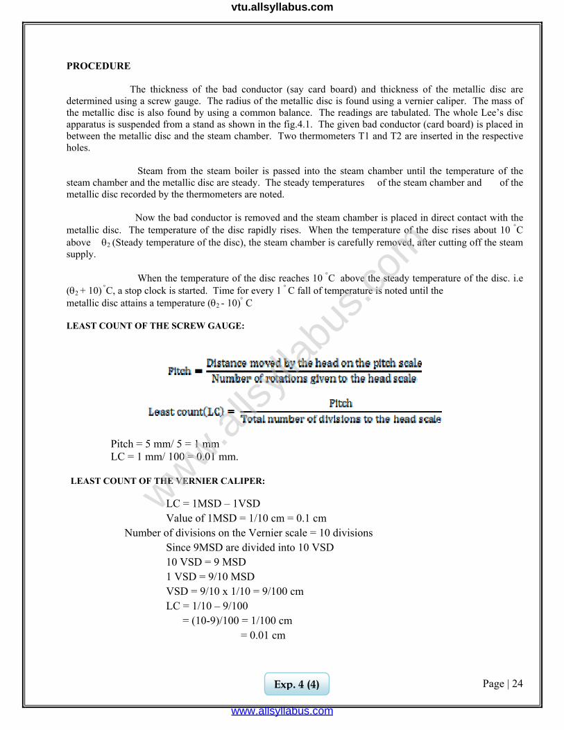
PROCEDURE The thickness of the bad conductor (say card board) and thickness of the metallic disc are determined using a screw gauge. The radius of the metallic disc is found using a vernier caliper. The mass of the metallic disc is also found by using a common balance. The readings are tabulated. The whole Lee’s disc apparatus is suspended from a stand as shown in the fig.4.1. The given bad conductor (card board) is placed in between the metallic disc and the steam chamber. Two thermometers T1 and T2 are inserted in the respective holes. Steam from the steam boiler is passed into the steam chamber until the temperature of the steam chamber and the metallic disc are steady. The steady temperatures of the steam chamber and of the metallic disc recorded by the thermometers are noted.
Now the bad conductor is removed and the steam chamber is placed in direct contact with the metallic disc. The temperature of the disc rapidly rises. When the temperature of the disc rises about 10 °C above θ2 (Steady temperature of the disc), the steam chamber is carefully removed, after cutting off the steam supply. When the temperature of the disc reaches 10 °C above the steady temperature of the disc. i.e (θ2 + 10) °C, a stop clock is started. Time for every 1 ° C fall of temperature is noted until the metallic disc attains a temperature (θ2 - 10)° C LEAST COUNT OF THE SCREW GAUGE:
Pitch = 5 mm/ 5 = 1 mm LC = 1 mm/ 100 = 0.01 mm.
LEAST COUNT OF THE VERNIER CALIPER:
LC = 1MSD – 1VSD Value of 1MSD = 1/10 cm = 0.1 cm
Number of divisions on the Vernier scale = 10 divisions Since 9MSD are divided into 10 VSD 10 VSD = 9 MSD 1 VSD = 9/10 MSD VSD = 9/10 x 1/10 = 9/100 cm LC = 1/10 – 9/100
= (10-9)/100 = 1/100 cm = 0.01 cm
Exp. 4 (4)
www.alls
yllab
us.co
m
www.allsyllabus.com
vtu.allsyllabus.com
Page | 25
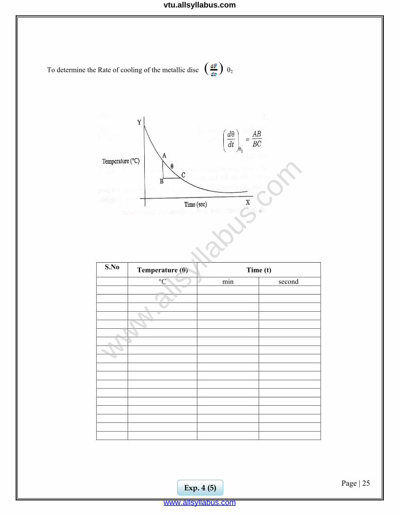
To determine the Rate of cooling of the metallic disc ( ) θ2
S.No Temperature (θ) Time (t) °C min second
Exp. 4 (5)
www.alls
yllab
us.co
m
www.allsyllabus.com
vtu.allsyllabus.com
Page | 26
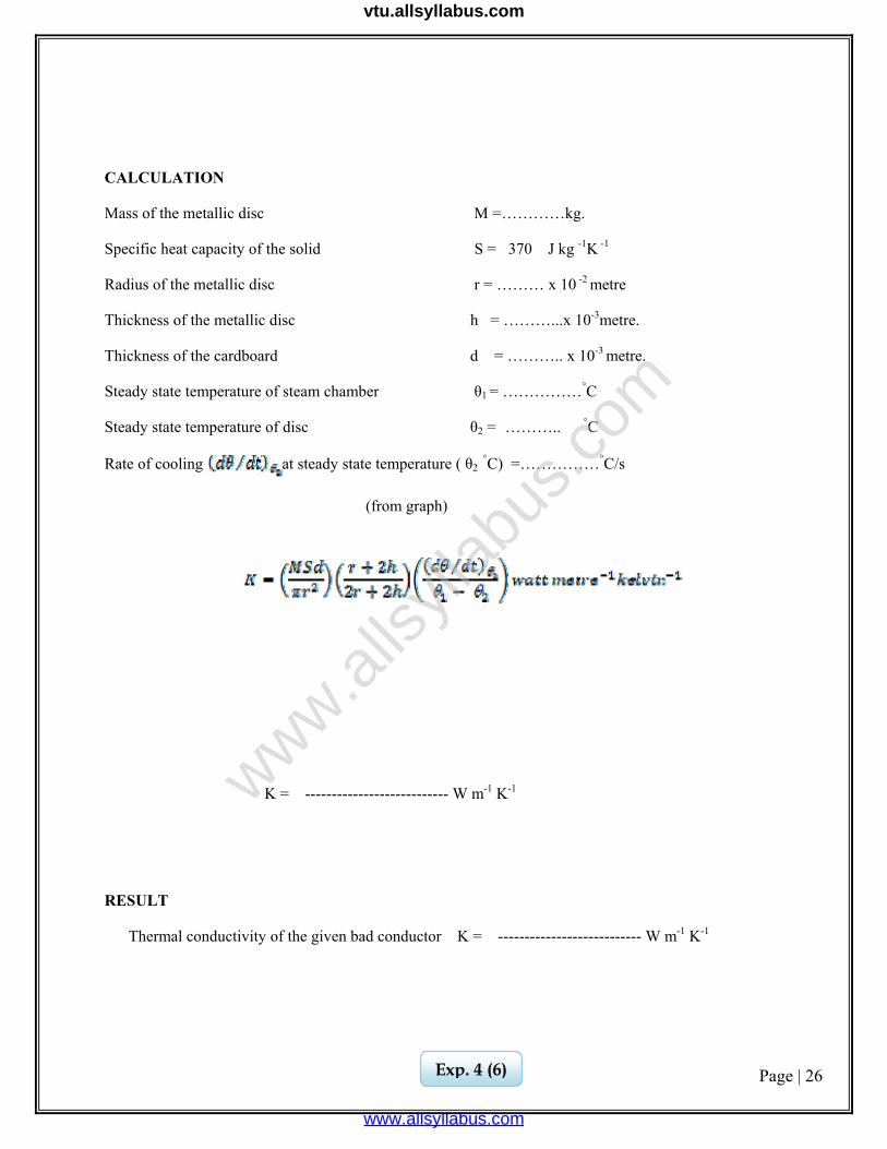
CALCULATION
Mass of the metallic disc M =…………kg.
Specific heat capacity of the solid S = 370 J kg -1K -1
Radius of the metallic disc r = ……… x 10 -2 metre
Thickness of the metallic disc h = ………...x 10-3metre.
Thickness of the cardboard d = ……….. x 10-3 metre.
Steady state temperature of steam chamber θ1 = ……………°C
Steady state temperature of disc θ2 = ……….. °C
Rate of cooling at steady state temperature ( θ2 °C) =……………°C/s
(from graph)
K = --------------------------- W m-1 K-1
RESULT
Thermal conductivity of the given bad conductor K = --------------------------- W m-1 K-1
Exp. 4 (6)
www.alls
yllab
us.co
m
www.allsyllabus.com
vtu.allsyllabus.com
Page | 27
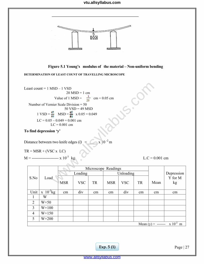
Figure 5.1 Young’s modulus of the material – Non-uniform bending
DETERMINATION OF LEAST COUNT OF TRAVELLING MICROSCOPE
Least count = 1 MSD – 1 VSD 20 MSD = 1 cm Value of 1 MSD = cm = 0.05 cm
Number of Vernier Scale Division = 50 50 VSD = 49 MSD 1 VSD = MSD = x 0.05 = 0.049
LC = 0.05 – 0.049 = 0.001 cm LC = 0.001 cm
To find depression ‘y’
Distance between two knife edges (l) = _____ x 10 -2 m
TR = MSR + (VSC x LC)
M = -------------------- x 10-3 kg L.C = 0.001 cm
S.No Load
Microscope Readings
Mean
DepressionY for M
kg
Loading Unloading MSR
VSC
TR
MSR
VSC
TR
Unit x 10-3kg cm div cm cm div cm cm cm 1 W 2 W+50 3 W+100 4 W+150 5 W+200
Mean (y) = ------- x 10-2 m
Exp. 5 (1)
www.alls
yllab
us.co
m
www.allsyllabus.com
vtu.allsyllabus.com
Page | 28
Ex.No. : Date:
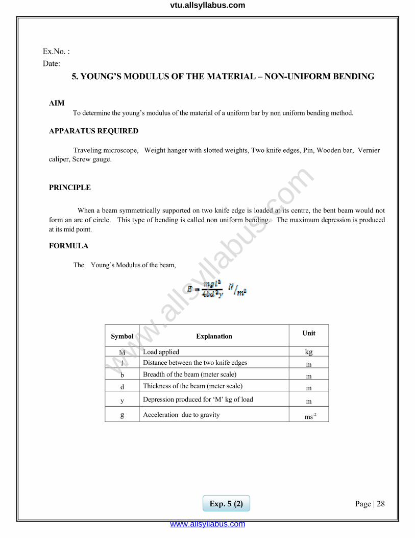
5. YOUNG’S MODULUS OF THE MATERIAL – NON-UNIFORM BENDING
AIM To determine the young’s modulus of the material of a uniform bar by non uniform bending method.
APPARATUS REQUIRED
Traveling microscope, Weight hanger with slotted weights, Two knife edges, Pin, Wooden bar, Vernier
caliper, Screw gauge.
PRINCIPLE
When a beam symmetrically supported on two knife edge is loaded at its centre, the bent beam would not form an arc of circle. This type of bending is called non uniform bending. The maximum depression is produced at its mid point.
FORMULA
The Young’s Modulus of the beam,
Symbol Explanation Unit
M Load applied kg l Distance between the two knife edges m b Breadth of the beam (meter scale) m d Thickness of the beam (meter scale) m
y Depression produced for ‘M’ kg of load m
g Acceleration due to gravity ms-2
Exp. 5 (2)
www.alls
yllab
us.co
m
www.allsyllabus.com
vtu.allsyllabus.com
Page | 29
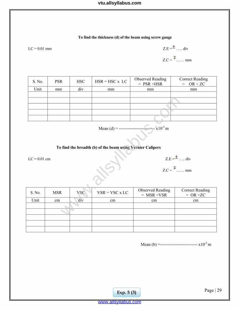
To find the thickness (d) of the beam using screw gauge
LC = 0.01 mm Z.E = ….. div
Z.C = …… mm
S. No. PSR HSC HSR = HSC x LC Observed Reading = PSR +HSR
Correct Reading = OR + ZC
Unit mm div mm mm mm
Mean (d) = ------------------------- x10-3 m
To find the breadth (b) of the beam using Vernier Calipers
LC = 0.01 cm Z.E = ….. div
Z.C = …… mm
S. No. MSR VSC VSR = VSC x LC Observed Reading = MSR +VSR
Correct Reading = OR +ZC
Unit cm div cm cm cm
Mean (b) =-------------------------- x10-2 m
Exp. 5 (3)
www.alls
yllab
us.co
m
www.allsyllabus.com
vtu.allsyllabus.com
Page | 30
PROCEDURE
The weight of the hanger is taken as the dead load ‘w’. The wooden bar is brought to elastic mood by loading and unloading it, a number of times with slotted weights. With the dead load w suspended from the midpoint, the microscope is adjusted such that the horizontal cross-wire coincides with the image of the tip of the pin. The reading in the vertical scale is taken. The experiment is repeated by adding weights in steps of 50 gm each. Every time the microscope is adjusted and the vertical scale reading is taken. Then the load is decreased in the same steps and the readings are taken. From the readings, the mean depression of the mid-point for a given load can be found. The length of the wooden bar between the knife edges is measured (l).
The wooden bar is removed and its mean breadth ‘b’ and mean thickness ‘d’are determined with a vernier caliper and a screw gauge respectively. From the observations, Young modulus of the material of the beam is calculated by using the given formula.
Exp. 5 (4)
www.alls
yllab
us.co
m
www.allsyllabus.com
vtu.allsyllabus.com
Page | 31
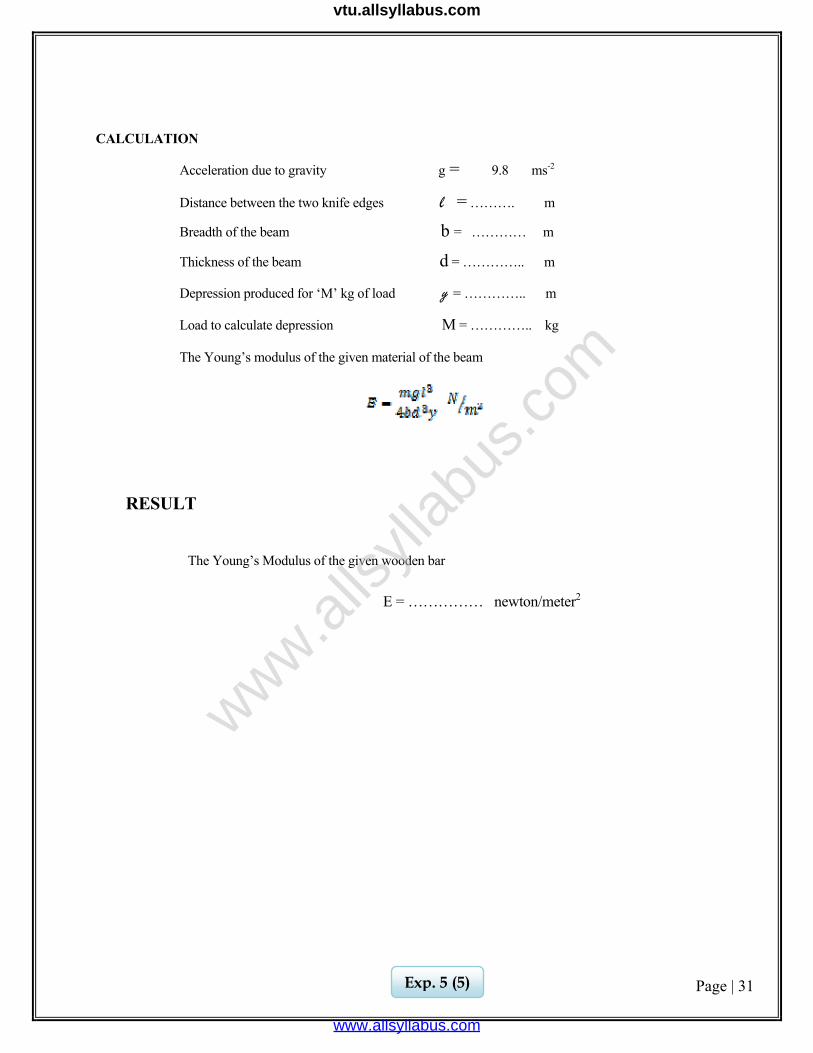
CALCULATION
Acceleration due to gravity g = 9.8 ms-2
Distance between the two knife edges l = ………. m
Breadth of the beam b = ………… m
Thickness of the beam d = ………….. m
Depression produced for ‘M’ kg of load y = ………….. m
Load to calculate depression M = ………….. kg
The Young’s modulus of the given material of the beam
RESULT
The Young’s Modulus of the given wooden bar
E = …………… newton/meter2
Exp. 5 (5)
www.alls
yllab
us.co
m
www.allsyllabus.com
vtu.allsyllabus.com
Page | 32
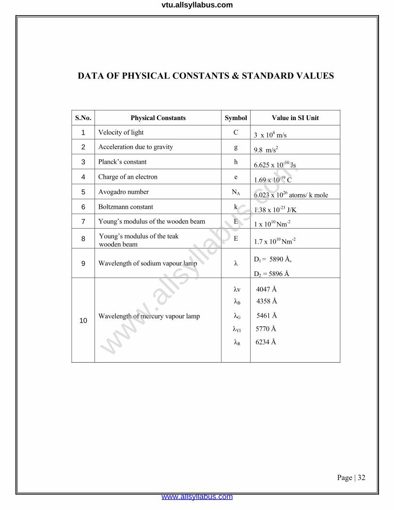
DATA OF PHYSICAL CONSTANTS & STANDARD VALUES
S.No. Physical Constants Symbol Value in SI Unit
1 Velocity of light C 3 x 10⁸ m/s
2 Acceleration due to gravity g 9.8 m/s2
3 Planck’s constant h 6.625 x 10⁻³⁴ Js
4 Charge of an electron e 1.69 x 10⁻¹⁹ C
5 Avogadro number NA 6.023 x 1026 atoms/ k mole
6 Boltzmann constant k 1.38 x 10⁻²³ J/K
7 Young’s modulus of the wooden beam E 1 x 10¹⁰ Nm-2
8 Young’s modulus of the teak wooden beam
E 1.7 x 10¹⁰ Nm-2
9 Wavelength of sodium vapour lamp λ D1 = 5890 Å,
D2 = 5896 Å
10 Wavelength of mercury vapour lamp
λv
λB
λG
λYI
λR
4047 Å
4358 Å
5461 Å
5770 Å
6234 Å www.alls
yllab
us.co
m
www.allsyllabus.com
vtu.allsyllabus.com
Page | 33
VIVA QUESTIONS & ANSWERS
1. LASER PARAMETERS 1. Define LASER?
The term LASER stands for Light Amplification by Stimulated Emission of Radiation. It is a device which produces a powerful, monochromatic collimated beam of light in which the waves are coherent.
2. What is meant by active material in laser?
The material in which the population inversion is achieved is called active material. 3. What is semi conductor diode laser?
Semiconductor diode laser is a specially fabricated pn junction diode. It emits laser light when it is forward biased.
4. What are the characteristic of laser radiation?
Laser radiations have high intensity, high coherence, monochromatic and high
directionality with less divergence.
5. What is stimulated emission?
The process of forced emission of photons caused by incident photons is called stimulated emission
6. Define acceptance angle
The maximum with which a ray of light can enter through one end of the fiber and still be totally internally reflected is called acceptance angle of the fiber. 7. What is the principle used in fiber optic communication system?
The principle behind the transmission of light waves in an optical fiber is total internal reflection
www.alls
yllab
us.co
m
www.allsyllabus.com
vtu.allsyllabus.com
Page | 34
2. ULTRASONIC INTERFEROMETER
1. What are ultrasonics? The sound waves having frequencies above the audible range. i.e, frequencies above
20,000Hz to20KHz are known as ultrasonics.
2. What is piezo – electric effect? When mechanical pressure is applied to one pair of opposite faces of a quartz crystal,
then the other pair of opposite faces develop equal and opposite electrical charges on the crystal.
3. What is inverse piezo electric effect?
The piezo electric effect is reversible. If an electric field is applied to one pair of opposite faces of quartz crystal, alternative mechanical expansion or contraction (pressure) is produced across the other pair of opposite faces of the crystal.
4. What is an acoustic grating?
When ultrasonic waves travel through a transparent liquid, due to alternating compression and rarefraction, longitudinal waves are formed. If a monochromatic light is passed through the liquid perpendicular to the waves, the liquid behaves a diffraction grating such a grating is known as “acoustic grating”
3.SPECTROMETER GRATING
1. What is plane transmission diffraction grating?
A plane transmission diffraction grating is an optically plane parallel glass plate on which equidistant, extremely close grooves are made by ruling with a diamond point. 2. In our experiment. What class of diffraction does occur and how?
Fraunhofer class of diffraction occurs. Since the spectrometer is focused for parallel rays, the source and the image are effectively at infinite distances from the grating. 3. How are the commercial gratings are made?
A commercial grating is made by pouring properly diluted cellulose acetate on the actual grating and drying it to a thin strong film. The film is detached from the original grating and is mounted between two glass plates. A commercial grating is called replica grating. In our experiment we use plane type replica grating.
www.alls
yllab
us.co
m
www.allsyllabus.com
vtu.allsyllabus.com
Page | 35
4. LEE’S DISC 1. What is thermal conductivity?
It is defined as the quantity of heat conducted per second normally across unit area of cross section of the material per unit temperature difference. It denotes the heat conducting power. Its unit is Watt meter‐1 kelvin‐1 2. Does the value of thermal conductivity depend on the dimension of the specimen?
No, it depends only on the material of the specimen.
3. Can this method be used for good conductors?
No, in that case, due to large conduction of heat, the temperature recorded by θ1 and θ2 will be very nearly the same 4. Is there any reason to take the specimen in the form of a disc?
A thin disc is taken because its area of cross section is large, while thickness is small. It increases the quantity of heat conducted across its faces.
5. YOUNGS MODULUS NONUNIFORM BENDING
1. What is young’s modulus?
Young’s modulus is defined as the ratio of longitudinal stress to longitudinal strain. 2. What is a beam?
When the lengths of the rod of uniform cross section is very large compared to its breadth such that the shearing stress over any section of the rod can be neglected, the rod is called beam. 3. How are longitudinal strain and stress produced in your experiment?
Due to depression, the upper or the concave side of the beam becomes smaller than the lower or the convex side of the beam. As a result, longitudinal strain is produced. The change in wave length of the beam. These forces will give rise to longitudinal stress. 4. Which dimension breath, thickness or length of the barshould be measured very careful and why?
The thickness of the bar should be measured very carefully since its magnitude is small and it occurs in the expression ‘E’ in the power of three. An inaccuracy in the measurement of the thickness will produce the greatest proportional error in ‘E’. 5. Why do you place the beam symmetrically on the knife edges?
To keep the reaction at the knife edges equal in conformity with the theory.
www.alls
yllab
us.co
m
www.allsyllabus.com
vtu.allsyllabus.com