Embed Size (px)
Citation preview

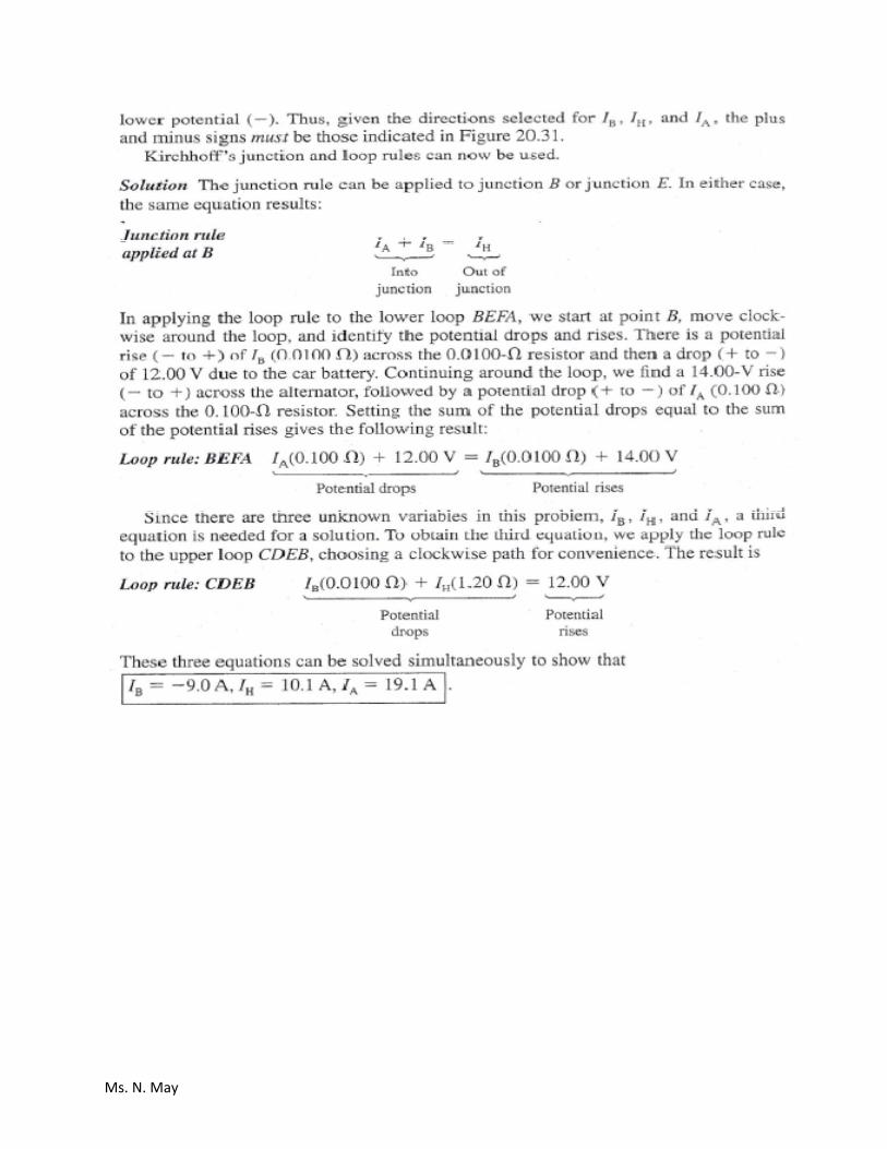
Ms. N. May
Physics Week 4(Sem. 2) Name____________________________
Chapter Summary
Electricity Power and Series/Parallel Circuits
Electric Power
Electrical power represents the rate at which energy is delivered to a resistor.
∆
This equation was developed by considering a battery delivering energy to a resistor, it also stands true for the power delivered by a voltage source to any device. Using Ohm’s law the power equation can then be
∆
This equation only applies to devices that follow ohm’s law. No matter whether you use high voltage and low current or low voltage and high current you still pay for it from the energy company. Energy (power) companies charge by the kilowatt‐hour. One kilowatt‐hour is the amount of power delivered in 1 hour at a constant rate of 1 kW. 1 kWh= 3.6 x 10⁶ J.
Resistors in Series
When two or more resistors are connected end to end, they are considered to be in series. The resistors can be light bulbs, heating elements, etc. The current in a series circuit is the same in the two resistors, because any charge that flows through resistor 1 (R1) must also flow through resistor 2 (R2). The sum of the potential difference across each resistor is equal to the total potential difference. So
∆
Therefore using the total potential difference in a series circuit with the current one can get an equivalent resistance. The equivalent resistance of a
series circuit for a circuit with two or more resistors is
The above equation demonstrating that the equivalent resistance for a series circuit is the algebraic sum of all of the resistors in the circuit.
Resistors in Parallel
For parallel circuits there are branch points where the electricity can follow different pathways. This creates separate circuits that have the same potential difference supplying all of them. Therefore each branch has the same potential difference and thus end up getting different currents depending on the resistance of the branch. Consider branch 1(or junction 1) having a resistance of R1 and a current of I1 and branch 2 having a resistance of R2 and current of I2. Since the electricity has the same change in potential (or potential difference) the larger part of the current will take the path of least resistance. Therefore the current in branch one (I1) will add with the current of branch 2 (I2) to become the total current of the main branch before the junction (or branch point). Using ohm’s law it reasons that
∆ &
∆
Thus the total current (before the branch point) represented by I would be
∆
Where Req is the equivalent resistance of a parallel circuit. Therefore the Req of a parallel circuit with two or more resistors is
1 1 1 1

Ms. N. May
Applications of Series and Parallel
Household circuits are wired in combination circuits, they are wired in parallel with some components wired in series to each other. So for example, all of the lights in a kitchen could be wired in series to each other. But the oven in the kitchen is wired in parallel to all of the lights. This allows for the oven to work despite one of the bulbs blowing. So the potential difference supplied to each branch (oven and lights) would be the same. However, the current to the light branch would probably be greater because the total resistance of the bulbs would be less than the resistance of the oven.
Circuit breakers
Also, important to note in household circuits are the use of circuit breakers. Circuit breakers are devices that monitor the current flow to a circuit and opens the circuit to stop electricity flow if the current exceeds a certain amount (15A or 20 A). The circuit breaker has a metal component that increases in size flipping the breaker (switch) when it gets too hot.
In older days fuses were used to stop electricity flow to a circuit drawing too much current. The way fuses work is if the current got too high a thin metal wire in the middle of the fuse would melt resulting in an open circuit. The problem was once a fuse blew it could not be reused.
Kirchhoff’s Rules
Circuits can be analyzed using Ohm’s law and the rules of series and parallel circuits however, some circuits are more difficult and can not be reduced to
having a single equivalent resistor. Therefore, Kirchhoff’s rules can be applied to simplify the analysis of such circuits
1. The sum of the currents entering any junction must equal the sum of the currents leaving that junction (junction rule).
2. The sum of the potential differences across all the elements around any closed circuit must be zero (loop rule).
The first rule is merely employing conservation of charge. It is analogous to water flowing in a pipe, the water flowing into a junction has to equal the sum of the water leaving the junction (assuming no leak).
The second rule is equivalent to the conservation of energy, any charge moving around a circuit (starting and ending at the same points) must gain as much energy as it loses.
Two decisions must be made before applying Kirchhoff’s rules, the direction of the current and a direction for traversing (crossing) the resistors.
Kirchhoff’s rules can only be used a limited number of times for each circuit. The first rule (junction rule) can only use as many times as you have individual branches. So in general it can be used one less time than the number of junction points in the circuit. The second rule (loop rule) can be used as long as it involves a new resistor. Three resistors lead to the application of the second rule three times. These equations can be combined to solve for the unknowns in the circuit.

Ms. N. May
EXAMPLE 5 • The Power and Energy Used in a Flashlight
In the flashlight in Figure 20,8, the current is 0.40 A, and the voltage is 3.0 V. Find (a) the power delivered to the bulb and (b) the energy dissipated in the bulb in 5.5 minutes of operation. Reasoning The electrical power delivered to the bulb is the product of the current and voltage. Since power is energy per unit time, the energy delivered to the bulb is the product of the power and time. Solution (a) The power is
P = IV = (0.40 A)(3.0 V) = 11.2W The "wattage" rating of this bulb would, therefore, be 1.2W. (b) The energy consumed in 5.5 minutes (330 s) follows from the definition of power as energy per unit time: Energy = PM = (1.2 W)(330 s) = 14.0 X 10² J EXAMPLE 8 • Resistors in a Series Circuit A 6.00-D resistor and a 3.00-D resistor are connected in series with a 12.0-V battery, as Figure 20.17 indicates. Assuming that the battery contributes no resistance to the circuit, find (a) the current, (b) the power dissipated in each resistor, and (c) the total power delivered to the resistors by the battery. Reasoning The current f can be determined from Ohm's law as f = VIRs, where
Rs = RI + R2 is the equivalent resistance of the two resistors. The power delivered to each resistor is given by Equation 20.6b as P = f2R, where R is the resistance of the resistor being considered and f is the current through it. The total power delivered by the battery is the power delivered to the 6.00-D resistor plus the power delivered to the 3.00-D resistor.

Ms. N. May
Solution (a) The equivalent resistance is Rs = 6.00Ω + 3.00 Ω = 9.00 Ω Applying Ohm's law yields the current as
Figure 20.17 A 6.00 Ω and a 3.00 Ω resistor connected in series are equivalent to a single 9.00 Ω resistor. (b) Now that the current is known, the power dissipated in each resistor can be obtained from P = I2R:
6.00 Ω resistor P = I2R = (1,33 A)2(6.00 Ω) = 110.6 W
3.00 Ω resistor P = I2R = (1.33 A)2(3.00 Ω) = 15.31 w (e) The total power delivered by the battery is the sum of the contributions in part
(b): P = 10,6 W + 5.31 W = 15.9 W. Alternatively, the total power can be obtained directly by using the equivalent resistance Rs = 9.00 Ω and the current from part (a): P = I2Rs = (1.33 A)2(9.00 Ω) = 115.9W In general, the total power delivered to any number of resistors in series is equal to the power delivered to the equivalent resistor.

Ms. N. May
EXAMPLE 11 • A Four-Resistor Circuit Figure 20.24 shows a circuit composed of a 24-V battery and four resistors, whose resistances are 110, 180, 220, and 250 Ω. Find (a) the total current supplied by the battery and (b) the voltage between points A and B in the circuit. Reasoning The total current supplied by the battery can be obtained from Ohm's law, P= VIR, where R is the equivalent resistance of the four resistors. The equivalent resistance can be calculated by dealing with the circuit in parts. The voltage VAB
between the points A and B is also given by Ohm's law, VAB = IRAB, where I is the current and RAB is the equivalent resistance between the two points. Solution (a) The 220 Ω resistor and the 250 Ω resistor are in series, so they are equivalent to a single resistor whose resistance is 220 Ω + 250 Ω = 470 Ω .

Ms. N. May

Ms. N. May
Ms. N. May

Name: ____________________________________________
1) The diagram below shows the current in three of the branches of a direct current electric circuit. The current in the fourth branch,between junction P and point W, must be
A) 1 A toward point P B) 1 A toward point W C) 7 A toward point P D) 7 A toward point W
Questions 2 through 5 refer to the following:
The diagram below represents two resistances (R1 and R2) and an ammeter connected to a constant 30.-volt source. The combinedresistance of the circuit is 6.0 ohms.
2) What power is developed in resistor R1 alone?
A) 250 W B) 90. W C) 150 W D) 60. W
3) If the resistance of R2 were increased, the current through R2 would
A) decrease B) remain the same C) increase
4) Compared to the potential difference across the source, the potential difference across R2 is
A) greater B) less C) the same
5) Ammeter A readsA) 1.2 A B) 5.0 A C) 3.0 A D) 7.5 A
6) The ratio of the potential difference across a conductor to the current in the conductor is calledA) power B) charge C) resistance D) conductivity
1006 - 1 - Page 1

7) (a) In the space provided, draw a circuit diagram showing the following elements connected in parallel:
ElementsOne 12.0-volt batteryOne 2.0-ohm resistorOne 3.0-ohm resistor
Place an ammeter in the circuit to read the total current. Use the symbols shown below. [Assume availability of any numberof wires of negligible resistance.]
(b) Determine the total circuit resistance. [Show all calculations.]
8) If the voltage across a 12-ohm resistor is 4.0 volts, the current through the resistor isA) 4.0 A B) 0.33 A C) 3.0 A D) 48 A
9) The graph below represents data obtained by applying different potential differences to a metallic conductor at a constanttemperature.
If the length of the conductor were increased, the amount of current at 10 volts would beA) less B) the same C) greater
10) An electric heater rated at 4,800 watts is operated on 120 volts.
If the heater were operated at less than 120 volts, the amount of heat produced wouldA) remain the same B) increase C) decrease
1006 - 1 - Page 2
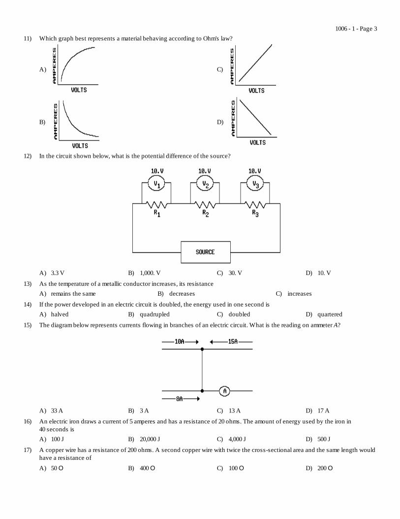
11) Which graph best represents a material behaving according to Ohm's law?
A)
B)
C)
D)
12) In the circuit shown below, what is the potential difference of the source?
A) 3.3 V B) 1,000. V C) 30. V D) 10. V
13) As the temperature of a metallic conductor increases, its resistanceA) remains the same B) decreases C) increases
14) If the power developed in an electric circuit is doubled, the energy used in one second isA) halved B) quadrupled C) doubled D) quartered
15) The diagram below represents currents flowing in branches of an electric circuit. What is the reading on ammeter A?
A) 33 A B) 3 A C) 13 A D) 17 A
16) An electric iron draws a current of 5 amperes and has a resistance of 20 ohms. The amount of energy used by the iron in40 seconds isA) 100 J B) 20,000 J C) 4,000 J D) 500 J
17) A copper wire has a resistance of 200 ohms. A second copper wire with twice the cross-sectional area and the same length wouldhave a resistance ofA) 50 O B) 400 O C) 100 O D) 200 O
1006 - 1 - Page 3

18) At room temperature, which segment of copper wire has the highest resistance?
A) 1.0 m length, 1.0 x 10⁻⁶ m2 cross-sectional areaB) 2.0 m length, 1.0 x 10⁻⁶ m2 cross-sectional area
C) 2.0 m length, 3.0 x 10⁻⁶ m2 cross-sectional areaD) 1.0 m length, 3.0 x 10⁻⁶ m2 cross-sectional area
19) Three resistors of 20. ohms, 30. ohms, and 60. ohms, respectively, are connected in series with a battery. A current of 2.0 ampereswill flow through this circuit when the potential difference of the battery isA) 110 V B) 20. V C) 220 V D) 10. V
20) The ratio of the potential difference across a metallic conductor is known asA) potential dropB) resistance
C) electromagnetic forceD) conductivity
21) Which circuit segment has an equivalent resistance of 6 ohms?
A)
B)
C)
D)
22) Which graph represents a circuit element at constant temperature that obeys Ohm's law?
A) B) C) D)
23) As more resistors are added in series across a battery, the potential drop across each resistorA) decreases B) remains the same C) increases
24) Which diagram below shows correct current direction in a circuit segment?
A) B) C) D)
25) If the length of a copper wire is reduced by half, then the resistance of the wire will beA) quadrupled B) quartered C) doubled D) halved
Questions 26 through 28 refer to the following:
1006 - 1 - Page 4

26) The current in ammeter A isA) 6.0 amperes B) 2.0 amperes C) 8.0 amperes D) 1.0 amperes
27) If resistance R2 were removed, the current in ammeter A would
A) remain the same B) increase C) decrease
28) If resistance R2 were removed, the potential difference across R1 would
A) increase B) decrease C) remain the same
29) Which circuit below would have the lowest voltmeter reading?
A)
B)
C)
D)
30) A flow rate of 1 coulomb per 0.1 second is measured in a wire. What is the electrical current in the wire?A) 100 A B) 0.1 A C) 1 A D) 10 A
31) In the diagram below, which of the switches must be closed in order for the lamp to light?
A) both A and B B) B, only C) A, only
1006 - 1 - Page 5

32) The circuit diagram below represents a solenoid in series with a variable resistor and a voltage source.
The resistance of the circuit isA) 72 O B) 8.0 O C) 12 O D) 24 O
33) A 10-volt potential difference maintains a 2-ampere current in a resistor. The total energy expended by this resistor in 5 secondsisA) 50 J B) 20 J C) 10 J D) 100 J
34) An electric current in a metallic solid consists of movingA) neutrons B) protons C) electrons D) nuclei
35) A toaster connected to a 120-volt outlet draws a current of 6.0 amperes. How much electrical energy does the toaster use in5.0 seconds?
A) 2.2 x 10⁴ J B) 7.2 x 10² J C) 1.4 x 10² J D) 3.6 x 10³ J
36) Three resistances of 2 ohms, 4 ohms, and 6 ohms are connected in parallel. The equivalent resistance of the three resistors isA) greater than 6 ohmsB) less than 2 ohms
C) between 4 ohms and 6 ohmsD) between 2 ohms and 4 ohms
37) If the diameter of a wire were to increase, its electrical resistance wouldA) decrease B) remain the same C) increase
38) What is the current in ammeter A in the diagram below?
A) ! A B) 9 A C) 3 A D) 1 A
1006 - 1 - Page 6

39) The diagram below represents a series circuit containing three resistors.
What is the current through resistor R2?
A) 9.0 A B) 3.0 A C) 0.33 A D) 1.0 A
40) As the resistance of a constant-voltage circuit is increased, the power developed in the circuitA) decreases B) remains the same C) increases
41) The diagram below represents an electrical circuit.
The potential difference across R2 is
A) 10. V B) 2.0 V C) 12 V D) 1.0 V
42) If both the cross-sectional area and the length of a metallic conductor were doubled, the resistance of the conductor would beA) unchanged B) quadrupled C) halved D) doubled
43) While operating at 120 volts, an electric toaster has a resistance of 15 ohms. The power used by the toaster isA) 1,800 W B) 120 W C) 8.0 W D) 960 W
44) A charge of 5.0 coulombs moves through a circuit in 0.50 second. How much current is flowing through the circuit?A) 2.5 A B) 10. A C) 7.0 A D) 5.0 A
45) What is the current in the circuit represented in the diagram below?
A) 2 A B) 6 A C) 1 A D) 3 A
1006 - 1 - Page 7
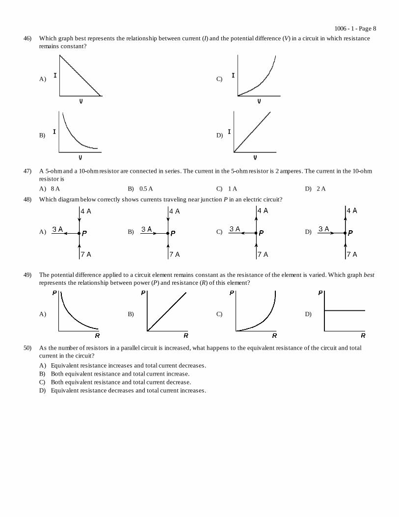
46) Which graph best represents the relationship between current (I) and the potential difference (V) in a circuit in which resistanceremains constant?
A)
B)
C)
D)
47) A 5-ohm and a 10-ohm resistor are connected in series. The current in the 5-ohm resistor is 2 amperes. The current in the 10-ohmresistor isA) 8 A B) 0.5 A C) 1 A D) 2 A
48) Which diagram below correctly shows currents traveling near junction P in an electric circuit?
A) B) C) D)
49) The potential difference applied to a circuit element remains constant as the resistance of the element is varied. Which graph bestrepresents the relationship between power (P) and resistance (R) of this element?
A) B) C) D)
50) As the number of resistors in a parallel circuit is increased, what happens to the equivalent resistance of the circuit and totalcurrent in the circuit?A) Equivalent resistance increases and total current decreases.B) Both equivalent resistance and total current increase.C) Both equivalent resistance and total current decrease.D) Equivalent resistance decreases and total current increases.
1006 - 1 - Page 8
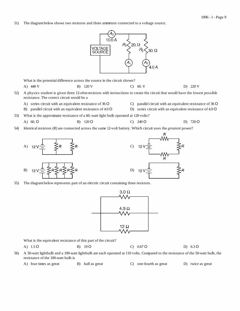
51) The diagram below shows two resistors and three ammeters connected to a voltage source.
What is the potential difference across the source in the circuit shown?A) 440 V B) 120 V C) 60. V D) 220 V
52) A physics student is given three 12-ohm resistors with instructions to create the circuit that would have the lowest possibleresistance. The correct circuit would be aA) series circuit with an equivalent resistance of 36 OB) parallel circuit with an equivalent resistance of 4.0 O
C) parallel circuit with an equivalent resistance of 36 OD) series circuit with an equivalent resistance of 4.0 O
53) What is the approximate resistance of a 60.-watt light bulb operated at 120 volts?A) 60. O B) 120 O C) 240 O D) 720 O
54) Identical resistors (R) are connected across the same 12-volt battery. Which circuit uses the greatest power?
A)
B)
C)
D)
55) The diagram below represents part of an electric circuit containing three resistors.
What is the equivalent resistance of this part of the circuit?A) 1.5 O B) 19 O C) 0.67 O D) 6.3 O
56) A 50-watt lightbulb and a 100-watt lightbulb are each operated at 110 volts. Compared to the resistance of the 50-watt bulb, theresistance of the 100-watt bulb isA) four times as great B) half as great C) one-fourth as great D) twice as great
1006 - 1 - Page 9

57) In which circuit would ammeter A show the greatest current?
A)
B)
C)
D)
58) A 30.-ohm resistor and a 60.-ohm resistor are connected in an electric circuit as shown below.
Compared to the electric current through the 30.-ohm resistor, the electric current through the 60.-ohm resistor isA) the same B) larger C) smaller
59) An incandescent light bulb is supplied with a constant potential difference of 120 volts. As the filament of the bulb heats up, itsresistanceA) decreases and the current through it increasesB) increases and the current through it decreases
C) decreases and the current through it decreasesD) increases and the current through it increases
Questions 60 and 61 refer to the following:
60) If switch S1 in the given diagram is closed, the equivalent resistance of the circuit is
A) 8.0 O B) 16 O C) 3.0 O D) 2.0 O
61) If switch S1 in the given diagram is open, the reading of ammeter A is
A) 0.50 A B) 2.0 A C) 6.0 A D) 1.5 A
1006 - 1 - Page 10

Questions 62 and 63 refer to the following:
A 20.-ohm resistor and a 30.-ohm resistor are connected in parallel to a 12-volt battery as shown. An ammeter is connected as shown.
62) What is the power of the 30.-ohm resistor?A) 75 W B) 4.8 W C) 12 W D) 30. W
63) What is the current reading of the ammeter?A) 1.0 A B) 0.20 A C) 0.60 A D) 0.40 A
64) A 330.-ohm resistor is connected to a 5.00-volt battery. What is the current through the resistor?A) 15.2 mA B) 1,650 mA C) 0.152 mA D) 335 mA
65) The graph below represents the relationship between the potential difference (V) across a resistor and the current (I) through theresistor.
Through which entire interval does the resistor obey Ohm's law?A) AB B) BC C) AD D) CD
66) A 6.0-ohm resistor that obeys Ohm's Law is connected to a source of variable potential difference. When the applied voltage isdecreased from 12 V to 6.0 V, the current passing through the resistorA) remains the same B) is quadrupled C) is halved D) is doubled
67) A potential drop of 50. volts is measured across a 250-ohm resistor. What is the power developed in the resistor?A) 50. W B) 5.0 W C) 0.20 W D) 10. W
68) Which diagram shows correct current direction in a segment of an electric circuit?
A)
B)
C)
D)
1006 - 1 - Page 11

69) What must be inserted between points A and B to establish a steady electric current in the incomplete circuit represented in thediagram below?
A) source of potential differenceB) magnetic field source
C) switchD) voltmeter
70) The diagram below shows two resistors connected in parallel across a 6.0-volt source.
Compared to the power dissipated in the 1.0-ohm resistor, the power dissipated in the 3.0-ohm resistor isA) less B) the same C) greater
71) If a 15-ohm resistor is connected in parallel with a 30.-ohm resistor, what is the equivalent resistance?A) 45 O B) 10. O C) 2.0 O D) 15 O
72) One watt is equivalent to oneA) N/m B) Jds C) Ndm D) J/s
73) The diagram below shows a circuit with two resistors.
What is the reading on ammeter A?A) 0.75 A B) 1.5 A C) 1.3 A D) 3.0 A
74) How much current flows through a 12-ohm flashlight bulb operating at 3.0 volts?A) 4.0 A B) 0.75 A C) 3.0 A D) 0.25 A
1006 - 1 - Page 12

75) The graph below shows the relationship between the potential difference across a metallic conductor and the electric currentthrough the conductor at constant temperature T1.
Which graph best represents the relationship between potential difference and current for the same conductor maintained at ahigher constant temperature, T2?
A)
B)
C)
D)
76) Two identical resistors connected in series have an equivalent resistance of 4 ohms. The same two resistors, when connected inparallel, have an equivalent resistance ofA) 4 O B) 1 O C) 8 O D) 2 O
77) While operating at 120 volts, an electric toaster has a resistance of 15 ohms. What is the power used by the toaster?A) 8.0 W B) 960 W C) 1,800 W D) 120 W
1006 - 1 - Page 13