Embed Size (px)
Citation preview
MAHARASHTRA STATE BOARD OF TECHNICAL EDUCATION
(Autonomous)
(ISO/IEC - 27001 - 2005 Certified)
WINTER – 2015 EXAMINATION
Subject Code: 17331 Model Answer Page No: 1/37
Important Instructions to examiners: 1) The answers should be examined by key words and not as word-to-word as given in the model
answer scheme.
2) The model answer and the answer written by candidate may vary but the examiner may try to
assess the understanding level of the candidate.
3) The language errors such as grammatical, spelling errors should not be given more Importance
(Not applicable for subject English and Communication Skills.
4) While assessing figures, examiner may give credit for principal components indicated in the
figure. The figures drawn by candidate and model answer may vary. The examiner may give
credit for any equivalent figure drawn.
5) Credits may be given step wise for numerical problems. In some cases, the assumed constant
values may vary and there may be some difference in the candidate‟s answers and model answer.
6) In case of some questions credit may be given by judgement on part of examiner of relevant
answer based on candidate‟s understanding.
7) For programming language papers, credit may be given to any other
program based on equivalent concept.
Q .1) A) Attempt any SIX of the following: 12
a) Define potential difference and current.
(Definition of potential difference 1M, current 1M)
Ans.
Potential difference: The difference between the electrical potentials at any two given
points in the electrical circuit is known as potential difference.
Current: The rate of flow of electric charge from a given conductor is called current.
b) State Kirchhoff’s current law.
(Statement of Kirchhoff’s current law 2M)
Ans. Kirchhoff’s current law: In any electrical network, the algebraic sum of the currents
meeting at a point (or junction) is zero.
∑
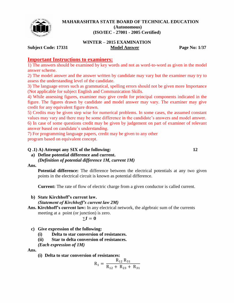
c) Give expression of the following:
(i) Delta to star conversion of resistances.
(ii) Star to delta conversion of resistances.
(Each expression of 1M)
Ans.
(i) Delta to star conversion of resistances:
MAHARASHTRA STATE BOARD OF TECHNICAL EDUCATION
(Autonomous)
(ISO/IEC - 27001 - 2005 Certified)
WINTER – 2015 EXAMINATION
Subject Code: 17331 Model Answer Page No: 2/37 OR
(ii) Star to delta conversion of resistances.
OR
d) Define the following terms:
(i) Electromagnetism.
(ii) Magnetic flux.
(Define Electromagnetism1M, Magnetic flux 1M)
Ans.
(i) Electromagnetism: The emf is induced in any conductor when the conductor cuts or is
cut by a magnetic flux is known as electromagnetism.
(ii) Magnetic flux: The amount of magnetic field produced by a magnetic source is called
magnetic flux.
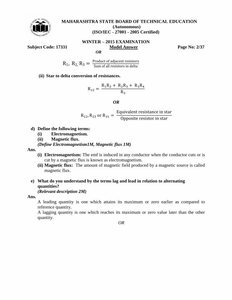
e) What do you understand by the terms lag and lead in relation to alternating
quantities?
(Relevant description 2M)
Ans. A leading quantity is one which attains its maximum or zero earlier as compared to
reference quantity.
A lagging quantity is one which reaches its maximum or zero value later than the other
quantity.
OR
MAHARASHTRA STATE BOARD OF TECHNICAL EDUCATION
(Autonomous)
(ISO/IEC - 27001 - 2005 Certified)
WINTER – 2015 EXAMINATION
Subject Code: 17331 Model Answer Page No: 3/37
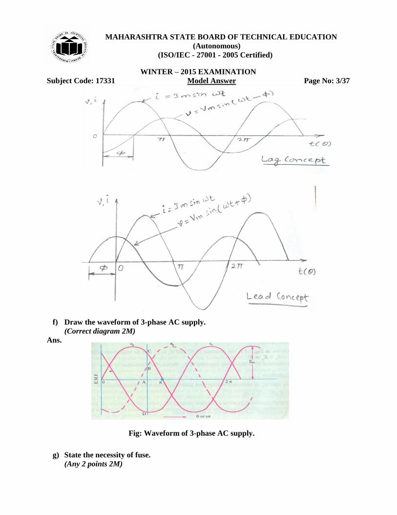
f) Draw the waveform of 3-phase AC supply.
(Correct diagram 2M)
Ans.
Fig: Waveform of 3-phase AC supply.
g) State the necessity of fuse.
(Any 2 points 2M)
MAHARASHTRA STATE BOARD OF TECHNICAL EDUCATION
(Autonomous)
(ISO/IEC - 27001 - 2005 Certified)
WINTER – 2015 EXAMINATION
Subject Code: 17331 Model Answer Page No: 4/37 Ans. (i) To safeguard electrical circuit against harmful effect of excessive currents.
(ii) To protect the electrical installation against short circuiting and earth faults.
(iii)It also helps in isolating only required part of the circuit without affecting the remaining
circuit during maintenance.
h) Give any two precautions against electric shock.
(Any 2 points 2M)
Ans.
Precautions against electric shock:
1) While using any electrical device put on rubber sole footwear and keep your hands dry.
2) Always switch off main switch before replacing a blown fuse.
3) Electrical equipment should be properly earthed.
Q .1) B) Attempt any TWO of the following: 8
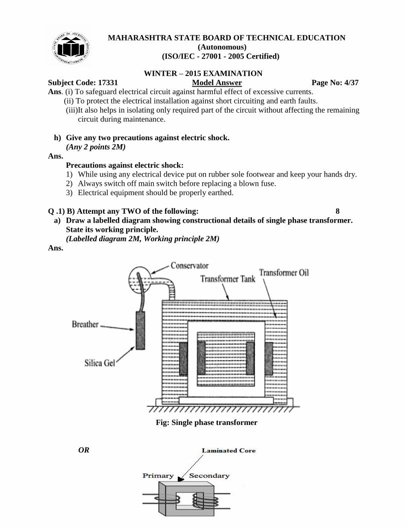
a) Draw a labelled diagram showing constructional details of single phase transformer.
State its working principle.
(Labelled diagram 2M, Working principle 2M)
Ans.
Fig: Single phase transformer
OR
MAHARASHTRA STATE BOARD OF TECHNICAL EDUCATION
(Autonomous)
(ISO/IEC - 27001 - 2005 Certified)
WINTER – 2015 EXAMINATION
Subject Code: 17331 Model Answer Page No: 5/37
Working principle of single phase transformer:
(i) When the primary winding is connected to AC supply, an AC current starts flowing
through it.
(ii) The AC primary current produces an alternating flux ϕ in the core.
(iii) The changing flux will induce voltage in the secondary winding due to mutual
induction and the emf is induced in the secondary called as mutually induced emf.
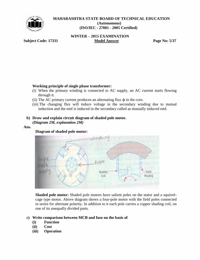
b) Draw and explain circuit diagram of shaded pole motor.
(Diagram 2M, explanation 2M)
Ans.
Diagram of shaded pole motor:
Shaded pole motor: Shaded pole motors have salient poles on the stator and a squirrel-
cage type motor. Above diagram shows a four-pole motor with the field poles connected
in series for alternate polarity. In addition to it each pole carries a copper shading coil, on
one of its unequally divided parts.
c) Write comparison between MCB and fuse on the basis of
(i) Function
(ii) Cost
(iii) Operation
MAHARASHTRA STATE BOARD OF TECHNICAL EDUCATION
(Autonomous)
(ISO/IEC - 27001 - 2005 Certified)
WINTER – 2015 EXAMINATION
Subject Code: 17331 Model Answer Page No: 6/37 (iv) Safety
(Each point 1M)
Ans.
Sr.No. Parameter Fuse MCB
1 Function Performs both detection and interrupt function
Performs Interruption only. Detection is made by relay system
2 Cost Relatively cheaper Costlier when compared to fuse.
3 Operation Completely automatic Requires separate automatic action
4 Safety Use for protection against small circuit and over current.
Use for protection against over current for large circuit.
Q .2) Attempt any FOUR of the following: 16
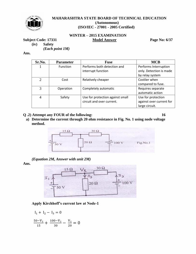
a) Determine the current through 20 ohm resistance in Fig. No. 1 using node voltage
method.
(Equation 2M, Answer with unit 2M)
Ans.
Apply Kirchhoff’s current law at Node-1
MAHARASHTRA STATE BOARD OF TECHNICAL EDUCATION
(Autonomous)
(ISO/IEC - 27001 - 2005 Certified)
WINTER – 2015 EXAMINATION
Subject Code: 17331 Model Answer Page No: 7/37
=
= 3
Current through 20 ohm resistance,
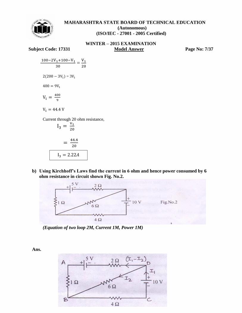
b) Using Kirchhoff’s Laws find the current in 6 ohm and hence power consumed by 6
ohm resistance in circuit shown Fig. No.2.
(Equation of two loop 2M, Current 1M, Power 1M)
Ans.
𝐴
MAHARASHTRA STATE BOARD OF TECHNICAL EDUCATION
(Autonomous)
(ISO/IEC - 27001 - 2005 Certified)
WINTER – 2015 EXAMINATION
Subject Code: 17331 Model Answer Page No: 8/37
Consider loop ABDA,
Applying KVL,
…………………………………………………………….(1)
Consider loop BCDB,
Applying KVL,
……………………………………………………………….(2)
Solving equation (1) and (2),
12
12
Power,
6 = 0.1944W
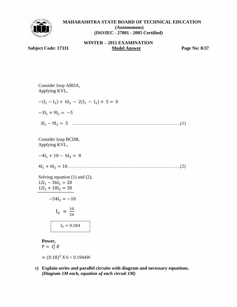
c) Explain series and parallel circuits with diagram and necessary equations.
(Diagram 1M each, equation of each circuit 1M)
𝐴
MAHARASHTRA STATE BOARD OF TECHNICAL EDUCATION
(Autonomous)
(ISO/IEC - 27001 - 2005 Certified)
WINTER – 2015 EXAMINATION
Subject Code: 17331 Model Answer Page No: 9/37 Ans.
Series circuit diagram:
Equation:
Total voltage in series circuit,
Equivalent resistance,
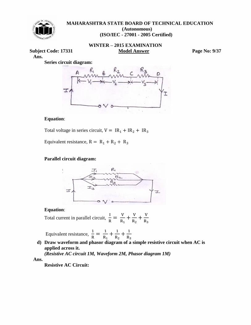
Parallel circuit diagram:
Equation:
Total current in parallel circuit,
Equivalent resistance,
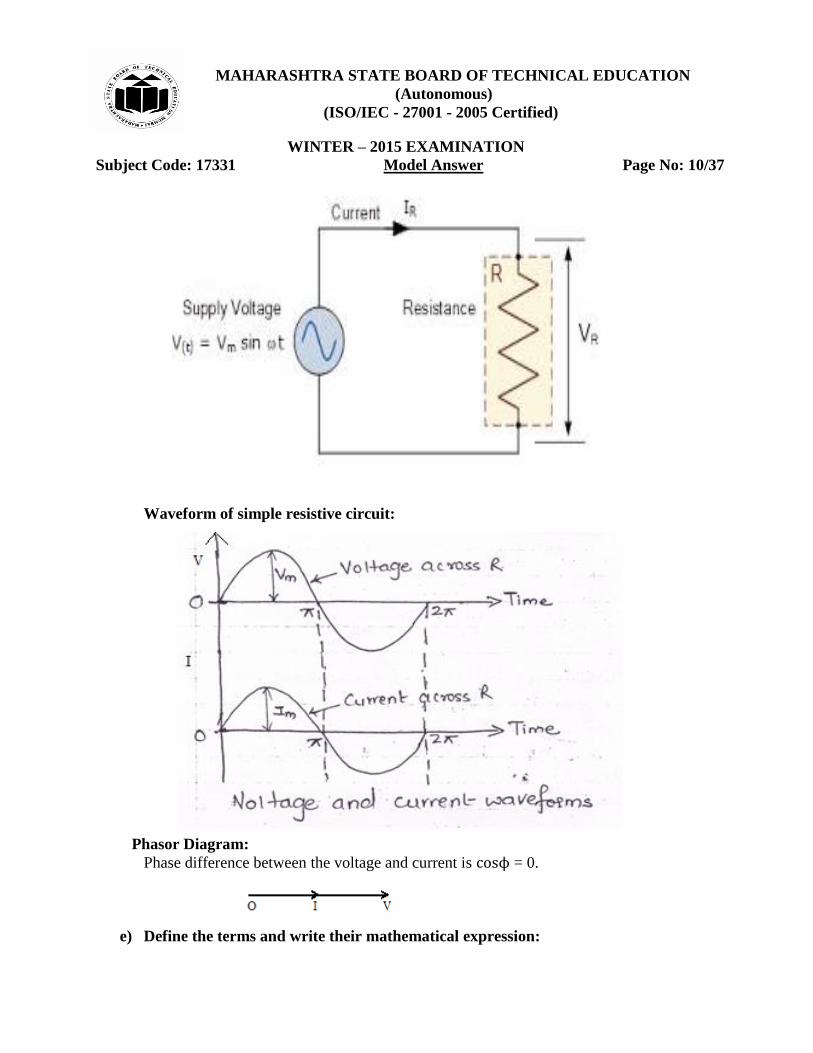
d) Draw waveform and phasor diagram of a simple resistive circuit when AC is
applied across it.
(Resistive AC circuit 1M, Waveform 2M, Phasor diagram 1M)
Ans.
Resistive AC Circuit:
MAHARASHTRA STATE BOARD OF TECHNICAL EDUCATION
(Autonomous)
(ISO/IEC - 27001 - 2005 Certified)
WINTER – 2015 EXAMINATION
Subject Code: 17331 Model Answer Page No: 10/37
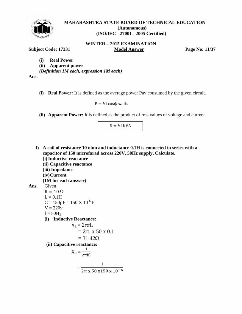
Waveform of simple resistive circuit:
Phasor Diagram:
Phase difference between the voltage and current is ϕ = 0.
e) Define the terms and write their mathematical expression:
MAHARASHTRA STATE BOARD OF TECHNICAL EDUCATION
(Autonomous)
(ISO/IEC - 27001 - 2005 Certified)
WINTER – 2015 EXAMINATION
Subject Code: 17331 Model Answer Page No: 11/37
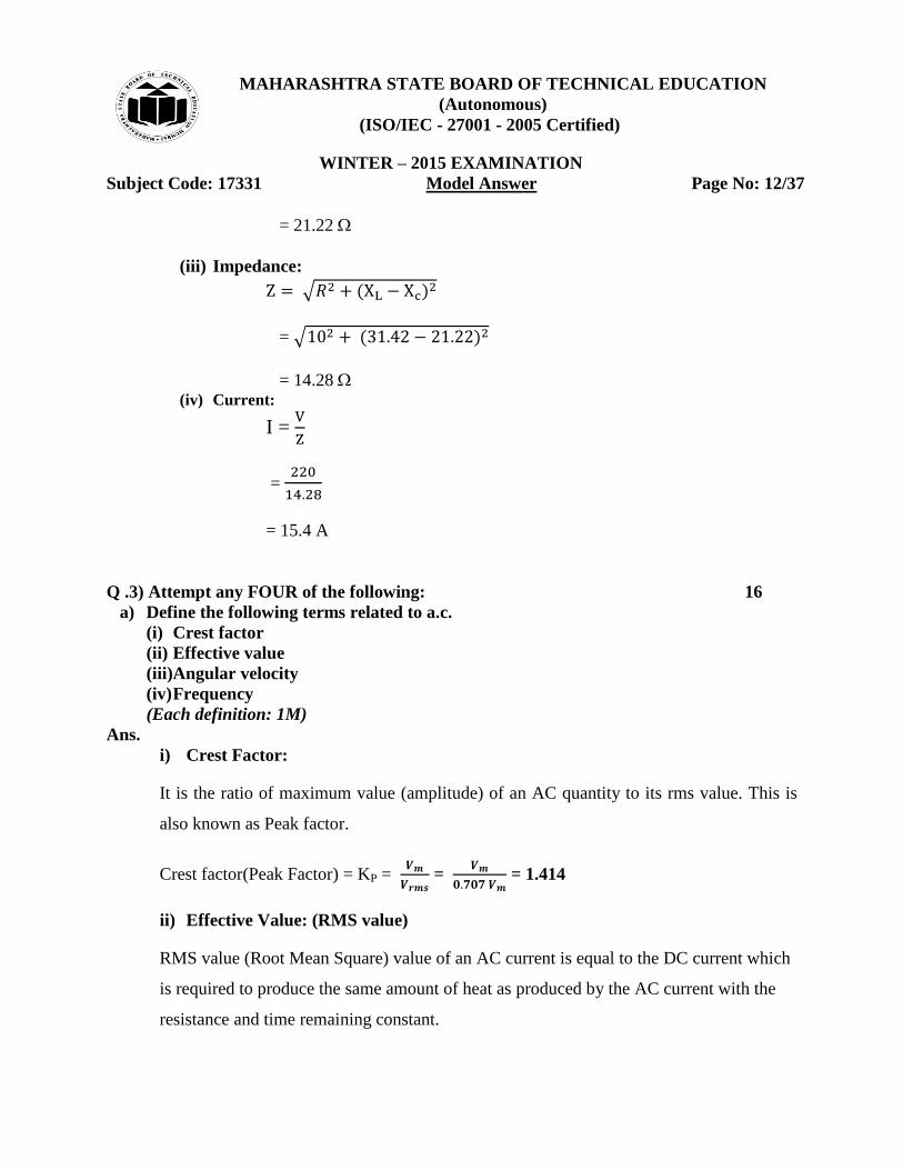
(i) Real Power
(ii) Apparent power
(Definition 1M each, expression 1M each)
Ans.
(i) Real Power: It is defined as the average power Pav consumed by the given circuit.
(ii) Apparent Power: It is defined as the product of rms values of voltage and current.
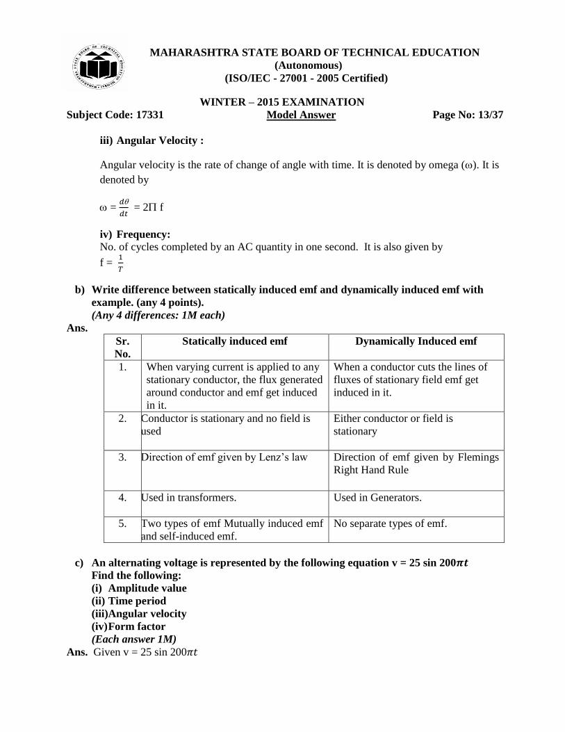
f) A coil of resistance 10 ohm and inductance 0.1H is connected in series with a
capacitor of 150 microfarad across 220V, 50Hz supply, Calculate.
(i) Inductive reactance
(ii) Capacitive reactance
(iii) Impedance
(iv) Current
(1M for each answer)
Ans. Given
L = 0.1H
C = 150µF = 150 X 10-6
F
V = 220v
f = 50HZ
(i) Inductive Reactance:
XL =
= x 50 x 0.1
= 31.42 (ii) Capacitive reactance:
XC =
=
ϕ watts
K A
MAHARASHTRA STATE BOARD OF TECHNICAL EDUCATION
(Autonomous)
(ISO/IEC - 27001 - 2005 Certified)
WINTER – 2015 EXAMINATION
Subject Code: 17331 Model Answer Page No: 12/37
= 21.22
(iii) Impedance:
√
= √
= 14.28 (iv) Current:
I =
=
= 15.4 A
Q .3) Attempt any FOUR of the following: 16
a) Define the following terms related to a.c.
(i) Crest factor
(ii) Effective value
(iii)Angular velocity
(iv) Frequency
(Each definition: 1M)
Ans.
i) Crest Factor:
It is the ratio of maximum value (amplitude) of an AC quantity to its rms value. This is
also known as Peak factor.
Crest factor(Peak Factor) = KP =
=
= 1.414
ii) Effective Value: (RMS value)
RMS value (Root Mean Square) value of an AC current is equal to the DC current which
is required to produce the same amount of heat as produced by the AC current with the
resistance and time remaining constant.
MAHARASHTRA STATE BOARD OF TECHNICAL EDUCATION
(Autonomous)
(ISO/IEC - 27001 - 2005 Certified)
WINTER – 2015 EXAMINATION
Subject Code: 17331 Model Answer Page No: 13/37
iii) Angular Velocity :
Angular velocity is the rate of change of angle with time. It is denoted by omega (). It is
denoted by
=
= 2 f
iv) Frequency:
No. of cycles completed by an AC quantity in one second. It is also given by
f =
b) Write difference between statically induced emf and dynamically induced emf with
example. (any 4 points).
(Any 4 differences: 1M each)
Ans.
Sr.
No.
Statically induced emf Dynamically Induced emf
1. When varying current is applied to any
stationary conductor, the flux generated
around conductor and emf get induced
in it.
When a conductor cuts the lines of
fluxes of stationary field emf get
induced in it.
2. Conductor is stationary and no field is
used
Either conductor or field is
stationary
3. Direction of emf given by Lenz‟s law
Direction of emf given by Flemings
Right Hand Rule
4. Used in transformers.
Used in Generators.
5. Two types of emf Mutually induced emf
and self-induced emf.
No separate types of emf.
c) An alternating voltage is represented by the following equation v = 25 sin 200 Find the following:
(i) Amplitude value
(ii) Time period
(iii)Angular velocity
(iv) Form factor
(Each answer 1M)
Ans. Given v = 25 sin 200
MAHARASHTRA STATE BOARD OF TECHNICAL EDUCATION
(Autonomous)
(ISO/IEC - 27001 - 2005 Certified)
WINTER – 2015 EXAMINATION
Subject Code: 17331 Model Answer Page No: 14/37
Vm= 25 volts w = 200
(i) Amplitude value: vm= 25 volts
(ii) Time period:
w = 2 = 200
2 = 200
= 100
T =
=
= 0.01 sec
(iii) Angular velocity:
w = 2
= 200
= 628.39 rad/sec
(iv) Form Factor:
Form Factor =
=
= 1.11
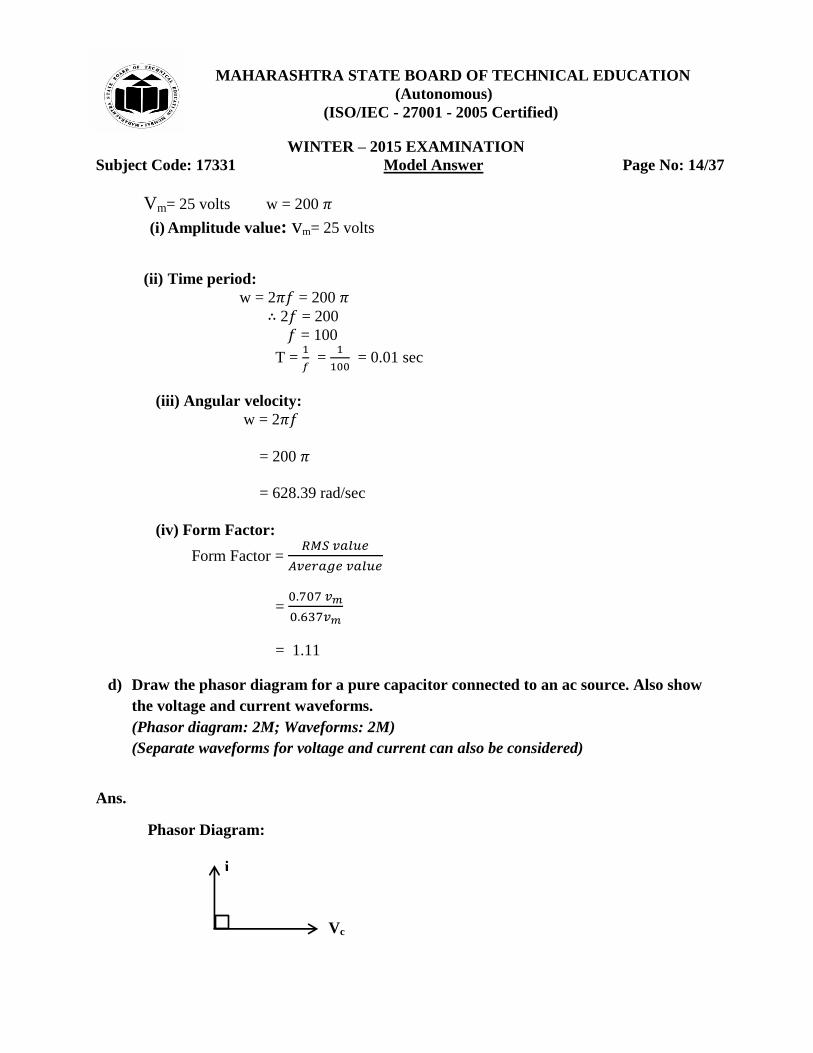
d) Draw the phasor diagram for a pure capacitor connected to an ac source. Also show
the voltage and current waveforms.
(Phasor diagram: 2M; Waveforms: 2M)
(Separate waveforms for voltage and current can also be considered)
Ans.
Phasor Diagram:
i
Vc
MAHARASHTRA STATE BOARD OF TECHNICAL EDUCATION
(Autonomous)
(ISO/IEC - 27001 - 2005 Certified)
WINTER – 2015 EXAMINATION
Subject Code: 17331 Model Answer Page No: 15/37
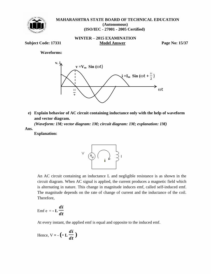
i =Im Sin (t + )
v =Vm Sin (t)
𝟐
t
v, i
Waveforms:
e) Explain behavior of AC circuit containing inductance only with the help of waveform
and vector diagram.
(Waveform: 1M; vector diagram: 1M; circuit diagram: 1M; explanation: 1M)
Ans.
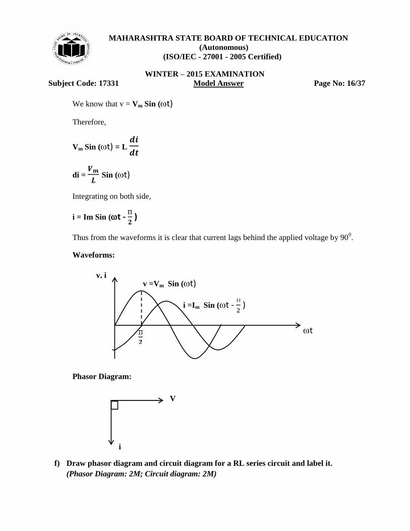
Explanation:
An AC circuit containing an inductance L and negligible resistance is as shown in the
circuit diagram. When AC signal is applied, the current produces a magnetic field which
is alternating in nature. This change in magnitude induces emf, called self-induced emf.
The magnitude depends on the rate of change of current and the inductance of the coil.
Therefore,
Emf e = - L
At every instant, the applied emf is equal and opposite to the induced emf.
Hence, V = - (- L
)
MAHARASHTRA STATE BOARD OF TECHNICAL EDUCATION
(Autonomous)
(ISO/IEC - 27001 - 2005 Certified)
WINTER – 2015 EXAMINATION
Subject Code: 17331 Model Answer Page No: 16/37
i
V
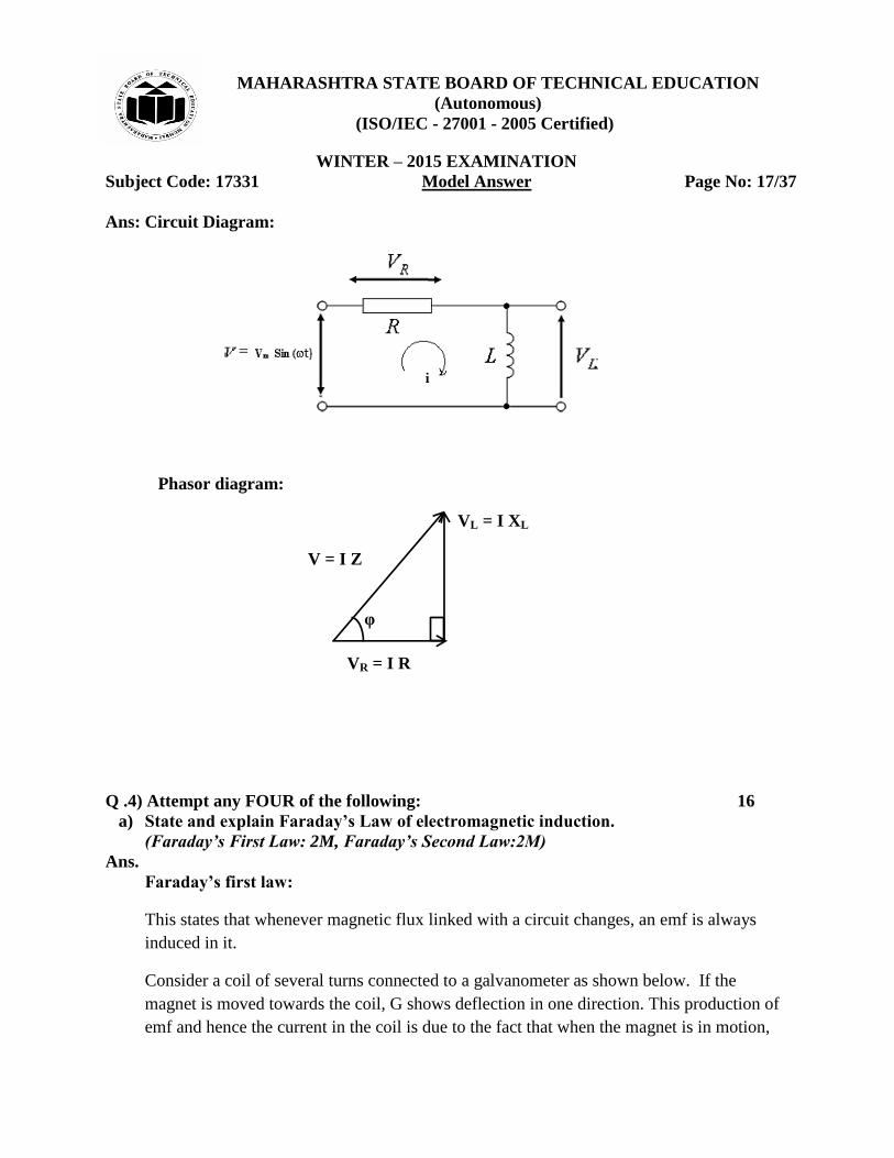
We know that v = Vm Sin (t)
Therefore,
Vm Sin (t) = L
di =
Sin (t)
Integrating on both side,
i = Im Sin (t -
)
Thus from the waveforms it is clear that current lags behind the applied voltage by 900.
Waveforms:
Phasor Diagram:
f) Draw phasor diagram and circuit diagram for a RL series circuit and label it.
(Phasor Diagram: 2M; Circuit diagram: 2M)
i =Im Sin (t - )
v =Vm Sin (t)
𝟐
t
v, i
MAHARASHTRA STATE BOARD OF TECHNICAL EDUCATION
(Autonomous)
(ISO/IEC - 27001 - 2005 Certified)
WINTER – 2015 EXAMINATION
Subject Code: 17331 Model Answer Page No: 17/37
Ans: Circuit Diagram:
Phasor diagram:
Q .4) Attempt any FOUR of the following: 16
a) State and explain Faraday’s Law of electromagnetic induction.
(Faraday’s First Law: 2M, Faraday’s Second Law:2M)
Ans.
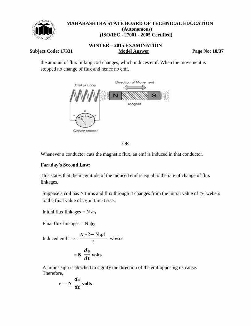
Faraday’s first law:
This states that whenever magnetic flux linked with a circuit changes, an emf is always
induced in it.
Consider a coil of several turns connected to a galvanometer as shown below. If the
magnet is moved towards the coil, G shows deflection in one direction. This production of
emf and hence the current in the coil is due to the fact that when the magnet is in motion,
φ
VR = I R
VL = I XL
V = I Z
MAHARASHTRA STATE BOARD OF TECHNICAL EDUCATION
(Autonomous)
(ISO/IEC - 27001 - 2005 Certified)
WINTER – 2015 EXAMINATION
Subject Code: 17331 Model Answer Page No: 18/37
the amount of flux linking coil changes, which induces emf. When the movement is
stopped no change of flux and hence no emf.
OR
Whenever a conductor cuts the magnetic flux, an emf is induced in that conductor.
Faraday’s Second Law:
This states that the magnitude of the induced emf is equal to the rate of change of flux
linkages.
Suppose a coil has N turns and flux through it changes from the initial value of ϕ1 webers
to the final value of ϕ2 in time t secs.
Initial flux linkages = N ϕ1
Final flux linkages = N ϕ2
Induced emf = e = ϕ ϕ
wb/sec
= N ϕ
volts
A minus sign is attached to signify the direction of the emf opposing its cause.
Therefore,
e= - N ϕ
volts
MAHARASHTRA STATE BOARD OF TECHNICAL EDUCATION
(Autonomous)
(ISO/IEC - 27001 - 2005 Certified)
WINTER – 2015 EXAMINATION
Subject Code: 17331 Model Answer Page No: 19/37
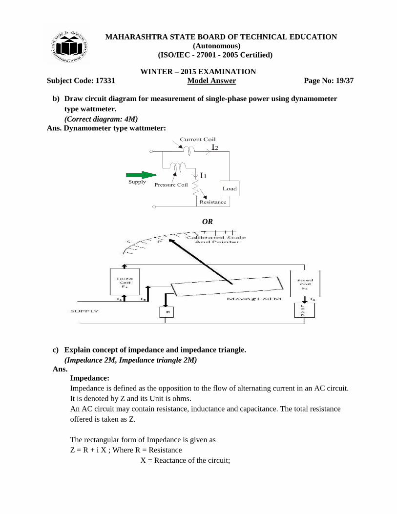
b) Draw circuit diagram for measurement of single-phase power using dynamometer
type wattmeter.
(Correct diagram: 4M)
Ans. Dynamometer type wattmeter:
OR
c) Explain concept of impedance and impedance triangle.
(Impedance 2M, Impedance triangle 2M)
Ans.
Impedance:
Impedance is defined as the opposition to the flow of alternating current in an AC circuit.
It is denoted by Z and its Unit is ohms.
An AC circuit may contain resistance, inductance and capacitance. The total resistance
offered is taken as Z.
The rectangular form of Impedance is given as
Z = R + i X ; Where R = Resistance
X = Reactance of the circuit;
MAHARASHTRA STATE BOARD OF TECHNICAL EDUCATION
(Autonomous)
(ISO/IEC - 27001 - 2005 Certified)
WINTER – 2015 EXAMINATION
Subject Code: 17331 Model Answer Page No: 20/37
The magnitude of Z = | | = √
The phase angle ϕ = tan-1
= (
)
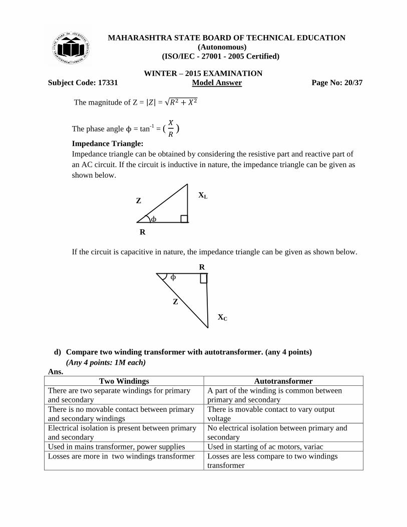
Impedance Triangle:
Impedance triangle can be obtained by considering the resistive part and reactive part of
an AC circuit. If the circuit is inductive in nature, the impedance triangle can be given as
shown below.
If the circuit is capacitive in nature, the impedance triangle can be given as shown below.
d) Compare two winding transformer with autotransformer. (any 4 points)
(Any 4 points: 1M each)
Ans.
Two Windings Autotransformer
There are two separate windings for primary
and secondary
A part of the winding is common between
primary and secondary
There is no movable contact between primary
and secondary windings
There is movable contact to vary output
voltage
Electrical isolation is present between primary
and secondary
No electrical isolation between primary and
secondary
Used in mains transformer, power supplies Used in starting of ac motors, variac
Losses are more in two windings transformer Losses are less compare to two windings
transformer
ϕ
R
XL Z
ϕ
R
XC
Z
MAHARASHTRA STATE BOARD OF TECHNICAL EDUCATION
(Autonomous)
(ISO/IEC - 27001 - 2005 Certified)
WINTER – 2015 EXAMINATION
Subject Code: 17331 Model Answer Page No: 21/37
Efficiency is less as compare to
autotransformer
Efficiency is more as compare to two winding
transformer
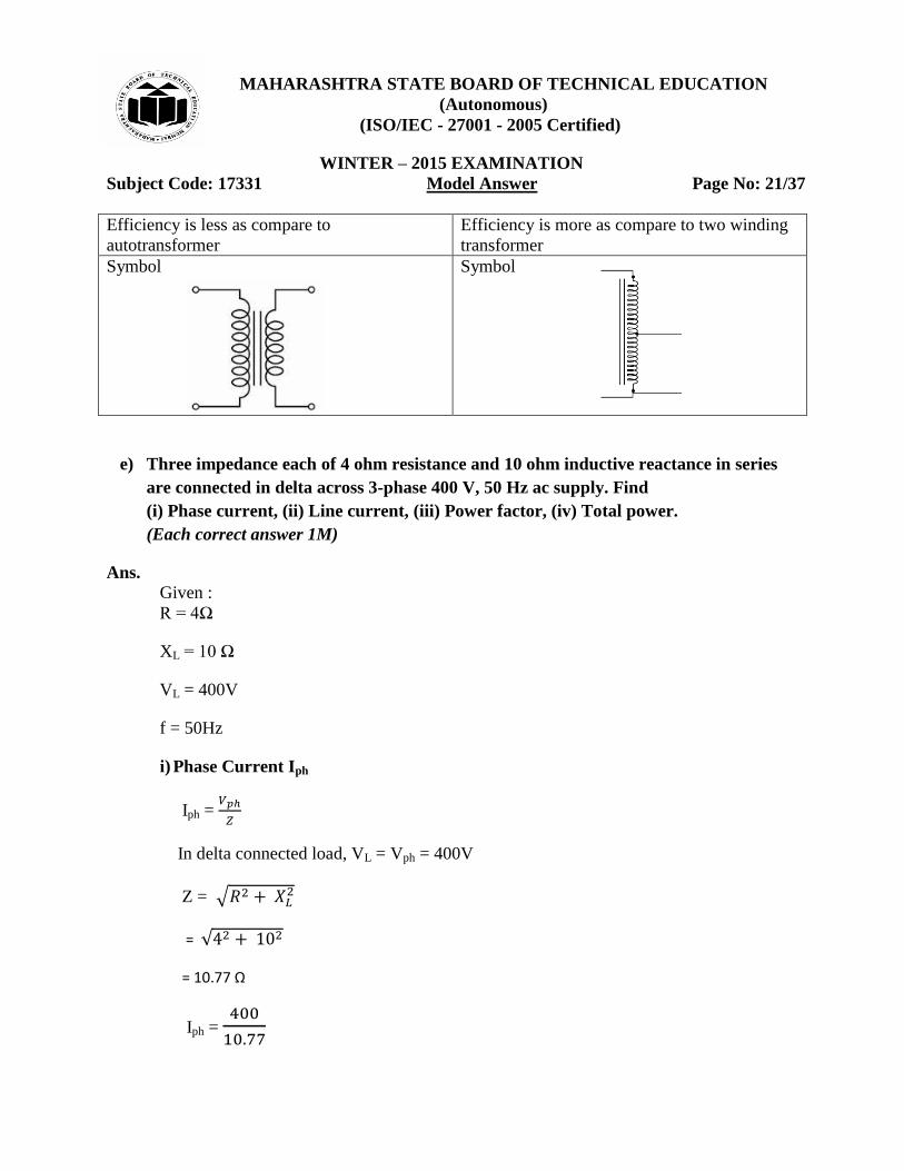
Symbol
Symbol
e) Three impedance each of 4 ohm resistance and 10 ohm inductive reactance in series
are connected in delta across 3-phase 400 V, 50 Hz ac supply. Find
(i) Phase current, (ii) Line current, (iii) Power factor, (iv) Total power.
(Each correct answer 1M)
Ans.
Given :
R = 4Ω
XL = 10 Ω
VL = 400V
f = 50Hz
i) Phase Current Iph
Iph =
In delta connected load, VL = Vph = 400V
Z = √
= √
= 10.77 Ω
Iph =
MAHARASHTRA STATE BOARD OF TECHNICAL EDUCATION
(Autonomous)
(ISO/IEC - 27001 - 2005 Certified)
WINTER – 2015 EXAMINATION
Subject Code: 17331 Model Answer Page No: 22/37
Iph = 37.14A
ii) Line Current IL :
In delta connected load,
Line current IL = √ Iph
= √ x 37.14
IL = 64.33 A
iii) Power factor:
Power factor = cos ϕ =
=
= 0.371 Ω
iv) Total power P:
Total Power P = √ VL IL cos ϕ
= √ x 400 x 64.33 x 0.371
P = 16,535 Watts OR 16.535 KWatts
f) Define: (i) Voltage ratio, (ii) Current ratio, (iii) Turns ratio, (iv) KVA rating of a
transformer.
(Each definition: 1M)
Ans.
(i) Voltage Ratio: The ratio of primary to secondary terminal voltage is called the voltage
ratio.
Voltage Ratio =
(ii) Current ratio: The ratio of primary current to secondary current is called current
ratio.
Current Ratio =
MAHARASHTRA STATE BOARD OF TECHNICAL EDUCATION
(Autonomous)
(ISO/IEC - 27001 - 2005 Certified)
WINTER – 2015 EXAMINATION
Subject Code: 17331 Model Answer Page No: 23/37
(iii) Turns ratio: The ratio of no. of turns of primary winding to the no. of turns of the
secondary winding is called the turns ratio.
Turns Ratio =
(iv) KVA rating of a transformer:
Rating of a transformer indicates how much maximum power a transformer can supply. It
is given by,
Rating of a transformer = Primary voltage X Primary Current
= Secondary Voltage X Secondary Current
Rating in KVA = V1 I1 = V2 I2
Units of transformer ratings are Volt Ampere (VA) Or KVA (Kilo Volt Ampere)
Q.5) Attempt any FOUR of the following: 16
a) State and explain Lenz’s Law.
(Statement 2M, Explanation 2M)
Ans.
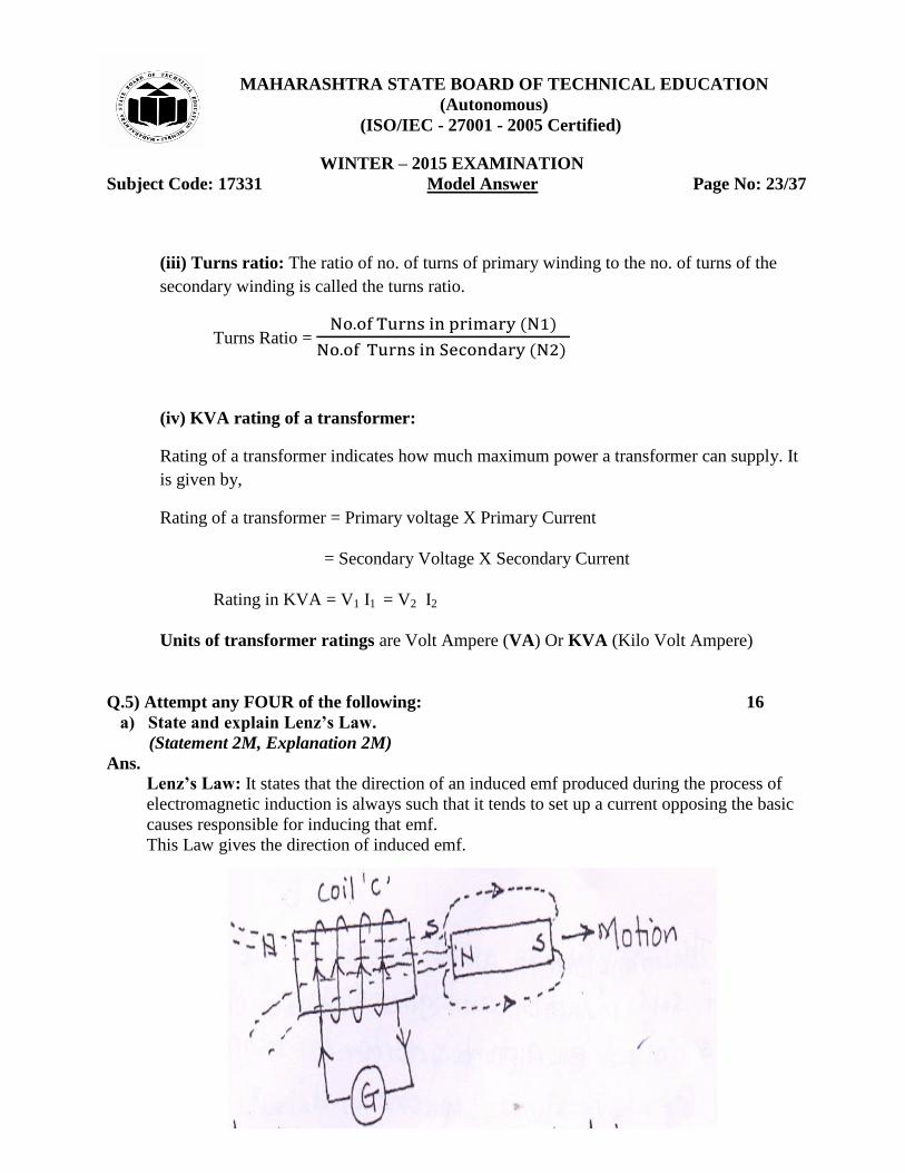
Lenz’s Law: It states that the direction of an induced emf produced during the process of
electromagnetic induction is always such that it tends to set up a current opposing the basic
causes responsible for inducing that emf.
This Law gives the direction of induced emf.
MAHARASHTRA STATE BOARD OF TECHNICAL EDUCATION
(Autonomous)
(ISO/IEC - 27001 - 2005 Certified)
WINTER – 2015 EXAMINATION
Subject Code: 17331 Model Answer Page No: 24/37
(i) Consider the coil „C‟ is connected to a galvanometer.
(ii) Assume that the magnet is being withdrawn from the coil.
(iii)The induced current in this condition will flow in such a direction that the end of the
will facing the magnet will be south pole. Thus, the force of attraction exerted by the
south pole of the coil working as an electromagnet on the north pole of the magnet will
oppose the withdrawal of the magnet from the coil.
(iv) Thus, the motion of the magnet in either direction which is responsible for inducing the
emf in the coil will be opposed by the current set up by that emf.
(v) Therefore the magnitude of induced emf is given by
ϕ
b) Explain the construction and working of Single Phase Auto Transformer.
(Diagram 1M, Construction 1 1/2M, Working 1 1/2M)
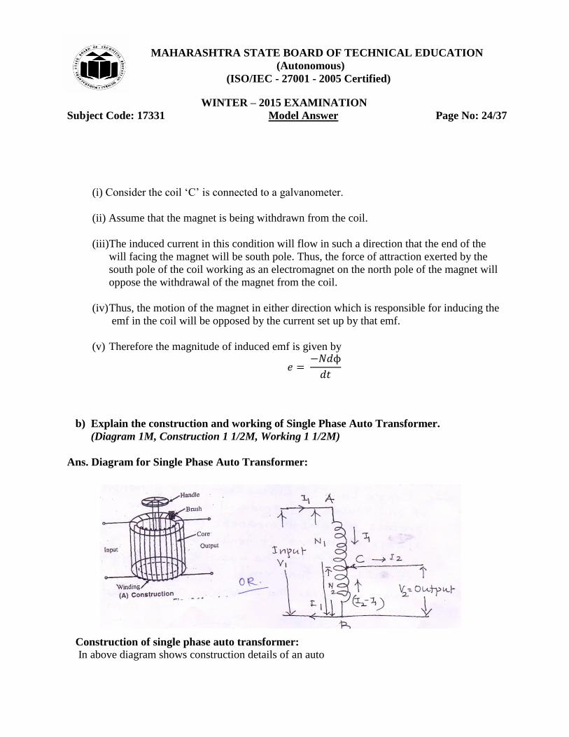
Ans. Diagram for Single Phase Auto Transformer:
Construction of single phase auto transformer:
In above diagram shows construction details of an auto
MAHARASHTRA STATE BOARD OF TECHNICAL EDUCATION
(Autonomous)
(ISO/IEC - 27001 - 2005 Certified)
WINTER – 2015 EXAMINATION
Subject Code: 17331 Model Answer Page No: 25/37
transformer.
(i) It has only one winding wound on a laminated circular magnetic core.
(ii) The core is made of silicon steel stampings.
(iii) The two terminals of the winging are connected to the supply.
(iv) A variable point on the winding is connected to a carbon brush and brush can be moved
by a circular handle.
Working of single phase auto transformer:
(i) The transformer which works on the principle of self-induction and gives variable output
voltage is called an auto transformer.
(ii) The primary winding is connected to the supply and it has N1 number of turns between
portion AB as shown in above diagram.
(iii) By moving the handle we can select N2 number of turns on the secondary i.e. between
portion BC. Thus the same winding can function as primary as well as secondary.
(iv) Hence, from the auto-transformer we can get a variable voltage by varying N2 by moving
the brush with the help of handle.
c) State four merits of three phase circuits over single phase circuits.
(Any four merits: 1M each)
Ans.
Merits of Three Phase circuits are as follows:
(i) Three phase motors are self-starting.
(ii) The output of 3 - ϕ circuits is high then 1 - ϕ circuits.
(iii)Transmission efficiency is high compared to 1 - ϕ.
(iv)The size of 3 - ϕ motor is smaller than 1 - ϕ motors of same capacity.
(v) 3 - ϕ circuits gives output voltage of 440v, 230v whereas 1 - ϕ gives 230v.
(vi)Three phase can be used in large power and industrial applications.
(vii)Power factor is better in 3 - ϕ system.
d) Explain RLC series circuit with phasor diagram.
(Series diagram 1M, Each case with phase diagram 1M)
Ans.
MAHARASHTRA STATE BOARD OF TECHNICAL EDUCATION
(Autonomous)
(ISO/IEC - 27001 - 2005 Certified)
WINTER – 2015 EXAMINATION
Subject Code: 17331 Model Answer Page No: 26/37
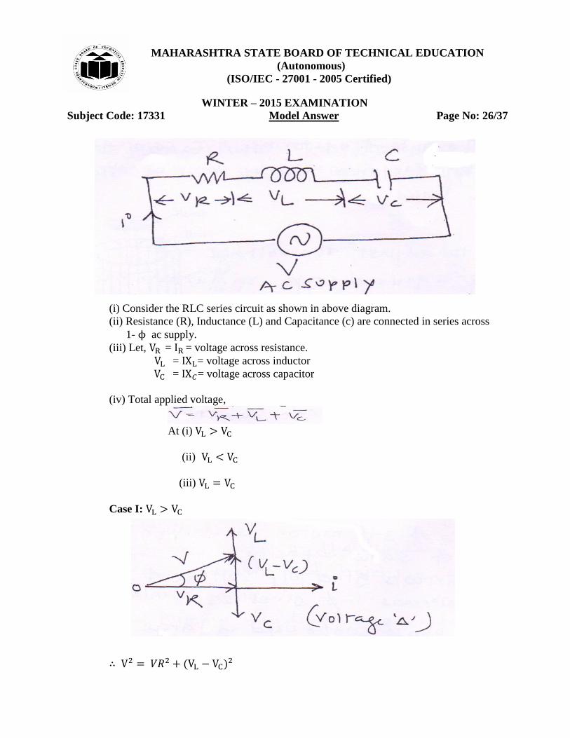
(i) Consider the RLC series circuit as shown in above diagram.
(ii) Resistance (R), Inductance (L) and Capacitance (c) are connected in series across
1- ϕ ac supply.
(iii) Let, = = voltage across resistance.
= = voltage across inductor
= = voltage across capacitor
(iv) Total applied voltage,
At (i)
(ii)
(iii)
Case I:
MAHARASHTRA STATE BOARD OF TECHNICAL EDUCATION
(Autonomous)
(ISO/IEC - 27001 - 2005 Certified)
WINTER – 2015 EXAMINATION
Subject Code: 17331 Model Answer Page No: 27/37
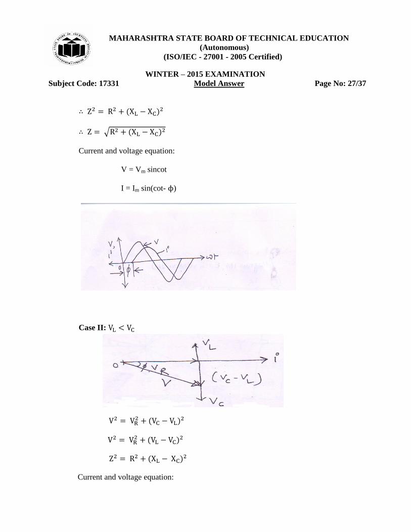
√
Current and voltage equation:
V = Vm sincot
I = Im sin(cot- ϕ)
Case II:
Current and voltage equation:
MAHARASHTRA STATE BOARD OF TECHNICAL EDUCATION
(Autonomous)
(ISO/IEC - 27001 - 2005 Certified)
WINTER – 2015 EXAMINATION
Subject Code: 17331 Model Answer Page No: 28/37
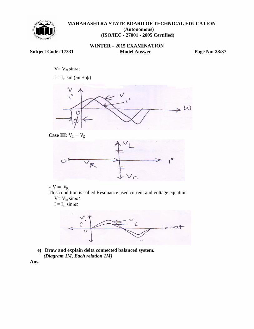
V= Vm sin t
I = Im sin ( t + ϕ)
Case III:
This condition is called Resonance used current and voltage equation
V= Vm sin I = Im sin
e) Draw and explain delta connected balanced system.
(Diagram 1M, Each relation 1M)
Ans.
MAHARASHTRA STATE BOARD OF TECHNICAL EDUCATION
(Autonomous)
(ISO/IEC - 27001 - 2005 Certified)
WINTER – 2015 EXAMINATION
Subject Code: 17331 Model Answer Page No: 29/37
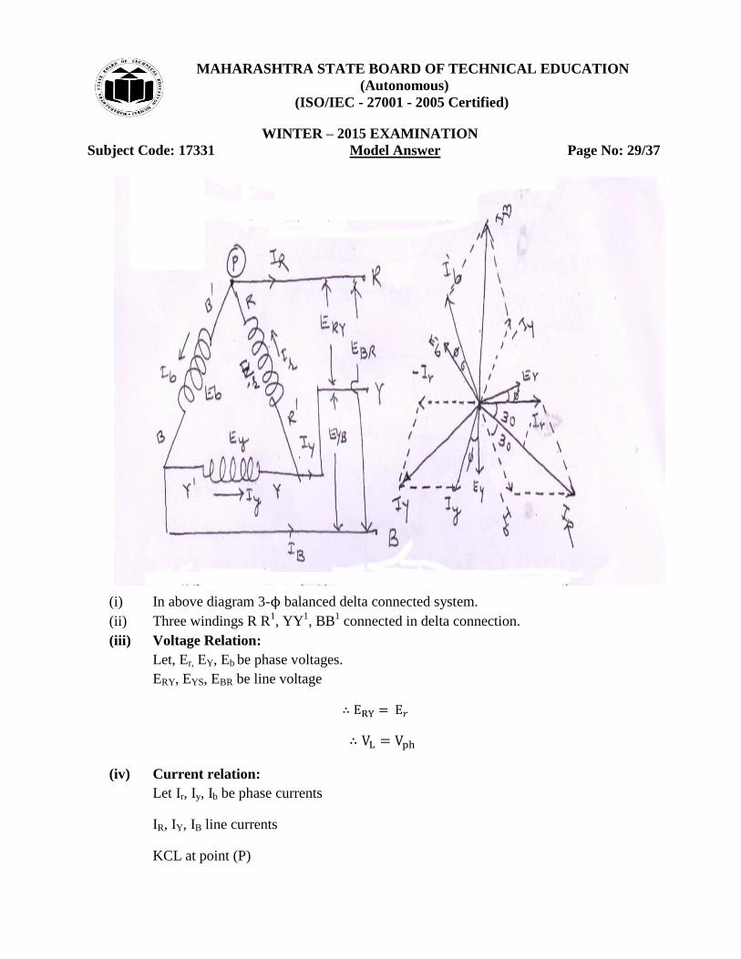
(i) In above diagram 3-ϕ balanced delta connected system.
(ii) Three windings R R1, YY
1, BB
1 connected in delta connection.
(iii) Voltage Relation:
Let, Er, EY, Eb be phase voltages.
ERY, EYS, EBR be line voltage
(iv) Current relation:
Let Ir, Iy, Ib be phase currents
IR, IY, IB line currents
KCL at point (P)
MAHARASHTRA STATE BOARD OF TECHNICAL EDUCATION
(Autonomous)
(ISO/IEC - 27001 - 2005 Certified)
WINTER – 2015 EXAMINATION
Subject Code: 17331 Model Answer Page No: 30/37
Ir= IR+Ib
From phasor diagram
√
√
(v) Power relation
ϕ
=
ϕ
√
√
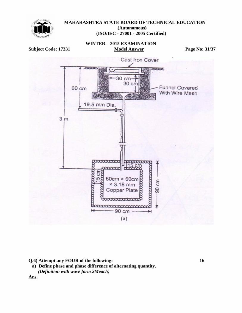
f) Draw neat diagram of plate earthing.
(Correct labelled diagram 4M)
Ans. Diagram of plate earthing:
√
√ 𝑐𝑜𝑠ϕ
MAHARASHTRA STATE BOARD OF TECHNICAL EDUCATION
(Autonomous)
(ISO/IEC - 27001 - 2005 Certified)
WINTER – 2015 EXAMINATION
Subject Code: 17331 Model Answer Page No: 31/37
Q.6) Attempt any FOUR of the following: 16
a) Define phase and phase difference of alternating quantity.
(Definition with wave form 2Meach)
Ans.
MAHARASHTRA STATE BOARD OF TECHNICAL EDUCATION
(Autonomous)
(ISO/IEC - 27001 - 2005 Certified)
WINTER – 2015 EXAMINATION
Subject Code: 17331 Model Answer Page No: 32/37
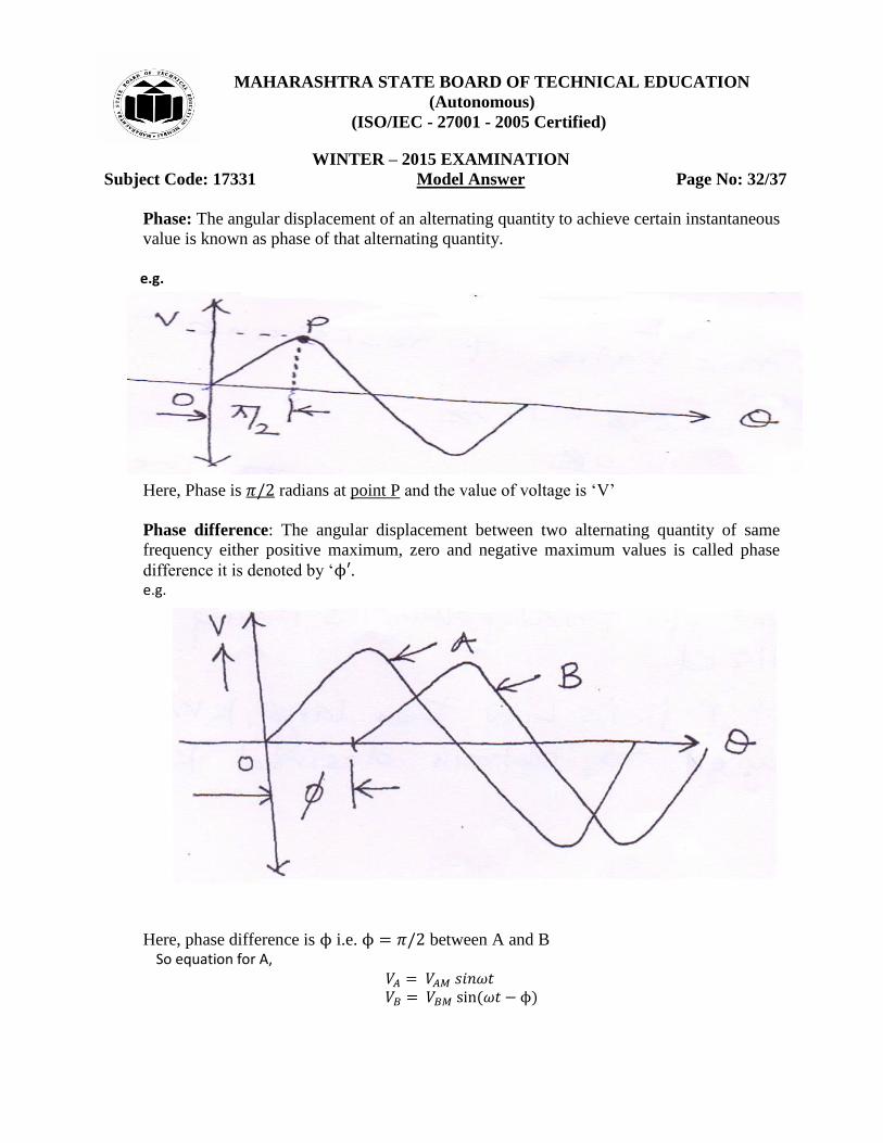
Phase: The angular displacement of an alternating quantity to achieve certain instantaneous
value is known as phase of that alternating quantity.
e.g.
Here, Phase is radians at point P and the value of voltage is „V‟
Phase difference: The angular displacement between two alternating quantity of same
frequency either positive maximum, zero and negative maximum values is called phase
difference it is denoted by „ϕ . e.g.
Here, phase difference is ϕ i.e. ϕ between A and B So equation for A,
ϕ
MAHARASHTRA STATE BOARD OF TECHNICAL EDUCATION
(Autonomous)
(ISO/IEC - 27001 - 2005 Certified)
WINTER – 2015 EXAMINATION
Subject Code: 17331 Model Answer Page No: 33/37
b) State the concept of power factor and write its significance.
(Power factor 2M, significance 2M)
Ans.
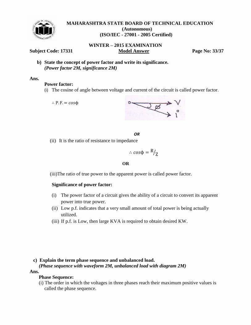
Power factor:
(i) The cosine of angle between voltage and current of the circuit is called power factor.
ϕ
OR
(ii) It is the ratio of resistance to impedance
ϕ ⁄
OR
(iii)The ratio of true power to the apparent power is called power factor.
Significance of power factor:
(i) The power factor of a circuit gives the ability of a circuit to convert its apparent
power into true power.
(ii) Low p.f. indicates that a very small amount of total power is being actually
utilized.
(iii) If p.f. is Low, then large KVA is required to obtain desired KW.
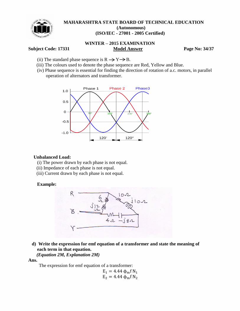
c) Explain the term phase sequence and unbalanced load.
(Phase sequence with waveform 2M, unbalanced load with diagram 2M)
Ans.
Phase Sequence:
(i) The order in which the voltages in three phases reach their maximum positive values is
called the phase sequence.
MAHARASHTRA STATE BOARD OF TECHNICAL EDUCATION
(Autonomous)
(ISO/IEC - 27001 - 2005 Certified)
WINTER – 2015 EXAMINATION
Subject Code: 17331 Model Answer Page No: 34/37
(ii) The standard phase sequence is R Y B.
(iii) The colours used to denote the phase sequence are Red, Yellow and Blue.
(iv) Phase sequence is essential for finding the direction of rotation of a.c. motors, in parallel
operation of alternators and transformer.
Unbalanced Load:
(i) The power drawn by each phase is not equal.
(ii) Impedance of each phase is not equal.
(iii) Current drawn by each phase is not equal.
Example:
d) Write the expression for emf equation of a transformer and state the meaning of
each term in that equation.
(Equation 2M, Explanation 2M)
Ans.
The expression for emf equation of a transformer:
ϕ
ϕ
MAHARASHTRA STATE BOARD OF TECHNICAL EDUCATION
(Autonomous)
(ISO/IEC - 27001 - 2005 Certified)
WINTER – 2015 EXAMINATION
Subject Code: 17331 Model Answer Page No: 35/37
OR
A
A Where,
= Emf induced in primary winding
Emf induced in secondary winding
ϕ = Maximum flux in Weber
f = frequency in Hz
= Number of primary turns
= Number of secondary turns
= Maximum flux density in Wb/
A = Cross-section area of core of transformer
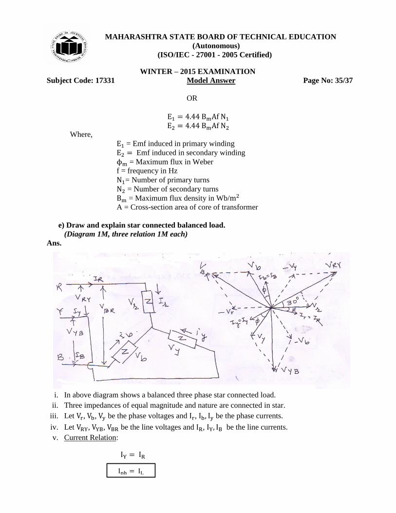
e) Draw and explain star connected balanced load.
(Diagram 1M, three relation 1M each)
Ans.
i. In above diagram shows a balanced three phase star connected load.
ii. Three impedances of equal magnitude and nature are connected in star.
iii. Let , , be the phase voltages and , be the phase currents.
iv. Let , , be the line voltages and , be the line currents.
v. Current Relation:
MAHARASHTRA STATE BOARD OF TECHNICAL EDUCATION
(Autonomous)
(ISO/IEC - 27001 - 2005 Certified)
WINTER – 2015 EXAMINATION
Subject Code: 17331 Model Answer Page No: 36/37
vi. Voltage Relation:
√
√
√
vii. Power Relation:
Total Power
ϕ
=
√ ϕ
√
√
= √ ϕ
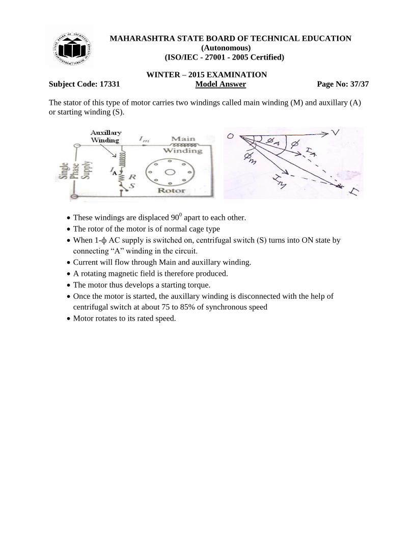
f) Explain resistance split phase single phase I.M. with diagram.
(Diagram: 2M; Explanation: 2M)
Ans.
Figure below shows the circuit diagram of resistance split phase induction motor.
MAHARASHTRA STATE BOARD OF TECHNICAL EDUCATION
(Autonomous)
(ISO/IEC - 27001 - 2005 Certified)
WINTER – 2015 EXAMINATION
Subject Code: 17331 Model Answer Page No: 37/37
The stator of this type of motor carries two windings called main winding (M) and auxillary (A)
or starting winding (S).
These windings are displaced 900 apart to each other.
The rotor of the motor is of normal cage type
When 1-ф AC supply is switched on, centrifugal switch (S) turns into ON state by
connecting “A” winding in the circuit.
Current will flow through Main and auxillary winding.
A rotating magnetic field is therefore produced.
The motor thus develops a starting torque.
Once the motor is started, the auxillary winding is disconnected with the help of
centrifugal switch at about 75 to 85% of synchronous speed
Motor rotates to its rated speed.